Article

Displacements of the Levitation Systems in the Vehicle Hyperloop

1
Faculty of Transport, Electrical Engineering and Computer Science, University of Technology and Humanities, 26-600 Radom, Poland
2
Department of Avionics and Control Systems, Military University of Aviation, 08-521 Dęblin, Poland
*
Author to whom correspondence should be addressed.
Energies 2020, 13(24), 6595; https://doi.org/10.3390/en13246595
Submission received: 22 November 2020 / Revised: 10 December 2020 / Accepted: 11 December 2020 / Published: 14 December 2020
(This article belongs to the Special Issue Hyperloop and Associated Technologies)

Abstract

:
The paper will present a mathematical model for the guideway as a continuous system, followed by a moving force coming from the capsule and the capsule as a discrete system. The theoretical problem selected for analysis comes from a group of technical problems, which solve the dynamics of systems subjected to moving loads. Dynamic reactions in the system are described by a system of coupled partial and ordinary differential equations. Their solution was obtained using approximate numerical methods. The article concerns the analysis of Hyperloop vehicle guideway displacement in the occurrence of magnetic levitation phenomenon, which appears when starting, driving and braking the vehicle. The analysis was carried out using a numerical, three-dimensional model of the guideway. The results of the analysis are illustrated with calculation examples. The displacement of the guideway and magnet elements was determined by simulations. The simulations were conducted using MBS software. The presented results refer to the movements of the capsule of Hyperloop vehicles.

1. Introduction

Hyperloop is the concept of a new (fifth) mode of transport, also called a vacuum train. In this concept, the vehicle, being a hermetically sealed capsule with a load or passengers being carried, moves in a reduced pressure pipe. Assumptions adopted by the creators of this transport speak of lower than high-speed rail infrastructure costs and energy savings due to reduced resistance to movement. Lower resistance to movement is caused by lower air resistance due to the reduced pressure inside the tube being the track and the use of magnetic cushions or other solutions of the chassis systems [1,2,3,4,5,6,7].
Attention is paid to the ecological qualities of this type of transport, because linear electric motors would be used for propulsion, which could be powered by electricity from, inter alia, photovoltaic batteries produced for this type of transport and placed above the tubes used to transport the capsules. The characteristic features of the Hyperloop system are that the vehicle suspension is above the guideway without using the wheels and, therefore, also without cooperation with the rails and through the drive with an induction linear motor. The mechanical system describing the dynamics of the impact of a vehicle operating on the basis of magnetic levitation is a complex spatial system. Tests are usually limited to a vertical plane. Transverse dynamics tests of the system are more important than tests in the vertical plane and complement the dynamics of systems in the horizontal plane.
Detailed analysis of the literature in the field of modeling the dynamics of rail vehicles, due to the popularity of the subject and the variety of issues considered, is not possible to present on several pages. Hence, it was limited to discussing modeling methods used by other authors. In works [8] and [9], rectangular linear coordinate systems associated with the earth (non-inertial system) and a system whose origin of the rectangular coordinate system lies in the center of gravity of individual system solids and axes coincide with central inertia moments are presented. Angles are rotations around these axes (angular velocity vectors lie on the axes of a rectangular coordinate system associated with rigid bodies). Such coordinate systems are used to build vehicles, i.e., Hyperloop, which are used to simulate the movement of a vehicle moving on a beam with a constant cross-section. In work [8], based on the second order Lagrange equations, motion equations for the vehicle system were derived with linear elastic-damping elements also containing elements of the magnetic levitation system. The author of work [10] presented models describing different variants of force action (single, multiple) on the guideway treated as a beam with a constant cross-section. The equations of motion were derived for Hyperloop solids using the second order Lagrange equations.
These methods enable the automatic generation of motion equations and constraints, leading to a system of differential equations for which a number of methods of solving them were developed, initiated by work [11]. In work [12], a description of the model containing a flexible body, along with an analysis of the impact of this structure on the results of calculations can be found. A detailed description of the construction of models is presented in the cycle of works [13,14,15]. They contain different models of magnetic systems and suspension systems. In work [16], a vehicle model was presented containing several differential equations. These works show the possibilities offered by the use of Lagrange formalism and coordinates in a non-inertial system.
Recently, there has been a growing interest in research into new methods of integrating vehicle traffic equations. For example, in work [17], the Runge–Kutta–Rosenbrock method was used to solve the equations of motion of the system with elastic-damping elements. The authors of the article [18] presented some modification of the Runge–Kutta method, enabling effective integration of rigid equations.
The analysis of the interaction between the Hyperloop vehicle and the guideway should be considered in two aspects of the analysis of dynamic systems: the vehicle (capsule) with suspension and the connection of the capsule with the guideway. The elasticity of the guideway should also be taken into account. In a situation where the Hyperloop vehicle capsule moves along the guideway, it is affected by external forces caused by the capsule as well as forces resulting from the dynamics of the suspension system, which causes the appearance of linear and rotational accelerations of the vehicle body. The suspension system reacts to vehicle movement and guideway dynamics as well as irregularities in the guideway surface. In most mechanical models, the guideway is shown as a beam with a constant cross-section in the shape of a T. Moving forces appearing on the suspensions and on the guideway cause forces to arise on the guideway support components. Movements on the guideway support elements are related to the foundation dynamics’ characteristics as well as the forces and moments of the guideway reaction to the support elements [19,20]. This highly coupled process is extremely complicated for mathematical description, which translates into the definition of appropriate assumptions simplifying the mathematical description [21].
The perpendicular deflection of the guideway can be calculated using the modal analysis method. The basis of this method is adopting the guideway model as the Bernoulli–Euler equation. The movement of the guideway y(x, t), which is variable in space and time, is represented as the sum of its natural modes (vibration cycles). This method is suitable for solving the problem of one-dimensional oscillations. Based on the assumption that vertical movement dominates and that the vertical, lateral and torsional movements of the guideway are independent, in this article, attention will be focused mainly on the deflection of the vertical guideway when analyzing the Hyperloop/guideway interaction [22,23]. The methods of identification of guide bar wear are discussed in the publication [24].
In the process of determining the natural vibrations and the displacement of the guideway, it is important to be able to accurately predict the reaction of the guideway to the action of the mechanical system, which is a capsule with elastic-damping suspension. In addition, the guideway must ensure acceptable riding efficiency (low deflections) and should be characterized by very good material strength. To assess the scope of design of running rails in the Hyperloop system for different operating conditions, it is necessary to develop a simulation technique for the capsule–guideway interaction system. The dynamic interaction process can be modeled with different levels of accuracy and edge conditions characterizing the guideway model as a beam with a constant cross-section with a moving mass with elastic-damping elements. The research described in the article includes dynamic models for a vehicle with magnetic levitation moving at a constant speed on a straight guideway. The mechanical model under consideration can be divided into two types. The first vehicle is simulated as moving forces on guideways, and those that model the vehicle as a system with many degrees of freedom, describing vehicle dynamics and suspensions in the form of masses of solids, springs and linear shock absorbers. The complex capsule–guideway interaction model, which consists of a guideway, vehicle body, bogies, electromagnetic suspension system and guideway surface irregularities, can be simulated using numerical integration algorithms that calculate system dynamics in real time using information contained in a mechanical model. Therefore, the models built cannot be too complicated, as the calculation time and the number of necessary data characterizing the modeled real object increases as the model complexity increases. On the other hand, too simple models may not reflect all the properties of real objects relevant to applications in real conditions. It is difficult for them to achieve compliance with the results of experimental studies characterizing the behavior of real objects. The models used for computer simulation contain a number of simplifications that have a decisive impact on the quality of the results obtained. The model presented in the work is composed of a series of rigid bodies connected with elastic-damping elements. The second order of Lagrange equation method was used to derive the equations of motion. Movement equations are generated by their own computer program, based on an algorithm that takes into account the structure and degree of complexity of the model.

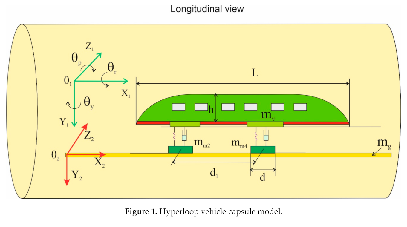
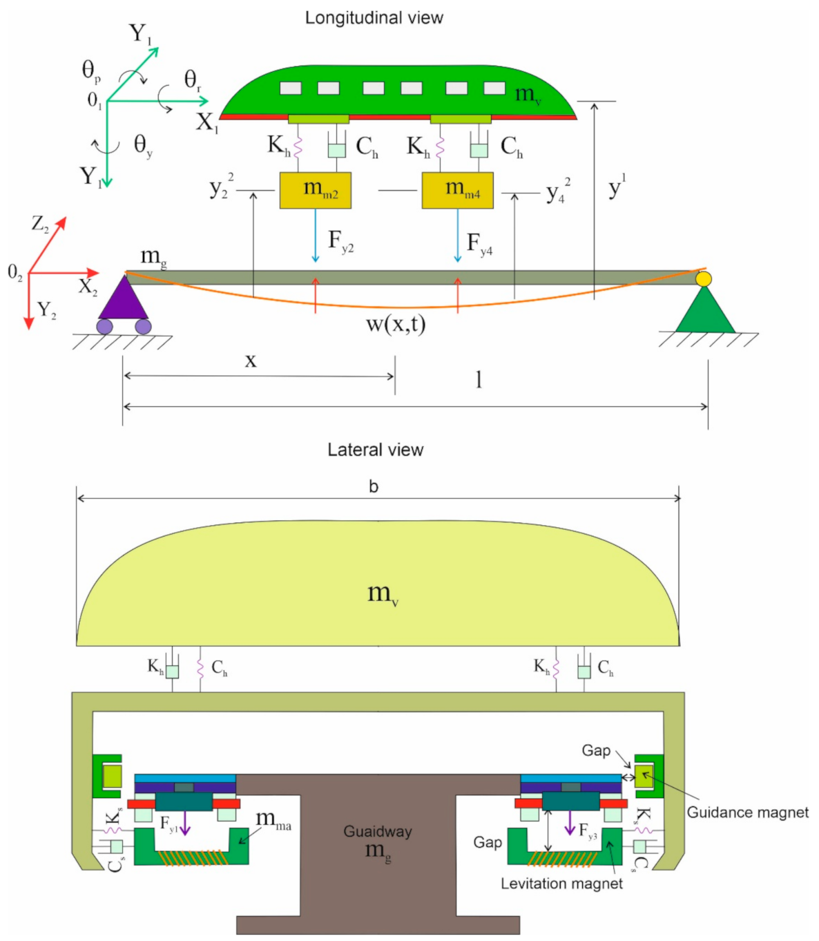
2. Construction of the Nominal Model

Capsule models and quantities of geometric parameters, susceptibility and linear and angular coordinate systems to describe the phenomena of the guideway and capsule will be presented.
The model of the tested Hyperloop type object is shown in Figure 1. For the analyzed mechanical model, the tube length specified by L was defined. The Hyperloop-type vehicle will be treated in mathematical considerations as a discrete model of a solid of a mass of m1 (capsule) and two magnetic sets. Individual elements included in the discrete model of the vehicle of Hyperloop type were connected by linear flexible elements.
Electromagnetic forces responsible for the attraction of the capsule to the guideway cause the phenomenon of “rocking” of the object between the magnetic elements and the guideway, which are controlled by electrical circuits. The processes occurring during the movement of the capsule over the tube result from the phenomenon of magnetic levitation. Flexible elements connecting mass elements in Hyperloop constitute the first and second stage of suspension. In mathematical equations, the symbol 1 denotes the value occurring in the suspension of the first degree, and the value 2 refers to the suspension of the second degree. The geometric quantities characterizing the vehicle capsule were defined as L × b × h, where L—the length of the capsule, b—width and h—height. The mass of the capsule is denoted by mv and the mass of the magnetic element by mm. It was assumed that the spring element and damper are linear subunits for which the elasticity coefficients and damping coefficients were marked by Kh and Ch, respectively. According to Figure 1 and Figure 2, two coordinate systems were adopted: one O1X1, O1Z1, O1Y1 rigidly connected to the tube, and the other O2X2, O2Z2, O2Y2, whose origin of the coordinate system lies in the center of the mass of the capsule and magnets and the axes of the coordinate system on the axes of mass symmetry. This coordinate system also adopts angular coordinates whose velocity vectors lie on the axes of the O1X1Z1Y1 system, and the angles are rotation angles around these axes of the coordinate systems, which we call, respectively: pitch, yaw and roll. These angles are marked θ r , θ p , θ y , respectively. Following the work [8], a matrix of zero–one directional cosines (ones on a diagonal) was adopted.
The suspension should also include a magnetic circuit, which consists of magnetic elements, ferromagnetic guideways, and the air area between the magnets and the guideway. The resistance and magnetic resistances occurring in the magnetic circuit are represented, respectively, by Ra and Rq (a = q = 1, 2, 3 and 4). In the next stage of mathematical considerations, the iron guideway displacements defined by w(t, x) for the x coordinate occurring at time t were defined. An analogous procedure was adopted for determining the displacement for the magnetic element acting on the guideway, described as w1(t, x). For the magnetic element displacement, all four positions of the magnetic elements indicated by ya and za (a = 1, 2, 3 and 4) should be taken into account. The displacements of the capsule in the y and z axes were defined for the first and second stages of the Hyperloop suspension in the O1X1Y1Z1 coordinate system shown in Figure 2. According to the linear properties of the spring and damper and the equation describing the value of magnetic force, the following relationships were obtained:
Force of elasticity for the capsule moving in the tube:
K h y 1 y a 2 , K s y 1 y a 2 , a = 1 , 2 , 3 , 4
Viscous damping forces for the capsule:
C h d y 1 d t d y a 2 d t , C s d z 1 d t d z a 2 d t , a = 1 , 2 , 3 , 4
Magnetic forces in the magnetic levitation system:
F y a = φ a 1 t μ 0 A a , F z a = φ a 1 t π a 2 e a 2 μ 0 A a 1 , a = 1 , 2 , 3 , 4
where magnetic components of vertical forces occurring in vertical and transverse motion are determined by Fya and Fza, this is magnetic permeability in a vacuum, A a   =   c 2 a   ×   ( d 2 a e 2 a ) , a   =   1 , 2 , 3 , 4 is the active area between the capsule and the guideway. The magnetic field generated in this area was defined as ϕ a and is associated with magnetic resistance R a . The mathematical relationship describing the phenomenon of magnetic field shaping is as follows:
ϕ a = N I a t R a ,   a = 1 , 2 , 3 , 4
in which N is the number of coils used in the electric circuit, Ia represents the control current present in the magnetic levitation system, and
R a = R 0 + r s a t ,   a = 1 , 2 , 3 , 4
where r = 2/ μ 0 A 0 , s a ( t ) = δ a ( t ) δ 0 a disturbance occurring in the y axis, in turn, the parameter R 0 means the magnetic resistance between the magnetic set and the guideway in a state of static equilibrium, and δ 0 means the gap between the magnetic set and the guideway. The quantity δ a determines the air gap and is described by the relationship:
δ a t = y a 2 t w a t , a = 1 , 2 , 3 , 4

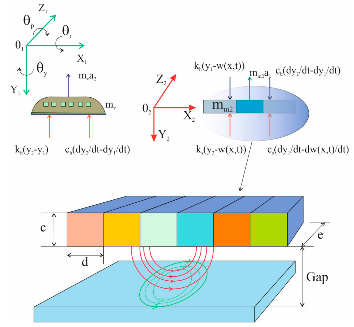
3. Hyperloop Equations of Motion

Using the d’Alembert principle, the motion equations describing the dynamics of a Hyperloop vehicle can be written:
m v d 2 y a 2 d t 2 C h d y 1 d t d y a 2 d t K h y 1 y a 2 = m g F y a , a = 1 , 2 , 3 , 4 m v d 2 z a 2 d t 2 C h d z 1 d t d z a 2 d t y z 1 z a 2 = F z a , a = 1 , 2 , 3 , 4
and
J p d 2 θ p d t 2 + C p d 2 θ p d t 2 K p θ p = J r J y θ r d t · θ y d t L p J y d 2 θ y d t 2 + C y d 2 θ y d t 2 K y θ y = J p J r θ p d t · θ r d t L y J r d 2 θ r d t 2 + C r d 2 θ r d t 2 K r θ r = J y J p θ y d t · θ p d t L r
where the parameters θ p , θ y , θ r are angles describing, respectively, the rotation in the direction of pitch, yaw and roll of the capsule in the O1X1Z1Y1 coordinate system associated with the capsule. The values J p , J y , J r mean the moment of inertia along these axes.
The first component of Equation (8) is the product of the angular acceleration vector and the moment of inertia vector appearing on the second suspension stage around the O1X1Z1Y1 axis, which can be written, respectively:
J p = 1 12 m v L 2 + b 2 J y = 1 12 m v L 2 + b 2 J r = 1 12 m v h 2 + b 2
and the parameters L P , L y , L r are inertia forces occurring around three revolutions around the O1X1Z1Y1 axis. The mathematical notation is as follows:
L p = d 1 2 C h d y 4 , 2 d t + d y 3 , 2 d t d y 2 , 2 d t d y 1 , 2 d t K h y a , 2 + y a , 2 y a , 2 y a , 2 cos θ p     a = 1 , 2 , 3 , 4 L y = d 1 2 C s d y a , 2 d t + d y a , 2 d t d y a , 2 d t d y a , 2 d t K s y a , 2 + y a , 2 y a , 2 y a , 2 cos θ y     a = 1 , 2 , 3 , 4 L r = d 2 2 C h d y a , 2 d t + d y a , 2 d t d y a , 2 d t d y a , 2 d t K h y a , 2 + y a , 2 y a , 2 y a , 2 cos θ r     a = 1 , 2 , 3 , 4
Displacements occurring on the guideway taken as the Euler–Bernoulli beam can be written using the equation:
E J 4 w x 4 + C h w t + ρ 2 w t 2 = η 1 t , x a = 1 2 F y a L a 2 + η 2 t , x a = 1 4 F y a L a 1
in which
η 1 t , x = 1   f o r   v t L a 1 2 x v t + L a 1 2 0 η 2 t , x = 1   f o r   v t d 1 L a 2 2 x v t d 1 + L a 2 2 0
where L a 1 = L a 2 .

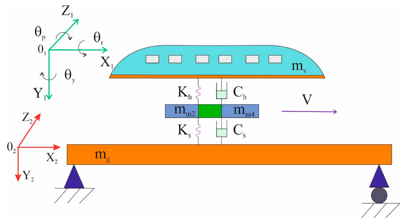
4. Subsection Discrete Mathematical Model of the Guideway Load by Hyperloop

In the mechanical model describing the behavior of electromechanical forces acting on the guideway, it was developed based on two rigid masses representing the bogie and the mass of the Hyperloop capsule (Figure 3). The model takes into account two degrees of suspension assuming that the susceptibilities are linear. For mathematical equations describing the dynamics of Hyperloop, three coordinates were taken into account for the vertical movement of the capsule, the vertical movement of the magnet and the vertical displacement of the guideway (Figure 4). For the capsule body, the equation of motion is given below:
m v d 2 y 2 d t 2 + C h d y 2 d t d y 1 d t + K h y 2 y 1 = 0
where: mv carriage body mass, y2 vertical displacement of the carriage body, y1 vertical displacement of the levitation set, Ch damping of the second stage suspension system, Kh stiffness of the second stage suspension.
The vertical motion equation for levitation suspension is as follows:
m v d 2 y 1 d t 2 C h d y 2 d t d y 1 d t K h y 2 y 1 + C s d y 1 d t d w x , t d t + K s y 1 w x , t = 0
where m1 mass of the levitation set, w(x, t) vertical displacement of the guideway in place x and time t, Cs damping value of the first suspension stage, Ks stiffness of the first suspension stage.
The equation of the guideway motion in the natural vibration range (14) can be written as [10]:
d 2 A k t d t 2 + 2 ζ k ω k d A k t d t + ω k 2 A k t = m m + m v g + c s d y 1 d t d w x , t d t + k s y 1 w x , t 2 m v L sin k π v t L = 0
Displacements occurring on the guideway can be determined from the expression:
w x , t = k = 1 A k t ϕ k x = k = 1 A k t 2 sin k π v t L
Ak(t)—displacements along the guideway.

5. Hyperloop Vehicle Modelling in MBS Software

In Hyperloop studies [1,5,18], no studies dealing with the problem of capsule movement and the cooperation of magnetic elements with the guideway placed in the tube are carried out. Vertical and transverse displacements occur in the contact of the guideway placed in the tube with the elements placed in the capsule (with the capsule moving). The lateral displacements may lead to the cooperation of the magnetic elements of the capsule with the tube guideway. Prolonged contact of the two elements can damage (mainly) the magnetic elements of the capsule. Therefore, the study of the transverse displacements of the capsule is an important element that will be conducted.
The numerical analysis of the determined displacement trajectories in the capsule of the Hyperloop vehicle required the construction of a nominal model. The nominal model consisted of a rigid body-capsule, levitation suspension, beam as a guide, driving elements and a tube. The nominal model was the basis for creating a mathematical model and then a calculation model. The calculation model was designed in MBS class software environment. It consisted of 202 rigid solids. Each block was assigned material, mass and moments of inertia. Moreover, the following were defined in the calculation model: geometric bonds between individual solids, models of contact between selected solids and vectors of forces and moments of inertia necessary for the simulation. The simulations and numerical analyses were aimed at determining the displacements of generalized coordinates of the capsule at different speeds and accelerations occurring in the analyzed system, both in the capsule and the levitation system.
In the dynamic testing procedure of the vehicle was to build a simplified, 3D CAD model of the structure. The model of an exemplary structure was made in Solidworks (Figure 5). In the model, the mass distributions on the capsule’s base were recorded discretely. Individual components were presented in the form of rigid solids of a given mass and placed in places of their actual position. Thanks to this, it was possible to make a complete structure assembly, which will be used to calculate mass moments of inertia and find the center of gravity of the capsule body (Figure 5). In the same way, information about the design of the guideway was obtained. Thanks to the discretization of the CAD model it is possible to quickly modify the distribution of masses of components for the capsule and the levitation system. Moments of inertia in matrix form have been saved for two types of construction and prepared for implementation into MBS. The exemplary capsule model consisted of three subsystems: the body and the front and rear levitation set. The main parts of the model were created in three steps. The first step was to define the location of the points determining the location of the parts. Then, the actual part was created on the basis of the defined points with defined mass moments of inertia. The last step was to add the geometry of the capsule part. For each subsystem, new templates were designed, which were based on the vehicle’s technical documentation, technical and operational characteristics of the vehicle and information obtained during the CAD modelling stage. The results of the simulation are presented as generalized trajectories in the time domain. This article presents sample results for each of the listed generalized coordinates. Additionally, the amplitude–frequency spectra of the capsule signals from all measuring points recorded on the driving distance at 1000 and 2000 km/h, as shown in Figures 18–21 and 26–29. Due to the safety of using Hyperloop, the study of displacements and vibrations resulting from the cooperation of electromagnetic elements with the guideway should be performed in order to be able to correctly select the quantities characterizing the magnetic levitation process. One of the basic simulations analyses to be carried out before the implementation of the Hyperloop vehicle is the determination of the lateral displacements of electromagnetic elements caused by the movement of the capsule.
In the simulation process, a guideway model was adopted, shown in Figure 5.
The Hyperloop capsule is a unit to which elements generating the phenomenon of magnetic levitation, responsible for propelling the capsule, are attached. It consists of two rigid bodies on which modules with electromagnets and linear induction motors are mounted, and two counter-rotating and decoupling mechanisms. The authors of the article formulated a dynamic mathematical model described by means of second-degree differential equations taking into account concentrated magnetic forces acting on the guideway. The magnetic force generated on each electromagnet acts vertically on the tube guideway and is concentrated in the center of the magnets mounted on the capsule bogie of the Hyperloop vehicle.
When formulating the dynamic equations of the Hyperloop vehicle model, the following assumptions are made:
  • The distribution of the magnetic field throughout the Hyperloop capsule bogie is uniform along the entire face of the electromagnets.
  • The penetration of the magnetic field of the electromagnet resulting from the phenomenon of magnetic levitation and its edge distribution is ignored.
  • The set of electromagnets is a rigid body so that the levitation slots in its subsections can be defined by the slots at the ends of the electromagnet’s module.
  • Inequalities in the guideway are ignored (neglected).
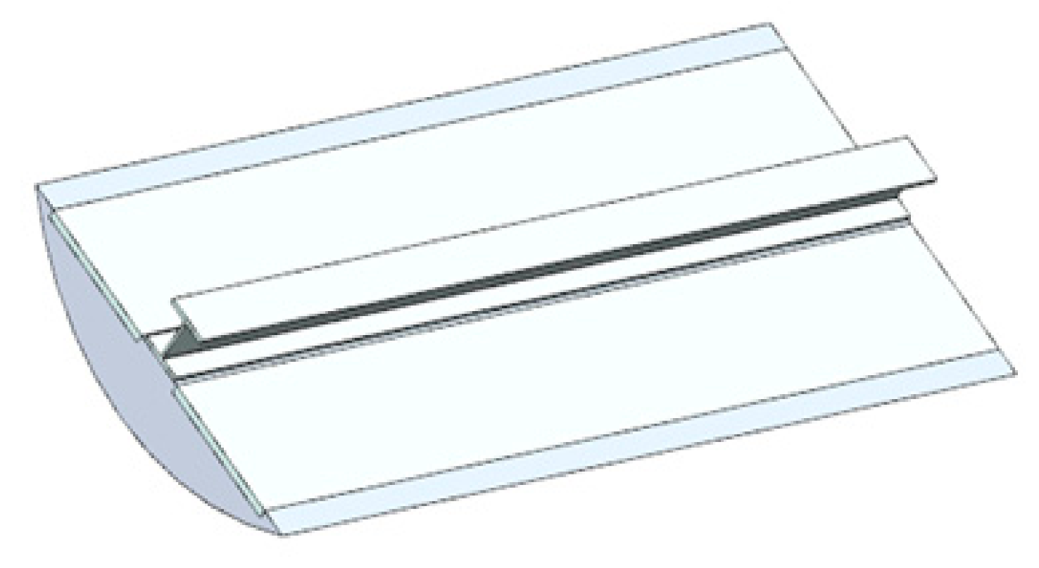
  • The tube guideway will be considered as a rigid beam, so any deformations on the guideway can be ignored.
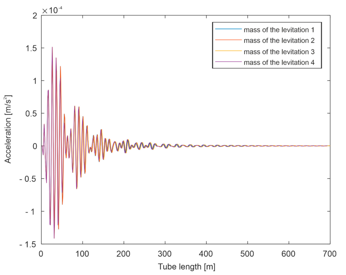
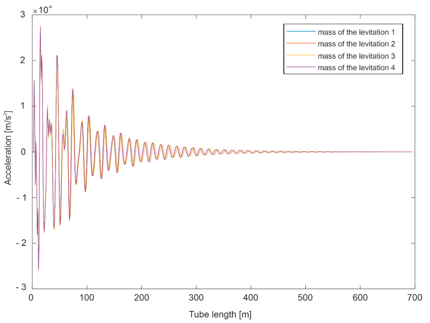
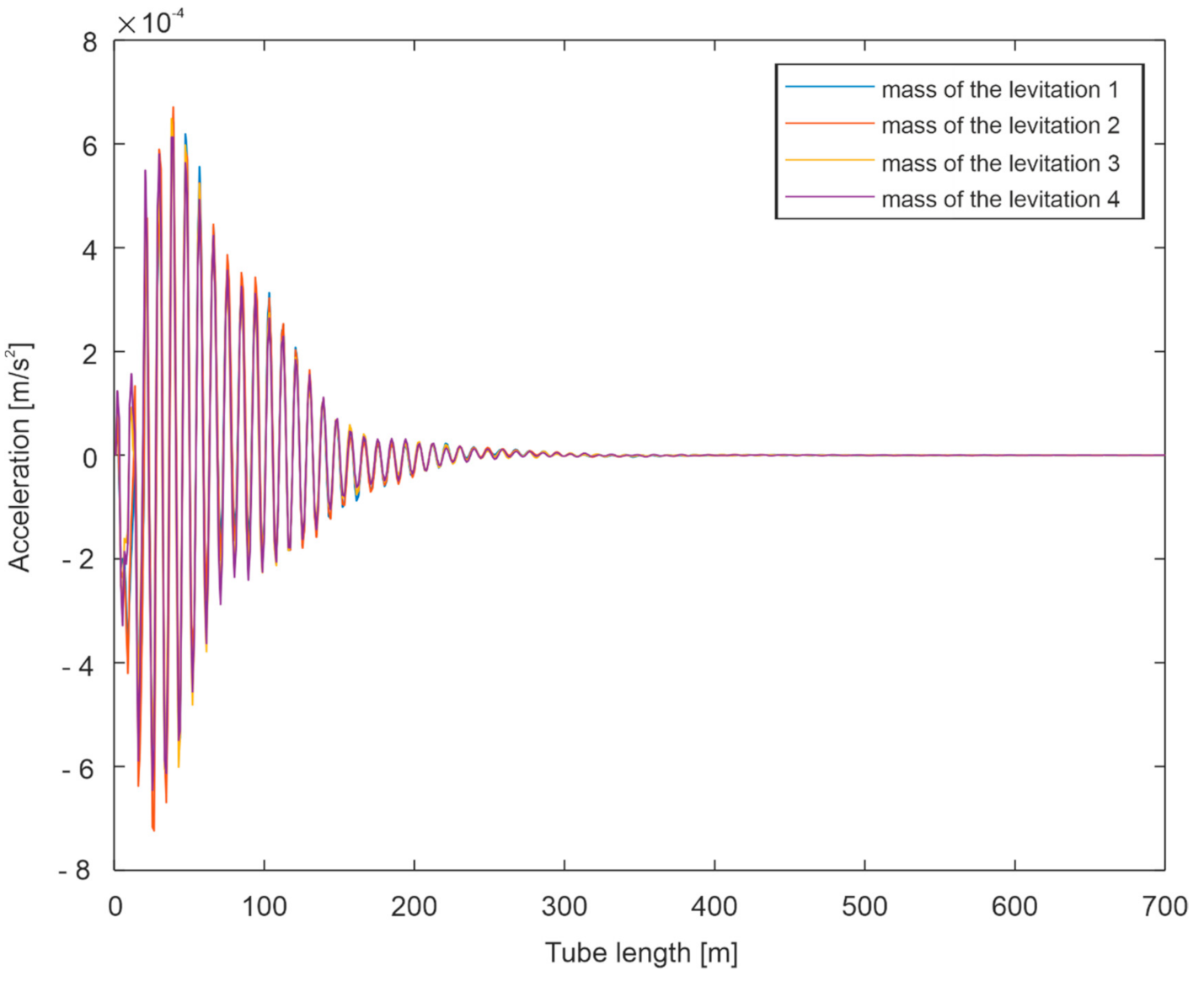
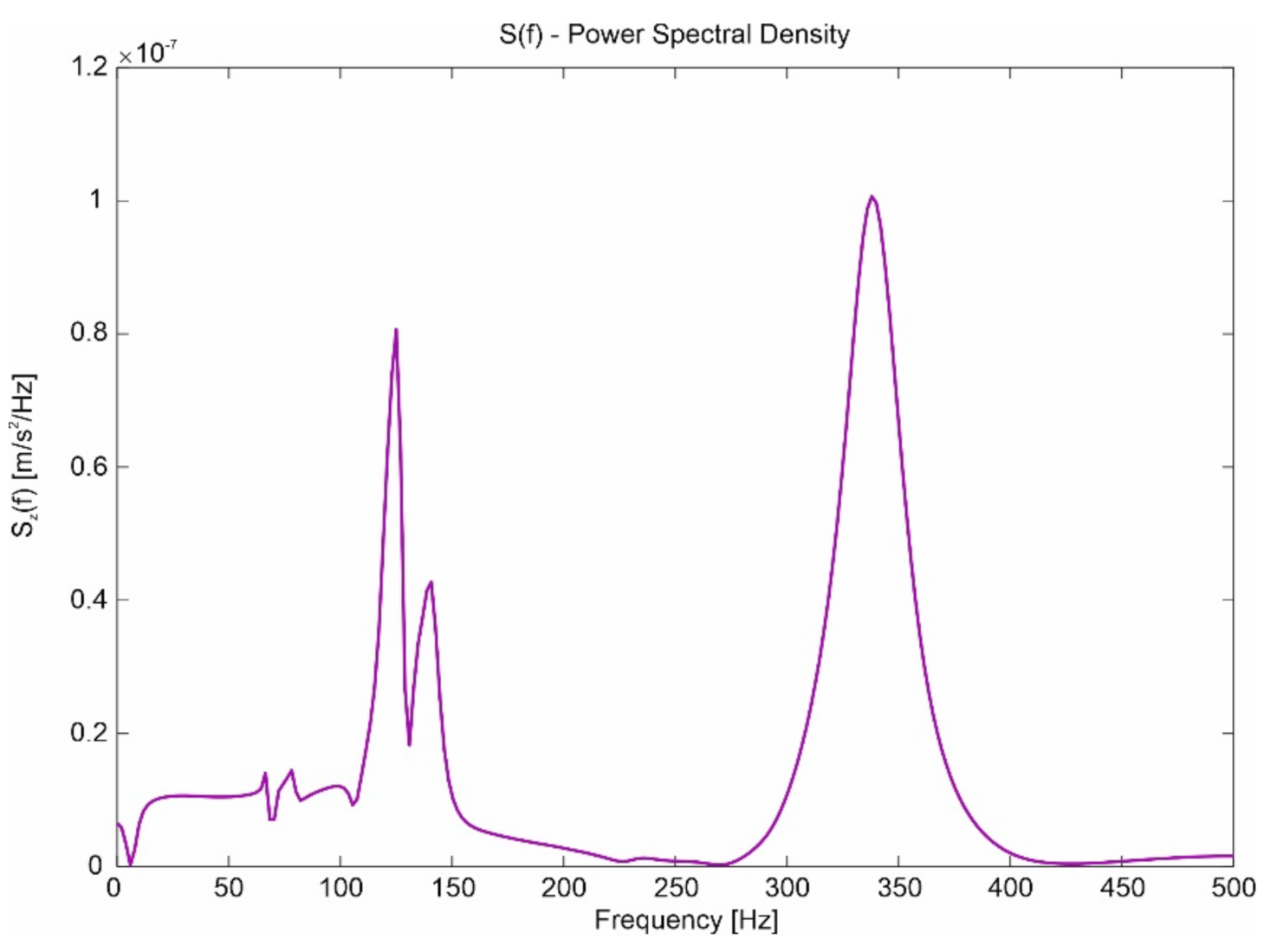
Simulation Tests

Computer simulations will be carried out to determine the dynamic behavior of the mechanical system of the levitation unit and the tube guideway. The influence of the Hyperloop vehicle speed on the arising vertical and lateral clearances is investigated. Vehicle speeds of 1000 and 2000 km/h are used for the analyses. The guideway parameters adopted in the simulations are presented in Table 1, while the capsule parameters are presented in Table 2.
Due to the safety of using Hyperloop, the study of displacements and vibrations resulting from the cooperation of electromagnetic elements with the guideway should be performed in order to be able to correctly select the quantities characterizing the magnetic levitation process. One of the basic simulations analyses to be carried out before the implementation of the Hyperloop vehicle is the determination of the lateral displacements of electromagnetic elements caused by the movement of the capsule.
In computer simulations, special attention was paid to the phenomenon of the movement of the gap between the magnets mounted on the Hyperloop capsule bogie. In the conducted research, the changes in the gap at different vehicle speeds were examined, taking into account the displacement of the magnets, the article investigates whether the discussed phenomenon affects the travel of the capsule along the guideway and whether the levitation magnets will not touch the guideway. The results were carried out for two different speeds of 1000 and 2000 km/h.
The simulation results in Figure 6, Figure 7, Figure 8, Figure 9, Figure 10, Figure 11, Figure 12 and Figure 13 relate to four cases. Two cases related to two types of magnets were considered: guidance magnet and levitation magnet. For each of these magnets, simulations for 1000 and 2000 km/h of capsule motion were performed. The lateral displacement and the rate of changes in these displacements were determined. The presented diagrams show that none of these magnets exceed the permissible clearances between the magnets and the guide. The guidance magnet clearances at 1000 and 2000 km/h are of the same nature. The right and left sides work against phase. For the nominal start-up for this type of magnet, the displacement values are within the permissible clearance—2 mm.
In the next computer simulations, measurements of the lateral and vertical displacements of the capsule were carried out. In the case of vertical and lateral displacements, the sensors in the Hyperloop vehicle model were placed between the capsule and the levitation set. The whole process, as it was in the case of determining the displacement of the levitation set, was carried out for two different speeds of 1000 and 2000 km/h. Detailed analyses of the recorded displacement waveform were performed, and the values of extreme spectral amplitudes were determined. These values will be compared for the displacement simulations of levitation magnets discussed in the next section.
An exemplary list of vertical displacement waveforms on the capsule in the y direction, determined for the travel speeds of 1000 and 2000 km/h, are shown in Figure 14 and Figure 15, and the transverse directions of the capsule for the z direction are shown in Figure 16 and Figure 17.
The vibration frequencies were determined on the basis of the analysis of forced displacements during the travel of the capsule and the calculations of the spectral density. The spectra were made with MATLAB software using fast Fourier transform (FFT). Spectral analysis (determined values [m/Hz]) will allow us to determine which frequencies will appear in the trajectory of movement of individual generalized coordinates describing the Hyperloop solids. The determination of these frequencies will allow for the determination of dynamic couplings between different frequencies of individual solids of systems, e.g., frequencies of eigenmodes of continuous systems. Mendelstam’s theory is used in the definition of dynamic couplings. Spectral analysis is an essential element for analyzing dynamic phenomena occurring in Hyperloop. Such analyses will be the subject of further analytical studies of dynamic phenomena in Hyperloop. The waveforms of the spectrum are shown, respectively, for the vertical displacements in Figure 18 and Figure 19 and in Figure 20 and Figure 21 for the transverse displacements of the capsule.
Based on the analysis of the determined values, it can be concluded that in the vertical displacements of the capsule there are components with the lowest frequencies equal to f1 ≈ 120 Hz for vibrations in the vertical direction. For lateral displacements at 1000 km/h, the frequencies have two maxima: one around 120 Hz and the other around 350 Hz. At a speed of 2000 km/h, a maximum remains around 120 Hz, while the maximum at 350 Hz is canceled.
Then simulations were made to determine the acceleration of the magnet around the z axis and around the y axis for speeds of 1000 and 2000 km/h.
From the graphs presented (Figure 22, Figure 23, Figure 24 and Figure 25), it can be seen that in none of these movements is a contact of magnets with a guideway (friction). The clearances in the y-axis direction are 8 mm and in the z-axis direction 2 mm.
Then, a spectral analysis of the obtained acceleration quantities in both directions was carried out. In the z-axis direction, the spectrums for speed of 1000 km/h are shown in Figure 26, and for 2000 km/h in Figure 27.
The spectral analysis of the gaps between the guideway and the levitation set mounted on the bogie will also be performed, as well as the spectral analysis of the change in the size of the lateral clearance between the guideway tube and electromagnetic elements. These results can be used to study the relationship between the frequencies appearing on the movement of the Hyperloop capsule and on the guideway, which may cause the appearance of dynamic couplings. It will be possible to determine whether a dynamic coupling can arise between the capsule and the guideway, if it is assumed as a deformable beam (according to Mendelstam’s theory).
As can be seen from the graphs presented, two peaks appear for the speed of 1000 km/h: one within approx. 130 Hz and the other within approx. 350 Hz. This is due to the features of the electromechanical system, which can be seen on the graph of the displacement of the magnet in the z-axis direction. The increase in speed causes the second peak to be eliminated, which seems reasonable as the elimination of certain system features show displacements in the z-axis direction.
For acceleration in the y-axis direction, the spectrum for the speed of 1000 km/h is shown in Figure 28, and for 2000 km/h in Figure 29.
The analysis of the simulation results (Figure 26, Figure 27, Figure 28 and Figure 29) shows that low-frequency components are dominant, as in the case of the rail vehicle, while for increasing the speed of the capsule.
When analyzing the above results, one can observe:
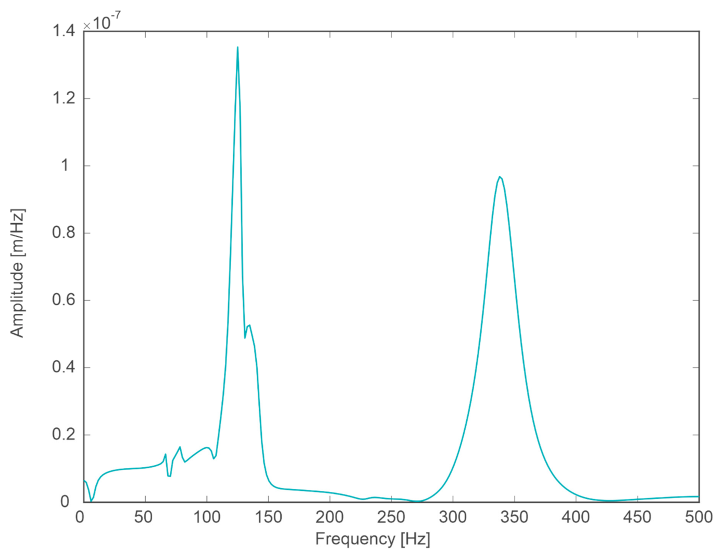
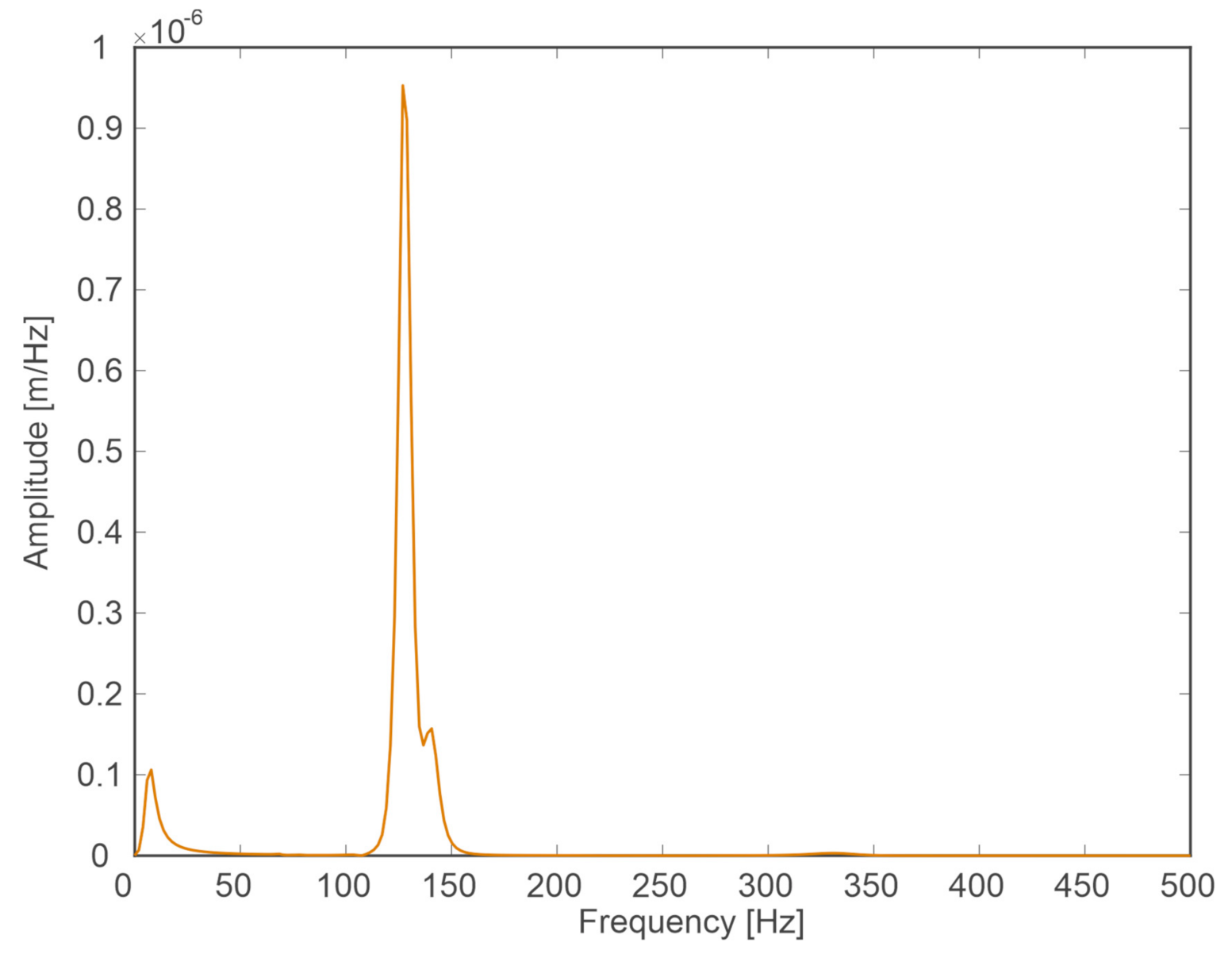
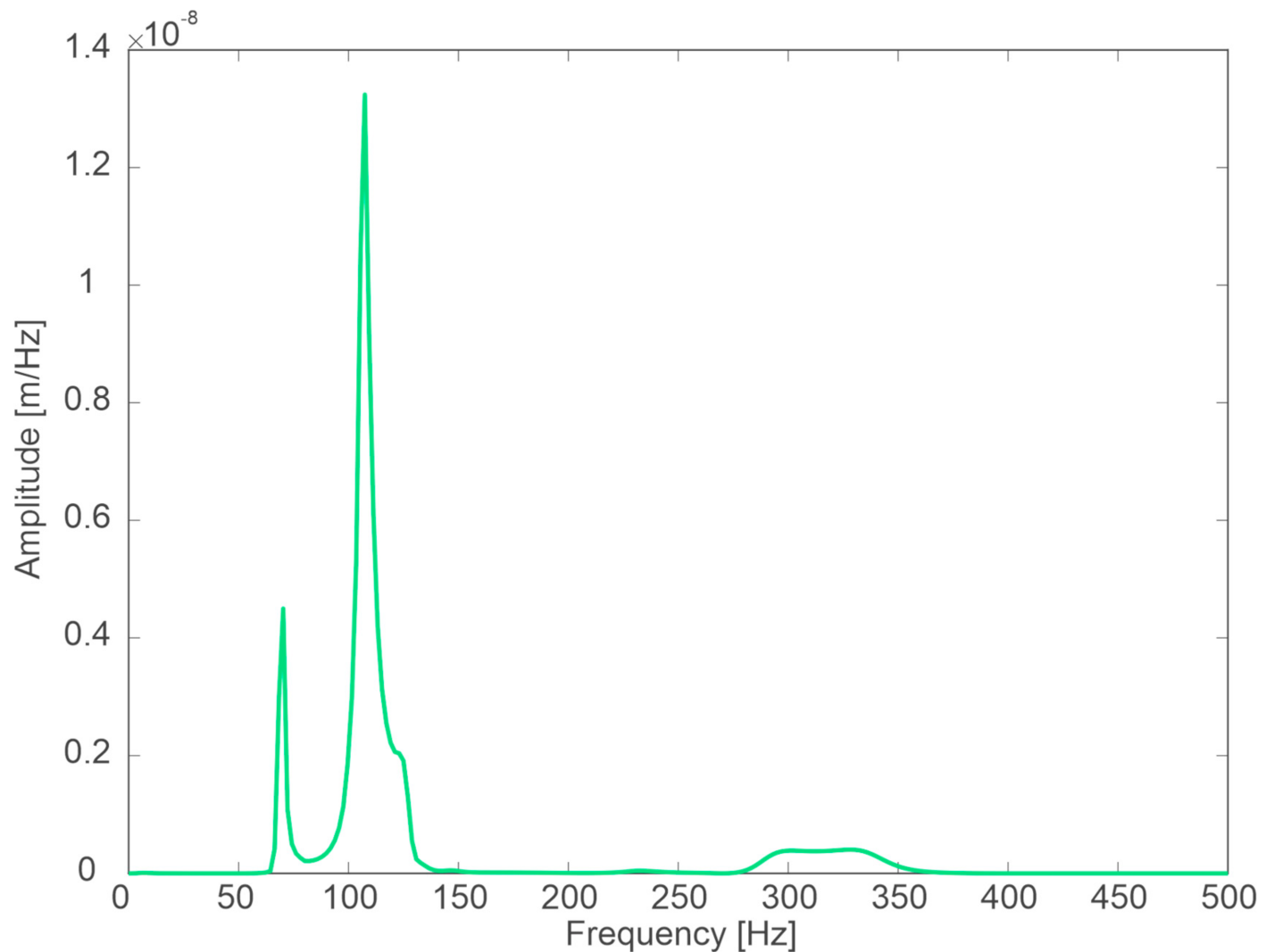
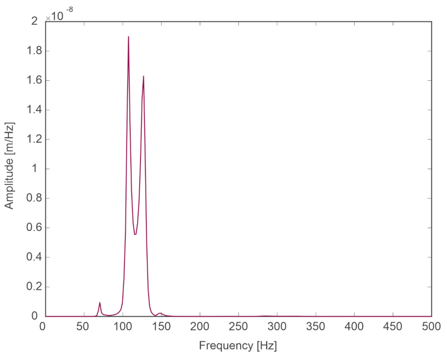
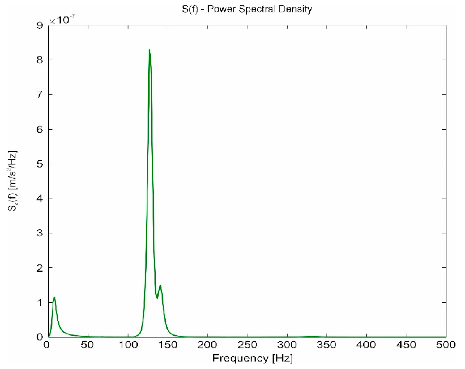
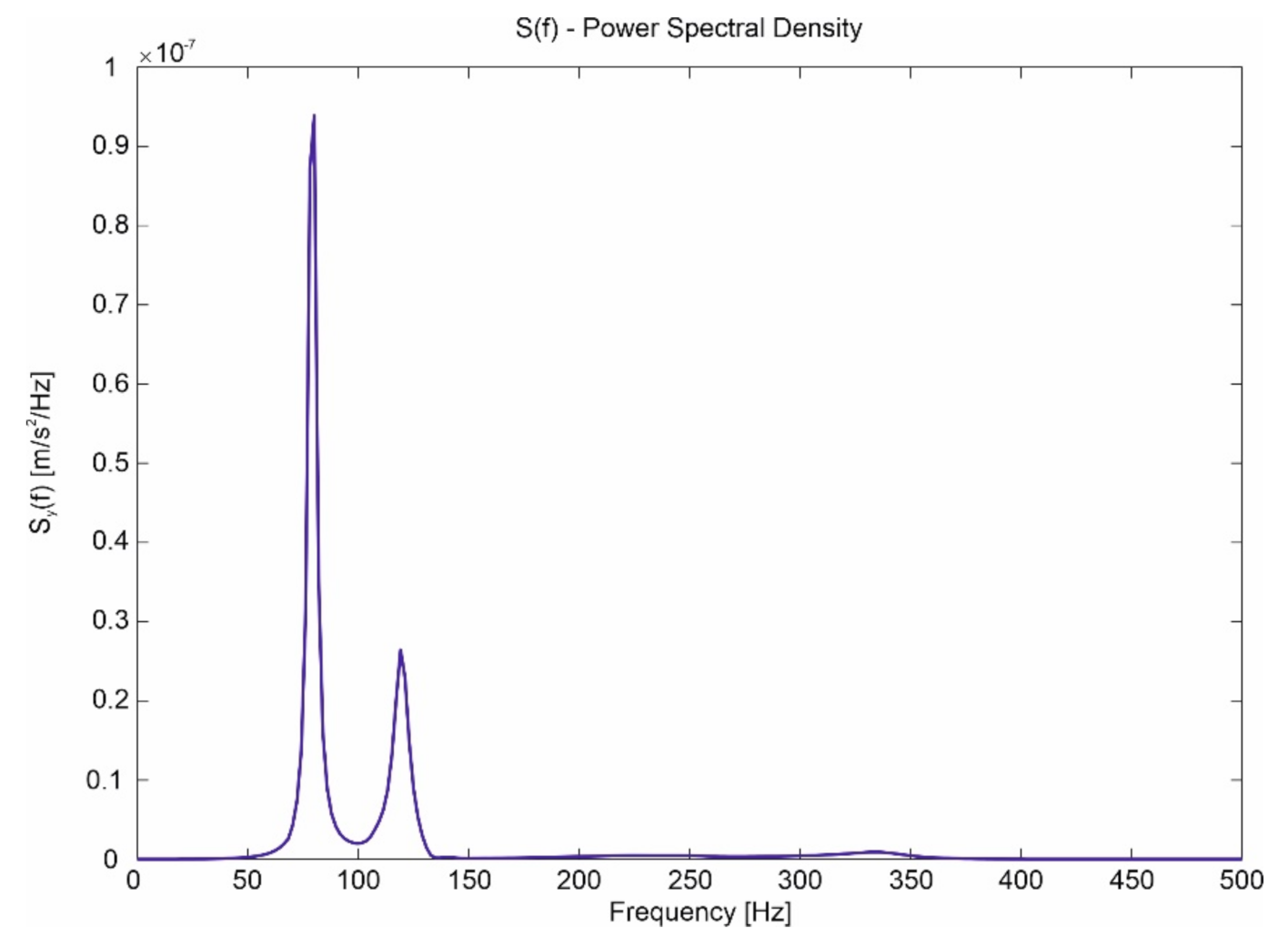
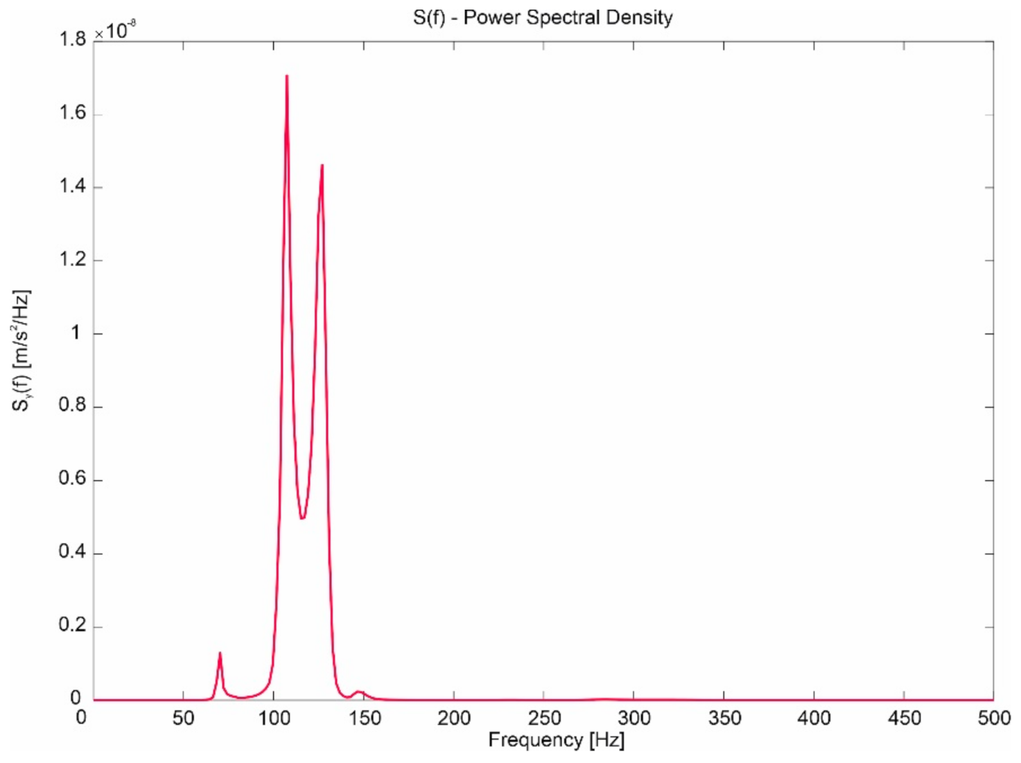
  • Negligible influence of the slit width on the spectrum in the case of a change in capsule velocity and a clearly marked band of frequencies dominating in the signals (approximately 60–150 Hz).
  • Clear influence of the substrate on which the guideway is located on the spectrum in the event of a change in the speed of the capsule.
From the graphs presented, it can be seen that the increase in speed causes the maximum frequency spectrum to be shifted almost twice. This is consistent with the physics of such phenomena.
In Figure 18, Figure 19, Figure 20, Figure 21 and Figure 26, Figure 27, Figure 28, Figure 29, we can see that, when damping occurs, the displacements also disappear as the distance from the source of harmonic extortion increases, creating a fading standing wave. However, in the case of an extortion with a frequency higher than the natural frequency, two peaks are excited that do not disappear. As the frequency increases further, the amplitude of these waves and their length decreases. A case of fading of waves in a perfectly resilient system is also obtained in the case of a periodic system in space. The effect similar to strong attenuation with energy dissipation is caused by a given spatial periodicity in the frequency range, which we call the fade band. It should be noted that, in case of a perfectly elastic periodic structure, the periodic structure is not an obstacle to the propagating waves. Waves do not fade away. A qualitative difference in propagation of the disturbances can occur at any small frequency difference. It is only important that there is a borderline between the two frequencies of the forcing band and the fading band. In the real circuit, the case of the frequency band is unfavorable. In order to counteract unfavorable phenomena occurring in systems with periodic structure, the "mistuning" effect is applied. As it results from the presented spectra, the largest frequency components concern measurement points located on the shaft of the levitation unit. Their frequency is about 60–150 Hz. Other measuring points do not have higher amplitudes.

6. Conclusions

The presented method of modeling the Hyperloop system together with the guideway and magnet elements as a combination of a discrete and continuous model gives the opportunity to assess the behavior of individual masses during movement. The presented equations of motion were implemented for mass-inertial linear values of susceptibilities and levitation forces in a form enabling the introduction of various detailed quantities, which may be different for different constructions. A model with one guideway and four magnet systems was considered. Simulations were carried out for specific systems, which showed that in horizontal and vertical movement there are amounts of displacements that are within the limits of transverse and vertical clearance between the guideway and the magnet elements, they are for the transverse direction of 2 mm, and for the vertical direction of 8 mm. In none of the simulation cases did the phenomenon of magnet contact with the guideway occur. The spectra have shown that for transverse displacements the nature of the spectra is similar for different speeds, while for vertical displacements, the spectra for different speeds are significantly different, but the shift in the maximum quantities of these spectra almost twice results from a double increase in Hyperloop speed.
In all the examples analyzed in the article, the maximum values of frequencies, both in the designated displacements and accelerations, contained in the range between 60–160 Hz, appear, which results in the appearance of eigenfrequencies both on the caps and on the first levitation system. The indicated research problem will be considered in another article.
Based on the analysis of the test results, it was found that the capsule could be allowed to move Hyperloop vehicles with a maximum speed of 2000 km/h. The computer model used in the simulations took into account the dominant values of the interactions in the form of vertical and transverse forces caused by the mass of the capsule moving at different speeds in the tube on a straight guideway. However, there are other random factors influencing the size of the displacements, which depend not only on the speed and parameters of the levitation set, but also on local track irregularities (side impacts) and the elastic characteristics of the tube. The factor that significantly influences the solutions, especially the acceleration values, is the damping. It is planned to carry out further works related to the calibration of the calculation model, taking into account the change in gaps between the magnets.

Author Contributions

Conceptualization, J.K. and R.K.; methodology, J.K. and R.K.; software, R.K.; validation, J.K. and R.K.; investigation, J.K. and R.K.; writing—original draft preparation, J.K. and R.K.; writing—review and editing, J.K. and R.K.; supervision, J.K. and R.K.; project administration, J.K.; funding acquisition, J.K. and R.K. All authors have read and agreed to the published version of the manuscript.

Funding

This research received no external funding.

Conflicts of Interest

The authors declare no conflict of interest.

References

  1. Musk, E. Hyperloop Alpha; SpaceX: Hawthorne, CA, USA, 2013; Available online: https://www.spacex.com/sites/spacex/files/hyperloop_alpha-20130812.pdf (accessed on 24 August 2020).
  2. Braun, J.; Sousa, J.; Pekardan, C. Aerodynamic design and analysis of the Hyperloop. AIAA J. 2017, 55, 4053–4060. [Google Scholar] [CrossRef]
  3. Taylor, C.; Hyde, B.; Barr, L. Hyperloop Commercial Feasibility Analysis: High Level Overview; NASA: Cleveland, OH, USA, 2016. Available online: https://rosap.ntl.bts.gov/view/dot/12308/dot_12308_DS1.pdf (accessed on 24 August 2020).
  4. Zhang, Y. Numerical Simulation and Analysis of Aerodynamic Drag on a Subsonic Train in Evacuated Tube Transportation. J. Modern Transp. 2012, 20, 44–48. [Google Scholar] [CrossRef] [Green Version]
  5. Opgenoord, M.M.; Caplan, P. On the Aerodynamic Design of the Hyperloop Concept. In Proceedings of the 35th AIAA Applied Aerodynamics Conference, Denver, CO, USA, 5–9 June 2017; p. 3740. Available online: http://web.mit.edu/mopg/www/papers/OpgenoordCaplan_2017_Aerodynamics_Hyperloop_online.pdf (accessed on 24 August 2020).
  6. Kim, T.K.; Kim, K.H.; Kwon, H.B. Aerodynamic characteristics of a tube train. J. Wind Eng. Ind. Aerodyn. 2011, 99, 1187–1196. [Google Scholar] [CrossRef]
  7. Yang, Y.; Wang, H.; Benedict, M.; Coleman, D. Aerodynamic simulation of high-speed capsule in the Hyperloop system. In Proceedings of the 35th AIAA Applied Aerodynamics Conference, Denver, CO, USA, 5–9 June 2017; p. 3741. [Google Scholar]
  8. Kisilowski, J. Dynamika Układu Mechanicznego Pojazd Szynowy—Tor; PWN: Warszawa, Poland, 1991. [Google Scholar]
  9. Kisilowski, J.; Kowalik, R. Numerical Testing of Switch Point Dynamics—A Curved Beam with a Variable Cross-Section. Materials 2020, 13, 701. [Google Scholar] [CrossRef] [PubMed] [Green Version]
  10. Liu, Y.; Deng, W.; Gong, P. Dynamics of the Bogie of Maglev Train with Distributed Magnetic Forces. Shock Vib. 2015, 2015, 896410. Available online: https://www.hindawi.com/journals/sv/2015/896410/#copyright (accessed on 14 December 2020).
  11. Chaidez, E.; Bhattacharyya, S.P.; Karpetis, A.N. Levitation Methods for Use in the Hyperloop High-Speed Transportation System. Energies 2019, 12, 4190. [Google Scholar] [CrossRef] [Green Version]
  12. Zhou, D.F.; Hansen, C.H.; Li, J. Application of least mean square algorithm to suppression of Maglev track-induced self excited vibration. J. Sound Vib. 2011, 330, 5791–5811. [Google Scholar] [CrossRef]
  13. Lee, J.S.; Kwon, S.D.; Kim, M.Y.; Yeo, I.H. A parametric study on the dynamics of urban transit Maglev vehicle running on flexible guideway bridges. J. Sound Vib. 2009, 328, 301–317. [Google Scholar] [CrossRef]
  14. Zheng, X.J.; Wu, J.J.; Zhou, Y.H. Numerical analysis on dynamic control of five-degree-of-freedom Maglev vehicle moving on flexible guideways. J. Sound Vib. 2000, 235, 43–61. [Google Scholar] [CrossRef] [Green Version]
  15. Hagele, N.; Dignath, F. Vertical dynamics of the maglev vehicle transrapid. Multibody Syst. Dyn. 2009, 21, 213–231. [Google Scholar] [CrossRef]
  16. Han, S.H.; Kim, Y.J.; Shin, B.C.; Kim, B.H. Simulation of Dynamic Interaction between Maglev and Guideway Using FEM; Maglev: Dresden, Germany, 2006. [Google Scholar]
  17. Kim, K.J.; Han, J.B.; Han, H.S.; Yang, S.J. Coupled vibration analysis of maglev vehicle-guideway while standing still or moving at low speeds. Veh. Syst. Dyn. 2015, 53, 587–601. [Google Scholar] [CrossRef]
  18. Post, R.F.; Ryutov, D.D. The Inductrack approach to magnetic levitation. IEEE Trans. Appl. Supercond. 2000, 10, 901–904. [Google Scholar] [CrossRef]
  19. Abdelrahman, A.S.; Sayeed, J.; Youssef, M.Z. Hyperloop Transportation System: Analysis, Design, Control, and Implementation. IEEE Trans. Ind. Electron. 2017, 65, 7427–7436. [Google Scholar] [CrossRef]
  20. Oh, J.S.; Kang, T.; Ham, S.; Lee, K.S.; Jang, Y.J.; Ryou, H.S.; Ryu, J. Numerical Analysis of Aerodynamic Characteristics of Hyperloop System. Energies 2019, 12, 518. [Google Scholar] [CrossRef] [Green Version]
  21. Zhao, C.F.; Zhai, W.M. Maglev vehicle/guideway vertical random response and ride quality. Veh. Syst. Dyn. 2002, 38, 185–210. [Google Scholar] [CrossRef]
  22. Kong, E.; Song, J.S.; Kang, B.B.; Na, S. Dynamic response and robust control of coupled maglev vehicle and guideway system. J. Sound Vib. 2011, 330, 6237–6253. [Google Scholar] [CrossRef]
  23. Maximov, S.; Gonzalez-Montañez, F.; Escarela-Perez, R.; Olivares-Galvan, J.C.; Ascencion-Mestiza, H. Analytical Analysis of Magnetic Levitation Systems with Harmonic Voltage Input. Actuators 2020, 9, 82. [Google Scholar] [CrossRef]
  24. Kisilowski, J.; Kowalik, R. The Vision System for Diagnostics of Railway Turnout Elements; Management Perspective for Transport Telematics; Springer: Berlin/Heidelberg, Germany, 2018; Volume 897. [Google Scholar]
Figure 1. Hyperloop vehicle capsule model.
Energies 13 06595 g001
Figure 2. Hyperloop discrete model.
Energies 13 06595 g002
Figure 3. Discrete mechanical model of the Hyperloop vehicle in horizontal movement.
Energies 13 06595 g003
Figure 4. Coordinate system for the body and levitation set.
Energies 13 06595 g004
Figure 5. Model of the guideway of the Hyperloop system used in computer simulations.
Energies 13 06595 g005
Figure 6. Change in the gap width on the levitation magnet in the lateral direction resulting from the capsule speed of 1000 km/h.
Energies 13 06595 g006
Figure 7. The speed of the gap width change on the levitation magnet in the lateral direction obtained at the capsule speed of 1000 km/h.
Energies 13 06595 g007
Figure 8. Change in the gap width on the guidance magnet in the lateral direction resulting from the capsule speed of 1000 km/h.
Energies 13 06595 g008
Figure 9. The speed of the gap width change on the guidance magnet in the lateral direction obtained at the capsule speed of 1000 km/h.
Energies 13 06595 g009
Figure 10. Change in the gap width on the levitation magnet in the lateral direction resulting from the capsule speed of 2000 km/h.
Energies 13 06595 g010
Figure 11. The speed of the gap width change on the levitation magnet in the lateral direction obtained at the capsule speed of 2000 km/h.
Energies 13 06595 g011
Figure 12. Change in the gap width on the guidance magnet in the lateral direction resulting from the capsule speed of 2000 km/h.
Energies 13 06595 g012
Figure 13. The speed of the gap width change on the guidance magnet in the lateral direction obtained at the capsule speed of 2000 km/h.
Energies 13 06595 g013
Figure 14. Lateral displacement in the direction from the capsule at a speed of 1000 km/h.
Energies 13 06595 g014
Figure 15. Lateral displacement in the direction from the capsule at a speed of 2000 km/h.
Energies 13 06595 g015
Figure 16. Vertical displacement in direction y of the capsule at a speed of 1000 km/h.
Energies 13 06595 g016
Figure 17. Vertical displacement in direction y of the capsule at a speed of 2000 km/h.
Energies 13 06595 g017
Figure 18. Spectrum generated from lateral displacement in the direction z of the capsule at a speed of 1000 km/h.
Energies 13 06595 g018
Figure 19. Spectrum generated from lateral displacement in the direction z of the capsule at a speed of 2000 km/h.
Energies 13 06595 g019
Figure 20. Spectrum generated from vertical displacement in the direction y of the capsule at a speed of 1000 km/h.
Energies 13 06595 g020
Figure 21. Spectrum generated from vertical displacement in the direction y of the capsule at a speed of 2000 km/h.
Energies 13 06595 g021
Figure 22. Acceleration on the levitation system in the direction z for 1000 km/h.
Energies 13 06595 g022
Figure 23. Acceleration on the levitation system in the direction z for 2000 km/h.
Energies 13 06595 g023
Figure 24. Acceleration on the levitation system in the direction y for 1000 km/h.
Energies 13 06595 g024
Figure 25. Acceleration on the levitation system in the direction y for 2000 km/h.
Energies 13 06595 g025
Figure 26. Spectrum generated from acceleration on the levitation system in the direction z for 1000 km/h.
Energies 13 06595 g026
Figure 27. Spectrum generated from acceleration on the levitation system in the direction z for 2000 km/h.
Energies 13 06595 g027
Figure 28. Spectrum generated from acceleration on the levitation system in the direction y for 1000 km/h.
Energies 13 06595 g028
Figure 29. Spectrum generated from acceleration on the levitation system in the direction y for 2000 km/h.
Energies 13 06595 g029
Table 1. Quantities characterizing the Hyperloop vehicle.
Vehicle Parameters
Length of vehicleL25 m
Carriage massmv15,000 kg
Carriage body pitch inertiaIv1.75 × 106 kgm2
Total mass levitation framesmm22,000 kg
Total primary stiffnessKh1.18 × 108 N/m
Total secondary stiffnessKs6.812 × 105 N/m
Total primary dampingCh2.15 × 106 Ns/m
Total secondary dampingCs8.46 × 104 Ns/m
Table 2. Quantities characterizing the guideway.
Guideway Parameters
Length of guidewayl600 m
Guideway mass per unit lengthmg3500 kg/m
Modulus of elasticityE35.748 × l09 N/m2
Moment of inertiaI0.543244 m4
Damping coefficientξ0.6%
Publisher’s Note: MDPI stays neutral with regard to jurisdictional claims in published maps and institutional affiliations.

