1. Introduction
The dynamic advancement of the transport sector in recent decades is a determining factor in the development of the world economy but also a significant source of nuisances and problems particularly at the local level in large city agglomerations. The adverse consequences of transport are observed in both the environment and society, for whom the advancement of this sector once allowed the crossing of a significant barrier in the development of civilization. The effects of transport on the environment and the society vary depending on the level of economic advancement, the level of advancement of the individual transport sectors, and geographical location, including climate [
1].
In order to minimize the negative impact of the advancement of the automotive industry, increasingly stringent exhaust emission standards are being introduced [
2,
3,
4,
5,
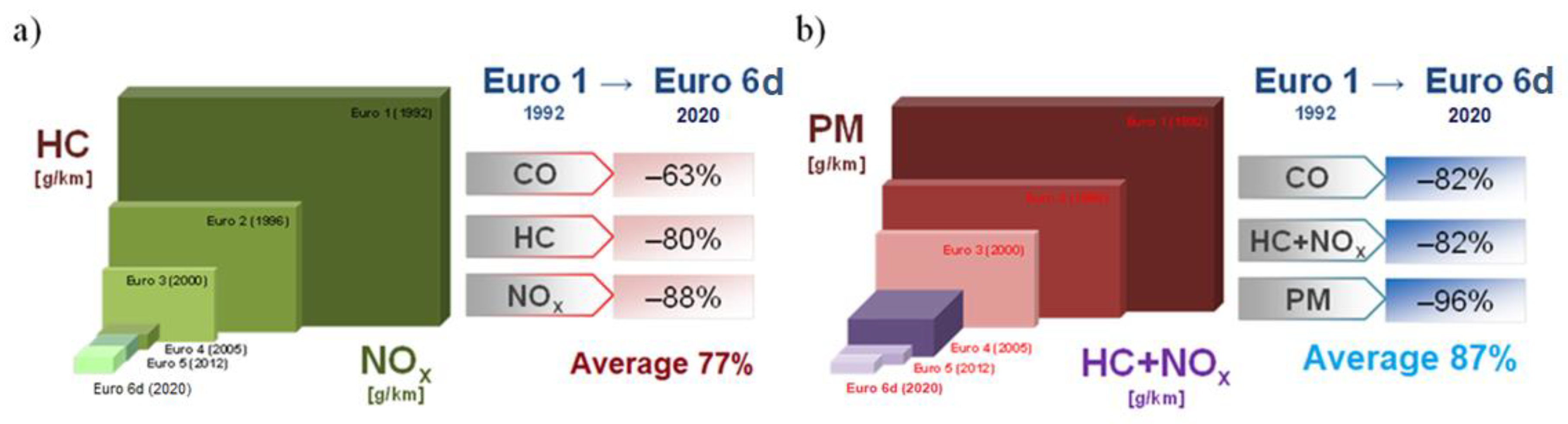
6]. For automotive transport, which, out of all transport modes, is subject to the strictest emission-related regulations, scientists have observed a much more advantageous reduction of exhaust emissions compared to other modes and hence a greater average emission reduction for all modes of transport. The introduction of the Euro 5 and Euro 6 emission standards (
Figure 1) and putting a general focus on the reduction of the emission of greenhouse gases in the European Union have guided research and development works towards the development of new low-emission vehicles, use of alternative fuels, development of new types of engines, and enhancement of the efficiency of those currently manufactured [
7].
The processes of combustion and heat release in combustion engines generate physical and chemical results that largely determine the engine properties. The significant physical results of combustion are mainly the use of energy contained in the fuel [
8], the economy of its utilization, the extent of load of the crankshaft mechanism, and noise. The chemical results mainly pertain to the exhaust gas composition, particularly the concentration of the exhaust components [
9,
10]. Currently, due to environmental requirements, results of exhaust emissions determine the main trends in engine design [
11,
12,
13,
14].
The combustion conditions should ensure a full use of the fuel energy (full and complete combustion) and maintain the cleanliness of the exhaust gas. From the thermodynamic analysis of the thermal cycle of an engine, we know that the efficiency of the heat of combustion is governed by dynamic processes. Full heat generation and its use are therefore contradictory to obtaining low crankshaft dynamic loads at low noise; hence, any technical solution to this problem is a matter of compromise. Another factor challenging the said compromise is the composition of the exhaust gas (compliance requirements) [
15,
16,
17].
Improving environmental performance and fuel economy chiefly depends on the correct organization of combustion [
18,
19]. These improvements heavily depend on the activation energy and rapidness of the chemical reactions, hence the idea of application of an in-cylinder catalyst as a coating to selected components of the combustion chamber with a view to improving the thermodynamic parameters.
The basis for the high efficiency of catalytic converters is as follows: type of washcoat (Oxygen Storage Capacity), proper concentration of noble materials, metal oxides being the promoters, and the properties of the catalytic support, on which the active layer is applied. During the catalytic conversion of exhaust gases, certain chemical reactions occur, some of which are below [
20]:
Aside from the above-presented reactions, depending on the thermodynamic conditions and fuel composition, the following reaction is possible [
21]:
The active (catalytic) layer is a combination of noble metals (different mass shares and configurations): platinum (Pt), palladium (Pd), and rhodium (Rh). The most frequently applied proportion is as follows: Pt:Rh = 5 and Pd:Rh = 5–9 [
22]. Research conducted to increase the efficiency of the catalytic layer and reduce the costs of production has led to the application of tri-component active layers: Pt/Pd/Rh. The masses of the metals used in the construction of a single catalytic converter are platinum 3–7 g, palladium 1.5–5 g, and rhodium 0.8–1.5 g [
23,
24].
2. A Review of Research on In-Cylinder Catalysts
Research on environmental aspects of combustion engines and the positive impact of in-cylinder catalysts on the engine performance and exhaust emissions were already in progress in mid-20th century. The application of a catalytic layer inside the cylinder chiefly aimed at reducing the particulate emissions in diesel engines, which was obtained by minimization of the self-ignition delay [
25,
26,
27,
28]. In other works, the in-cylinder catalyst application (exhaust valve covered with platinum) resulted in a reduction of the emission of carbon monoxide and hydrocarbons in a diesel engine fueled with methanol [
29] and diesel fuel only [
30,
31]. The reduction of nitrogen oxides using an in-cylinder catalyst implies using platinum [
32], but due to the high costs of this application, molybdenum compounds were proposed [
33,
34].
Williams and Schmidt [
35] analyzed the parameters of the ignition initiation in their research on catalytic oxidation of alkanes using rhodium as the active component and observed that a small amount of catalyst introduced to the reactor simulating the conditions inside the engine ensures a reduction of these components. One of their suggestions was that the active components in the combustion chamber start chain reactions at the same time, reducing the chemical delay of the ignition.
The research of Karuppasamy and Mageshkumar [
36] focused on the engine components covered with aluminum, titanium, nickel, and chromium compounds applied with the method of thermal spraying. The authors indicated their most significant conclusions:
One of the most significant aspects is the proper selection of the catalyst. Individual elements or compounds have different temperature ranges at which they are most efficient. Due to the fact of varying efficiencies of the catalytic layers in relation to temperature, it is difficult to ensure sufficiently good efficiency of the catalysts for the entire range of engine loads. This results from the changing temperature inside the cylinder depending on the engine load.
Mutual interactions of the combusted mixture and the catalyst are not limited by the kinetics of the chemical reactions but depend on the speed of supply of the reagents to and from the catalyst during combustion. Introducing swirling and tumbling of the load inside the cylinder improves this situation.
The durability of the catalytic layers depends on the technique of their application. Thermal spraying is the most commonplace and accessible, but it does not ensure durability of the layer. Ionic implantation is indicated as a solution of great potential in this aspect.
The research of Soltic and Bach [
37] examined the problem of in-cylinder catalysts implemented in a spark ignition engine fueled with methane. The underlying reason for the analysis was the problematic oxidation of methane in the catalytic converter. Methane is the most molecularly stable hydrocarbon. The performed investigations did not reveal any significant changes in the concentration of nitrogen oxides in the exhaust, no matter what fuel and excess air coefficient were applied. Similar results were revealed for carbon monoxide, and no changes were observed, irrespective of the type of fuel and the value of the excess air coefficient. As far as the concentration of hydrocarbons is concerned, following the application of a catalytic layer, the authors confirmed the increase of this component irrespective of the applied fuel and value of the excess air coefficient. The adsorptive and desorptive properties of the thermal layer were observed(zirconium oxide). At a high pressure inside the cylinder, the layer absorbs the significant mass of methane (1.74 × 10
−3 g per cylinder). At a low pressure, methane is released directly into the exhaust gas, which results in its higher concentration. The investigations revealed that the thermal and catalytic layers could hold the thermal and mechanical loads occurring inside the cylinder of an engine. Following the application of a catalytic layer onto the pistons, a sizeable increase in the concentration of hydrocarbons in the exhaust was observed. No other changes in the concentrations of the outstanding exhaust components (nitrogen oxides and carbon monoxide) were observed.
3. Research Methodology
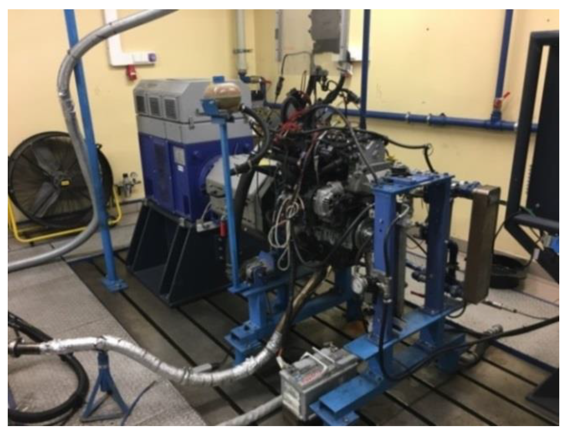
The investigations of the exhaust emissions were carried out on an engine dynamometer, as shown in
Figure 2. The test stand allowed recording of the parameters in a wide spectrum or measurement resolutions while maintaining high sampling frequency (10 Hz). An additional feature of the test stand was the possibility of conditioning the engine consumables and the fuel supply system. The test stand when fully assembled allows storing a large number of parameters related to the operation of the engine and its aggregates. The method of data acquisition and the sampling range and frequency are defined by the operator. During operation, the test stand can be supplemented with additional signals coming from sensors measuring the physical quantities and electric signals but, most of all, from the equipment analyzing the exhaust gas quality. Such an approach to the defined problem allows performing investigations in a wide spectrum of operating conditions.
The investigations were carried out on a Euro 4 1.3 JTD MultiJet diesel engine. The selection of the research object was based on an analysis of the number of engines used in the EU compliant with individual emission standards. The selection of such a research object was motivated by the fact that in the European Union in excess of 50% of vehicles are fitted with such engines. At the same time, the Euro 4 exhaust emission standard was applicable from 1 January 2006 to 1 September 2010, and the average age of a vehicle imported to Poland is 11.5 years (42% of which are diesel engines). Therefore, the most representative engine in Europe and Poland is a diesel one. Another fact is that in this engine, the emission of carbon monoxide and hydrocarbons can be reduced by replacing the glow plug with the modified one. The technical data of the tested object have been presented in
Table 1. The engine was fitted with standard glow plugs, standard glow plugs covered with a catalyst, and prototype elongated catalyst-covered ones [
38,
39].
The investigations presented in this paper focused the key questions in the area of exhaust emissions, one of them being the engine cold start, at which significant emissions take place [
40]. This stage of the engine operation, immediately after the engine start, largely contributes to the total emissions of a vehicle and is increasingly often taken into account in the legislation and also in relation to RDE (Real Driving Emissions) road tests. The investigations were conducted for the engine with no load (idle speed) during engine start and warm up over a time of 1200 s. All gaseous exhaust components and the particle number were measured. We used an exhaust analyzer and a particle counter (their measurement ranges and accuracies complied with the ECE R49 standard, and the particle counter additionally complied with the Particle Measurement Programme requirements (PMP).
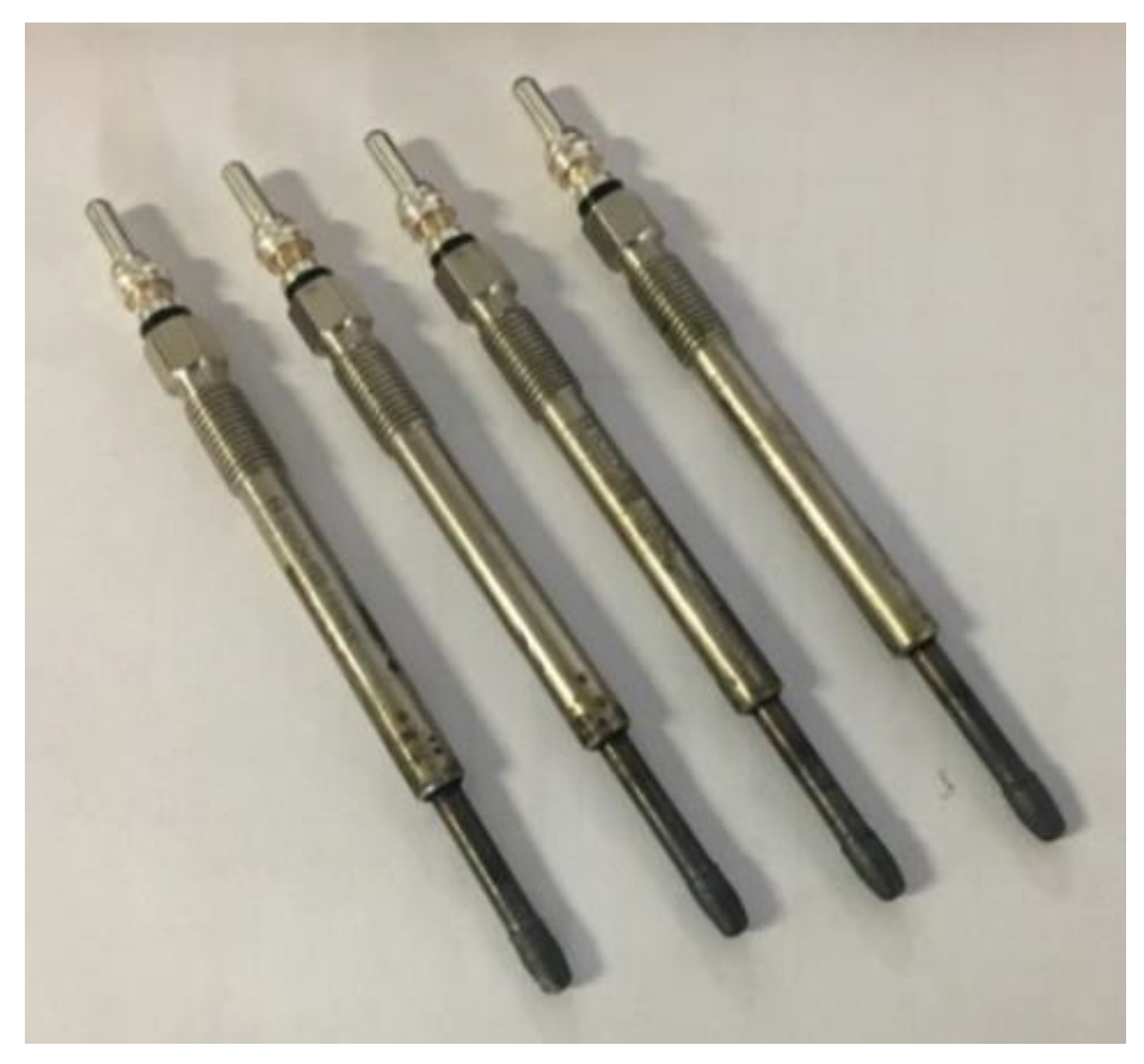
The objects of the investigations were standard glow plugs covered with a catalyst and the prototype ones.
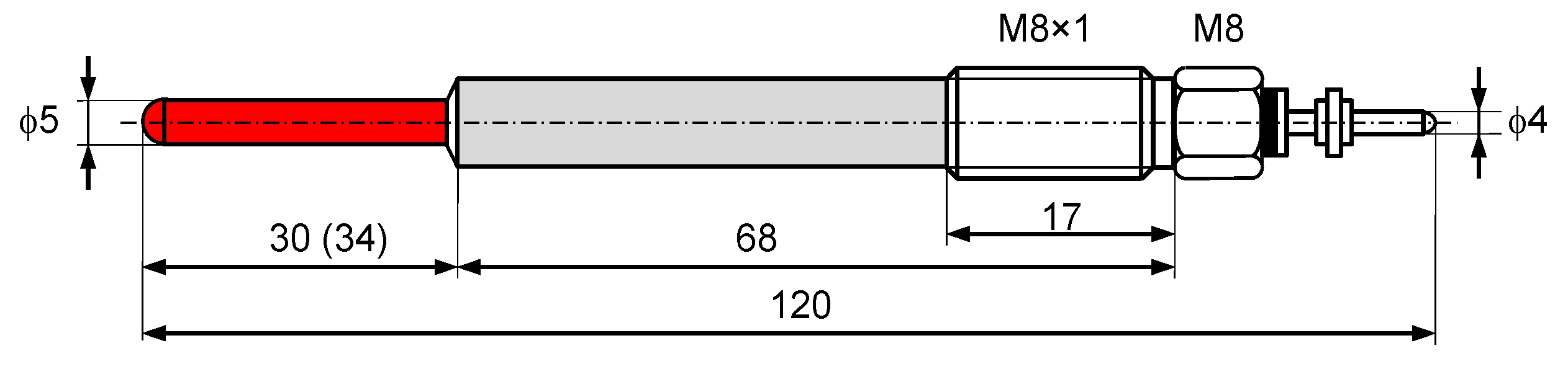
The standard glow plugs had the following parameters (
Figure 3):
The catalytic layer was applied on a standard glow plug. In the first stage, the ceramic layer was applied. The application of the ceramic layer was carried out according to the following procedure. In the first stage, the sprayed component was subjected to blast-abrasive processing with aluminia (the dwell time between sanding and the layer application was approximately 3 h). The application of the sub-layer with a thickness of approx. 0.1 mm was done using nickel-based powder. For this process, a plasma torch was applied, which was also used for the application of the ceramic layer (thickness of 0.1 mm) using zirconium dioxide stabilized with yttrium (grain size 40–60 μm).
In the second stage, on the ceramic layer, a washcoat layer was applied composed of an aluminum oxide in the form of a gel, heated at a temperature of 500 °C. To cover the support, a method of impregnation of platinum nitrate was applied, which was repeated several times. After the described process, the glow plugs were subjected to the thermal processing (350 °C) in order to activate the platinum.
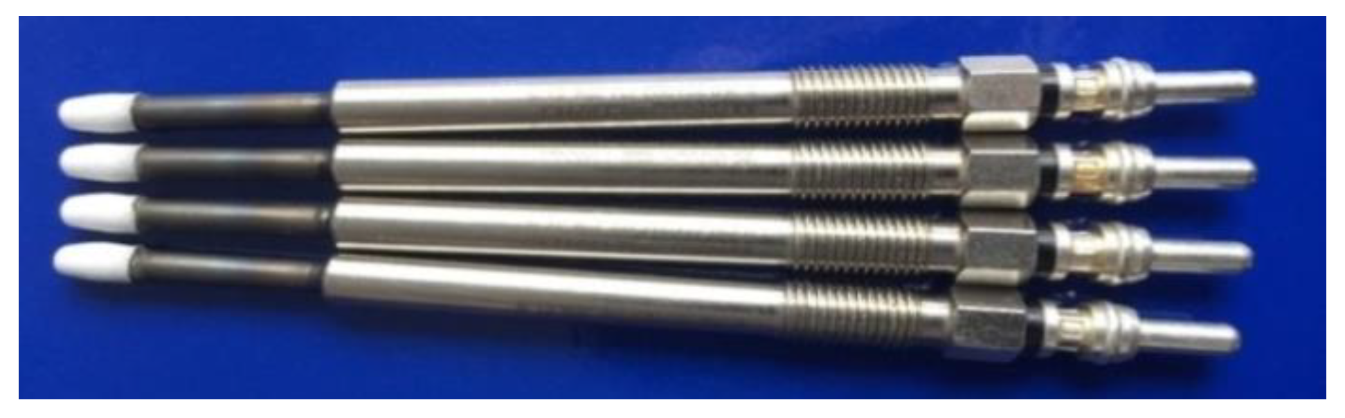
The glow plug with the applied layer is presented in
Figure 4. The next layer was the catalyst (
Figure 5). Platinum was used as the catalytic element, which works mainly during engine start-up and warm-up.
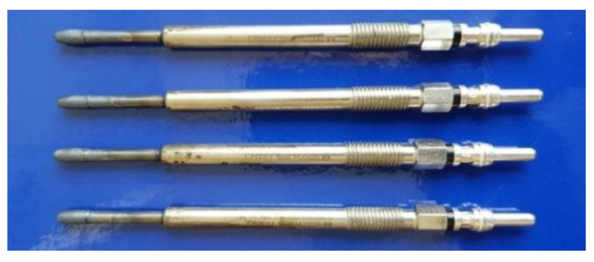
A new solution was the prototype glow plug of the elongated heating part of the length of 34 mm (4 mm longer compared to the previous solutions—
Figure 6).
New prototype glow plugs were longer by 4 mm, which resulted in a 50% increase in the active surface area of the in-cylinder catalyst. The heating part was made from an INOX steel band (18Cr9Ni) with a thickness of 0.05 mm. Such bands are used in catalytic converters with a metal support. This eliminated the ceramic layer that was applied on the standard catalyst-covered glow plug with the heating part of the length of 30 mm. The lack of the ceramic layer allowed reducing the thermal insulation, leading to faster heating of the plugs and a higher operating temperature of the catalytic layer.
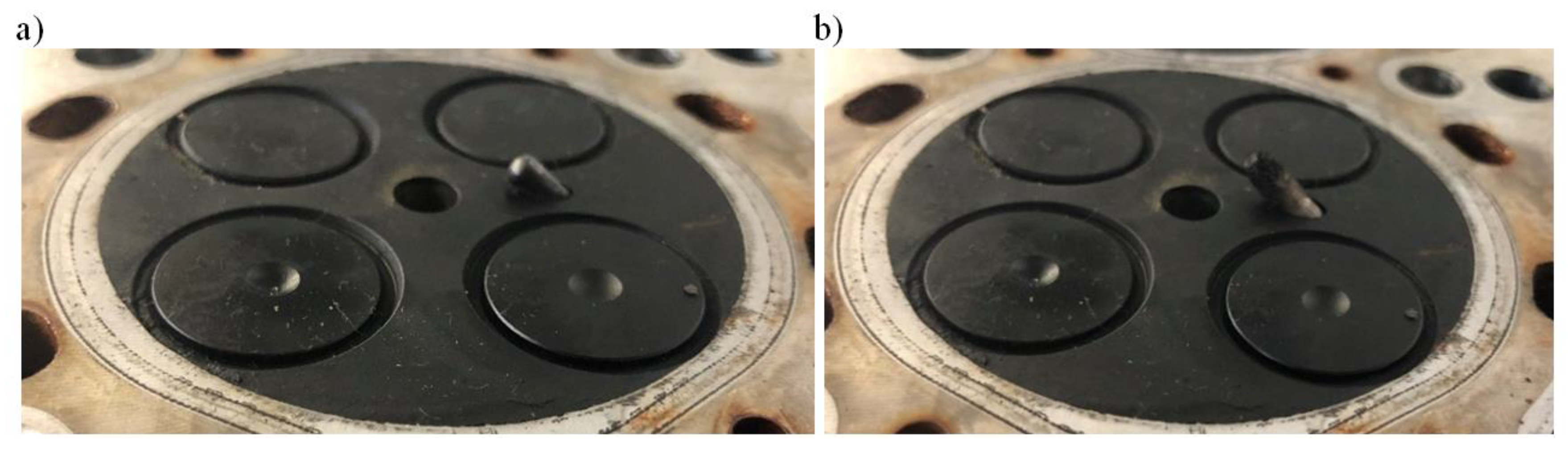
Figure 7 presents a part of the glow plug fitted inside the combustion chamber: standard length plug and prototype plug extended by 4 mm.
4. Results
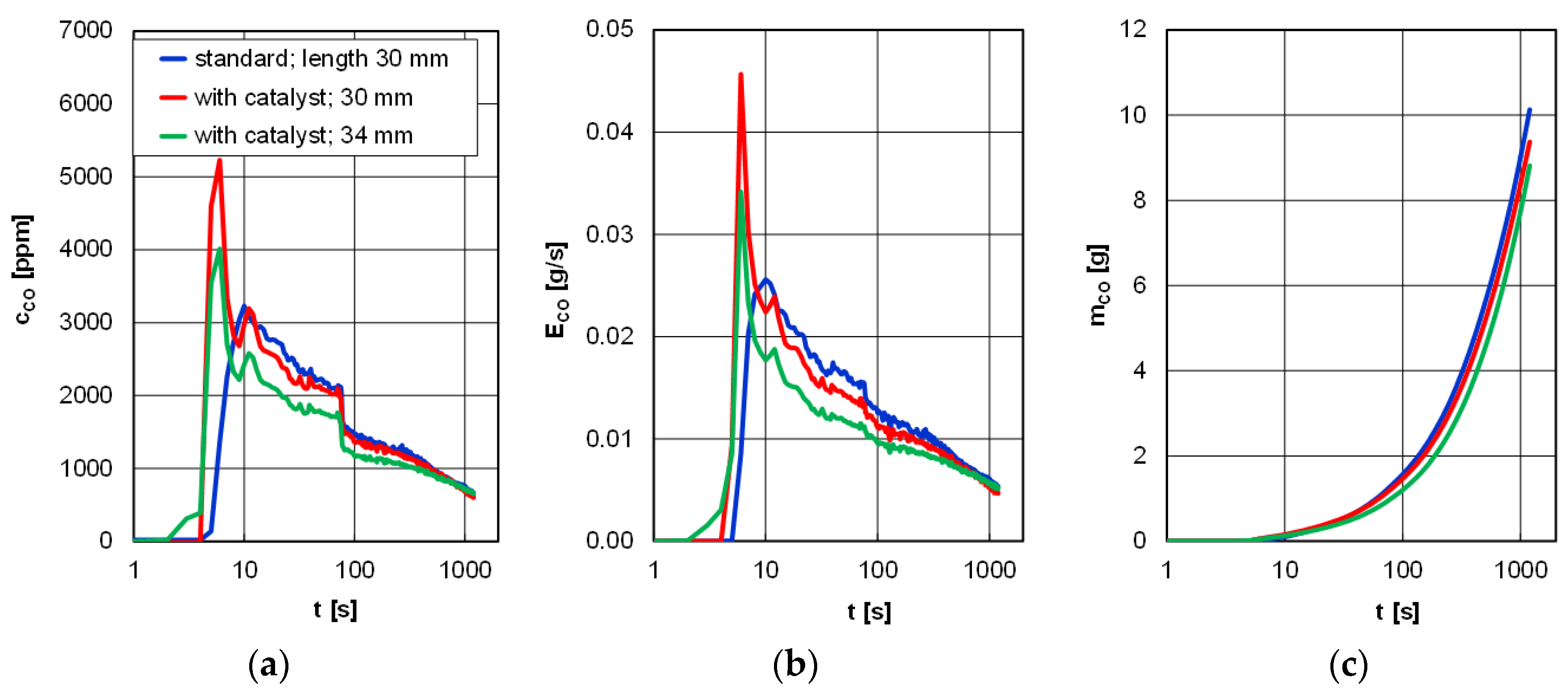
As for the concentration of carbon monoxide, in the entire period of 1200 s, the lowest level was observed for the prototype glow plugs; immediately after the start of the engine, this concentration was 4000 ppm and was 20% lower compared to the shorter, catalyst-covered glow plug. Identical relations were observed for the emission rate of carbon monoxide (exhaust constant mass flow). It is noteworthy that after approximately 600 s no significant differences for both the concentration and the emission rate of carbon monoxide were observed, irrespective of the type of glow plug and the length of its heating catalyst-covered part. As a result, during this test, a mass of carbon monoxide in the range of 8–10 g was obtained (
Figure 8).
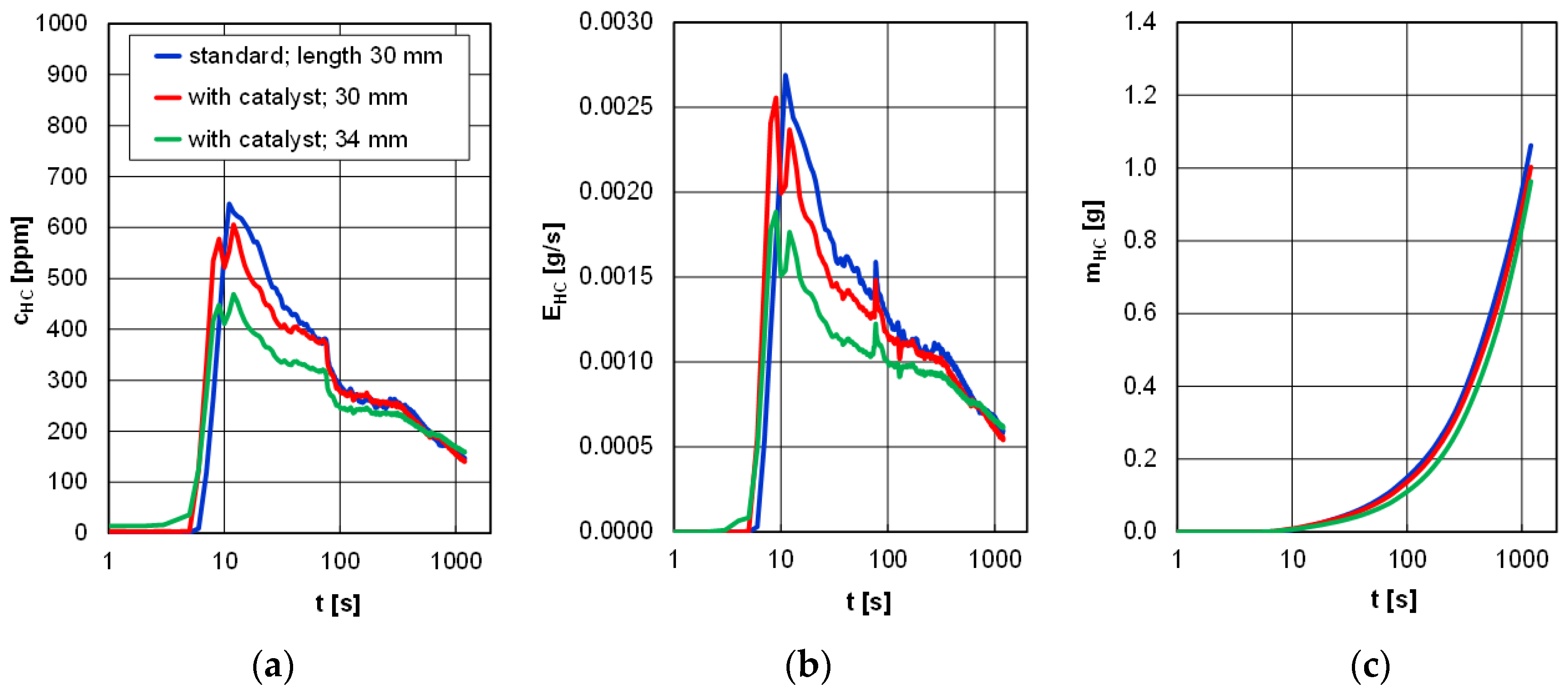
The analysis of the concentration of hydrocarbons rendered similar results. The greatest increase (over 600 ppm) was observed when standard glow plugs were applied, and similar values were obtained in the tests when the catalyst-covered glow plugs with a length of 30 mm were used. For the prototype glow plugs, this value was about 500 ppm. After approximately 100 s, we observed a stabilization of the concentration on the level of 250–300 ppm and its further slow reduction to the level of 150 ppm at the end of the test time. The emission rate of the hydrocarbons was similar in its course to that of the concentration, and the final value was similar for all cases and amounted to approximately 0.0005 g/s. The mass of the hydrocarbons depending on the type of glow plug and its length fell in the range of 0.9–1.1 g (
Figure 9).
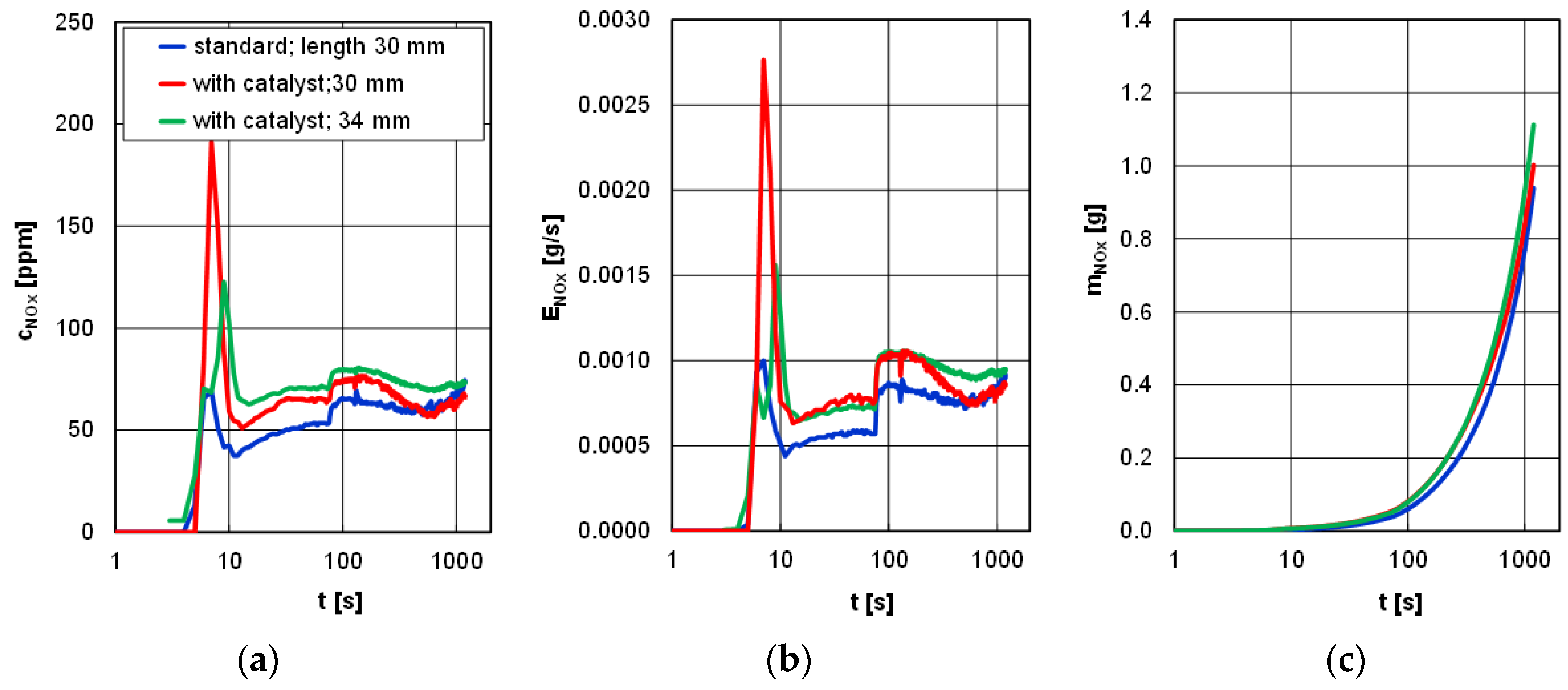
Different changes were observed in the analysis of nitrogen oxides. The lowest increase in the concentration (approximately 120 ppm) but also the highest subsequent value were observed for the prototype glow plugs. The concentration of nitrogen oxides in the first moments after engine start was at the level of 50 to 70 ppm (lower values were observed for standard glow plugs). A similar situation was observed in the analysis of the emission rate of nitrogen oxides, as the highest values are attributed to the prototype glow plugs. After approximately 100 s, a sudden increase in the emission rate of nitrogen oxides was observed from about 0.0005 to 0.001 g/s, caused by the changes in the engine settings (consistent operation of the engine control unit irrespective of the type of glow plugs). The obtained values of the mass of nitrogen oxides for the three types of glow plugs under analysis and their lengths fell in the range of 0.9 to 1.1g (
Figure 10).
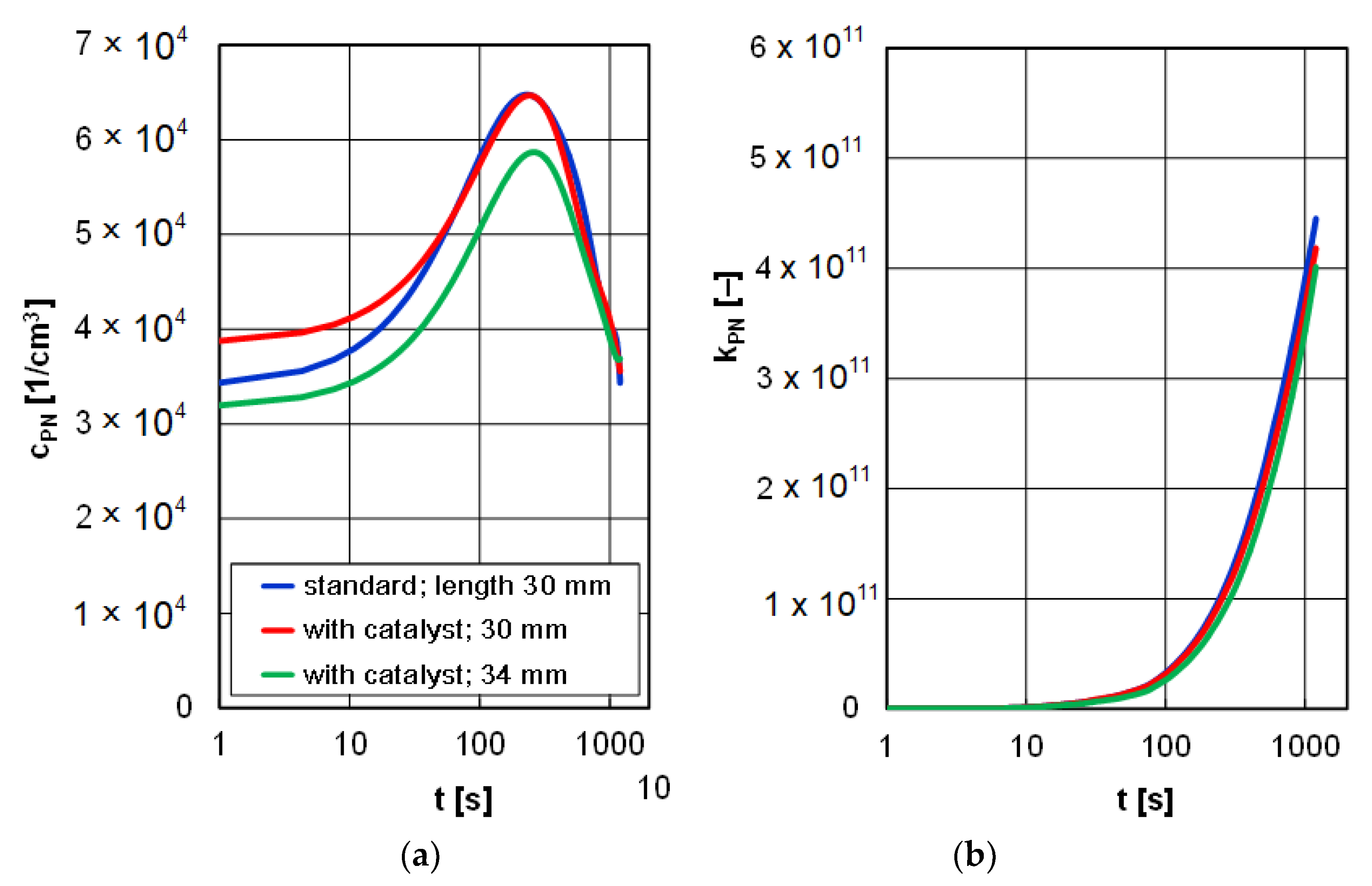
The analysis of the particle number did not provide any varied research results. All the concentration tracings were similar in nature and values. The final value of the particle number allows a correct assessment of the environmental benefits of the glow plugs. The particle number in the entire measurement duration for different types of glow plugs fell in the range of 4 × 10
11 to 5.5 × 10
11 (
Figure 11).
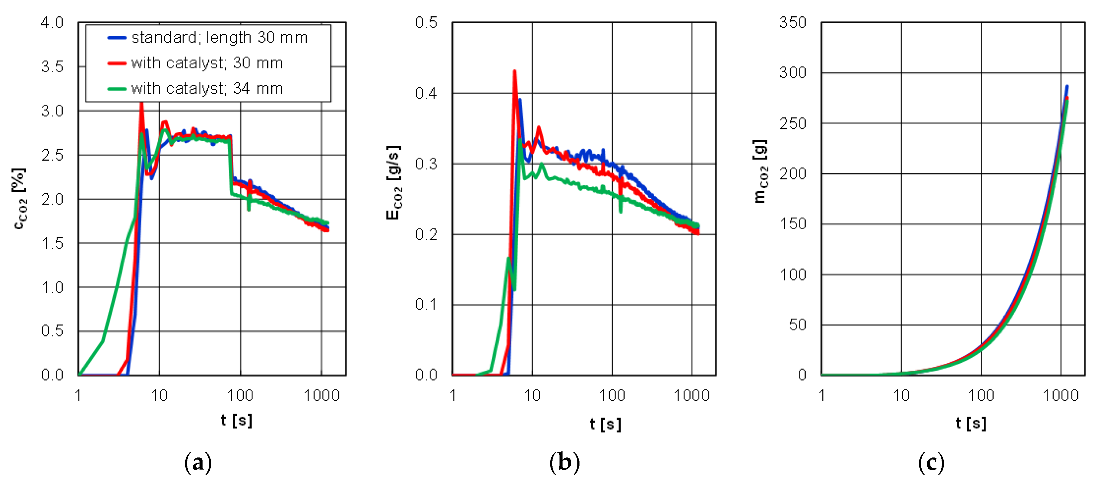
The smallest differences in the analyzed tracings were observed for carbon dioxide for different glow plugs and different lengths of the catalyst-covered ones. The highest unrepeatability occurred in the first 200 s after engine start, while further course of the concentration and emission rate was identical. Also, the emission of carbon dioxide changed only in the range of 270–300 g depending on the type of glow plug and the length of the catalyst-covered one (
Figure 12).
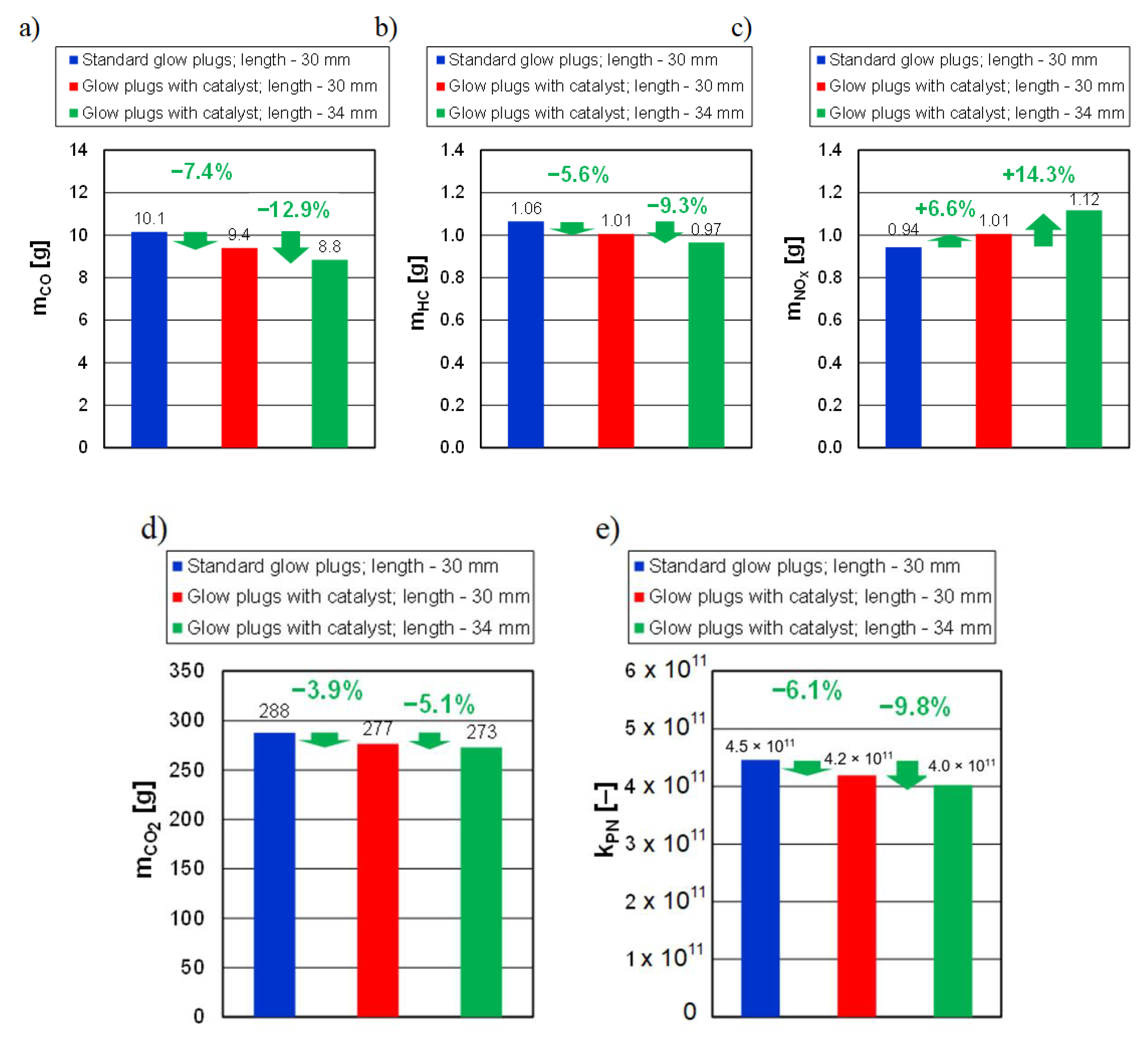
The results below are only shown for comparison for the catalyst-covered glow plugs with lengths of 30 mm and 34 mm (prototype). The investigations of the influence of the length of the catalyst-covered glow plug on the value of the emissions of individual exhaust components during cold start yielded the following results:
- −
catalyst-covered glow plugs, heating part: 30 mm: 9.4 g,
- −
catalyst-covered glow plugs, heating part: 34 mm (prototype): 8.8 g,
- −
catalyst-covered glow plugs, heating part: 30 mm: 1.01 g,
- −
catalyst-covered glow plugs, heating part: 34 mm (prototype): 0.97 g,
- −
catalyst-covered glow plugs, heating part: 30 mm: 1.01 g,
- −
catalyst-covered glow plugs, heating part: 34 mm (prototype): 1.12 g,
- −
catalyst-covered glow plugs, heating part: 30 mm: 277 g,
- −
catalyst-covered glow plugs, heating part: 34 mm (prototype): 273 g,
- −
catalyst-covered glow plugs, heating part: 30 mm: 4.2 × 10¹¹,
- −
catalyst-covered glow plugs, heating part: 34 mm (prototype): 4.0 × 10¹¹.
5. Conclusions
The investigations discussed in the paper pertained to the application of an in-cylinder catalyst allowing a reduction in the exhaust emissions of a diesel engine. Its placement in the combustion chamber, the space where the process of combustion takes place, allows reducing the emission “at source.” The presented research results confirm that the use of an in-cylinder catalyst ensures a several percent reduction in the emissions of carbon monoxide, hydrocarbons, and carbon dioxide as well as in the particle number.
The performed analysis of the emission of the exhaust components confirms the effectiveness of the catalytic processes in the reduction of the said emissions. The efficiency of the in-cylinder catalyst is augmented by the elongation of the catalyst-covered heating part (increased surface area of the catalyst). In the comparison of the exhaust emissions from a cold-started diesel engine using catalyst-covered glow plugs of different lengths of the heating part, the following results were obtained (values refer to the catalyst-covered glow plug of the heating part with a length of 30 mm):
relative reduction of the emission of carbon monoxide by 12.9%;
relative reduction of the emission of hydrocarbons by 9.3%;
relative reduction of the emission of nitrogen oxides by 14.3%,
relative reduction of the particle number by 9.8%;
relative reduction of the emission of carbon dioxide by 5.1%.
The results of the above-described research find application not only in hybrid powertrains where sequential engine activation is used (warm engine, short road portions), but also where engine deactivation is applied after a short period of operation. Such situations are highly related to the content of this paper, where we present a solution of exhaust emission reduction not only in vehicles fitted exclusively with combustion engines but also in hybrid powertrains.
The proposed solution, involving an easily replaceable component, is ideal for retrofitting older vehicles and machines with newer aftertreatment technology to further reduce exhaust emissions. In mass production, the glow plug made from INOX steel, covered with a catalyst and having the heating part extended to 34 mm (platinum) will be only slightly more expensive compared to the standard one.
6. Patents
A patent application resulted from the submitted work. Application number P.425959.
Author Contributions
Conceptualization, M.A.-Z. and J.M.; methodology, J.M. and M.A.-Z.; software, J.P.; validation, J.M., J.P., and M.A.-Z.; formal analysis, J.M.; investigation, M.A.-Z. and J.P.; resources, J.P. and J.M.; data curation, J.P. and M.A.-Z.; writing—original draft preparation, M.A.-Z.; writing—review and editing, J.M.; visualization, M.A.-Z.; supervision, J.M. and J.P.; project administration, J.P.; funding acquisition, J.M., J.P. and M.A.-Z. All authors have read and agreed to the published version of the manuscript.
Funding
This research received no external funding.
Conflicts of Interest
The authors declare no conflict of interest.
References
- Janicka, A.; Kolanek, C.; Walkowiak, W. Ecology of Road Transportation: The Logistic System of End-of-Life Vehicles Recycling; PRINTPAP: Łódź, Poland, 2011. [Google Scholar]
- Commission Regulation (EU) 133/2014 of 31 January 2014 Amending, for the Purposes of Adapting to Technical Progress as Regards Emission Limits, Directive 2007/46/EC of the European Parliament and of the Council, Regulation (EC) No. 595/2009 of the European Parliament and of the Council and Commission Regulation (EU) No. 582/2011. Available online: https://eur-lex.europa.eu/legal-content/EN/TXT/?uri=celex%3A32014R0133 (accessed on 25 October 2020).
- Commission Regulation (EC) 443/2009 of the European Parliament and of the Council of 23 April 2009 Setting Emission Performance Standards for New Passenger Cars as Part of the Community’s Integrated Approach to Reduce CO2 Emissions from Light-Duty Vehicles. 2009. Available online: https://eur-lex.europa.eu/legal-content/EN/TXT/?uri=CELEX%3A32009R0443 (accessed on 26 October 2020).
- Commission Regulation (EU) 582/2011 of 25 May 2011 Implementing and Amending Regulation (EC) No. 595/2009 of the European Parliament and of the Council with Respect to Emissions from Heavy Duty Vehicles (Euro VI) and Amending Annexes I and III to Directive 2007/46/EC of the European Parliament and of the Council. Available online: https://eur-lex.europa.eu/eli/reg/2011/582/oj (accessed on 26 October 2020).
- Commission Regulation (EC) 692/2008 of 18 July 2008 Implementing and Amending Regulation (EC) 715/2007 of the European Parliament and of the Council on Type-Approval of Motor Vehicles with Respect to Emissions from Light Passenger and Commercial Vehicles (Euro 5 and Euro 6) and on Access to Vehicle Repair and Maintenance Information, European Commission (EC), Official J. European Union, L 199. 2008. Available online: https://eur-lex.europa.eu/legal-content/en/ALL/?uri=CELEX%3A32008R0692 (accessed on 26 October 2020).
- Commission Regulation (EC) 715/2007 of the European Parliament and of the Council of 20 June 2007 on Type Approval of Motor Vehicles with Respect to Emissions from Light Passenger and Commercial Vehicles (Euro 5 and Euro 6) and on Access to Vehicle Repair and Maintenance Information, European Commission (EC), Official J. European Union, L 171. 2007. Available online: https://eur-lex.europa.eu/legal-content/EN/ALL/?uri=CELEX%3A32007R0715 (accessed on 25 October 2020).
- Avolio, G.; Brück, R.; Grimm, J.; Maiwald, O.; Rösel, G.; Zhang, H. Super Clean Electrified Diesel: Towards Real NOx Emissions below 35 mg/km. In Proceedings of the 27th Aachen Colloquium Automobile and Engine Technology, Aachen, Germany, 8–10 October 2018. [Google Scholar]
- Kavtaradze, R.; Zeilinger, K.; Zitzler, G. Ignition delay in a diesel engine utilizing different fuels. High Temp. 2005, 43, 951–960. [Google Scholar] [CrossRef]
- Kenecht, W. Diesel engine development in view of reduced emission standards. Energy 2008, 33, 264–271. [Google Scholar] [CrossRef]
- Kozak, M.; Merkisz, J.; Bielaczyc, P. Wpływ właściwości paliwa na emisję szkodliwych składników spalin przez samochód osobowy napędzany silnikiem o zapłonie samoczynnym. Silniki Spalinowe 2005, 1, 19–30. [Google Scholar]
- Haller, P.; Kardasz, P.; Sitnik, L.; Trzmiel, K. Emission of pollutants and energy consumption in life cycle of diesel oil. J. Ecol. Eng. 2013, 14, 4. [Google Scholar] [CrossRef]
- Janicka, A. Toxicity evaluation of exhaust gases in diesel engines using toxicological methods. J. Pol. CIMAC 2014, 9, 2. [Google Scholar]
- Sitnik, L.; Andrych-Zalewska, M. The analysis of the energy balance of the engine powered by diesel oil mixture with butanol. J. KONES 2015, 22, 269–274. [Google Scholar] [CrossRef]
- Walkowiak, W.; Skrętowicz, M. Katalityczne konwertory spalin w motocyklach. In Rozwój, Badania, Rzeczoznawstwo Jednośladów; Ambroszka, W., Wrzecioniarz, P., Eds.; Oficyna Wydawnicza Politechniki Wrocławskiej: Wrocław, Poland, 2016; pp. 37–50. [Google Scholar]
- Bannikov, M.; Draper, P.; Chattha, J.; Vasilev, I.; Gavrilenko, P. Reduction in NOx emission of diesel engines by in-cylinder catalysis. Proc. Inst. Mech. Eng. Part A J. Power Energy 2003, 217, 101–106. [Google Scholar] [CrossRef]
- Huang, Z.; Ren, Y.; Jiang, M. Combustion and emission characteristics of compression ignition engine fuelled Diesel-dimethoxy methane blends. Energy Convers. Manag. 2006, 47, 1402–1415. [Google Scholar] [CrossRef]
- Demuynck, J.; Favre, C.; Bosteels, D.; Randlshofer, G.; Bunar, F.; Spitta, J.; Friendrichs, O.; Kuhrt, A.; Brauer, M. Integrated Diesel System Achieving Ultra-Low Urban and Motorway NOx emissions on the road. In Proceedings of the 40th International Vienna Motor Symposium, Vienna, Austria, 15–17 May 2019. [Google Scholar]
- Andrych-Zalewska, M. Improving the environmental performance of the internal combustion engine by the use of in-cylinder catalyst. Combust. Engines 2017, 168, 1. [Google Scholar]
- Merkisz, J.; Pielecha, J. Nanoparticle Emissions from Combustion Engines. Springer Tracts Transp. Traffic 2015, 8. [Google Scholar] [CrossRef]
- Diesselkamp, R.; Tonkin, R.; Peden, C. Developing multipe-site kinetic models in catalysis simulation: A case study of O2 + 2NO oxidation-reduction chemistry on Pt(100) catalyst crystal facets. J. Catal. 2006, 238, 1. [Google Scholar] [CrossRef]
- Kryl, D.; Koci, P.; Kubicek, M.; Marek, M.; Maunula, T.; Harkonen, M. Catalytic converters for automobile diesel. Engines with adsorption of hydrocarbons on zeolites. Ind. Eng. Chem. Res. 2005, 44, 9524. [Google Scholar] [CrossRef]
- Lambert, C. Critical Materials in Catalysis: Precious vs Base Metal in Automotive Catalyst Systems; Ford Research and Advanced Engineering: Dearborn, MI, USA; Umicore: Brussels, Belgium, 2011. [Google Scholar]
- Anderson, J.; Daley, R.; Christou, S.; Efstathiou, A. Regeneration of thermally aged Pt-Rh/CexZr1_xO2-Al2O3 model three-way catalysts by oxychlorination treatments. Appl. Catal. B. Environ. 2006, 64, 189–200. [Google Scholar] [CrossRef]
- Doleker, K.M.; Yasin, O.D.; Ozkan Nihal, M.; Karaoglanli, A.C. Comparison of microstructures and oxidation behaviors of ytria and magnesia stabilized zirconia thermal barrier coatings (TBC). Mater. Technol. 2018, 52, 315–322. [Google Scholar] [CrossRef]
- Bradstreet, S. Flame sprayed catalyst coatings. Clay Prod. News Ceram. Rec. 1961, 24, 16–17. [Google Scholar]
- Navalihina, M.; Romanovsky, B.; Topchieva, K. Investigation of acidic properties of zeolite by high temperature poisoning technique. Catal. Kinet. 1971, 12/4, 1062–1065. [Google Scholar]
- Samahov, A.; Zaidman, M.; Chizhik, M. Change of Activity of Catalysts during Exploitation; Science, Siberia Branch: Novosibirsk, Russia, 1976. [Google Scholar]
- Vasilev, I.; Gavrilinko, P.; Zvonov, V. Method of Definition of Catalytic Activity of Combustion Chamber Surface of IC Engine. USSR Author Certificate 1312206. Available online: www.impa-ufa.ru (accessed on 15 July 2020).
- Mitchell, W.; Litzinger, T.; Lee, W. Effects of in-cylinder catalysts on combustion and emissions of a D.I. diesel engine fuelled on neat methanol. SAE Pap. Ser. 1992, 920688. [Google Scholar] [CrossRef]
- Winkler, M.; Parker, D. The role of diesel ceramic coatings in reducing automotive emissions and improving combustion efficiency. SAE Pap. Ser. 1993, 930158. [Google Scholar] [CrossRef]
- Wong, V.; Bauer, W.; Kamo, R.; Bryzik, W.; Reid, M. Assessment of thermal barrier coatings for IC engines. SAE Pap. Ser. 1995, 950980. [Google Scholar] [CrossRef]
- Samsonov, G. Catalytic properties of refractory compounds and principles of creation of refractory materials with preassigned properties. Principles of Choice of Catalysts for Heterogeneous. Catalysis 1966, 11, 236–245. [Google Scholar]
- Krylov, O. Catalysis by Non-Metals. Principles of Choice Catalysts; Khimiya: Leningrad, Russia, 1967. [Google Scholar]
- Usov, U.; Skvorzova, E.; Klushnikova, G. Dehydrogenating methylhexane on chromia-alumina and molybdena-alumina catalysts. Neftekhimiya 1963, 3, 320–325. [Google Scholar]
- Williams, K.; Schmidt, L. Catayticautoignition of higher alkane partial oxidation on Rh-coated foams. Appl. Catal. A Gen. 2006, 299, 30–45. [Google Scholar] [CrossRef]
- Karuppasamy, K.; Mageshkumar, M.; Manikandan, T.; Naga Arjun, J.; Senthilkumar, T.; Kumaragurubaran, B.; Chandrasekar, M. The effect of thermal barrier coatings on diesel engine performance. ARPN J. Sci. Technol. 2013, 3, 4. [Google Scholar]
- Soltic, P.; Bach, C. Catalytic piston coating. In Proceedings of the Gas Powered Vehicles, Berlin, Germany, 30 September–1 October 2010. [Google Scholar]
- Andrych-Zalewska, M.; Chłopek, Z.; Merkisz, J.; Pielecha, J. Evaluation of the test drive cycle conditions impact on exhaust emissions from an internal combustion engine. Combust. Engines 2018, 175, 4. [Google Scholar]
- Andrych-Zalewska, M.; Merkisz, J.; Pielecha, J. Problemy pomiarów emisji spalin z pojazdów samochodowych. In Zastosowanie Metod Eksperymentalnych w Motoryzacji. Wybrane Zagadnienia: Praca zbiorowa/red; Wojciech Ambroszko: Wrocław, Poland; Oficyna Wydawnicza Politechniki Wrocławskiej: Wroclaw, Poland, 2020; pp. 145–165. [Google Scholar]
- Schönen, M.; Schaub, J.; Robb, L.; Fiebig, M.; Reinwald, H.; Lindemann, B. Emissions and Fuel Consumption Potential of a Mild-Hybrid-Diesel-Powertrain with a Pre-Turbine Exhaust Aftertreatment. In Proceedings of the 28th Aachen Colloquium Automobile and Engine Technology, Aachen, Germany, 7–9 October 2019. [Google Scholar]
Figure 1.
Admissible on-road exhaust emissions and their reduction in the EU in the years 1992–2020 (period corresponding to the implementation of the Euro 1–Euro 6 standards for passenger vehicles fitted with (
a) spark ignition and (
b) diesel engines [
2,
5,
6].
Figure 1.
Admissible on-road exhaust emissions and their reduction in the EU in the years 1992–2020 (period corresponding to the implementation of the Euro 1–Euro 6 standards for passenger vehicles fitted with (
a) spark ignition and (
b) diesel engines [
2,
5,
6].
Figure 2.
Object of the investigations on an engine test bed.
Figure 2.
Object of the investigations on an engine test bed.
Figure 3.
Dimensions of a standard glow plug.
Figure 3.
Dimensions of a standard glow plug.
Figure 4.
Glow plug with catalytic layer.
Figure 4.
Glow plug with catalytic layer.
Figure 5.
Glow plug with the catalytic layer (heating part—30 mm).
Figure 5.
Glow plug with the catalytic layer (heating part—30 mm).
Figure 6.
Prototype glow plugs with the elongated heating part (34 mm).
Figure 6.
Prototype glow plugs with the elongated heating part (34 mm).
Figure 7.
Heating part of the glow plug inside of the combustion chamber: standard (a), catalyst-covered prototype (b).
Figure 7.
Heating part of the glow plug inside of the combustion chamber: standard (a), catalyst-covered prototype (b).
Figure 8.
Concentration (a), emission rate (b), and emission of carbon monoxide (c) during the tests of a diesel engine depending on the type of glow plugs and the length of the catalyst-covered ones.
Figure 8.
Concentration (a), emission rate (b), and emission of carbon monoxide (c) during the tests of a diesel engine depending on the type of glow plugs and the length of the catalyst-covered ones.
Figure 9.
Concentration (a), emission rate (b), and emission of hydrocarbons (c) during the tests of a diesel engine depending on the type of glow plugs and the length of the catalyst-covered ones.
Figure 9.
Concentration (a), emission rate (b), and emission of hydrocarbons (c) during the tests of a diesel engine depending on the type of glow plugs and the length of the catalyst-covered ones.
Figure 10.
Concentration (a), emission rate (b), and emission of nitrogen oxides (c) during the tests of a diesel engine depending on the type of glow plugs and the length of the catalyst-covered ones.
Figure 10.
Concentration (a), emission rate (b), and emission of nitrogen oxides (c) during the tests of a diesel engine depending on the type of glow plugs and the length of the catalyst-covered ones.
Figure 11.
Concentration (a) and number of particles (b) during the tests of a diesel engine depending on the type of glow plugs and the length of the catalyst-covered ones.
Figure 11.
Concentration (a) and number of particles (b) during the tests of a diesel engine depending on the type of glow plugs and the length of the catalyst-covered ones.
Figure 12.
Concentration (a), emission rate (b), and emission of carbon dioxide (c) during the tests of a diesel engine depending on the type of glow plugs and the length of the catalyst-covered ones.
Figure 12.
Concentration (a), emission rate (b), and emission of carbon dioxide (c) during the tests of a diesel engine depending on the type of glow plugs and the length of the catalyst-covered ones.
Figure 13.
Comparison of the emission of carbon monoxide (a), hydrocarbons (b), nitrogen oxides (c), carbon dioxide (d), and particle number (e) during the tests of a diesel engine depending on the type of glow plugs and the length of the catalyst-covered ones.
Figure 13.
Comparison of the emission of carbon monoxide (a), hydrocarbons (b), nitrogen oxides (c), carbon dioxide (d), and particle number (e) during the tests of a diesel engine depending on the type of glow plugs and the length of the catalyst-covered ones.
Table 1.
Technical data of the tested object.
Table 1.
Technical data of the tested object.
| Technical Data of the Tested Object | Value |
|---|
| Fuel feed | Direct injection |
| Engine capacity | 1.248 dm3 |
| Compression ratio | 18:1 ± 0.4 |
| Supercharging | Constant geometry turbocharger |
| Number of cylinders, valves | In-line R4, 8 valve |
| Injection system, maximum injection pressure | Common rail, 140 MPa |
| Maximum power output at rpm | 51 kW/4000 rpm |
| Maximum torque at rpm | 180 Nm/1750 rpm |
| Oxycat | Yes |
| DPF | No |
| Publisher’s Note: MDPI stays neutral with regard to jurisdictional claims in published maps and institutional affiliations. |
© 2020 by the authors. Licensee MDPI, Basel, Switzerland. This article is an open access article distributed under the terms and conditions of the Creative Commons Attribution (CC BY) license (http://creativecommons.org/licenses/by/4.0/).


