Abstract
Marine current energy is attracting more and more attention in the world as a reliable and highly predictable energy resource. However, conventional proportional integral (PI) control will be sensitive to the numerous challenges that exist in a marine current turbine system (MCTs) such as marine current disturbance, torque disturbance and other uncertain parameters. This paper proposes a fuzzy adaptive backstepping control (F-A-BC) approach for a marine current turbine system. The proposed F-A-BC strategy consisted of two parts. First, an adaptive backstepping control approach with the compensation of disturbance and uncertainty was designed to improve anti-interference of the MCT so that the maximum power point tracking (MPPT) was realized. Then, a fuzzy logic control approach was combined to adjust parameters of an adaptive backstepping control approach in real time. The effectiveness of the proposed controller was verified by the simulation of a direct-drive marine current turbine system. The simulation results showed that the F-A-BC has better anti-interference ability and faster convergence compared to the adaptive backstepping control, sliding mode control and fuzzy PI control strategies under disturbances. The error percentage of rotor speed could be reduced by 3.5% under swell effect compared to the conventional controller. Moreover, the robustness of the F-A-BC method under uncertainties was tested and analyzed. The simulation results also indicated that the proposed approach could slightly improve the power extraction capability of the MCTs under variable marine current speed.
1. Introduction
With the rapid development of the world industry, the demand for energy is increasing [1]. However, traditional energy resources are confronted with depletion, and the consumption of fossil energy represented by oil and coal has brought a series of environmental problems. At present, many countries in the world actively adjust their energy structure and research on the development of renewable energy [2,3]. Among the numerous renewable energy sources, marine current energy is an inexhaustible green energy which hardly harms the environment [4]. The density of marine current is great and the flow of marine current is stable [5]. Therefore, marine current energy can be used for renewable energy production and can operate all over the year continuously [6].
Marine energy conversion systems (MECS) have been developed for many decades to generate power from marine current turbines, and several industrialized large marine turbines have been put into commercial application [7]. Due to the harsh ocean environment, marine current turbines are faced with many challenges including the challenging stall environment, corrosion on the blade surface, shear flow effects and biological attachment to the blade [8,9]. The power harnessed from marine energy by an MCT is proportional to the cube of marine current velocity and the power coefficient of the turbine. When a fixed pitch turbine is applied into MECS, the power coefficient is supposed to be only dependent on the tip speed rotation, which can be controlled by the generator rotor speed to capture the maximum value under variable marine current velocity [10]. However, the stability of MECS is influenced by marine current disturbance, turbine torque disturbance and uncertain parameters of the generator [11,12,13]. Therefore, it is necessary to design robust control strategies to enhance the stability of the MCTs in complex marine conditions.
Classical proportional integral (PI) control is widely applied to engineering areas because it is easy to adjust the parameters of the controller. However, the conventional PI controller is sensitive to disturbances existing in the MCT system which are nonlinear and vary with time, which have an effect on tracking the reference value and maximizing the marine energy [14]. In [15], the PI controller was applied into a current loop control to ensure the quality of the grid-side converter’s output electrical power, which could be seen from the output power characteristics of the marine current turbine system. The active power and reactive power can be regulated by grid-connected control. However, there are a few distortions in the grid-side current under variable marine current speed. In order to improve the transient performance of the PI controller, a fuzzy PI controller that has better performance with adaptive controller gains can be applied to adjust the parameters of the controller online [16,17]. However, this depends, ultimately, on a control algorithm based on the PI controller. If the nonlinearity and uncertainty of the system are serious, the control accuracy of fuzzy PI decreases. In modern control, many advanced control methods are gradually applied to improve the dynamic performance of MCT system under disturbances and uncertainties. The sliding mode control (SMC) is a good choice for nonlinear uncertain systems [18,19]. It is insensitive to disturbances and has fast response time, so it can be applied to replace the PI controller. However, the SMC controller is essentially a discontinuous switch control strategy, which results in a strong chattering phenomenon. In [20], a fuzzy terminal sliding mode control method was designed to capture the maximum marine current energy from a 60 kw marine current turbine. The MCT was put into operation. It can be seen from the experiment results that the proposed control strategy could eliminate generator power fluctuations compared with the conventional second-order SMC method. However, the robustness of the speed loop is degraded under peak marine current velocity because the fuzzy logic controller used in the speed loop control could not make the system track the reference value all the time. In [21], a high order sliding mode controller was applied to overcome the chattering phenomenon and deal with the disturbance caused mainly by the swell effect. However, obtaining high order derivative tended to cause high noise, and the designed controller scarcely analyzed variation of parameters of the permanent magnet synchronous generator (PMSG).
A neural network control strategy can adaptively learn uncertainty and nonlinearity of a system by its own learning processes [22], and a PI controller based on a neural network has good robustness for the system with time delay and parameter variation [23]. However, neural network control requires a large amount of data for training and there exists the phenomenon of overfitting. At present, several control strategies are gradually being applied to restrain the mismatch parameters caused by disturbances and uncertainties. Active disturbance rejection control (ADRC) technology is unnecessary to know the mathematical model, and only needs to compensate the system by observing and estimating the total disturbance of the system in real time [24,25]. In [26], ADRC was applied to improve the system’s dynamic response. However, the ADRC algorithm was relatively complex and there were many parameters that need to be adjusted. In [27], a predictive control based on Luenberger model for induction machine drivers was proposed to compensate the error caused by the mismatched parameters. However, extra resources need to be applied to measure the input signals needed by the torque and flux prediction model, which result in more uncertain parameters. A backstepping control strategy is a good for nonlinear systems to deal with disturbances and uncertainties, and has obvious advantages for control systems with mismatched uncertainties [28,29,30]. At present, the control strategy based on backstepping control has been gradually applied to the motor and generator control field because it can guarantee global stability and has good tracking performance for a feedback system. In [31], an adaptive backstepping controller was proposed to deal with the position tracking problem of a permanent magnet synchronous motor (PMSM) with an unknown load torque. The experimental results showed that the designed controller had better load torque disturbance attenuation capacity. However, the proposed controller barely considered the influence of uncertainty in current loop on the stability of the system. In [32], a control algorithm based on neuro-adaptive backstepping approach was proposed for maximizing energy. The results showed that the proposed controller scheme ensured more precise motor speed tracking in the case of uncertainties and external disturbances. However, the parameters of the proposed control strategy were fixed, which limits the dynamic performance of the generator system when the external disturbances varied in a wide range.
The control strategies mentioned above have the ability to make sure that the MCT system is stable under variable current speed. However, when the MCT is installed at an appropriate depth in a harsh environment there are several problems to be dealt with, such as turbine torque disturbance caused by added mass and robustness control in the current control loop. In this paper, a fuzzy adaptive backstepping controller is proposed for MCTs to deal with disturbances and uncertainties. The proposed control algorithm is consisted of two parts. First, a control strategy based on an A-BC strategy is proposed to make sure that the MCTs is stable under disturbances and uncertainty. In each control loop, the uncertainty and disturbance are estimated and compensated. Then, a fuzzy logic controller is applied to adjust the parameters of the A-BC controller in real time in order to further improve the robustness performance of MCTs. The effectiveness of the proposed controller is verified by a simulation model of a fixed-pitch MCT based on a permanent magnet synchronous generator under disturbances and uncertainties. The paper is organized as follows. In Section 2, the effect of MCT under disturbances and parameters variation of PMSG is analyzed. In Section 3, a fuzzy adaptive backstepping controller based on PMSG is proposed. In Section 4, the proposed F-A-BC scheme is presented and the dynamic performance of the controllers is compared in simulation results. Section 5 gives the conclusion.
2. Problem Description on Disturbances and Uncertainties of MCTs
2.1. Effect of MCT under Disturbances
In this paper, a marine current turbine based on permanent magnet synchronous motor (PMSG) was applied to convert marine energy into electricity. The basic structure of the MCT system as shown in Figure 1 is composed of a turbine blade, PMSG, generator-side converter and grid-side converter. For a horizontal-axis MCT, the mechanical torque of MCT can be expressed by Equation (1).
where is the incoming marine current velocity; is the density of seawater; R is the radius of the turbine; Cp is the turbine power coefficient which is a function of the tip speed ratio (TSR: ) and the pitch angle (). In this paper, the maximum value of Cp is 0.48 corresponding to a TSR of 8.1 for a MCT with fixed-pitch blades ( = 0).
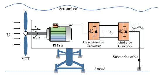
Figure 1.
The general scheme for a (PMSG)-based marine current turbine (MCT) system.
However, the marine current velocity is affected by the swell energy generated by distant storms, which influences the turbine torque according to Equation (1). In addition, an additional torque caused by added mass attaches to the turbine. Therefore, the turbine torque under the disturbances can be expressed by Equation (2).
where is the torque deviation
2.2. Effect of Generator under Uncertainties
The permanent magnet synchronous generator (PMSG) is applied to MCT systems to generate electricity power because of its simple structure and high efficiency. For a PMSG-based MCT system, the turbine is directly connected to the rotor of the generator, which can eliminate the gearbox and reduce maintenance requirements. A surface-mounted PMSG was used in this paper ().
The dynamic model of PMSG in the d-q frame through the Park transformation can be represented as [14]:
where , and , are stator voltages and currents in the d-q frame, respectively; is the stator resistance; , are inductances in the d-q frame, respectively; , are rotor and machine electrical speed, respectively; , are the electromagnetic torque and mechanical torque, respectively; is the machine pole pair number; is the flux linkage produced by the permanent magnets; is the system total inertia and is the viscous friction coefficient.
According to Equation (2) and the mechanical movement equation shown in Equation (3), the rotor speed under turbine disturbance can be described as:
where is the rotor speed deviation.
According to Equations (2) and (4), the mechanical torque and rotor speed are greatly affected by marine current variation. Therefore, the mechanical motion equation can be calculated as:
where represents the lumped disturbance.
The stator resistance will be affected by temperature, and inductance will vary with magnetic saturation, when the MCT drive system operates for a long time, which will influence the stator currents in the d-q frame as shown in Equation (6).
where ; ; and are the deviation of the stator resistance and inductance.
2.3. Rotor Speed Performance under PI Control
For a PMSG-based MCT with fixed-pith blade, the MPPT control based on the TSR method can be realized by controlling the generator rotor speed to make the turbine operate at the optimal tip speed ratio () at any marine current speed [14]. The rotor speed reference for the PMSG is described as the following:
In the classical control scheme, the conventional PI controller can be applied into the speed loop control and current loop control of the generator. Figure 2 shows the rotor speed responses to the rotor speed reference calculated by Equation (7) under different disturbances. It can be seen that the conventional PI controller is unable to keep on tracking the reference value, with an overshoot of about 1 rad/s at the peak marine current, and the rotor speed changes when a sudden turbine torque of 10 Nm is added at 2 s–2.5 s. Controller parameter tuning usually requires accurate plant model and parameters, which may be unavailable or present uncertainties under different operation conditions. This leads to challenges of stable tracking under marine current variation, turbine torque disturbance and uncertain parameters.
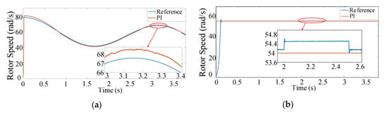
Figure 2.
Rotor speed response under swell effect and turbine torque disturbance. (a) Rotor speed under swell effect; (b) rotor speed under turbine torque disturbance.
It can be seen from Equations (5) and (6) that disturbances and uncertain parameters influence the dynamic performance of speed loop control and current loop control, and the traditional PI controller is unable to track the optimal rotor speed under disturbances. Thus, if high performance of the MCT drive system is needed, the disturbances and parameter uncertainties must be taken into consideration.
3. The Fuzzy Adaptive Backstepping Control (F-A-BC)
The F-A-BC is a combination of adaptive backstepping control and fuzzy logic control, which is consists two parts. First, the A-BC controller is proposed to make the whole system stable under disturbances and uncertainties. Then, the fuzzy logic controller is combined to adjust the parameters of the A-BC controller in real time. The detailed deducing process of the proposed method is described as follows.
3.1. Adaptive Backstepping Control (A-BC) Design
3.1.1. Speed-Loop Control Design
A speed regulator based on adaptive backstepping control was designed to track the rotor speed of the PMSG. The speed tracking error is given by:
where is the reference rotor speed, which can also be considered as the MCT mechanical speed.
By combining Equation (3), the derivative of is given by:
A Lyapunov function is defined as following:
Then, the time derivate of Equation (10) can be deduced as:
In this part, the q-axis current iq is selected as virtual control variable, if is satisfied, and the value of q-axis current iq is deduced as:
According to Equation (5), the parameters variation can be considered as the disturbance η which has influence on the dynamic performance of the speed regulator. Therefore, the reference q-axis current iq can be expressed by the following:
By substituting Equation (13) into Equation (9), the differential of the speed tracking error can be redefined as following:
Then, the Lyapunov function for speed-loop can be reconstructed as:
Therefore, the time derivate of Equation (16) can be expressed by the following:
If , the adaptive law for disturbance η can be deduced by:
3.1.2. Current-Loop Control Design
The current errors of the d-q axis current are defined as:
By combining the Equation (6), the time derivative of Equation (18) is:
In order to get the d-q axis voltage references, a Lyapunov function is constructed as following:
where (i = 1,2,3) are constant coefficient of the disturbance.
Then, the time derivative of Equation (20) can be obtained as following:
If , the MCT generator stator voltages in the d-q frame can be designed as:
The adaptive law of the disturbance and are calculated as the following:
3.2. The Stability Analysis of Proposed Adaptive Backstepping Control
In this section, the stability of the control strategy based on an A-BC controller for a PMSG-based MCT system is analyzed in the Lyapunov theory framework, and the parameters for adaptive gains (ki and γi) can be derived accordingly.
The tracking errors and compensations can be described as:
Then, a Lyapunov function is designed as:
where, .
Then, the time derivative of Equation (25) can be expressed as:
By substituting Equations (14), (17), (21) and (23) into Equation (26), Equation (26) can be deduced as:
Based on Lyapunov theory, if and are satisfied, the global system will be stable and convergent. Therefore, the adaptive gains should follow the following rules:
As seen from Equations (25), (27) and (28), it is clear that the tracking errors in the speed loop and current loop can converge to a small region based on the Lyapunov stability theory. Thus the stability of the MCT system under disturbances and uncertainties is ensured.
3.3. Adjusting the Parameters by Fuzzy Logic Control
The proposed adaptive backstepping control approach can ensure that MCTs are stable under disturbances and uncertainties. However, the fixed parameters of the A-BC controller will limit the dynamic performance of the speed tracking loop. As seen from Equation (13), if the gains ( and ) can be adjusted in real time, the tracking errors in the closed-loop can be converged rapidly to a small region. Fuzzy logic control (FLC) as an intelligence algorithm can be combined to adjust the parameters of the A-BC controller in real time. Therefore, the robustness of the MCTS can be further improved.
The rotor speed error and error change ratio are the inputs of the fuzzy logic controller to adjust gains ( and ) of A-BC controller. The fuzzy domains of outputs are based on the relative optimal parameters ( and ). Therefore, the output parameters and are set in the range of −0.1 to 0.2 and −0.5 to 1.5, respectively. The fuzzy variables are divided into the following: negative big (NB), negative medium (NM), negative small (NS), zero (ZO), positive small (PS), positive medium (PM), and positive big (PB). Table 1 and Table 2 show the rules of FLC for and , and triangular membership functions are used for all fuzzy sets in this paper.

Table 1.
The rules base of Fuzzy Logic Control (FLC) for .
Table 2.
The rules base of FLC for .
The proposed control method based on fuzzy adaptive backstepping control is detailed in Figure 3. It is implemented by the following steps:
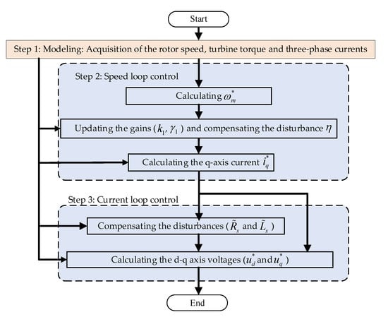
Figure 3.
Detailed flowchart of the proposed fuzzy adaptive backstepping control (F-A-BC) method.
- (a)
- Acquisition of the rotor speed: the turbine mechanical torque and the three-phase stator current of the generator: , , , and are obtained by the sensors and the Park transformation is applied to transform the measured three-phase stator current signals into and .
- (b)
- Speed loop control: first, the rotor speed reference is calculated by the TSR method. then the gains (, ) are updated by the fuzzy logic control and the rotor speed error is calculated to obtain the compensation η of q-axis current. Finally, the q-axis current reference is obtained by the derived speed loop control based on A-BC method.
- (c)
- Current loop control: the tracking errors (, ) and the d-q axis current are calculated to update the compensations (, ) for uncertain parameters then the derivative of the reference voltages (, ) is computed based on the A-BC method.
Consequently, the performance of MCTs can be improved under disturbances and uncertainties. The effectiveness of the proposed controller will be verified by the simulation of a PMSG-based marine current turbine system.
4. Simulation Results and Analysis
In this section, the dynamic performance of the proposed fuzzy adaptive backstepping controller for a PMSG-based MCT whose parameters are shown in the Appendix A is tested and compared. Figure 4 shows the proposed method scheme for MCTs. The parameters of the F-A-BC approach are as follows: = 2000, = 8000, = 7000, = 0.05, = 0.01, = 0.02.
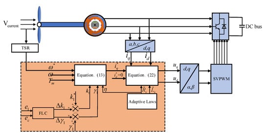
Figure 4.
The fuzzy adaptive backstepping control scheme for MCTs.
4.1. Disturbance Rejection of Swell Effect
Marine current energy mainly refers to the energy generated by the regular seawater flow in submarine channels and straits caused by the tidal energy. However, the long-length ocean waves generated by distant storms make swell energy common, which will inevitably have influence on the MCTs in terms of stability.
Figure 5a,b shows and compares the generator rotor speed response and error percentage under swell effect by different control strategies. It is worth noting that the fuzzy PI controller has a relatively large fluctuation and results in an overshoot of about 2.1 rad/s at a high velocity of marine current, which is 3.4% of the reference rotor speed. The SMC method has a chattering phenomenon near the reference rotor speed, and the error percentage is in the range of 0.5% to 1%, although it can reduce the overshoot. The A-BC method can smooth the rotor speed with an overshoot of 0.25 rad/s at the peak marine current speed. However, the rotor speed disturbance still exists and gradually increases with the marine current velocity. It can be observed from Figure 5b that the proposed F-ABC approach can track the optimal rotor speed and reduce the rotor speed error to less than 0.1% when marine current increases and decreases.


Figure 5.
The rotor speed and rotor speed error responses under swell effect. (a) The rotor speed under swell effect; (b) the error percentage of rotor speed under swell effect.
4.2. Disturbance Rejection of Marine Current and Turbine Torque
In this part, the velocity of marine current is stable and can be regarded as a constant value of 2 m/s. However, it is hard to always make sure that the marine current and turbine torque are smooth due to the complicated marine environment. A sudden drop and rise in velocity of marine current will, respectively, occur at 2–2.7 s and 6–6.7 s, with an additional turbine torque disturbance at 1.5–2 s.
Figure 6 compares the generator power under the swell effect by different controllers. It can be observed that the active power produced by the conventional controllers is significantly influenced by the variable marine current speed and there are significant power fluctuations at the peak of marine current speed. However, the proposed controller can smooth and improve the generator power.
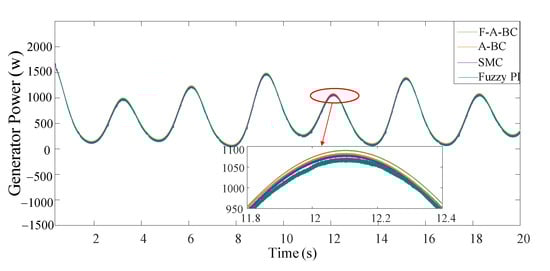
Figure 6.
The generator power under swell effect.
Figure 7a shows the generator speed response to the speed reference calculated by the MPPT strategy based on TSR under marine current and turbine torque disturbance. At first, the marine current velocity is a constant value (2 m/s) and the rotor speed can rapidly follow the optimal value (54 rad/s) with little overshoot. Then, an additional torque disturbance is added into turbine at 1.5 s–2 s. It can be observed from Figure 7b that the turbine mechanical torque disturbance has little influence on rotor speed response and the maximum error percentage is less than 0.02% of the steady-state speed of 54 rad/s. During the abrupt change in marine current velocity at 2–2.7 s and 6–6.7 s, the proposed F-A-BC controller can smoothly track the optimal reference and the rotor speed error is in the range of 0.05% to 0.12% as shown in Figure 7b. When the marine current speed recovers to the constant value at 2.7 s, the proposed method can rapidly track the optimal rotor speed (54 rad/s) within 0.001 s, which proves that the proposed controller is robust against disturbances and has fast convergence.
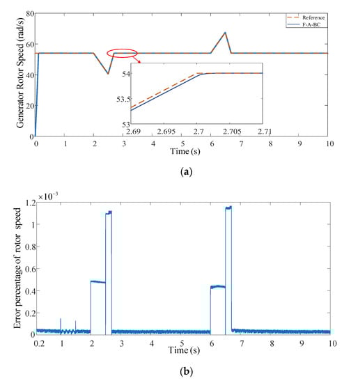
Figure 7.
The rotor speed and the error percentage of the rotor speed under marine current and torque disturbances. (a) The rotor speed response; (b) the error percentage of rotor speed.
In this part, the dynamic performance of the proposed controller under turbine torque disturbance is further analyzed and compared by different controllers. In this paper, an additional turbine torque disturbance expressed by Equation (29) is added at 1.5 s and removed at 2 s under a constant marine current of 2 m/s [33].
Figure 8a shows the generator rotor speed under torque disturbance. During the disturbance stage (1–1.5 s), there are rotor speed fluctuation phenomena for the SMC and fuzzy PI controllers. The SMC and A-BC controllers can reduce overshoot under disturbance condition and can recover quickly after disturbance is removed, compared with the fuzzy PI. It can be observed from Figure 8b that the proposed F-A-BC controller is insensitive to the torque disturbance and can always track the optimal rotor speed with no overshoot. Table 3 compares the dynamic performance of rotor speed under swell effect and torque disturbance by different controllers, which is calculated by ISE (integral of the square error) expressed by Equation (30). A smaller ISE value means it has better ability to suppress error [34].
where e(t) represents the rotor speed tracking error; t1 and t2 are the integration time constants of the researched disturbance stages.
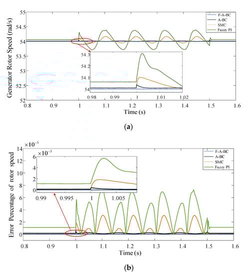
Figure 8.
The rotor speed and rotor speed error responses under turbine torque disturbance. (a) The rotor speed response; (b) the error percentage of rotor speed.
Table 3.
The performance index of rotor speed under different controllers.
4.3. Parameters Variation of MCT Generator Analysis
In the above control simulation systems, the parameters of PMSG are known and fixed. However, the parameters of PMSG will be changed during the operation of the MECS. Therefore, it is necessary to research the influence of parameters variation on dynamic performance of the controllers.
According to Equation (6), the influence of generator resistance variation and inductance variation on stator currents is studied. Figure 9 illustrates the error of q-axis current in different (30 and 250%) and (50 and 150%). It can be seen from Figure 9 that larger parameters variation of resistance and inductance increase current pulses. The error percentages are about 130% and 340% for uncertain parameters under 250% of the resistance and 150% of the inductance. However, the proposed F-A-BC approach is able to rapidly make the q-axis current converge to the stable condition. The performances after 0.12 s are quite similar compared to the original parameter case ( and ), which illustrates the robustness of the proposed current controller.
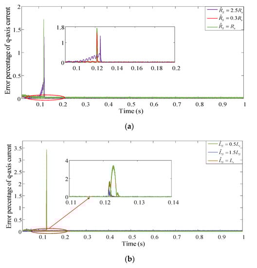
Figure 9.
The error percentage of q-axis current under different stator resistances and inductances. (a) The error percentage of current under different resistances; (b) the error percentage of current under different inductances.
5. Conclusions
The objective of this paper was to propose a control strategy based on a fuzzy adaptive backstepping controller to improve the control performance for a PMSG-based marine current turbine. The MPPT control can be realized by controlling the generator rotor speed to make the turbine operate at the optimal mechanical speed. However, the variable current speed, the additional turbine torque and uncertain parameters can cause disturbances to the MCT system, which makes it hard for conventional controllers to capture the maximum marine current energy.
The method proposed in this paper used a nonlinear adaptive backstepping controller with compensations of disturbance and uncertainty to derive the speed loop control and the current control loop of the MCT system. According to the Lyapunov stability theory, the proposed controller was proved to be globally stable. Meanwhile, the gains of the A-BC approach were adjusted in real time by the fuzzy logic controller because the tracking performance of the speed loop may be degraded under variable marine current speed.
The simulation results clearly confirmed that the proposed F-A-BC method had faster convergence and fewer overshoots compared to the adaptive backstepping control, sliding mode control and fuzzy PI control strategies under various disturbance disturbances. The performance indices calculated by error percentage and ISE indicated that the F-A-BC method had better ability to suppress the lumped disturbances. The error percentage of the rotor speed could be reduced by 3.5% compared to the conventional control. Moreover, the results verified that the uncertain parameters of the generator had little influence on the q-axis tracking performance, which illustrates the proposed approach has strong robustness to the uncertainties. By applying the proposed F-A-BC method to a marine current turbine system, the MPPT control is easily realized because the rotor speed remains operating at the optimal value, and the power extraction capability of the MCTs can be slightly improved under variable marine current speed.
Author Contributions
Conceptualization, X.S. and T.X.; methodology, X.S.; software, X.S.; validation, X.S., T.X. and T.W.; formal analysis, X.S.; investigation, T.W.; resources, T.X.; data curation, X.S.; writing—original draft preparation, X.S.; writing—review and editing, T.W.; visualization, X.S.; supervision, T.X.; project administration, X.S.; funding acquisition, T.W. All authors have read and agreed to the published version of the manuscript.
Funding
The paper was supported by National Natural Science Foundation of China (61673260).
Conflicts of Interest
The authors declare no conflict of interest.
Appendix A
Table A1.
System parameters list.
Table A1.
System parameters list.
| Parameters | Value |
|---|---|
| Sea water density | 1027 kg/m3 |
| Radius of turbine blade | 0.3 m |
| Maximum Cp value for MPPT | 0.48 |
| Stator resistance | 3.3 Ω |
| q-axis inductance | 11.875 mH |
| d-axis inductance | 11.875 mH |
| Permanent magnet flux | 0.1775 Wb |
| Pole pair number | 8 |
| System total inertia | 3.5 kg m2 |
| Generator friction coefficient | 0.0035 N m/rad |
References
- Zhang, Z.; Zhang, Y.; Huang, Q. Market-oriented optimal dispatching strategy for a wind farm with a multiple stage hybrid energy storage system. CSEE J. Power Energy Syst. 2018, 4, 417–424. [Google Scholar] [CrossRef]
- Umoh, K.; Lemon, M. Drivers for and Barriers to the Take up of Floating Offshore Wind Technology: A Comparison of Scotland and South Africa. Energy 2020, 13, 5618. [Google Scholar] [CrossRef]
- Chen, H.; Tang, T.; Aït-Ahmed, N.; Benbouzid, M.E.H.; Machmoum, M.; Zaïm, M.E. Attraction, Challenge and Current Status of Marine Current Energy. IEEE Access 2018, 6, 12665–12685. [Google Scholar] [CrossRef]
- Xie, T.; Wang, T.; Diallo, D.; Christophe, C. A review of current issues of marine current turbine blade fault detection. Ocean Eng. 2020, 218, 108194. [Google Scholar] [CrossRef]
- Forslund, J.; Goude, A.; Thomas, K. Validation of a Coupled Electrical and Hydrodynamic Simulation Model for a Vertical Axis Marine Current Energy Converter. Energies 2018, 11, 3067. [Google Scholar] [CrossRef]
- Goundar, J.N.; Ahmed, M.R. Marine current energy resource assessment and design of a marine current turbine for Fiji. Renew. Energ. 2014, 65, 14–22. [Google Scholar] [CrossRef]
- Zhou, Z.B.; Benbouzid, M.; Charpentier, J.F.; Scuiller, F.; Tang, T.H. Developments in large marine current turbine technologies–A review. Renew. Sustain. Energy Rev. 2017, 71, 852–858. [Google Scholar] [CrossRef]
- Song, K.; Wang, W.Q.; Yan, Y. The hydrodynamic performance of a tidal-stream turbine in shear flow. Ocean Eng. 2020, 199, 107035–107050. [Google Scholar]
- Xie, T.; Wang, T.; Diallo, D.; Razik, H. Imbalance Fault Detection Based on the Integrated Analysis Strategy for Marine Current Turbines under Variable Current Speed. Entropy 2020, 22, 1069. [Google Scholar] [CrossRef]
- Pham, H.; Bourgeot, J.; Benbouzid, M. Comparative Investigations of Sensor Fault-Tolerant Control Strategies Performance for Marine Current Turbine Applications. IEEE J. Ocean. Eng. 2018, 43, 1024–1036. [Google Scholar] [CrossRef]
- Linares-Flores, J.; García-Rodríguez, C.; Sira-Ramírez, H.; Ramírez-Cárdenas, O.D. Robust Backstepping Tracking Controller for Low-Speed PMSM Positioning System: Design, Analysis, and Implementation. IEEE Trans. Ind. Inform. 2015, 11, 1130–1141. [Google Scholar] [CrossRef]
- Lian, C.; Xiao, F.; Gao, S.; Liu, J. Load Torque and Moment of Inertia Identification for Permanent Magnet Synchronous Motor Drives Based on Sliding Mode Observer. IEEE Trans. Power Electron. 2019, 34, 5675–5683. [Google Scholar] [CrossRef]
- Das, S.; Subudhi, B. A H∞ Robust Active and Reactive Power Control Scheme for a PMSG-Based Wind Energy Conversion System. IEEE Trans. Energy Convers. 2018, 33, 980–990. [Google Scholar] [CrossRef]
- Zhou, Z.; Benelghali, S.; Benbouzid, M. Tidal stream turbine control: An active disturbance rejection control approach. Ocean Eng. 2020, 202, 107190–107198. [Google Scholar] [CrossRef]
- Gu, Y.; Liu, H.; Li, W. Integrated design and implementation of 120-kW horizontal-axis tidal current energy conversion system. Ocean Eng. 2018, 158, 339–349. [Google Scholar] [CrossRef]
- Eltag, K.; Aslamx, M.S.; Ullah, R. Dynamic Stability Enhancement Using Fuzzy PI Control Technology for Power System. Int. J. Control Autom. Syst. 2019, 17, 234–242. [Google Scholar] [CrossRef]
- Falahati, S.; Taher, S.A.; Shahidehpour, M. Grid Secondary Frequency Control by Optimized Fuzzy Control of Electric Vehicles. IEEE Trans. Smart Grid 2018, 9, 5613–5621. [Google Scholar] [CrossRef]
- Yang, B.; Yu, T.; Shu, H. Passivity-based sliding-mode control design for optimal power extraction of a PMSG based variable speed wind turbine. Renew. Energy 2018, 119, 577–589. [Google Scholar] [CrossRef]
- Kalla, U.K.; Singh, B.; Murthy, S.S. Slide mode control of microgrid using small hydro driven single-phase SEIG integrated with solar PV array. Renew. Power Gener. IET 2017, 11, 1464–1472. [Google Scholar] [CrossRef]
- Gu, Y.J.; Yin, X.X.; Liu, H.W. Fuzzy terminal sliding mode control for extracting maximum marine current energy. Energy 2017, 90, 258–265. [Google Scholar] [CrossRef]
- Benelghali, S.E.; Benbouzid, M.E.H.; Ahmed-Ali, T.; Charpentier, J.F. High-Order Sliding Mode Control of a Marine Current Turbine Driven Doubly-Fed Induction Generator. IEEE J. Ocean. Eng. 2010, 35, 402–411. [Google Scholar] [CrossRef]
- He, W.; Yan, Z.; Sun, C. Adaptive Neural Network Control of a Flapping Wing Micro Aerial Vehicle with Disturbance Observer. IEEE Trans. Cybern. 2017, 47, 3452–3465. [Google Scholar] [CrossRef]
- Zeng, G.Q.; Xie, X.Q.; Chen, M.R. Adaptive population extremal optimization-based PI neural network for multivariable nonlinear control systems. Swarm Evol. Comput. 2018, 44, 320–334. [Google Scholar] [CrossRef]
- Ma, Y.F.; Liu, J.; Liu, H.; Zhao, S. Active-Reactive Additional Damping Control of a Doubly-Fed Induction Generator Based on Active Disturbance Rejection Control. Energies 2018, 11, 1314. [Google Scholar] [CrossRef]
- Li, S.; Li, J. Output Predictor based Active Disturbance Rejection Control for a Wind Energy Conversion System with PMSG. IEEE Access 2017, 5, 5205–5214. [Google Scholar] [CrossRef]
- Li, S.; Zhang, K.; Li, J. On the rejection of internal and external disturbances in a wind energy conversion system with direct-driven PMSG. ISA Trans. 2016, 61, 95–103. [Google Scholar] [CrossRef]
- Yan, L.; Song, X. Design and Implementation of Luenberger Model-Based Predictive Torque Control of Induction Machine for Robustness Improvement. IEEE Trans. Power Electron. 2020, 35, 2257–2262. [Google Scholar] [CrossRef]
- Ren, H.; Wang, X.; Fan, J.; Kaynak, O. Adaptive Backstepping Control of a Pneumatic System with Unknown Model Parameters and Control Direction. IEEE Acces. 2019, 7, 64471–64482. [Google Scholar] [CrossRef]
- Liu, W.; Xie, F. Backstepping-Based Adaptive Control for Nonlinear Systems with Actuator Failures and Uncertain Parameters. Circuits Syst. Signal Process. 2019, 39, 138–153. [Google Scholar] [CrossRef]
- Roy, T.K.; Mahmud, M.A. Robust Adaptive Backstepping Excitation Controller Design for Higher-Order Models of Synchronous Generators in Multimachine Power Systems. IEEE Trans. Power Syst. 2019, 34, 40–51. [Google Scholar] [CrossRef]
- Sun, X.; Yu, H.; Yu, J.; Liu, X. Design and implementation of a novel adaptive backstepping control scheme for a PMSM with unknown load torque. IET Electr. Power Appl. 2019, 13, 445–455. [Google Scholar] [CrossRef]
- Li, D.; Cai, W.; Li, P.; Xue, S.; Song, Y.; Chen, H. Dynamic Modeling and Controller Design for a Novel Front-End Speed Regulation (FESR) Wind Turbine. IEEE Trans. Power Electron. 2018, 33, 4073–4087. [Google Scholar] [CrossRef]
- Zhang, M.L.; Wang, T.Z.; Tang, T.H.; Benbouzid, M.; Diallo, D. An imbalance fault detection method based on data normalization and EMD for marine current turbines. ISA Trans. 2017, 68, 302–312. [Google Scholar] [CrossRef] [PubMed]
- Singh, V.; Chandra, D.; Kar, H. Optimal Routh approximants through integral squared error minimisation: Computer-aided approach. IEEE Proc. Control Theory Appl. 2004, 151, 53–58. [Google Scholar] [CrossRef]
Publisher’s Note: MDPI stays neutral with regard to jurisdictional claims in published maps and institutional affiliations. |
© 2020 by the authors. Licensee MDPI, Basel, Switzerland. This article is an open access article distributed under the terms and conditions of the Creative Commons Attribution (CC BY) license (http://creativecommons.org/licenses/by/4.0/).