Hierarchical Two-Layer Distributed Control Architecture for Voltage Regulation in Multiple Microgrids in the Presence of Time-Varying Delays

 , ,
, ,  ,
,  and
and 
Abstract
1. Introduction
2. Multiple MicroGrids Modeling
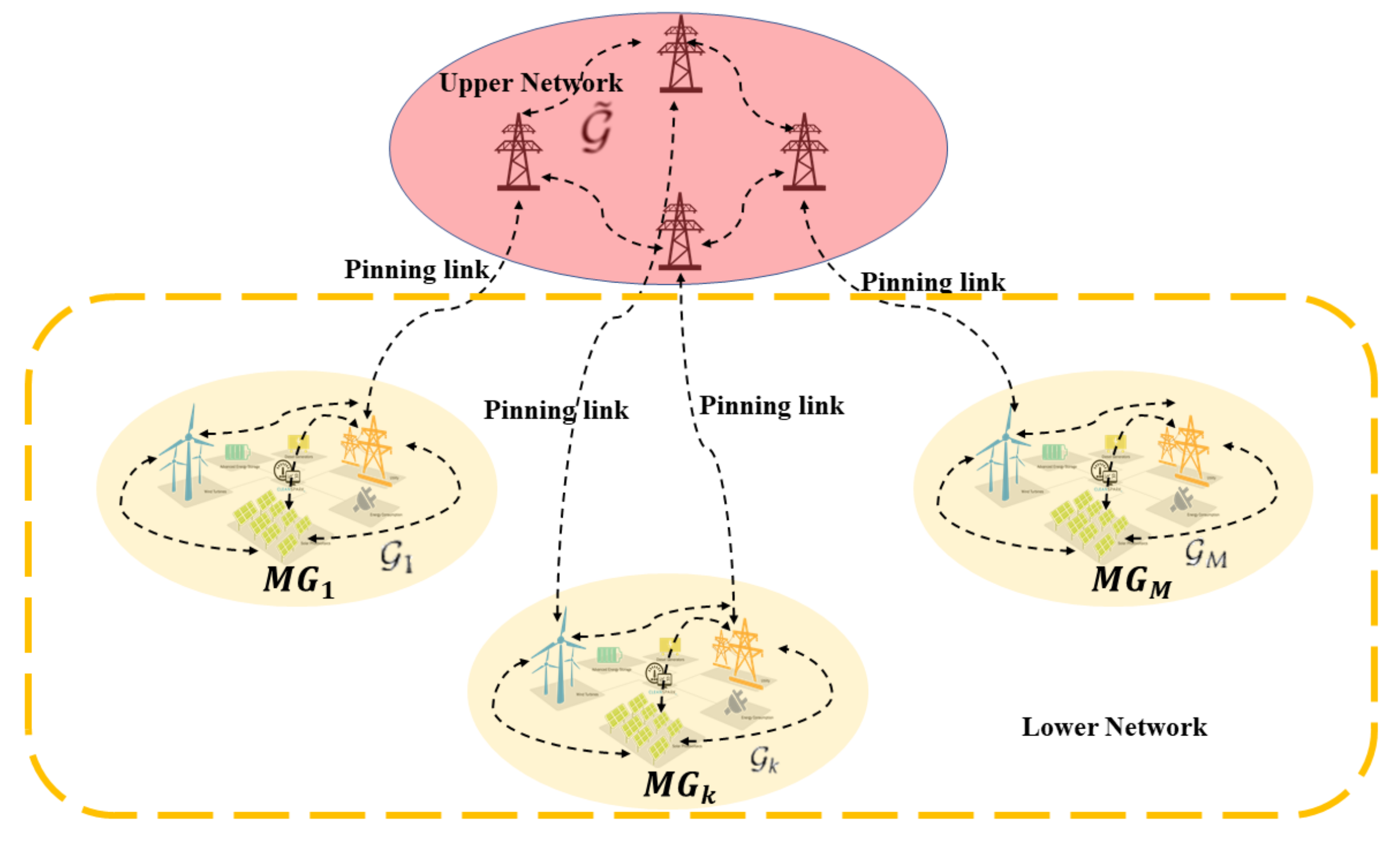
2.1. Double-Layer Communication Network
2.2. Cooperative Smart Agents Dynamics
3. Design of Cluster-Oriented Cooperative Control Strategy
3.1. Driver Generator Nodes Selection
3.2. Inter-Cluster Cooperative Control Strategy Design
| Algorithm 1: Selection of Driver Generator Nodes for the k-th MG based on the Master Stability Functional (MSF) approach. |
 |
3.3. Intra-Cluster Cooperative Control Strategy Design
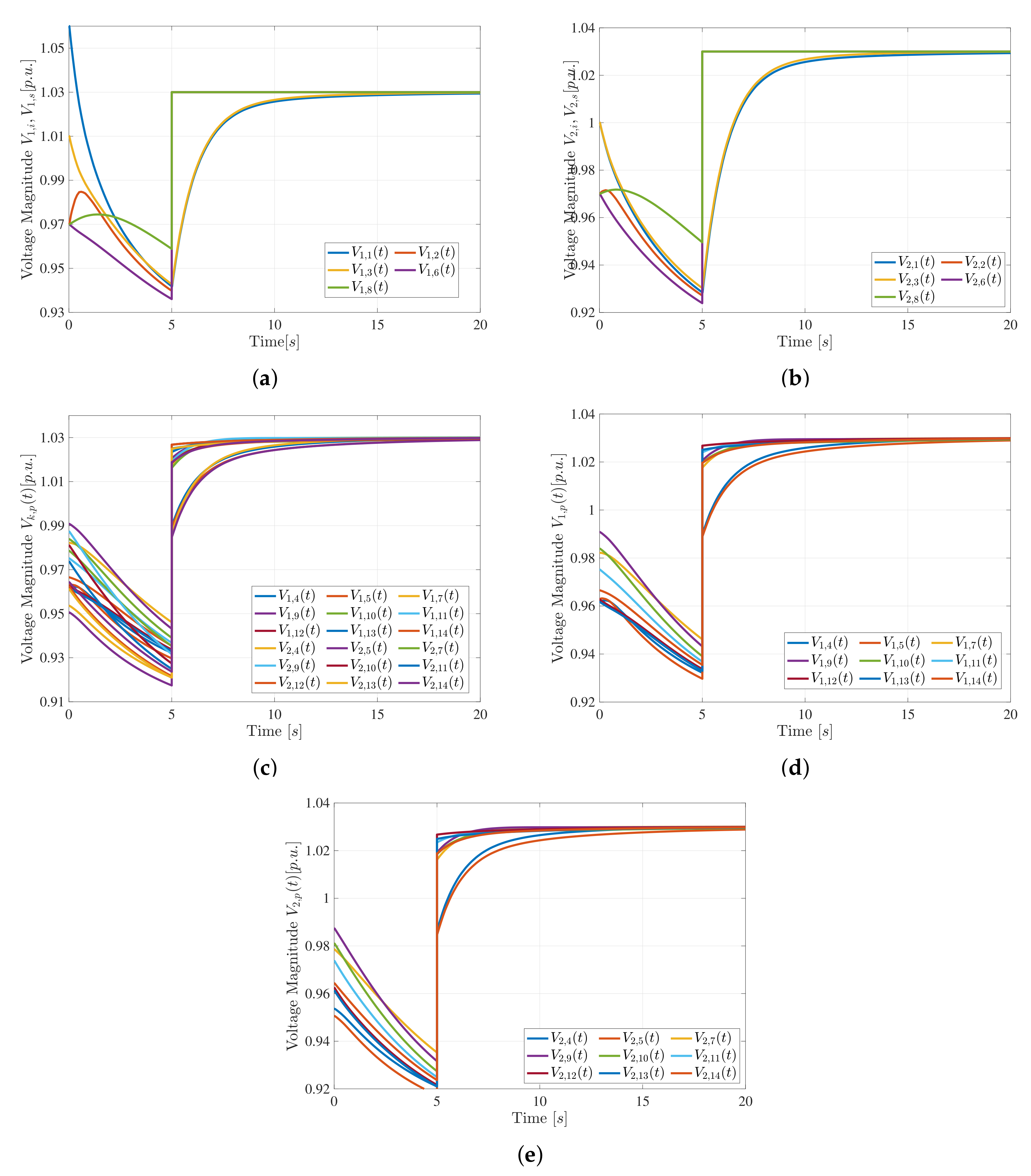
- To design a fully distributed cooperative controller in (2), which, based on local measurements and outdated networked information, regulates the voltage magnitude of the i-th non-pinner generator bus within () in order to reach and maintain the desired reference voltage value computed by the upper control level, i.e.,:where is the voltage magnitude of the generic bus with and is the nominal voltage magnitude of the s-th driver generator node, .
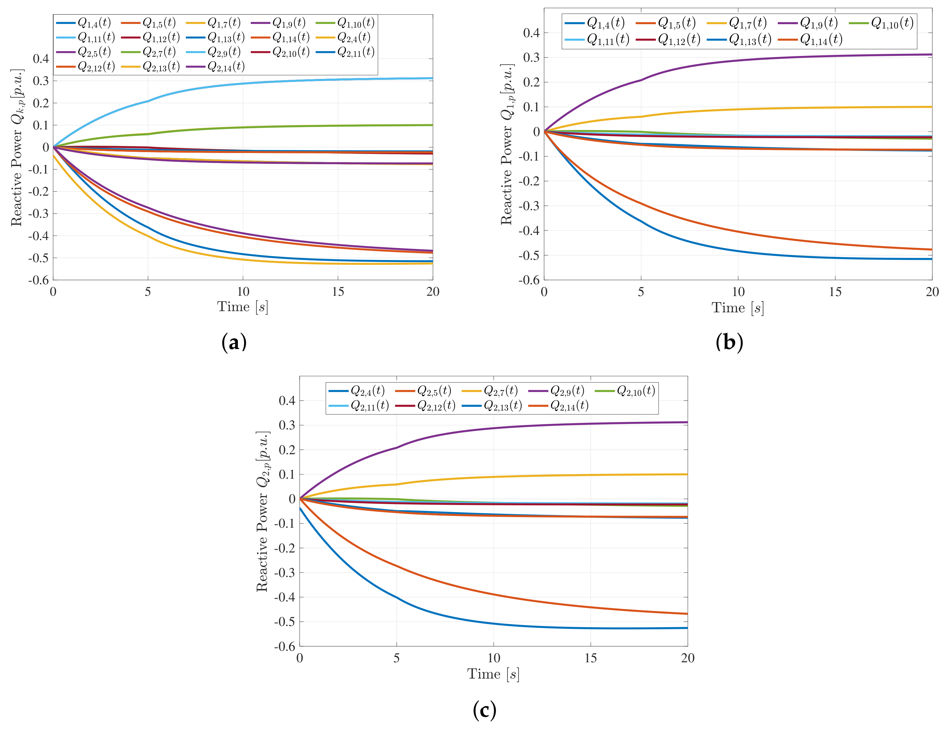
- To design a fully distributed cooperative control protocol in (1), which opportunely drives the reactive power of the capacitor bank p () by updating its voltage magnitude until it reaches the desired reference behavior as imposed by the generators within the ; i.e:where is the voltage magnitude of the generic bus with and is the nominal voltage magnitude of the s-th driver generator node, .
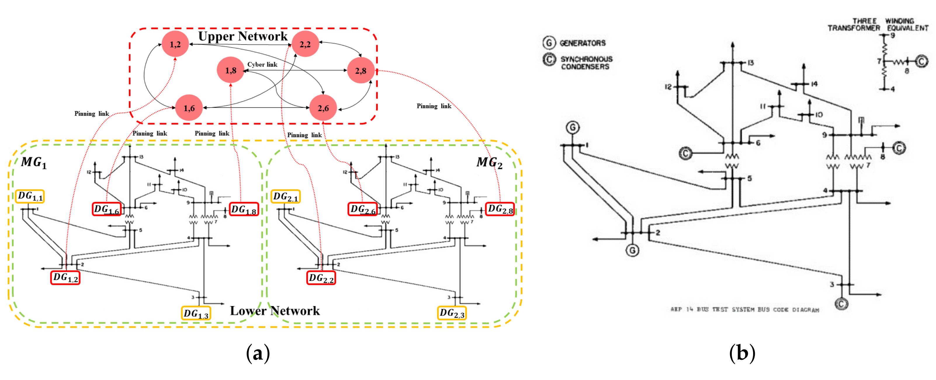
4. Case Study
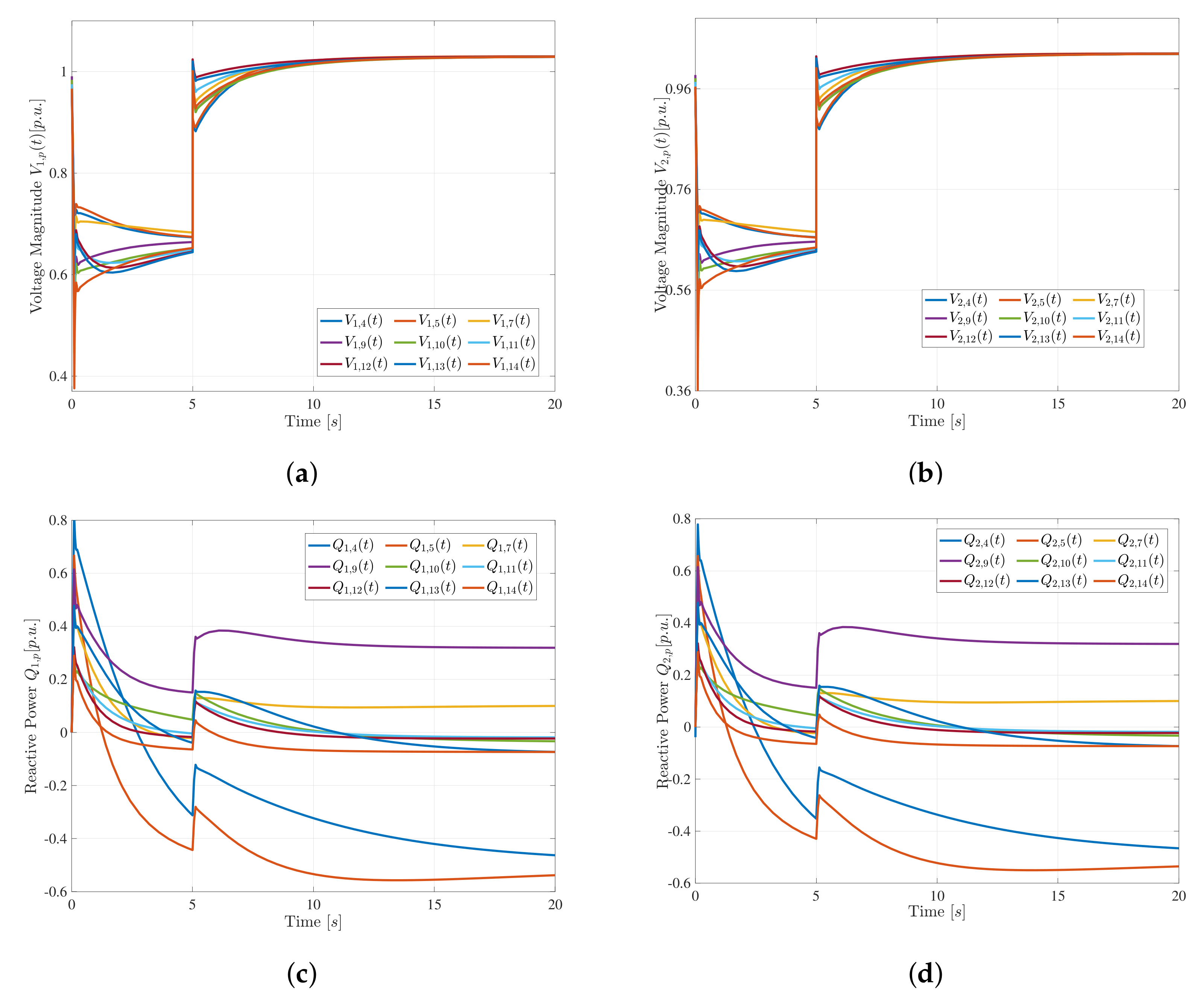
4.1. Nominal Scenario
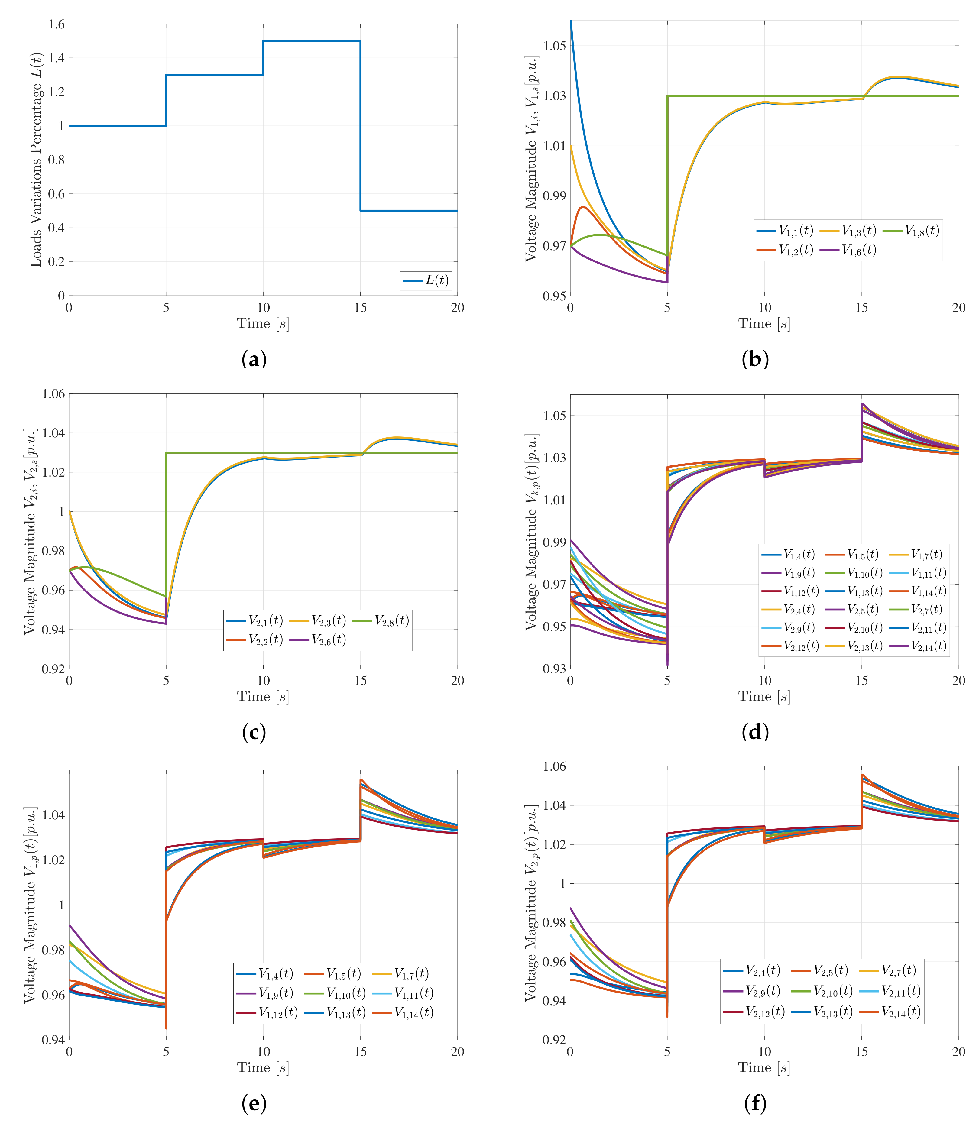
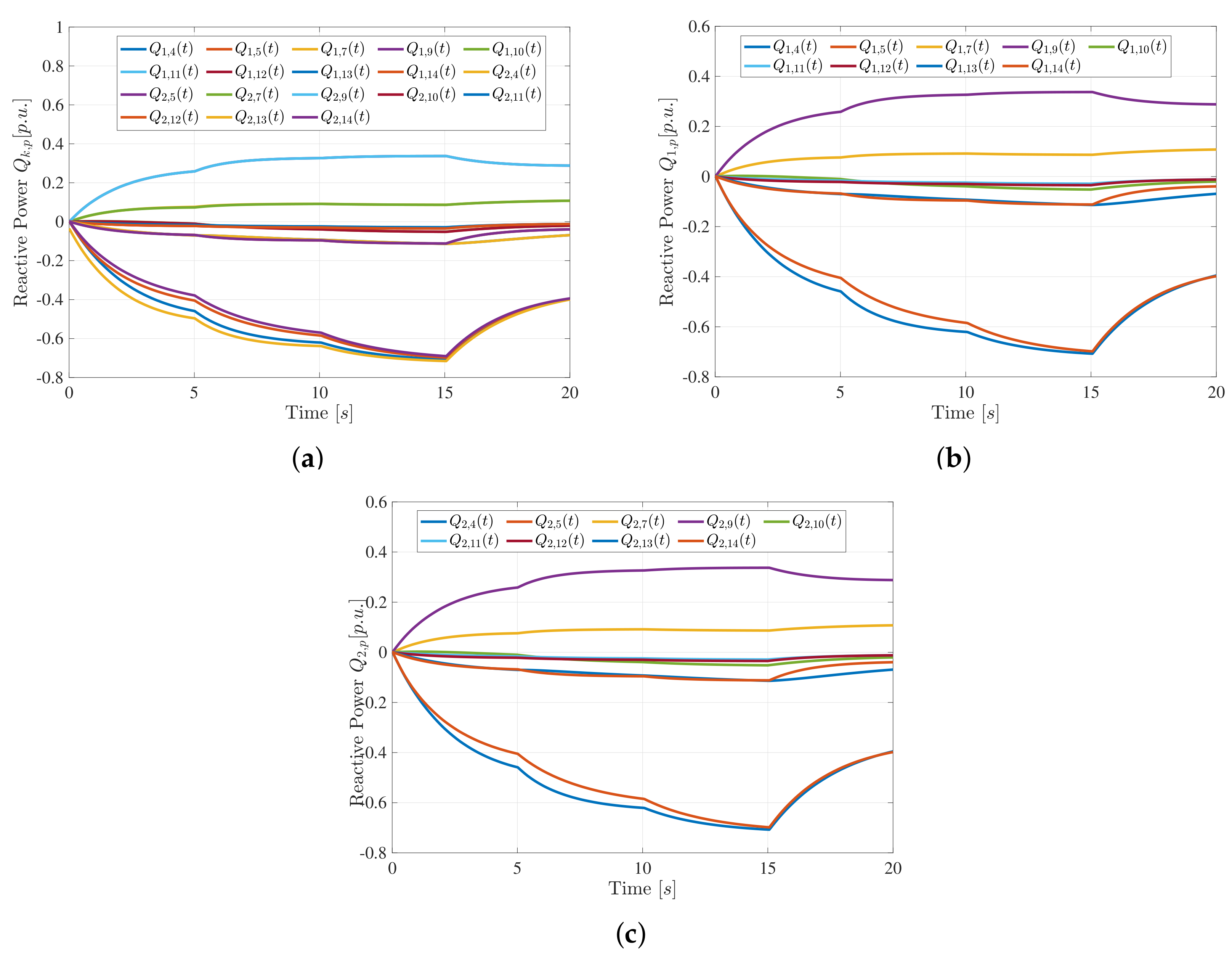
4.2. Load Fluctuations Scenario
4.3. Comparison Analysis
5. Conclusions
Author Contributions
Funding
Conflicts of Interest
Nomenclature
| M | The number of MGs within the MMGs |
| The set of MGs within the MMGs | |
| Number of distributed generators within the k-th MG | |
| The set of distributed generators within the k-th MG | |
| Number of capacitor banks within the k-th MG | |
| The set of capacitor banks within the k-th MG | |
| The set of total buses within the k-th MG | |
| The number of driver generator nodes within the k-th MG | |
| The set of driver generator nodes within the k-th MG | |
| The number of non-pinner generator nodes within the k-th MG | |
| The set of the non-pinner generators nodes within the k-th MG | |
| The number of non-pinner generator nodes plus the capacitor bank within | |
| the k-th MG | |
| The set of nodes within k-MG, involved into the lower cyber layer | |
| n | The number of total driver generator nodes within MMGs |
| The set of all n driver generator nodes within the MMGs | |
| The intra-cluster cyber network of the k-th MG (except for driver generator nodes) | |
| The inter-cluster cyber network | |
| Output Reactive power of the k-th MG | |
| Reactive Power Operating Range of the j-th electrical bus within k-th MG | |
| Reactive power of the p-th capacitor bank within k-th MG | |
| Reactive power of the s-th pinner generator within k-th MG | |
| Voltage magnitude of the p-th capacitor bank within k-th MG | |
| Voltage magnitude of the i-th non pinner generator node within k-th MG | |
| Voltage magnitude of the s-th pinner generator node within k-th MG | |
| Rated voltage magnitude imposed on the MMGs | |
| Nominal Voltage magnitude imposed on the k-th MG |
References
- Andreotti, A.; Caiazzo, B.; Petrillo, A.; Santini, S.; Vaccaro, A. Robust Finite-time Voltage Restoration in Inverter-Based Microgrids via Distributed Cooperative Control in presence of communication time-varying delays. In Proceedings of the 2020 IEEE International Conference on Environment and Electrical Engineering and 2020 IEEE Industrial and Commercial Power Systems Europe (EEEIC/I&CPS Europe), Web Conference, Madrid, Spain, 9–12 June 2020; pp. 1–6. [Google Scholar]
- Sen, S.; Kumar, V. Microgrid control: A comprehensive survey. Annu. Rev. Control 2018, 45, 118–151. [Google Scholar] [CrossRef]
- Sedhom, B.E.; El-Saadawi, M.M.; Hatata, A.Y.; Abd-Raboh, E.H.E. H-Infinity versus model predictive control methods for seamless transition between islanded-and grid-connected modes of microgrids. IET Renew. Power Gener. 2019, 14, 856–870. [Google Scholar] [CrossRef]
- Mumtaz, F.; Bayram, I.S. Planning, operation, and protection of microgrids: An overview. Energy Procedia 2017, 107, 94–100. [Google Scholar] [CrossRef]
- Badal, F.R.; Das, P.; Sarker, S.K.; Das, S.K. A survey on control issues in renewable energy integration and microgrid. Prot. Control Mod. Power Syst. 2019, 4, 8. [Google Scholar] [CrossRef]
- Mahmood, H.; Michaelson, D.; Jiang, J. Accurate reactive power sharing in an islanded microgrid using adaptive virtual impedances. IEEE Trans. Power Electron. 2014, 30, 1605–1617. [Google Scholar] [CrossRef]
- De Azevedo, R.; Cintuglu, M.H.; Ma, T.; Mohammed, O.A. Multiagent-based optimal microgrid control using fully distributed diffusion strategy. IEEE Trans. Smart Grid 2017, 8, 1997–2008. [Google Scholar] [CrossRef]
- Andreotti, A.; Petrillo, A.; Santini, S.; Vaccaro, A.; Villacci, D. A decentralized architecture based on cooperative dynamic agents for online voltage regulation in smart grids. Energies 2019, 12, 1386. [Google Scholar] [CrossRef]
- Fan, Y.; Zhang, C.; Song, C. Sampling-based self-triggered coordination control for multi-agent systems with application to distributed generators. Int. J. Syst. Sci. 2018, 49, 3048–3062. [Google Scholar] [CrossRef]
- Yang, R.; Zhang, H.; Feng, G.; Yan, H.; Wang, Z. Robust cooperative output regulation of multi-agent systems via adaptive event-triggered control. Automatica 2019, 102, 129–136. [Google Scholar] [CrossRef]
- Andreotti, A.; Caiazzo, B.; Petrillo, A.; Santini, S.; Vaccaro, A. Decentralized Smart Grid Voltage Control by Synchronization of Linear Multiagent Systems in the Presence of Time-Varying Latencies. Electronics 2019, 8, 1470. [Google Scholar] [CrossRef]
- Lu, X.; Yu, X.; Lai, J.; Guerrero, J.M.; Zhou, H. Distributed secondary voltage and frequency control for islanded microgrids with uncertain communication links. IEEE Trans. Ind. Inform. 2016, 13, 448–460. [Google Scholar] [CrossRef]
- Gong, P.; Lu, Z.; Lin, J.; Lv, Z.; Hu, L. Distributed secondary control based on cluster consensus of inhibitory coupling with power limit for isolated multi-microgrid. IET Gener. Transm. Distrib. 2019, 13, 4114–4122. [Google Scholar] [CrossRef]
- Robbins, B.A.; Hadjicostis, C.N.; Domínguez-García, A.D. A two-stage distributed architecture for voltage control in power distribution systems. IEEE Trans. Power Syst. 2012, 28, 1470–1482. [Google Scholar] [CrossRef]
- Zhao, B.; Wang, X.; Lin, D.; Calvin, M.M.; Morgan, J.C.; Qin, R.; Wang, C. Energy management of multiple microgrids based on a system of systems architecture. IEEE Trans. Power Syst. 2018, 33, 6410–6421. [Google Scholar] [CrossRef]
- He, M.; Giesselmann, M. Reliability-constrained self-organization and energy management towards a resilient microgrid cluster. In Proceedings of the 2015 IEEE Power & Energy Society Innovative Smart Grid Technologies Conference (ISGT), Washington, DC, USA, 18–20 February 2015; pp. 1–5. [Google Scholar]
- Wu, X.; Xu, Y.; Wu, X.; He, J.; Guerrero, J.M.; Liu, C.C.; Schneider, K.P.; Ton, D.T. A two-layer distributed control method for islanded networked microgrid systems. arXiv 2018, arXiv:1810.08367. [Google Scholar] [CrossRef]
- Che, L.; Zhang, X.; Shahidehpour, M.; Alabdulwahab, A.; Abusorrah, A. Optimal interconnection planning of community microgrids with renewable energy sources. IEEE Trans. Smart Grid 2015, 8, 1054–1063. [Google Scholar] [CrossRef]
- Erol-Kantarci, M.; Kantarci, B.; Mouftah, H.T. Reliable overlay topology design for the smart microgrid network. IEEE Netw. 2011, 25, 38–43. [Google Scholar] [CrossRef]
- Kumar, G.; Sattianadan, D.; Vijayakumar, K. A survey on power management strategies of hybrid energy systems in microgrid. Int. J. Electr. Comput. Eng. (2088-8708) 2020, 10, 1667. [Google Scholar]
- Barra, P.; Coury, D.; Fernandes, R. A survey on adaptive protection of microgrids and distribution systems with distributed generators. Renew. Sustain. Energy Rev. 2020, 118, 109524. [Google Scholar] [CrossRef]
- Lu, X.; Lai, J.; Yu, X.; Wang, Y.; Guerrero, J.M. Distributed coordination of islanded microgrid clusters using a two-layer intermittent communication network. IEEE Trans. Ind. Inform. 2017, 14, 3956–3969. [Google Scholar] [CrossRef]
- Cortes, C.A.; Contreras, S.F.; Shahidehpour, M. Microgrid topology planning for enhancing the reliability of active distribution networks. IEEE Trans. Smart Grid 2017, 9, 6369–6377. [Google Scholar] [CrossRef]
- Ajoulabadi, A.; Ravadanegh, S.N.; Mohammadi-Ivatloo, B. Flexible scheduling of reconfigurable microgrid-based distribution networks considering demand response program. Energy 2020, 196, 117024. [Google Scholar] [CrossRef]
- Han, Y.; Zhang, K.; Li, H.; Coelho, E.A.A.; Guerrero, J.M. MAS-based distributed coordinated control and optimization in microgrid and microgrid clusters: A comprehensive overview. IEEE Trans. Power Electron. 2017, 33, 6488–6508. [Google Scholar] [CrossRef]
- Qu, L.; Zhang, D.; Bao, Z. Active output-voltage-sharing control scheme for input series output series connected DC–DC converters based on a master slave structure. IEEE Trans. Power Electron. 2016, 32, 6638–6651. [Google Scholar] [CrossRef]
- Wang, Y.; Nguyen, T.L.; Xu, Y.; Tran, Q.T.; Caire, R. Peer-to-Peer Control for Networked Microgrids: Multi-Layer and Multi-Agent Architecture Design. IEEE Trans. Smart Grid 2020. [Google Scholar] [CrossRef]
- Lai, J.; Lu, X.; Yu, X.; Monti, A. Cluster-oriented distributed cooperative control for multiple AC microgrids. IEEE Trans. Ind. Inform. 2019, 15, 5906–5918. [Google Scholar] [CrossRef]
- Couto, M.; Lopes, J.P.; Moreira, C. Control strategies for Multi-Microgrids islanding operation through Smart Transformers. Electr. Power Syst. Res. 2019, 174, 105866. [Google Scholar] [CrossRef]
- Lu, X.; Lai, J.; Yu, X. A Novel Secondary Power Management Strategy for Multiple AC Microgrids with Cluster-Oriented Two-Layer Cooperative Framework. IEEE Trans. Ind. Inform. 2020. [Google Scholar] [CrossRef]
- Pecora, L.M.; Carroll, T.L. Master stability functions for synchronized coupled systems. Phys. Rev. Lett. 1998, 80, 2109. [Google Scholar] [CrossRef]
- Jalili, M.; Sichani, O.A.; Yu, X. Optimal pinning controllability of complex networks: Dependence on network structure. Phys. Rev. E 2015, 91, 012803. [Google Scholar] [CrossRef]
- Su, H.; Wang, X. Pinning Control of Complex Networked Systems: Synchronization, Consensus and Flocking of Networked Systems via Pinning; Springer: Berlin/Heisenberg, Germany, 2013. [Google Scholar]
- Amani, A.M.; Jalili, M.; Yu, X.; Stone, L. Finding the most influential nodes in pinning controllability of complex networks. IEEE Trans. Circuits Syst. II: Express Briefs 2017, 64, 685–689. [Google Scholar] [CrossRef]
- Fridman, E. Introduction to Time-Delay Systems: Analysis and Control; Springer: Berlin/Heisenberg, Germany, 2014. [Google Scholar]
- Hase, Y. Handbook of Power System Engineering; John Wiley & Sons: Hoboken, NJ, USA, 2007. [Google Scholar]
- Zimmerman, R.D.; Murillo-Sánchez, C.E. MATPOWER 6.0 user’s manual. Power Syst. Eng. Res. Cent. 2016. [Google Scholar]
- Fiengo, G.; Lui, D.G.; Petrillo, A.; Santini, S. Distributed leader-tracking adaptive control for high-order nonlinear Lipschitz multi-agent systems with multiple time-varying communication delays. Int. J. Control 2019, 2, 1–13. [Google Scholar] [CrossRef]
- Horalek, J.; Svoboda, T.; Holik, F. Analysis of the wireless communication latency and its dependency on a data size. In Proceedings of the 2016 IEEE 17th International Symposium on Computational Intelligence and Informatics (CINTI), Budapest, Hungary, 17–19 November 2016; pp. 000145–000150. [Google Scholar]
- Zhang, X.M.; Han, Q.L.; Yu, X. Survey on recent advances in networked control systems. IEEE Trans. Ind. Inform. 2015, 12, 1740–1752. [Google Scholar] [CrossRef]
- Fiengo, G.; Lui, D.G.; Petrillo, A.; Santini, S. Distributed robust output consensus for linear multi-agent systems with input time-varying delays and parameter uncertainties. IET Control Theory Appl. 2018, 13, 203–212. [Google Scholar] [CrossRef]
- Petrillo, A.; Salvi, A.; Santini, S.; Valente, A.S. Adaptive synchronization of linear multi-agent systems with time-varying multiple delays. J. Frankl. Inst. 2017, 354, 8586–8605. [Google Scholar] [CrossRef]
- Petrillo, A.; Pescape, A.; Santini, S. A secure adaptive control for cooperative driving of autonomous connected vehicles in the presence of heterogeneous communication delays and cyberattacks. IEEE Trans. Cybern. 2020. [Google Scholar] [CrossRef]


| Initial Conditions for the Multiple MG Cluster System | |
|---|---|
| Voltage magnitude of generator bus | ; ; ; |
| ; | |
| Cluster Voltage-rated value | |
| Reactive power of capacitor bank bus | ; |
| ; | |
| ; | |
| ; | |
| ; | |
| ; | |
| ; | |
| ; | |
| ; | |
| Control Gains | |
| Control gains | |
| Control gains | |
| Control gains |
Publisher’s Note: MDPI stays neutral with regard to jurisdictional claims in published maps and institutional affiliations. |
© 2020 by the authors. Licensee MDPI, Basel, Switzerland. This article is an open access article distributed under the terms and conditions of the Creative Commons Attribution (CC BY) license (http://creativecommons.org/licenses/by/4.0/).
Share and Cite
Andreotti, A.; Caiazzo, B.; Petrillo, A.; Santini, S.; Vaccaro, A. Hierarchical Two-Layer Distributed Control Architecture for Voltage Regulation in Multiple Microgrids in the Presence of Time-Varying Delays. Energies 2020, 13, 6507. https://doi.org/10.3390/en13246507
Andreotti A, Caiazzo B, Petrillo A, Santini S, Vaccaro A. Hierarchical Two-Layer Distributed Control Architecture for Voltage Regulation in Multiple Microgrids in the Presence of Time-Varying Delays. Energies. 2020; 13(24):6507. https://doi.org/10.3390/en13246507
Chicago/Turabian StyleAndreotti, Amedeo, Bianca Caiazzo, Alberto Petrillo, Stefania Santini, and Alfredo Vaccaro. 2020. "Hierarchical Two-Layer Distributed Control Architecture for Voltage Regulation in Multiple Microgrids in the Presence of Time-Varying Delays" Energies 13, no. 24: 6507. https://doi.org/10.3390/en13246507
APA StyleAndreotti, A., Caiazzo, B., Petrillo, A., Santini, S., & Vaccaro, A. (2020). Hierarchical Two-Layer Distributed Control Architecture for Voltage Regulation in Multiple Microgrids in the Presence of Time-Varying Delays. Energies, 13(24), 6507. https://doi.org/10.3390/en13246507