Abstract
With the problem of environmental pollution and energy shortage becoming more and more serious, the fuel efficiency of automobile engines has attracted much attention, and variable valve technology is one of the important technologies to solve this problem. A novel fully variable valve actuation (FVVA) system based on a brushless direct current motor (BLDCM) is designed to achieve fully variable valve adjustment. The system uses a crank-moving guide rod mechanism to convert the rotary motion of the BLDCM into the linear motion of the valve. The fully variable valve system can realize real-time continuous adjustment of valve operating parameters through the motion control of BLDCM, including variable valve timing, variable valve opening duration, and variable lift. A BLDCM and a transmission mechanism for the FVVA system is designed in this paper. In order to better analyze the performance of the system, a dynamic model is established. Then, a three closed-loop control method is adopted to realize position control of the valve. Finally, a complete system model is established to verify the theory conclusions. The results show that the system can realize fully variable valve adjustment.
1. Introduction
As one of the important components of the engine, the valve train has the advantages of improving engine power, economy, and reducing harmful emissions. It has a wide range of research prospects and application prospects [1]. Traditional valve trains use a fixed mechanical structure to drive the cams. The internal combustion engine can only obtain the best performance under certain operating conditions, not all operating conditions.
The variable valve train can realize flexible control of valve parameters. Its advantage is that it can provide a suitable valve opening and closing time or lift under different operating conditions of the engine. It better meets the requirements of engine power, economy, and exhaust emission at different velocities and different loads to improve the overall performance of the engine [2,3].
The variable valve trains are usually divided into cam valve trains and camless valve trains. This includes cam valve trains, such as the VTEC dual camshaft valve timing system developed by Honda. This cam valve train can only achieve extreme adjustment; it cannot meet the requirements of the best performance of the engine under all working conditions. There are many limitations [4,5,6]. The camless variable valve can be driven by electro-magnetic, electro-hydraulic, or electro-pneumatic actuations.
The biggest feature of the electro-magnetic system is the spring system [7,8], which is shown in Figure 1a. In this article, it is referred to as an electromechanical camless valve (EMCLV) system. The valve starts in the middle position, and the valve is opened or closed by energizing different coils. This system can realize valve timing, but the valve lift cannot be changed, and the seat speed is difficult to control. To solve this problem, an electromagnetic linear actuator valve mechanism is proposed, which is rigidly connected to the valve through the linear actuator and directly drives the valve to achieve variable lift of the valve. The system detects the position of the valve through a linear displacement sensor. However, now, the market does not have a suitable speed sensor to detect the velocity of the valve; therefore, the valve seat velocity is still difficult to control.
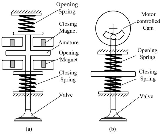
Figure 1.
The electromechanical camless valve system: (a) Solenoid controlled (b) Motor controlled
The electro-hydraulic system [9,10,11] is quite simple in concept. Due to the elastic characteristics of hydraulic fluid, the system has the characteristics of a liquid spring, which has a certain cushioning effect on the valve seat, and the seating velocity is low. However, the electro-hydraulic system usually uses engine oil as the hydraulic fluid, and its viscosity changes greatly by temperature, so the performance drops sharply at low temperatures. At the same time, it is not easy for hydraulic systems to achieve good energy efficiency, because their kinetic energy cannot be recovered well when the valves decelerate. Moreover, the response speed of the electro-hydraulic system is not high, and the sealing is difficult to solve.
The electro-pneumatic system [12] is similar to the electro-hydraulic type, and it replaces the electro-hydraulic driven medium with gas. The inertia of gas motion is small, but the compressibility of gas has become its fatal flaw as a driving medium.
In addition, the authors of [13] proposed a new transmission scheme based on motor-driven valves. The crankshaft is not directly connected to the camshaft; instead, the rotary motor directly drives the camshaft to drive the rocker arm to control the valve. During the camshaft rotation, the angular velocity of the camshaft is reduced and increased to produce different valve timings. Its mechanical complexity is relatively high, and the valve lift cannot be adjusted continuously, but the camshaft system has good performance in terms of seating velocity. In the literature [14], Parlikar T.A designed a disc-shaped cam with functions similar to traditional cams, and made a non-linear profile as needed. The author modeled the system and did related experiments to change the valve action by controlling the operation of the motor. It has better flexibility.
The traditional motor-driven valve mechanism adopts a cam and spring structure (see Figure 1b), and the system needs to overcome a large spring force when opening or closing the valve, so the energy consumption is high. Its mechanical complexity is high, and the valve lift is not adjustable. However, the motor-driven systems are outstanding in transient time and seating velocity. It will be used as the benchmark for this FVVA system. However, unlike it, the FVVA system does not apply to the camshaft system but directly drives the valve through the transmission mechanism, with relatively low mechanical complexity. At the same time, the spring structure is eliminated without having to overcome the larger spring force. Different from the electromagnetic valve drive mechanism, the FVVA system uses a relatively mature rotary encoder to obtain the absolute position of the valve, such as an absolute photoelectric encoder, which can obtain the velocity of the valve through the position. This is advantageous to better control the valve seat velocity. Vibration and noise during engine operation can be reduced by reducing the impact of the valve on the seat. In addition, due to the expansion effect of the valve rod after being heated, the traditional camshaft valve driving system adopts the method of reserving valve clearance to solve the problem. Due to the existence of valve clearance, the valve distribution mechanism will produce a certain impact and noise when working. In order to solve this contradiction, some systems adopt a hydraulic tappet column without valve clearance. However, the hydraulic tappet structure has high machining precision, and cannot be adjusted after wear and tear, and can only be replaced directly, so it is rarely used. In the FVVA system, the valve is directly connected to the transmission mechanism, and the influence of the thermal expansion of the valve rod can be solved by recalibration when the valve is closed.
This article aims to propose a novel fully variable valve actuation system based on BLDCM to improve fuel efficiency, including motor design, optimized transmission mechanism design, and control strategy design. First, the overall design scheme according to the system requirements is proposed. Then, the structural design and development are completed based on the scheme. Finally, a complete system model is established to achieve the position of the three closed loop control. The results show that this scheme can realize the full flexible valve adjustment.
2. System Overview
2.1. System Requirements
In order to achieve the performance of the traditional valve drive system, the system needs to meet the following basic requirements:
- In order to ensure adequate intake and exhaust, the FVVA system needs to provide a maximum valve lift of 8 mm in general, and it also needs to have the function of adjusting the valve lift.
- In order to ensure that the internal combustion engine runs at high load and high velocity, the valves need to be able to move to a specified displacement in a short time. For the FVVA system, the important indicator is the transition time of valve opening or closing. The transition time is defined as the time from 5% to 95% of the valve opening or closing position.
For the calculation of the transition time, the engine is generally operated at the maximum velocity = 6000 r/min. The maximum time allowed for valve opening or closing is defined as follows:
where the maximum continuous crank angle of the valve is 288°, so = 4 ms, and the valve transition time needs to be controlled within 4 ms.
- 3.
- During the valve closing process, if the seating velocity exceeds a certain range, it is very likely to cause an impact between the valve seat and the valve with the valve rebound. This will easily cause the valve to fail to close in time and affect the ventilation function. It is generally believed that the maximum allowable valve seat velocity is 0.3 m/s [15,16].
2.2. System Structure
As shown in Figure 2, the FVVA system is mainly composed of an actuator, a valve control unit, a power drive module, and a signal feedback module. The actuator is composed of a BLDCM and a crank moving-guide rod mechanism. The BLDCM, as a power source for driving the valve movement, it is used to provide power. The crank moving-guide rod mechanism includes a rotating arm and a valve connector, which is used to connect the BLDCM and the valve. It can transform the rotary motion of the BLDCM into the linear motion of the valve.
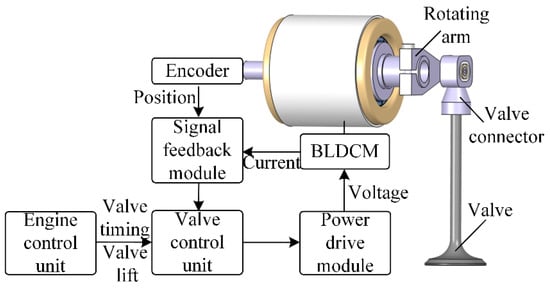
Figure 2.
Structure of the FVVA system.
The electronic variable valve system eliminates the traditional camshaft. The valve timing and valve lift can be adjusted flexibly according to the working conditions of the engine. In this system, the engine control unit controls the work of the engine. The valve control unit collects the valve timing and valve lift signals, and the signal feedback module feeds back the running state of the motor to the valve control unit; then, the valve control unit determines its output through the control algorithm. The power drive module amplifies the signal to control the velocity and position of the BLDCM. Through the control of the actuator, the control of valve operating parameters can be realized.
3. Structure Design
3.1. Requirement Analysis
Ideally, after receiving the control command, the actuator should drive the valve with the maximum current to uniformly accelerate and move at the maximum acceleration. When reaching the midpoint of the target position, the valve should be driven to uniformly decelerate with the maximum acceleration through the maximum reverse current. When the valve reaches the target position, the velocity is exactly 0, so that the valve movement can meet the requirements of a quick response and seating velocity at the same time. The maximum valve lift is required to be 8 mm, and the transition time is 4 ms. According to the law of kinematics, the acceleration that the valve should reach is 935 m/s2. Therefore, the maximum acceleration of the valve should be the design goal in the design.
Figure 2 shows the structure of the FVVA system. The BLDCM is connected to the valve through a crank-moving guide rod mechanism, which comprises a valve connector and a rotating arm. Through this mechanism, the rotary motion of the BLDCM can be converted into the linear motion of the valve. The length of the rotating arm has a great influence on the performance of the drive system. Determining the appropriate arm length provides maximum acceleration and ensures the quick response of the system. Assuming that the length of the boom is and the acceleration of the BLDCM is , the expression of the acceleration of the valve is:
Assuming the motor rotation angle is very small, the linear relationship between the valve displacement and motor rotation angle can be considered, and the relationship between motor torque and acceleration is:
where is the moment of inertia of the motor, is the mass of the valve, is the mass of the valve connector, and the rotating arm is made of an aluminum alloy structure. The moment of inertia is not considered during the design, and the angular acceleration of the motor rotor is:
By substituting Formula (4) into Formula (2), the valve acceleration can be obtained:
Taking the derivative of with respect to R results in:
By setting the derivative equal to zero, one finds the rotating arm length that provides maximum acceleration:
Substituting Formula (7) into Formula (5), the maximum valve acceleration is obtained as follows:
It can be seen from Formula (8) that the maximum acceleration of the valve movement is related to the maximum torque of the motor, the moment of inertia of the motor, and the quality of the valve and the valve connection. In order to ensure the linear relationship between the valve displacement and the motor rotation angle, the motor rotation angle is required to be limited to 20°, then the minimum arm length of the corresponding rotating arm is:
where is the maximum valve displacement and is the maximum angle of motor rotation, then the minimum moment of inertia requirement of the motor is:
Therefore, based on the above theoretical analysis, the steps to determine the structural parameters are as follows:
- According to Formula (10), the minimum moment of inertia of the motor is related to the maximum lift of the valve and the mass of the valve and the valve connector. The motor rotation angle is required to be limited to 20°.
- According to Formula (7), in order to ensure that the motor can provide the maximum acceleration of the valve, the arm length can be determined. In the design stage, the inertia of the rotating arm and the mass of the valve connector cannot be calculated, which can be temporarily ignored. It can be verified after the design is finished.
- According to Formula (8), the drive capacity of the motor is estimated through the motor parameters. It is necessary to ensure that the acceleration of the valve can meet the theoretical requirements.
- After determining the mechanism parameters, step 2 and step 3 are repeated, considering the moment of inertia of the rotating arm and the mass of the valve connector to ensure that the actuator meets the requirements.
3.2. Structure Design of the BLDCM
According to the previous section, two important standards for motor design are as follows:
- First, determine the minimum moment of inertia of the motor. In this system, the valve mass is 48 g, the maximum valve lift is 8 mm, and the rotation angle of the motor is limited to less than 20°. According to Formula (10), the minimum inertia of the motor is 2.54 × 10⁻⁵ kg·m2.
- After determining the arm length, according to Formula (8), the maximum acceleration of the valve is proportional to the maximum torque of the motor, and inversely proportional to the moment of inertia of the motor. It is necessary to ensure that the acceleration capability of the valve meets the theoretical requirements, namely a ≥ 935 m/s2.
In the motor design, the maximum torque of the motor is mainly related to factors, such as air gap flux density, current, and coil length. The thickness of different permanent magnets and the air gap will have a great impact on the air gap magnetic flux density. Under the constraints of external dimensions, the thicker the permanent magnet, the smaller the air gap size, and the greater the air gap flux density that can be achieved. However, as the thickness of the permanent magnets of the rotor increases, the rotor inertia will also increase, and the stator yoke will become more and more saturated. The reduction in the size of the air gap will inevitably lead to a reduction in the size of the coil, which will also lead to a drop in electromagnetic force. Therefore, it is necessary to find suitable structural parameters through optimized design to ensure that sufficient acceleration can be provided when the motor moment of inertia meets the requirements.
Maxwell can realize the parameterized analysis function, so the maximum acceleration that the valve can reach should be the optimization goal in the motor design. In the range of an outer diameter of 60 mm and length of 60 mm, with a permanent magnet size, stator and rotor inner and outer diameter, and motor length as variables, after a large number of variable parameter calculations, the final solution that can achieve the maximum acceleration is selected. Table 1 shows the basic parameters of the BLDCM. Figure 3 shows the 2-D flux density distribution of the BLDCM. At this time, the maximum torque that the motor can reach is 5.94 N∙m, the moment of inertia of the motor is 4.75 × 10⁻⁵ kg·m2, and the mass of the valve is 48 g. According to Formula (8), the maximum acceleration that can be reached is 1967 m/s2, which meets the design index of the motor.

Table 1.
Main parameters of the BLDCM.
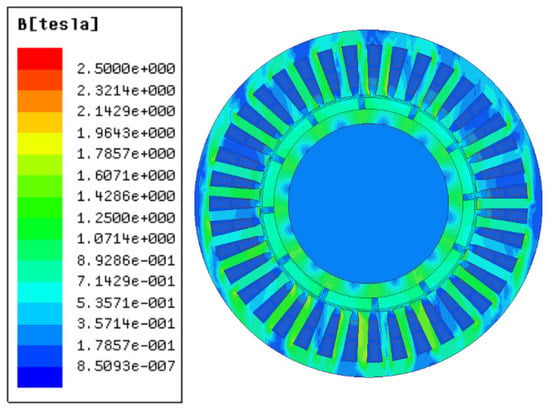
Figure 3.
2-D flux density distribution of the BLDCM.
3.3. Structure Design of the Crank-Moving Guide Rod Mechanism
Figure 4 shows the structure diagram of the crank-moving guide rod mechanism. The valve and the valve connector are connected by the valve holder and the valve lock clip. The valve holder and the valve connector are connected by threads, so that the valve lock clip and the valve groove form a relatively firm clamping-type fit. It can ensure that the valve connector can drive the valve to move quickly. Due to the relative sliding of the rotating arm and the valve connector, the rotating arm and the valve connector need to use materials with less friction to reduce wear and tear. At the same time, in order to reduce the quality, the method shown in Figure 4 is adopted. The material of the shaft sleeve is graphite copper, the material of the hole sleeve is titanium alloy, and the rotating arm and valve connecting parts are made of aluminum alloy with a relatively low density. As mentioned in the previous section, the motor parameters were determined, combined with Formula (7); when R = 31.5 mm, it can provide the maximum acceleration of the valve.
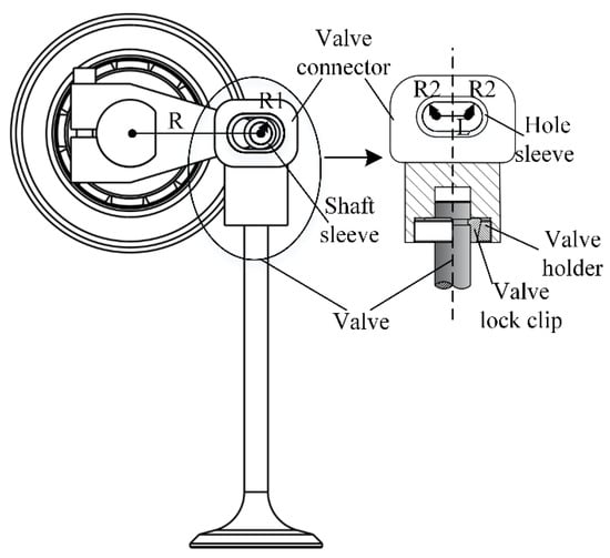
Figure 4.
The crank-moving guide rod mechanism.
3.4. Actuator Design Verification
Based on the analysis in the previous section, in order to increase the valve acceleration as much as possible, the motor rotating shaft adopts a hollow structure, and the end of the transmission shaft adopts a D-shaped structure for connecting with the crank moving guide rod mechanism. The valve position signal is collected by a 14-bit photoelectric encoder and connected to the motor drive shaft. Considering the moment of inertia of the arm sleeve and the mass of the valve connection, the total moment of inertia of the rotating part at this time is 6.8 × 10⁻⁵ kg·m2, and the mass of the moving part is 62.6 g. At this time, the initial boom arm length when the maximum acceleration of the valve can be provided is corrected to R = 33 mm. Compared with the initial design arm length change, it can ignore the inertia and mass changes caused by the arm length change. The structural parameters of the actuator at this time are shown in Table 2. According to Formula (8), the maximum acceleration that the valve can reach at this time is 1440 m/s2, and it meets the design requirements.

Table 2.
Main parameters of the actuator.
According to the above analysis and design, the development of the variable valve actuator based on BLDCM has been completed. The main components are shown in the Figure 5, where the valve and the valve lock clips used are existing products.
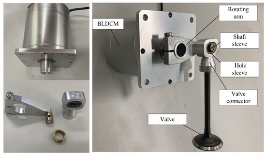
Figure 5.
The main components of the actuator.
4. Modeling and Analysis
4.1. Model for the FVVA System
The system is a mechanical-electrical coupling multi-physics system composed of the BLDCM, the crank-moving guide rod mechanism, and the valve. Therefore, mathematical models of the mechanical, electrical, and magnetic subsystems are established respectively when modeling [17].
In the mechanical subsystem, the mechanism can be simplified as shown in Figure 6. The forces received by the moving parts include the driving force Tmag, the mechanical damping force Fc, and the gas pressure F0 from the combustion chamber of the internal combustion engine. The mechanical damping force includes the air resistance during operation and the mechanical friction between the system mechanisms.
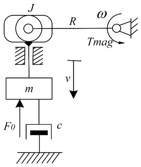
Figure 6.
Diagram of the dynamical model.
Since the swing angle of the motor is very small, it can be assumed that there is a linear relationship between the valve displacement and the swing angle of the motor. According to the dynamic model diagram, the differential equation of the motion process in the FVVA system has the following expression:
where the mechanical damping force is Fc = cv, the electromagnetic driving torque is Tmag. Since only valve motion control and seating performance control are considered in this article, the fully variable valve was not loaded into the engine to run. This article does not consider F0, so the valve force equation is:
where m is the total mass of the component moving with the valve, including the valve connector, the valve lock clamp, the valve holder, and the valve; J is the total moment of inertia of the rotating parts following the BLDCM, including the motor rotor, the rotating shaft, and the rotating arm; v is the velocity of the valve; and c is the mechanical damping coefficient.
In the circuit subsystem, the stator winding of the BLDCM is a three-phase Y-shaped connection, and it adopts a two-two conduction mode. To simplify the analysis, it can be assumed as follows [18]:
- The stator three-phase windings are symmetrical, and the stator current and the rotor magnetic field are symmetrically distributed.
- Excluding the influence of eddy current and hysteresis loss.
- Ignore the armature reaction and cogging effect of the motor.
- Ignore the power loss in the control circuit.
At this time, the three-phase winding of the motor is equivalent to a series circuit of resistance and inductance, and the motor balance equation is as follows:
Thus, the voltage equation of the three-phase winding is:
where is the phase winding inductance; is the resistance of the phase; is the mutual inductance; , , are phase currents; , , are phase voltages; and , , are back electromagnetic forces (EMFs). According to the voltage equation, the equivalent circuit is shown in Figure 7.
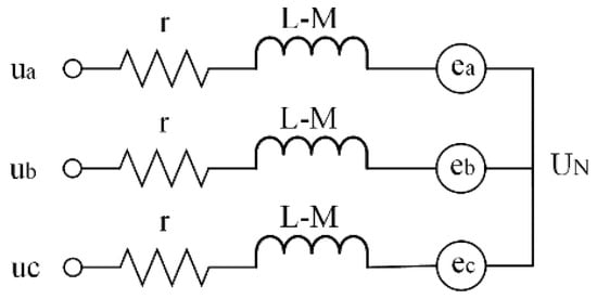
Figure 7.
Equivalent circuit diagram.
As the stator winding of the BLDCM is a three-phase Y-shaped connection, compared with phase voltage, line voltage is easier to measure. Therefore, line voltage model is adopted here, and the formula is as follows:
When the motor is running, only two phases of the stator winding are conducted. If the phase B and phase C are conducted, the resulting simplified model is shown in Figure 7. Therefore, the relationships between and is:
which also means that:
, so the line voltage becomes:
Therefore,
where is the DC bus voltage; is the line back EMF coefficient; and is the velocity of the motor.
In the magnetic circuit subsystem, the rotor of the BLDCM receives Loren magnetic force in the magnetic field. It is the main driving force of the valve. Regardless of the influence of the mechanical loss and stray loss of the rotor on the BLDCM, the electromagnetic torque expression of the BLDCM is as follows:
where is the electrical angular velocity of BLDCM, and when the motor is running, only two phases of the stator winding are conducted. Therefore, the electromagnetic torque expression of BLDCM can be simplified as:
where is the motor torque coefficient, and the motor torque constant depends on the size and material of the motor stator and rotor structure. The torque constant and the back-EMF constant can be obtained through the finite element analysis of the electromagnetic field.
Figure 8 shows the relationship between the systems. The voltage is applied to the BLDCM to generate current in the coil, and the electromagnetic force is applied to the rotor of the BLDCM in the magnetic field.
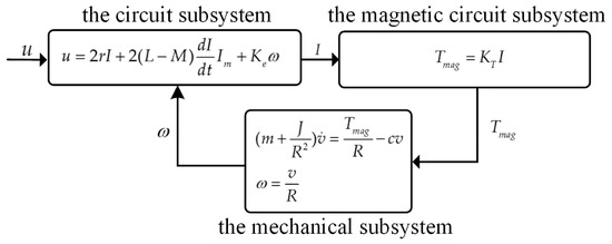
Figure 8.
Coupling of subsystems of the FVVA system.
4.2. Motion Control Algorithm of the FVVA System
In order to achieve precise controllability of the valve in operation, three closed-loop cascade control is used in this research, namely position loop, velocity loop, and current loop. The three are connected in cascade. The control block diagram is shown in Figure 9. The current loop serves as the regulator of current, the velocity loop as the regulator of velocity, and the position loop as the regulator of position. The PI control algorithm is adopted for all three loops, which has a low calculation time, simple algorithm, and good tracking performance. The tracking error signal is defined as:
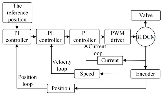
Figure 9.
Three-loop control system for the FVVA system.
The PI control law is as follows:
where , , , , and are the tracking error, reference value, feedback value, proportional, and integral gains of the controller, respectively.
In this model, the position loop receives the reference position and feedback position, and then outputs the reference velocity by calculating, likewise, the velocity loop to receive reference velocity and feedback velocity. It then outputs the reference current by calculating, the reference current determines the direction of motor rotation, and also determines the direction of the movement of the valve. The current loop receives the reference current and feedback current, and then outputs the specified duty ratio, to control the voltage of load on the motor.
The driving method of BLDCM is also one of the key steps of system design. This research uses the most commonly used full-bridge drive method for three-phase BLDCM as shown in Figure 10. It mainly consists of a three-phase inverter and an insulated-gate bipolar transistor (IGBT) driver. The effective control is made by using Pulse Width Modulated (PWM). According to the motor rotor position signal, the three-phase winding of the motor is controlled on and off. It adopts the two-by-two conduction mode, that is, according to the position signal, only two phases are turned on at the same time. The torque fluctuation of the motor is small in this case [19]. Table 3 shows the relationship between the BLDCM rotor position and the winding sequence. Through electronic commutation, it can generate a rotating magnetic field to drive the motor rotor to rotate. Here, 1 means the upper bridge arm is on, and 0 means the lower bridge arm is on.

Figure 10.
BLDCM control using PWM.

Table 3.
The relationship between winding sequence and position.
Figure 11 shows the Simulink model of the FVVA system based on Matlab. The model is divided into the three closed-loop control modules, the power drive and motor module, the crank-movement guide rod mechanism module, and valve motion modules. Among them, the output duty cycle is calculated through position, velocity, and current feedback in the three closed-loop control modules. Combined with the commutation command shown in Table 3, the specified PWM is output to the power drive and the motor module, thereby outputting the position, velocity, and current signals that need to be fed back. Then, it transmits the torque to the valve through the crank-movement guide rod mechanism, thereby drive valve movement. The precise position control of the valve is ensured by controlling the input of a given position signal.
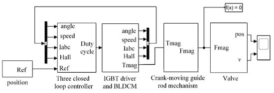
Figure 11.
MATLAB/Simulink model of the FVVA system.
4.3. Results and Discussion
The biggest feature of the FVVA system is that the valve operating parameters can be continuously adjusted in real time, including the variable valve timing, variable valve opening duration, and variable lift. Therefore, it is necessary to adjust the parameters of the valve movement process to verify the performance of the FVVA system.
In the FVVA system, the variable parameter adjustment of the valve can be achieved by adjusting the command to control the opening or closing of the valve. The parameters listed in Table 1 and Table 2 were used for the simulation research. Figure 12 shows the valve position curves of the engine under low, medium, and high loads. Among them, under low load conditions, the given valve lift is 4 mm, the valve opening duration is 8 ms, and the maximum position of the simulation result is 3.98 mm with an error of 0.02 mm. Under medium load conditions, the given valve lift is 8 mm, the valve opening duration is 8 ms, and the maximum position of the simulation result is 7.97 mm with an error of 0.03 mm. Under high load conditions, the given valve lift is 8 mm, the valve opening duration is 16 ms, and the maximum position of the simulation result is 7.95 mm with an error of 0.05 mm. It can be seen from the results that the FVVA system can realize variable valve timing, variable opening duration, and variable lift under different operating conditions.
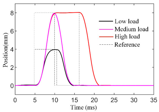
Figure 12.
Results of flexible valve motion control.
Figure 13 shows the valve movement position and velocity curve when the maximum valve lift is 8 mm and the valve opening duration is 16 ms under high load conditions. As shown in the figure, the valve movement transition time is about 3.8 ms, and the seating velocity is 0.18 m/s. It meets the design requirements.
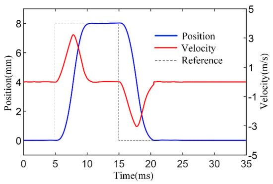
Figure 13.
Position and velocity curve when lift is 8 mm.
Table 4 compares the performance of the FVVA system with the traditional valve drive system and the EMCLV system. It can be seen that compared with the EMCLV system, the FVVA system has a larger seating speed. Even so, on the basis of realizing the variable valve timing of the EMCLV system, the FVVA system can also provide variable valve lift, which brings greater advantages to the internal combustion engine. The three closed loop PID control algorithm used in this paper is relatively simple and is difficult to be integrated into the internal combustion engine electronic control system. In the later stage, the algorithm can be optimized to achieve a lower seating speed and faster response time.

Table 4.
Comparison of performance of the three systems.
Finally, it should be pointed out that the exhaust valve cannot be fitted with this motor, because it does not have enough torque to support the combustion forces.
5. Conclusions
This article designed an FVVA system based on BLDCM. The overall design of the system was completed through the demand analysis of the system. The system is simple in structure and control. This design allows rapid recalibration of valves in situations where they are prone to wear and temperature changes, making the system more flexible than conventional valve actuators. The rotary motion of the BLDCM is converted into the linear motion of the valve by using a crank moving guide rod mechanism. It changes the valve lift by increasing or decreasing the BLDCM swing angle when the valve is opened, and it changes the transition time between valve opening or closing by increasing or decreasing the angular velocity of the BLDCM.
The simulation results show that the system can provide suitable valve opening and closing time or lift under different operating conditions of the engine. It meets the design requirements. Compared with the traditional camshaft mechanism, the FFVA system can provide a richer valve operation strategy when the engine is running. Depending on the working state of the engine, the valve can be opened and closed at different times with different lift.
Although the result of the simulation shows that the design can meet the design requirements very well, as said earlier, the motor cannot provide enough torque to support the combustion forces for the exhaust valve, and the installation of the motor is also an important issue to consider. There are inevitable disturbances when the valves work, so we need to optimize the algorithm and structure to get a better variable valve system. The next step in the research is to redesign a smaller BLDCM to fit their mounting sizes, and then test the drive system in an actual internal combustion engine to verify its feasibility. This will provide a better understanding of the disturbances that occur during engine operation.
Author Contributions
Supervision, L.L. and Z.X.; Research—original draft—editing, L.J.; Technical support, X.P. All authors have read and agreed to the published version of the manuscript.
Funding
This work was supported by the National Natural Science Foundation of China (Grant No. 51975297 and No. 51875290).
Conflicts of Interest
The authors declare no conflict of interest.
Abbreviations
| FVVA | fully variable valve actuation |
| BLDCM | brushless direct current motor |
| EMCL | electromechanical camless valve |
| PWM | pulse width modulated |
| the maximum velocity of the engine | |
| The maximum time allowed for valve opening or closing | |
| the maximum continuous crank angle | |
| the length of the boom | |
| the acceleration of the BLDCM | |
| the acceleration of the valve | |
| the moment of inertia of the motor | |
| the mass of the valve | |
| the mass of the valve connector | |
| the maximum valve displacement | |
| the maximum angle of motor rotation | |
| Tmag | the electromagnetic driving torque |
| c | the mechanical damping coefficient |
| F0 | the combustion forces |
| v | the velocity of the valve |
| phase winding inductance | |
| resistance of the phase | |
| mutual inductance | |
| A phase current | |
| B phase current | |
| C phase current | |
| A phase voltage | |
| B phase voltage | |
| C phase voltage | |
| EMF | back ElectroMagnetic Forces |
| the EMF generated in A phase | |
| the EMF generated in B phase | |
| the EMF generated in C phase | |
| the electrical angular velocity of BLDCM | |
| the tracking error | |
| the reference value | |
| the feedback value | |
| proportional gains of the controller | |
| integral gains of the controller |
References
- Ortlieb, P.; Derichs, S.; Perge, J. Analytical study on the influence of valve pumping work on engine efficiency. Automotive and Engine Technology. Int. J. Automot. Mech. Eng. 2020, 5, 37–44. [Google Scholar]
- Pournazeri, M.; Khajepour, A.; Huang, Y. Development of a new fully flexible hydraulic variable valve actuation system for engines using rotary spool valves. Mechatronics 2017, 1–20. [Google Scholar] [CrossRef]
- Bota, J.; Kumagai, T.; Kuboyama, T.; Hatamura, K. Development of Continuously Variable Phase and Lift/Duration Mechanism for Widely Available Automobile Engines. SAE Int. J. Engines 2013, 6, 327–335. [Google Scholar] [CrossRef]
- Hattori, M.; Inoue, T.; Mashiki, Z.; Takenaka, A.; Urushihata, H.; Morino, S.; Inohara, T. Development of Variable Valve Timing System Controlled by Electric Motor. SAE Int. J. Engines 2008, 1, 985–990. [Google Scholar] [CrossRef][Green Version]
- Kreuter, P.; Heuser, P.; Reinicke-Murmann, J.; Erz, R.; Peter, U.; Böcker, O. Variable Valve Actuation—Switchable and Continuously Variable Valve Lifts. SAE Tech. Pap. Ser. 2003, 112, 112–123. [Google Scholar] [CrossRef]
- Liu, L.; Chang, S. Motion control of an electromagnetic valve actuator based on the inverse system method. Proc. Inst. Mech. Eng. Part D J. Automob. Eng. 2012, 226, 85–93. [Google Scholar] [CrossRef]
- Shiao, Y.; Dat, L. A new electromagnetic valve train with PM/EM actuator in SI engines. Trans. Can. Soc. Mech. Eng. 2013, 37, 787–796. [Google Scholar] [CrossRef]
- Kim, J.; Dennis, K. A new electromagnetic engine valve actuator with less energy consumption for variable valve timing. J. Mech. Sci. Technol. 2007, 21, 602–606. [Google Scholar] [CrossRef]
- Li, Y.; Khajepour, A.; Liu, K. Power and fuel economy optimizations of gasoline engines using hydraulic variable valve actuation system. Appl. Energy 2017, 206, 577–593. [Google Scholar] [CrossRef]
- Li, Y.; Khajepour, A.; Devaud, C. Realization of variable Otto-Atkinson cycle using variable timing hydraulic actuated valve train for performance and efficiency improvements in unthrottled gasoline engines. Appl. Energy 2018, 222, 199–215. [Google Scholar] [CrossRef]
- Sun, Z.; Kuo, T.W. Transient Control of Electro-Hydraulic Fully Flexible Engine Valve Actuation System. IEEE Trans. Control. Syst. Technol. 2009, 18, 613–621. [Google Scholar] [CrossRef]
- Ma, J.; Zhu, G.A. Hartsig, Model-based predictive control of an electro-pneumatic exhaust valve for internal combustion engines. Am. Control. Conf. 2008, 11, 298–305. [Google Scholar] [CrossRef]
- Gerlach, A.; Fritsch, M.; Benecke, S.; Rottengruber, H.; Leidhold, R. Variable Valve Timing With Only One Camshaft Actuator for a Single-Cylinder Engine. IEEE/ASME Trans. Mechatron. 2019, 24, 1839–1850. [Google Scholar] [CrossRef]
- Parlikar, T.; Chang, W.; Qiu, Y.; Seeman, M.; Perreault, D.J.; Kassakian, J.G.; Keim, T.A. Design and experimental implementation of an electromagnetic engine valve drive. IEEE/ASME Trans. Mechatron. 2005, 10, 482–494. [Google Scholar] [CrossRef]
- Heinzen, A.; Gillella, P.; Sun, Z. Iterative learning control of a fully flexible valve actuation system for non-throttled engine load control. Control. Eng. Pract. 2011, 19, 1490–1505. [Google Scholar] [CrossRef][Green Version]
- Dimitrova, Z.; Tari, M.; Lanusse, P.; Aioun, F.; Moreau, X. Development and Control of a Camless Engine Valvetrain. IFAC-PapersOnLine 2019, 52, 399–404. [Google Scholar] [CrossRef]
- Vaiana, N.; Sessa, S.; Marmo, F.; Rosati, L. Nonlinear dynamic analysis of hysteretic mechanical systems by combining a novel rate-independent model and an explicit time integration method. Nonlinear Dyn. 2019, 98, 2879–2901. [Google Scholar] [CrossRef]
- Lee, D. Wide-range Speed Control Scheme of BLDCM Based on the Hall Sensor Signal. J. Power Electron. 2018, 18, 714–722. [Google Scholar]
- Sumega, M.; Varecha, P.; Rafajdus, P. Sources of torque ripple and their influence in BLDCM drives. J. Transp. Res. Procedia 2019, 40, 519–526. [Google Scholar] [CrossRef]
- Chladny, R.R.; Koch, C.R. Flatness-based tracking of an electrome-chanical variable valve timing actuator with disturbance observer feedforward compensation. IEEE Trans. Control Syst. Technol. 2008, 16, 652–663. [Google Scholar] [CrossRef]
Publisher’s Note: MDPI stays neutral with regard to jurisdictional claims in published maps and institutional affiliations. |
© 2020 by the authors. Licensee MDPI, Basel, Switzerland. This article is an open access article distributed under the terms and conditions of the Creative Commons Attribution (CC BY) license (http://creativecommons.org/licenses/by/4.0/).