Abstract
Vacuum circuit breakers are increasingly used as switching apparatus in electric power systems. The vacuum circuit breakers (VCBs) have very good operating properties. VCBs are characterized by specific physical phenomena that affect overvoltage exposure of the insulation systems of other devices. The most important phenomena are the ability to chop the current before the natural zero crossing, the ability to switch off high-frequency currents, and the rapid increase in dielectric strength recovery. One of the devices connected directly to vacuum circuit breakers is the distribution transformer. Overvoltages generated in electrical systems during switching off the transformers are a source of internal overvoltages in the windings. The analysis of the exposure of transformers operating in electrical networks equipped with vacuum circuit breakers is of great importance because of the impact on the insulation systems of switching overvoltages (SO). These types of overvoltages can be characterized by high maximum values and atypical waveforms, depending on the phenomena in the circuit breaker chambers, system configuration, parameters of electrical devices, and overvoltage protection. Overvoltages that stress the internal insulation systems are the result of the windings response to overvoltages at transformer terminals. This article presents an analysis of overvoltages that stress the transformer insulation systems, which occur while switching off transformers in systems with vacuum circuit breakers. The analysis was based on the results of laboratory measurements of switching overvoltages at transformer terminals and inside the winding, in a model medium-voltage electrical network with a vacuum circuit breaker.
1. Introduction
The basic task of distribution companies is to ensure the reliability of electrical power delivery to the customers. The reliability of transformers has a great influence on uninterrupted power system operations. The use of a transformer design ensuring the appropriate electrical strength of transformer insulation systems, resulting from the expected exposures, is of fundamental importance for meeting the above requirement. On the other hand, economic and technical conditions make it necessary to reduce the safety factor of a device’s electrical strength. Hence, it is necessary to optimize the technical solutions of transformers. This requires a detailed analysis of transformer operational stress, among which overvoltage stress is the most important. Under operating conditions, transformers are subjected to transients with various waveforms and maximum values. Currently, due to the use of many devices in power systems with parameters different from those used so far (e.g., vacuum circuit breakers), insulation systems for power devices are exposed to the effects of surges not occurring thus far. The broad use of vacuum circuit breakers, especially in medium-voltage networks, results from very good operating properties. Vacuum circuit breakers have specific physical properties that influence overvoltage exposures of insulation systems of fed objects. The most important phenomena are the ability to chop the current before the natural zero crossing, the ability to switch off high-frequency currents, and the rapid increase in the electric recovery strength [1,2,3].
The waveforms and maximum values of switching overvoltages that stress the insulation systems of transformers in electrical networks with vacuum circuit breakers depend on the phenomena occurring in the switch chambers, configuration of electrical systems and parameters of electrical devices, the reaction of transformers to overvoltages in power systems, and overvoltage protection.
The results of these phenomena in networks with vacuum circuit breakers are switching overvoltages with large maximum values and atypical waveforms reaching the transformer terminals. These transients are a source of overvoltages in the windings that are exposed in the internal insulation systems of transformers [1,2,3,4].
Power transformers are protected against overvoltages mainly by the application of metal oxide surge arresters. However, this method has not completely solved the problems related to overvoltage protection. Many transformers have been damaged as a result of overvoltage stress, despite the fact that the transformers passed the normalized voltage tests with a positive result and were protected against overvoltages with the use of surge arresters [5,6,7,8,9,10].
The maximum values of residual voltages of the surge arresters are about three times higher than the rated voltages of the protected transformers. Overvoltages with maximum values lower than the protection level of the arresters, arising mainly during switching operations and earth faults, reach transformers without changing the maximum values and waveforms [11,12].
The continuous increase in demand for electricity, requirements for power supply reliability, and technical limitations of design solutions of transformer insulation systems imply that the analysis of overvoltages which expose transformer insulation systems is of great practical importance. Research work on overvoltage exposures of power transformers has been carried out in many research centers [13,14,15,16]. The issues of transformer overvoltage exposures are also the content of the works carried out as part of the A2/C4.39 CIGRE Working Group, established in 2008, which covers the problems of interactions between power transformers and power systems [13]. Recent work from the task force of the IEEE Power & Energy Society Transformers Committee investigated the interaction of power equipment in High Voltage (HV) and Extra High Voltage (EHV) stations [14].
Particularly important is the analysis of a transformer system’s exposure to overvoltages with nonstandard waveforms generated when switching transformers with vacuum circuit breakers. It is particularly important to identify the exposure of the insulation systems of internal transformer windings to overvoltages with atypical waveforms generated in systems with vacuum circuit breakers [17,18,19,20,21]. Internal overvoltages in transformers depend on the waveforms from external transient voltages and transient phenomena inside the windings. Windings can be assumed as complex RLC electromagnetic systems with parameters depending on design solutions, properties of current path materials, insulation systems, and magnetic circuits of transformers [22,23,24,25,26,27].
The group of problems included in this article contains an analysis of the exposure of transformer insulation systems during switching operations in electrical systems with vacuum circuit breakers. The analysis is based on the results of laboratory tests of switching overvoltages in transformers, protected by metal oxide surge arresters, operating in systems with vacuum circuit breakers, modeling part of a typical medium-voltage network. This research covers vacuum circuit breaker (VCB) switching overvoltages at transformer terminals in model medium-voltage networks of various configurations and overvoltages inside transformer windings. The test results show the switching overvoltage waveforms at transformer terminals and overvoltages inside the windings.
2. Transient Phenomena during Switching Transformers with Vacuum Circuit Breakers
The waveforms and maximum values of overvoltages generated when switching off electrical devices with vacuum circuit breakers mainly depend on the chopped current value before the natural zero crossing. Chopping the current in the vacuum circuit breakers chambers is a consequence of the rapid extinguishing of the electric arc in the unstable burning phase. At small instantaneous values of the arcing current, a high-frequency oscillating current appears, flowing in the W-Lk-Rk-C0-Cz-Lz circuit (Figure 1), and is superimposed on the fundamental component of the main frequency current. The high-frequency current can balance the main frequency current of the circuit being shut down and cause the instantaneous value of the circuit to suddenly drop to close to zero. In such conditions, the circuit is switched off at a non-zero value of the fundamental current (cut-off current) flowing through the load inductance L0 (virtual current chopping) [17,18].
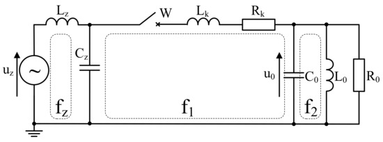
Figure 1.
Equivalent scheme of a system phase with a transformer connected with a vacuum circuit breaker, where uz—source voltage; Lz, Cz—inductance and capacitance of the source circuit; fz—natural frequency of the source circuit; W—vacuum circuit breaker; Lk, Rk—inductance and resistance of cable line; f1—natural frequency of the cable line circuit; C0, L0, R0—equivalent parameters of capacitance, inductance, and resistance of the test object; f2—natural frequency of tested windings.
Due to the very fast recovery of the electrical strength between contact gap, arc re-ignitions are usually not present in vacuum switches. However, if they do occur, they increase switching overvoltages. The overvoltage values in such cases may significantly exceed the voltage values resulting from the energy stored in the switched-off device at the time of the current chopping.
Figure 2 shows the voltage waveforms in the circuit being switched off (Figure 1) during re-ignition of the arc in the W switch in comparison to the switch current waveforms [18,19,20]. After cutting the current in the circuit breaker, the current in the inductance L0 continues to flow through the capacitance C0, causing a rapid change in the voltage u0 at its terminals. At the same time, the recovery voltage between the contacts of the circuit breaker increases, which is the difference between the supply side voltage uZ and the u0 ≈ uC load side voltage of VCB. With a slow rate of increase in the strength of the gap between the UWp contacts and a rapid increase in the recovery voltage (u0 ≈ uC), restrikes of the arc may occur. This is accompanied by the flow of high-frequency current in the Cz-W-L0-C0 circuit (Figure 1) and a very quick recharge of the capacitance C0 to a higher voltage uC(j), if the high-frequency current is switched off at the first zero crossing. Within a short time of burning the arc Thf/2, the value of the current in the inductance of the switched-off transformer Lo will not change.
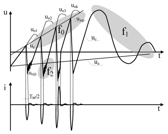
Figure 2.
Characteristic waveforms of the network voltage uz, voltage uc on the switched-off transformer, and the recovery dielectric strength of the circuit breaker uwp as well as the waveform of the current and the vacuum circuit breaker [15,16].
When the voltage uC(j) at capacitance C0 after the arc is extinguished is greater than voltage uC(i) at the instance of arc ignition, the energy stored in elements L0 and C0 increases. As a consequence of this, the maximum values of the voltage expected at the terminals of the disconnected circuit also increase.
3. Characteristics of the Laboratory Stand
Overvoltage tests were carried out in a setup that was part of a medium-voltage network, shown in Figure 3. The analysis focused on the overvoltages that affected the internal insulation of the medium-voltage transformer, in a system with a vacuum circuit breaker, when the transformer was switched off.
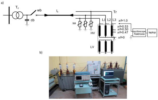
Figure 3.
System for testing overvoltages when switching off the transformer with a vacuum circuit breaker: (a)—test system diagram; (b)—stand view: wb—vacuum switch, Tz—power transformer, Tr—switched off transformer, lc—85 m or 2 m long cable line, sa—surge arresters, cb—capacitor bank 60 nF [15,16].
The system includes a supply transformer Tz and a switched-off transformer Tr, a vacuum circuit breaker wb type VD4, and a power cable line lc. The supply transformer was directly connected to the Low Voltage (LV) network. This connection allows to produce the HV at the primary side of the transformer. The VD4 circuit breaker was manually controlled to switching the load circuit on and off. The test transformer Tr was in a no-load state at the secondary side. The high-voltage TESTEC HVP-15HF probes connected to a Tektronix digital oscilloscope TDS 784D and a computer were used to measure the voltage waveforms in the system during switching operations.
The frequency characteristics of impedance were obtained in the SFRA (Sweep Frequency Response Analysis) measurement stand. This stand was equipped with programmable waveform generator Tektronix AFG310 and Tektronix TDS1012 oscilloscope. The control algorithms were implemented in the LabView software. The stand used a maximum 20 Vpp supply voltage to determine the desired frequency characteristics. The response of the object was measured at the non-inductive 50 ohm resistor, and the frequency characteristics were obtained in the 10 Hz to 2 MHz range with 200 steps distributed logarithmically [26].
The basic electrical parameters of the transformers and the circuit breaker are presented in Table 1 and Table 2. The line lc is made with the cable type RG–213U MIL.C 17/D (Table 3) with a length of 85 m or 2 m. The transformer was protected against overvoltages by the POLIM-D metal oxide surge arresters Table 4 [11,12,28].

Table 1.
Rated parameters of Tz and Tr transformers (Figure 3).
Table 2.
Rated parameters of vacuum circuit breaker type VD4 (Figure 3).
Table 3.
Parameters of the RG– 213U MIL.C 17/D cable of the lc line (Figure 3) [29].
Table 4.
Parameters of the POLIM-D8N surge arrester used in the test setup [28].
Overvoltage tests were performed in single-phase and three-phase systems. The results of the tests in the single-phase system were the basis for the analysis of the influence of the electrical system configuration on the waveforms of switching overvoltages. In a single-phase system, there is no influence of voltages and currents in adjacent phases on the waveforms of the measured switching overvoltages. The purpose of the tests in a three-phase system was to analyze the influence of the configuration of the electrical system and metal oxide surge arresters on the waveforms and maximum values of overvoltages that are exposed to the insulation system of the medium-voltage transformer when switched off with a vacuum circuit breaker. The impedance frequency characteristics were obtained in the single-phase system with 20 Vpp source voltage. For the analyzed frequency range and natural frequencies of the transformer, the test object was treated as a linear time invariant class, and for the silicon steel the cut-off frequency was assumed at the level of 1 kHz. The scope of the measurement was as follows:
- measurement of voltage waveforms at the transformer terminals in the 3-phase system during switching of VCB;
- analysis of the impact of cable line connecting the VCB to the transformer on the overvoltage level and waveform shapes;
- determination of natural frequencies appearing in the measured voltage waveforms during VCB switching;
- measurement of impedance frequency characteristics of the test system seen from the source transformer terminals, and determination of the resonant frequencies of the system for different cable lengths;
- measurement of voltage waveforms at selected points inside the tested transformer winding during VCB operation.
4. Tests of Switching Overvoltages on Terminals of the Transformer
The tests of switching overvoltages in transformers included the acquisition of phase voltage waveforms when switching off the transformer in electrical systems of various configurations. The systems consisted of a cable line lc connected between the vacuum circuit breaker wb and the transformer Tr, and a second cable line lc of various lengths (85 m and 2 m) connected between the circuit breaker and the supply transformer Tz. The aim of the research was a comparative analysis of switching overvoltages occurring during switching off transformers in systems with various configurations and an analysis of the influence of surge arresters on the shapes of switching overvoltages in systems with vacuum circuit breakers. The research included the measurements of overvoltage waveforms in systems with and without surge arresters (Figure 4 and Figure 5).
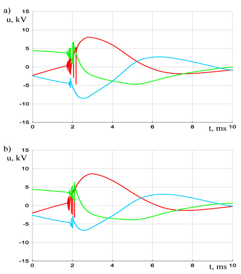
Figure 4.
Transient overvoltage waveforms at transformer terminals Tr (Figure 3) switched off with a vacuum circuit breaker wb connected to the transformer by a 85 m long cable line lc: (a)—system with surge arresters, (b)—system without surge arresters.
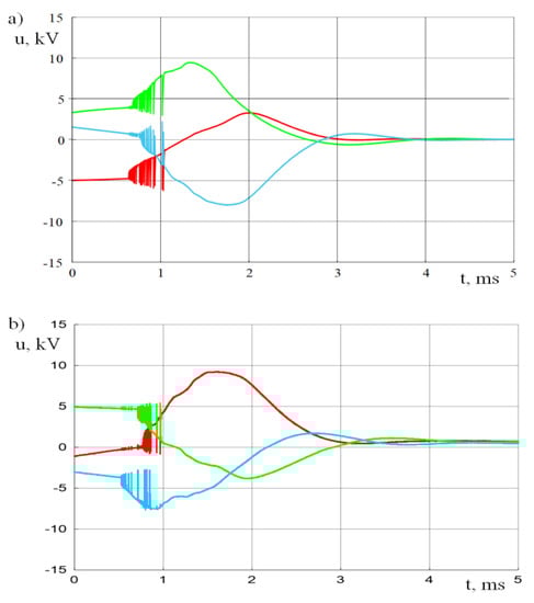
Figure 5.
Transient overvoltage waveforms at transformer terminals Tr (Figure 3) switched off with a vacuum circuit breaker wb connected to the transformer by a 2 m long cable line lc: (a)—system with surge arresters, (b)—system without surge arresters.
Based on the analysis of the overvoltage measurement results presented in Figure 4a and Figure 5a selected for one phase L3 (Figure 3), the frequencies f0, f1, and f2 (Figure 2) were determined for the components of the overvoltage waveforms at the transformer terminals switched off with a vacuum circuit breaker. The waveforms of overvoltages on the HV terminals of the transformer Tr for the selected L3 phase, determined in the system (Figure 3) in which the cable line lc was 85 m, are shown in Figure 6, and for the system in which the lc line is 2 m length in Figure 7.
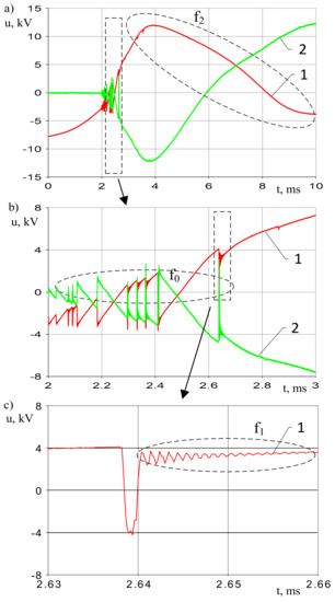
Figure 6.
Transient phase voltage waveforms at the transformer terminals Tr, switched off with a vacuum circuit breaker W, connected to the transformer by a 85 m long cable line lc in a single-phase system and voltage between the contacts of the circuit breaker wb (Figure 3): (a)—voltage waveforms in 10 ms time window; (b,c)—parts of the diagram from Figure 6a: 1—phase voltage across the transformer Tr, 2—voltage between the contacts of the vacuum circuit-breaker wb.
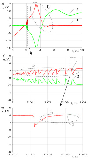
Figure 7.
Transient phase voltage waveforms at transformer terminals Tr, switched off with a vacuum circuit breaker wb, connected to the transformer by 2 m long line lc in a single-phase system and voltage between the circuit breaker contacts wb (Figure 3): (a)—voltage waveforms in 10 ms time window; (b,c)—fragments of the diagram in Figure 7a: 1—phase voltage across the transformer Tr, 2—voltage between the contacts of the vacuum circuit-breaker wb.
The frequencies determined in this way were compared with the natural frequencies of the system (winding under test-cable line-source transformer) determined on the basis of the results of measuring the impedance characteristics Z = g (f) presented in Figure 8 (Table 5). The impedance was measured from the source transformer terminals.
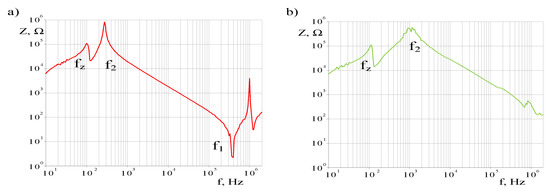
Figure 8.
Relations Z = g (f) of a single-phase experimental system with a vacuum circuit breaker wb (Figure 3): (a)—system: vacuum circuit breaker wb connected to the transformer with 85 m long cable line lc, (b)—system: vacuum circuit breaker wb connected to the transformer with 2 m long cable line lc.
Table 5.
The frequencies f0, f1, and f2 (Figure 2) of oscillating components of overvoltage waveforms at the terminals of a transformer switched off with a vacuum circuit breaker determined on the basis of impedance characteristics measurements.
The analysis of the test results presented in Figure 6 and Figure 7 shows that the transformer insulation system was exposed to overvoltages with values much higher than the maximum operating voltage (Table 1). The wave shape depends on the configuration of the electrical system with a vacuum circuit breaker. Overvoltages consist of oscillating components, resulting from the restrikes between the contacts of the vacuum circuit breaker that is being opened. The overvoltage coefficient in the system with an 85 m long cable line connected between the vacuum circuit breaker, wb, and the transformer which is switched off, Tr, was 1.6, and the value of the overvoltage coefficient in a system in which the vacuum circuit breaker was connected to the transformer by 2 m long cable, line lc, was approximately 2. The investigation confirms that the metal oxide surge arresters (Table 5), with parameters in line with the standard recommendations for insulation coordination in power systems, do not have a significant impact on the overvoltage waveforms and do not damp oscillating components if the maximum values are lower than the protection level of the arresters. In the analyzed case, the residual voltage of the surge arrester was 4.76 p.u. Lack of surge arrester impact on the overvoltage waveform is justified by the construction of the surge arrester, which includes only passive elements, such as a nonlinear resistor, that do not impact the steepness of the surge.
The conducted tests, the results of which are presented in Figure 6, Figure 7 and Figure 8 and Table 5, show that the configuration of electrical systems had an influence on the transient voltage waveforms when transformers were switched off with vacuum circuit breakers. The frequencies of the transient voltage waveform components when the transformer was switched off also depend on the configuration of the electrical systems. The analysis of the results presented in Table 5 shows that shortening the cable line connecting the VCB to switched transformer increased the observed frequencies f0, f1, and f2. This fact is related with the reduction in electromagnetic wave travel time between VCB and Tr transformer and reduction in equivalent capacitance of the cable line. The resonant frequencies determined from the waveforms u = f (t) were close to the resonant frequencies determined on the basis of measured frequency characteristics Z = g (f). The observed differences result from different source transformer operating conditions during the measurements of overvoltage waveforms and during determination of the impedance frequency characteristics.
5. Investigation of the Distribution of Overvoltages in the Windings of a Transformer Which Is Switched off with a Vacuum Circuit Breaker
The tests consisted of measuring the overvoltage waveforms at the line terminals (x/l = 1.0) of the HV winding of the L3 phase of the transformer Tr, which was switched off with a vacuum circuit breaker wb (Figure 3), and in the middle part of the winding (point with the coordinate x/l = 0.5), and at points with the coordinates x/l = 0.53 and x/l = 0.47. The switched-off transformer was protected against overvoltages with the POLIM–D8N surge arresters.
The overvoltage waveforms inside the L3 phase winding of the transformer Tr switched off with a vacuum circuit breaker, recorded in the system (Figure 3) in which the cable line lc was 85 m long, is shown in Figure 9, and results determined in the system with the 2 m lc line are shown in Figure 10.
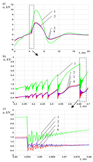
Figure 9.
Overvoltage waveforms inside the L3 phase winding when switching off the transformer Tr, protected by surge arresters with a vacuum circuit breaker connected to the transformer with an 85 m long cable line (Figure 3): (a) full scale, (b,c) different zooms of figure a), 1—phase voltage waveform on the winding line terminal (x/l = 1.0), 2—voltage waveform in the middle of the winding (x/l = 0.5), 3—waveform of the overvoltage in the point with the coordinate x/l = 0.53, 4—waveform of the overvoltage in the point with the coordinate x/l = 0.47.
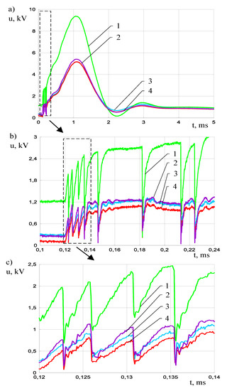
Figure 10.
Overvoltage waveforms inside the L3 phase winding when switching off a Tr transformer protected by surge arresters with a vacuum circuit-breaker connected to the transformer by a 2 m long cable line (Figure 3): (a) full scale, (b,c) different zooms of figure a), 1—phase voltage waveform on the winding line terminal (x/l = 1.0), 2—voltage waveform in the middle of the winding (x/l = 0.5), 3—waveform of the overvoltage in the point with the coordinate x/l = 0.53, 4—waveform of the overvoltage in the point with the coordinate x/l = 0.47.
Transient voltages at the line terminals of the transformer winding, which was switched with a vacuum circuit breaker, were in the form of waveforms resulting from a sequence of restrikes in the contact chambers of the vacuum circuit breaker and from the configuration of the electrical system and parameters of electrical devices. The frequency of the oscillating components of the transient voltage inside the windings depends mainly on the transient phenomena occurring in the electrical system, which are significantly influenced by the length of the line lc connecting the switched-off transformer Tr with the vacuum circuit-breaker wb. Overvoltages appearing on the line terminals, despite the applied metal oxide surge arresters, propagated inside the winding. Overvoltage waveforms were not damped inside the winding. Internal overvoltages oscillated. Their waveforms, like the surge waveforms at the transformer input terminals, contained oscillatory components of various frequencies. Such waveforms may stimulate overvoltages with large maximum values inside the windings if the overvoltage frequency is equal to the transformer’s natural frequency. The consequence of this may be a non-linear distribution of switching voltages and a significant increase in the exposure of insulation systems inside the windings.
6. Conclusions
Based on the test results, it can be concluded that when switching off transformers with vacuum circuit breakers, there is an increase in the exposure of the insulating systems of the internal windings to overvoltages, with atypical waveforms occurring at the input terminals of the windings. The maximum values of overvoltages occurring when switching off transformers depend on the phenomena occurring inside the contact chambers as well as in electrical systems and windings.
Surge arresters made of metal oxides reduce the maximum values of switching overvoltages with values higher than the protection level of the surge arresters, but they do not have a significant impact on the oscillatory components of the overvoltages and do not reduce the steepness of overvoltages.
The waveforms of overvoltages generated when switching off transformers with vacuum circuit breakers contain oscillatory transient components, with frequencies depending on the parameters of the devices and the configuration of electrical systems. Overvoltages occurring when switching off transformers with a vacuum circuit-breaker contain oscillatory components resulting from multiple strikes in the circuit breaker chambers and transient phenomena in electrical systems, which are significantly influenced by the length of the line connecting the transformer with the circuit breaker. The waveforms of internal overvoltages that compromise the insulation systems of windings cooperating with vacuum circuit breakers are the same as the waveforms of overvoltages on the input terminals of transformers.
The overvoltage waveforms are not damped inside the winding. Internal overvoltages are oscillating. Their waveforms, like the surge waveforms at the transformer input terminals, contain oscillatory components of various frequencies. Overvoltages with such waveforms may constitute sources of overvoltages with large maximum values inside the windings if the overvoltage frequency is consistent with the transformer’s natural frequency. The consequence of this may be a non-linear distribution of switching voltages and a significant increase in the exposure of insulation systems inside the windings.
Author Contributions
Conceptualization, M.F. and J.F.; methodology, M.K. and P.P.; validation, M.F., J.F., M.K. and P.P.; investigation, M.F., J.F., M.K. and P.P.; writing—original draft preparation, J.F., M.K.; writing—review and editing, M.F., and P.P.; All authors have read and agreed to the published version of the manuscript.
Funding
This research received no external funding.
Conflicts of Interest
The authors declare no conflict of interest.
References
- Theocharis, A.; Popov, M.; Seibold, R.; Voss, S.; Eiselt, M. Analysis of switching effects of vacuum circuit breaker on dry-type foil-winding transformers validated by experiments. IEEE Trans. Power Deliv. 2015, 30, 351–359. [Google Scholar] [CrossRef]
- Szewczyk, M.; Kuczek, T.; Oramus, P.; Piasecki, W. Modeling of Repetitive Ignitions in Switching Devices: Case Studies on Vacuum Circuit Breaker and GIS disconnector, Lecture Notes in Electrical Engineering. In Analysis and Simulation of Electrical and Computer Systems; Springer: Cham, Switzerland, 2015; Volume 324. [Google Scholar]
- Gustavsen, B. Study of transformer resonant overvoltages caused by cable-transformer high–frequency interaction. IEEE Trans. Pow. Deliv. 2010, 25, 770–779. [Google Scholar] [CrossRef]
- Lopez-Fernandez, X.M.; Álvarez-Mariño, C. Induced Transient Voltage Performance Between Transformers and VCB. Severity Factors and Case Studies. IEEE Trans. Pow. Deliv. 2015, 30, 1137–1144. [Google Scholar] [CrossRef]
- Hori, M.; Nishioka, M.; Ikeda, Y.; Naguchi, K.; Kajimura, K.; Motoyama, H.; Kawamura, T. Internal winding failure due to resonance overvoltages in distribution transformer caused by winter lightning. IEEE Trans. Pow. Deliv. 2006, 21, 1600–1606. [Google Scholar] [CrossRef]
- Lapworth, J.A.; Wilson, A. Transformer internal overvoltages caused by remote energisation. In Proceedings of the 2007 IEEE Power Engineering Society Conference and Exposition in Africa-Power Africa, Johannesburg, South Africa, 16–20 July 2007; pp. 1–6. [Google Scholar]
- Morched, A.S.; Marti, L.; Brierly, R.H.; Lackey, J.G. Analysis of internal winding stresses in EHV generator set–up transformer failures. IEEE Trans. Pow. Deliv. 1996, 11, 888–894. [Google Scholar] [CrossRef]
- Filipović-Grčić, B.; Jurisic, B.; Keitoue, S.; Župan, A. Analysis of Overvoltages on Power Transformer Recorded by Transient Overvoltage Monitoring System. In Proceedings of the 5th International Colloquium Transformer Research and Asset Management, Opatija, Croatia, 9–12 October 2019. [Google Scholar]
- Schei, A.; Alstad, K.; Sund, J.B.; Rian, W. Resonant overvoltages in power station transformers initiated by switching transients in the connected cable network. CIGRE Sess. 1984, 7–12. Available online: http://e-cigre.org/ (accessed on 14 October 2020).
- Lindell, E.; Liljestrand, L. Effect of Different Types of Overvoltage Protective Devices Against Vacuum Circuit-Breaker-Induced Transients in Cable Systems. IEEE Trans. Pow. Deliv. 2016, 31, 1571–1579. [Google Scholar] [CrossRef]
- IEC 60071-1:2019. Insulation Co-ordination—Part 1: Definitions, Principles and Rules. Available online: https://webstore.iec.ch/publication/65606 (accessed on 12 October 2020).
- IEC 60099-5: 2018. Surge Arresters—Part 5: Selection and Application Recommendations. Available online: https://webstore.iec.ch/publication/736 (accessed on 12 October 2020).
- Joint Working Group A2/C4.39-CIGRE. Electrical Transient Interaction between Transformers and the Power System (Part 1—Expertise, Part 2: Case Studies); CIGRE: Paris, France, 2014. [Google Scholar]
- McBride, J.; Melle, T.; Lopez-Fernandez, X.M.; Coffeen, L.; Degeneff, R.C.; Hopkinson, P.J.; Poulin, B.; Riffon, P.; Da Rocha, A.; Spurlock, M.; et al. Investigation of the Interaction between Substation Transients and Transformers in HV and EHV Applications. IEEE Trans. Pow. Deliv. 2020. [Google Scholar] [CrossRef]
- Pająk, P. Analysis of insulation transformers system risks from switching overvoltages. Informatyka Automatyka, Pomiary W Gospodarce I Ochronie Środowiska 2013, 3, 49–52. [Google Scholar] [CrossRef]
- Florkowski, M.; Furgał, J.; Kuniewski, M.; Pająk, P. Overvoltage impact on transformers in networks with vacuum breaker. Przegląd Elektrotechniczny 2014, 125–128. [Google Scholar] [CrossRef]
- Popov, M.; van der Sluis, L. Improved calculations for no-load transformer switching surges. IEEE Trans. Pow. Deliv. 2001, 16, 401–408. [Google Scholar] [CrossRef]
- Changping, A.; Wenxia, S.; Shiwei, L.; Leguan, G. Vacuum circuit breaker overvoltage for interrupting unloaded transformer. In Proceedings of the 12th International Symposium on High Voltage Engineering, Bangalore, India, 20–24 August 2001. [Google Scholar]
- Lopez-Roldan, J.; de Herdt, H.; Sels, T.; Van Dommelen, D.; Popov, M.; Van der Sluis, L.; Declercq, J. Analysis, simulation and testing of transformer insulation failures related to switching transients overvoltages. CIGRE Sess. 2002, 12–116. Available online: http://e-cigre.org/ (accessed on 14 October 2020).
- Wong, S.M.; Snider, L.A.; Loi, E.W. Overvoltages and reignition behavior of vacuum circuit breaker. In Proceedings of the International Conference on Power Systems Transients IPST’2003, New Orleans, LA, USA, 28 September–2 October 2003. [Google Scholar]
- Xin, Y.; Liu, B.; Tang, W.; Wu, Q. Modeling and Mitigation for High Frequency Switching Transients Due to Energization in Offshore Wind Farms. Energies 2016, 9, 1044. [Google Scholar] [CrossRef]
- Heller, B.; Veverka, A. Surge Phenomena in Electrical Machines; Czechoslovak Academy of Sciences: Prague, Czech Republic, 1968. [Google Scholar]
- Su, Q. (Ed.) Electromagnetic Transients in Transformers and Rotating Machine Windings; IGI Global: Hershey, PA, USA, 2013. [Google Scholar]
- Florkowski, M.; Furgał, J.; Kuniewski, M. Propagation of overvoltages in distribution transformers with silicon steel and amorphous cores. IET Gen. Trans. Distr. 2015, 9, 2736–2742. [Google Scholar] [CrossRef]
- Florkowski, M.; Furgał, J.; Kuniewski, M.; Pająk, P. Comparison of transformer winding responses to standard lightning impulses and operational overvoltages. IEEE Trans. Diel. Electr. Insul. 2018, 25, 965–974. [Google Scholar] [CrossRef]
- Furgał, J.; Kuniewski, M.; Pająk, P. Analysis of internal overvoltages in transformer windings during transients in electrical networks. Energies 2020, 13, 2644. [Google Scholar] [CrossRef]
- Florkowski, M.; Furgał, J.; Kuniewski, M. Propagation of overvoltages in the form of impulse, chopped and oscillating waveforms in transformer windings—Time and frequency domain approach. Energies 2020, 13, 304. [Google Scholar] [CrossRef]
- Metal Oxide Surge Arresters Type POLIM-D, ABB Power Distribution. Available online: https://new.abb.com/high-voltage/surge-arresters/medium-voltage-arresters/distribution-systems/polim-d (accessed on 12 October 2020).
- Detailed Specifications & Technical Data. Available online: https://catalog.belden.com/techdatam/8267.pdf (accessed on 12 October 2020).


Publisher’s Note: MDPI stays neutral with regard to jurisdictional claims in published maps and institutional affiliations. |
© 2020 by the authors. Licensee MDPI, Basel, Switzerland. This article is an open access article distributed under the terms and conditions of the Creative Commons Attribution (CC BY) license (http://creativecommons.org/licenses/by/4.0/).