Review

Hybrid Battery Thermal Management System in Electrical Vehicles: A Review

School of Energy and Power, Xi’an JiaoTong University, Xi’an 710049, China
*
Author to whom correspondence should be addressed.
Energies 2020, 13(23), 6257; https://doi.org/10.3390/en13236257
Submission received: 4 September 2020 / Revised: 19 October 2020 / Accepted: 9 November 2020 / Published: 27 November 2020
(This article belongs to the Section E: Electric Vehicles)

Abstract

:
The Li-ion battery is of paramount importance to electric vehicles (EVs). Propelled by the rapid growth of the EV industry, the performance of the battery is continuously improving. However, Li-ion batteries are susceptible to the working temperature and only obtain the optimal performance within an acceptable temperature range. Therefore, a battery thermal management system (BTMS) is required to ensure EVs’ safe operation. There are various basic methods for BTMS, including forced-air cooling, liquid cooling, phase change material (PCM), heat pipe (HP), thermoelectric cooling (TEC), etc. Every method has its unique application condition and characteristic. Furthermore, based on basic BTMS, more hybrid cooling methods adopting different basic methods are being designed to meet EVs’ requirements. In this work, the hybrid BTMS, as a more reliable and environmentally friendly method for the EVs, will be compared with basic BTMS to reveal its advantages and potential. By analyzing its cost, efficiency and other aspects, the evaluation criterion and design suggestions are put forward to guide the future development of BTMS.

1. Introduction

As a substitute for fossil-fueled vehicles, electric vehicles (EVs) have advantages such as low pollution and high efficiency [1]. The Li-ion battery is a crucial component of EVs. The inappropriate working temperature (high temperature, low temperature, and high differential temperature) will affect batteries’ performance and lifespan [2], which seriously affects EVs’ capability.
At high temperature, capacity/power fade, self-discharging and other adverse effects will cause a massive loss of batteries’ available energy [3,4]. In extreme situations like excessive ambient temperature, high temperature will contribute to the thermal runaway and threaten EVs’ safety when overheating from the short circuit is out of control. Low temperature is detrimental to charge acceptance [5], capacity/power [6], lifespan and round-trip efficiency [7]. Data show that when the temperature falls to −40 °C, the power that can be supplied is only 1.25% compared with the battery at 20 °C. Furthermore, due to the differences in electrochemical properties during charging or discharging processes caused by the non-uniformity in temperature distribution in the cell, module or pack, the cell performance and cycle life deteriorate [8]. Experiments show that when the temperature difference (∆T) rises by 5 °C, power supply capacity suffers 1.5–2% more loss [9]. To hold batteries’ working temperature within an appropriate range and improve temperature uniformity are the primary goals of a battery thermal management system (BTMS) in EVs. Researchers and manufacturers have designed and tested different kinds of BTMS to solve this problem.
The temperature on the battery surface needs to be evaluated combined with the temperature profile inside the battery. To obtain a more accurate simulation of BTMS, heat-transfer models of outer cooling structures should be built. Combined with the electrochemical and thermal model, many battery models serve to deduce the inner situation of battery cells [10,11,12,13,14]. Because it is not easy to obtain the temperature inside the battery cells, the internal temperature could mostly be calculated by measuring the temperature profile on the surface of batteries [15]. Mahamud and Park [16] developed a spatial-resolution, lumped-capacitance thermal model which could quickly predict the cell temperature under different working cycles.
The principal evaluations for each BTMS are based on the range of operating temperature and device temperature uniformity. The ideal BTMS could maintain the battery temperature within an appropriate scope as well as obtain uniform temperature to ensure the long-time safe and efficient operation of the battery. Since temperature adjustment has hysteresis, the BTMS with fast response speed is required to respond to the change of battery temperature quickly and control the temperature within a reasonable range within a short time. In order to achieve optimal BTMS, more factors such as system weight, volume, response speed and stability, etc. [17] should be taken into consideration for the comprehensive evaluation. Performance evaluation index (PEI) and standard test conditions are needed.
The temperature uniformity of battery cells is also sensitive to the discharge rate and boundary condition [18]. As a consequence, BTMS needs to be tested and compared in different working environments, especially in a harsh external environment and a heavy workload, such as deserts and polar regions. It is necessary to design BTMS to achieve stable temperature distribution of battery modules in various settings. One thorny issue of EVs is hotspots on the surface of battery cells, which is dangerous, especially under extreme driving situations [19,20,21]. In the overcharging test, thermal runaway may happen so that the temperature is out of the appropriate scope. Reducing pressure inside the cell could prevent an accident to some extent [22].
The basic types of BTMS use air, liquid, heat pipe (HP) and phase change material (PCM) as heat conduction fluids or structures to deliver the waste heat from the battery to the outer space. Previous literature [23,24,25,26,27] has given a very detailed description and discussion of each basic BTMS, including designing, performance, development trends and applications, etc. Although many review articles include a discussion of hybrid BTMS, there are a lack of systematic and targeted discussions. BTMS could be classified by different criteria [25]. Generally, BTMS could be divided into the active or passive system by the use of extra energy source. For active BTMS, extra energy is consumed to power fans or pumps, which commonly exists in the air [28] and liquid cooling systems [29]. For passive BTMS, particular structures will be attached on the battery surface to achieve a higher heat transfer capacity between the battery and the outer space, such as PCM [30] and heat pipe [31]. Active BTMS shows a significant difference from passive BTMS, such as stability and complexity. Active BTMS has a more powerful heat dissipation capacity by consuming more energy and adopting complex devices. Passive BTMS could achieve some particular targets like uniform temperature (PCM-based BTMS) and quick response (Heat pipe-based BTMS). However, if there is a greater heat load for the system, active BTMS always acts as a preferred method. In many situations, several basic BTMSs should be combined together to reach different goals simultaneously. Research increasingly focuses on hybrid BTMS, and the integration method has been widely applied in many situations.
In this article, a new classification criterion is provided to analyze the existed BTMS systematically (as shown in Figure 1). Besides basic BTMS, hybrid BTMS are divided into five groups. A common characteristic is the combination of active and passive methods. Unlike basic BTMS, hybrid BTMS emphasizes combination and integration. With higher requirements of BTMS, more attention and systematic evaluation methods are needed for hybrid BTMS. Furthermore, BTMS is not separate from vehicle thermal management. For further researches, the investigation of BTMS should take VTM into consideration due to the interaction between them.

2. Basic Battery Thermal Management System (BTMS)

A basic BTMS adopts a single type of BTMS individually so that the way to increase the single BTMS performance becomes the primary issue. When adopting forced air or liquid as heat-transfer fluid (HTF), flow channel design is an important part, including the channel shape, position of channel inlet and outlet, channel parameter and flow direction. The work aims to obtain the optimized parameters according to different operating environments and requirements. For thermoelectric cooling (TEC), BTMS cannot be used individually without the assistance of other basic BTMSs to cool down the hot side near the battery surface. Therefore, TEC is an auxiliary device used in hybrid BTMS to improve the battery module surface’s local heat transfer capability. The discussion about TEC is in the section on hybrid BTMS. Different kinds of basic BTMSs have different characteristics, and they are applied to different situations and battery packs. More importantly, the disadvantages of basic BTMS and corresponding solutions will be summarized.

2.1. Active BTMS

An active BTMS mainly includes forced-air cooling, liquid cooling and TEC. An active BTMS needs to balance the benefit and cost of consuming extra energy. At relatively low temperature, forced-air BTMS could satisfy heat dissipation requirements without complex devices and high energy consumption compared with liquid-based BTMS. Under the condition of a high charge rate or high heat generation, liquid cooling is necessary and energy-saving. The system needs to minimize energy consumption while achieving necessary thermal management purposes.

2.1.1. Forced-Air Cooling

There are two kinds of air-based BTMS: one is based on natural convection of air, and the other on air-forced convection. Due to the thermophysical properties of air (the low heat capacity and low thermal conductivity), it is nearly impossible to use natural air to cool down the battery individually. For the forced-air BTMS, a higher flow rate is needed to obtain a similar cooling performance of the liquid-based BTMS. Due to low heat capacity, the forced-air cooling system’s temperature distribution is more uneven, which is a vital problem that needs to be solved. Two factors contribute to the uneven temperature distribution. On the one hand, the air temperature changes along the flow channel. On the other hand, the gaps between cells have different distances to the inlet and outlet so that the flow rate in different gaps varies. To solve this problem, symmetrical systems with uneven cell-spacing distribution and tapered cooling ducts were used in air-based BTMS [32]. Figure 2a–f shows “Z-type” and “U-type” flow channels, which have symmetrical modification and a tapered ducts design. Figure 2c,f presents a more uniform temperature distribution and could achieve higher performance with symmetrical designs. Except for the flow channel and cell arrangement, it is practical to enhance the heat dissipation of battery cells where the heat dissipation condition is poor. Figure 2g shows the design of adopting an extra duct to cool down the battery module center directly. Figure 2h shows reciprocating air flow in two directions could make the temperature more uniform. Both designs could be applied in poor local cooling environments.
Although air-based BTMS has many disadvantages compared with liquid-based BTMS, forced-air BTMS is simple and has a low cost. Different research works focus on different aspects of forced-air BTMS. Generally, it can be concluded as the geometry of flow channels, cell arrangement and air flow configuration [33]. These factors are interlinked so that researchers usually focus on two or more factors together to investigate their influence on the performance of BTMS. By considering some factors together with experimental or numerical methods, we can optimize the existing structures to enhance cooling performance.

2.1.2. Liquid Cooling

More BTMSs are based on liquid due to its high heat-transfer efficiency compared with forced-air cooling systems, which means liquid cooling systems consume much less energy than forced-air cooling systems, especially under the high heat load of battery cells [36]. The liquid cooling method also has some disadvantages, including complex devices, high cost and long startup period. A00/A0 class electric vehicles usually adopt air-based BTMS due to high price sensitivity. A-class EVs have higher requirements for endurance and adopt liquid-based BTMS. It is estimated that the price of liquid-based BTMS is 40% more than that of air-based BTMS [37]. Active BTMS based on the liquid can be categorized as the direct contact mode and the indirect contact mode [2]. The classification of liquid cooling and examples are shown in Figure 3.
  • Direct contact mode
In this mode, the battery surface is always directly immersed in the liquid. It brings the significant advantage of this mode—high heat-transfer efficiency. The convection always takes place on the surface of batteries or most of it. Although the direct contact mode is not so practical, it can be used in extreme situations like high charge rate and high-power Li-ion batteries. However, a significant disadvantage of direct liquid cooling is that it is hard to integrate heating into the thermal management, which means that if the ambient temperature is below 0 °C, other types of BTMS should be adopted [29].
The direct contact mode could be divided into the phase change and single phase. If the boiling point of HTF is lower than the maximum temperature ( T max ) of batteries, the cooling process will be accompanied by the phase change process. This is also called boiling cooling. If liquid cooling involves the phase change process, the temperature rise near the boiling point would be significantly slowed down due to the high latent heat. One practical way to utilize the phase change is to employ porous materials like hydrogel [38] or film materials like thin sodium alginate film (SA-1 film) [39]. In this way, a small amount of water can form a water film attached on the battery surface. If the direct contact mode only involves a single phase, it is similar to forced-air cooling. The flow channel design like the symmetrical design is key to achieve optimal heat transfer performance.
  • Indirect contact mode
Compared with the direct contact mode, the indirect contact mode is more practical and commonly used in commercial EVs because of its safety and stability. The core concept is conducting heat to the outer space by setting a plate exchanger or tube exchanger onto the battery cells’ surface. Basically, a liquid cold plate (LCP) is suitable for prismatic cells or pouch cells due to its large contact area and simple structure. The LCP or corrugated channel could be categorized as the surface thermal contact mode, which means the flow channel is attached to the cells’ surface. In the other mode, the flow channels go through a thermal conductive structure (TCS) that attaches to the battery cells. Therefore, we can name this mode the channel thermal contact mode.

2.2. Passive BTMS

2.2.1. Phase Change Material (PCM)

PCM is a recurring composite of BTMS. This section only discusses the solid-liquid material, which is used in BTMS. Sharma et al. [44] made a very detailed classification and investigation of PCMs. There are many kinds of material that can be used in PCM-based BTMS, including organic materials (paraffin wax, alkane and organic acid), inorganic materials (aqueous solution, salt hydrate and molten salt) and eutectic [30]. It is not sufficient for pure PCM to transfer heat from the batteries to the outer space due to its low heat conductivity. Many kinds of composite phase change materials (CPCM) are designed for heat transfer enhancement to solve this problem. Usually, the thermal conductive enhancement materials used in pure PCM are graphite [45], metal foam and carbon fiber [46]. Moreover, the enhancement method like attaching fins on the surface of battery cells is also adopted in PCM-based BTMS enhancing heat transfer due to the larger contact area.
Using PCM has many significant improvements for the overall performance of BTMS. One of the improvements is to improve thermal uniformity due to its fluidity, which is similar to the direct liquid cooling mode. Another distinctive advantage is the high efficiency of energy utilization because of the latent heat of the phase change. PCM is also widely used in the pre-heating process for EVs to save energy. BTMSs based on PCM are flexible because PCM’s melting point could be changed with different components. By adjusting its melting point, the BTMS could work in different situations, and its latent heat helps BTMS work in extreme cases longer.
PCM is considered a practical method to replace forced-air cooling and simplify the structure of BTMS [47]. However, due to the low latent heat of phase change for many kinds of PCM, the heat saturation always happens with long-time working under extreme situations of the BTMS. To solve this problem, the PCM usually is coupled with active cooling strategies that can recover the PCM’s thermal energy storage capacity. It is a common type of hybrid BTMS.

2.2.2. Heat Pipe (HP)

Compared with other BTMS, the heat pipe has many obvious advantages, including high thermal conductivity, contact structures, flexible geometry [48], etc. The working principle of a HP is simple—working medium evaporates at the heating side (heat source) and condenses at the cooling side (heat sink). In the heat sink, the waste heat is transferred to the outer space. The shape of HP has significant effects on the thermal performance of BTMS. In particular, a flat HP has good thermal performance [49]. A microscale HP could be used for internal cooling, which is more efficient than external cooling [50].
Compared with a traditional HP, pulsating (oscillating) heat pipe (PHP or OHP) has some excellent characteristics, including the simple structure, low cost, small size, high heat flow density and flexibility. After optimizing its structure and design parameters, its operating performance is basically not affected by gravity. Another available method to improve performance is to improve heat transfer conditions in the heat sink (condenser) by adopting forced-air cooling or liquid cooling. In this way, HP could achieve accurate and rapid heat transfer between the area close to the battery surface and the outer environment. It is also a common type of hybrid BTMS.

3. Hybrid BTMS

Hybrid BTMS means the combination of two or more basic BTMSs. Different basic BTMSs have their advantages and disadvantages, respectively. The hybrid BTMS can combine these advantages and reach higher thermal performance. However, hybrid BTMS may involve some problems with volume, weight and energy consumption. The main types of hybrid BTMSs and their remarks are listed in Table 1.

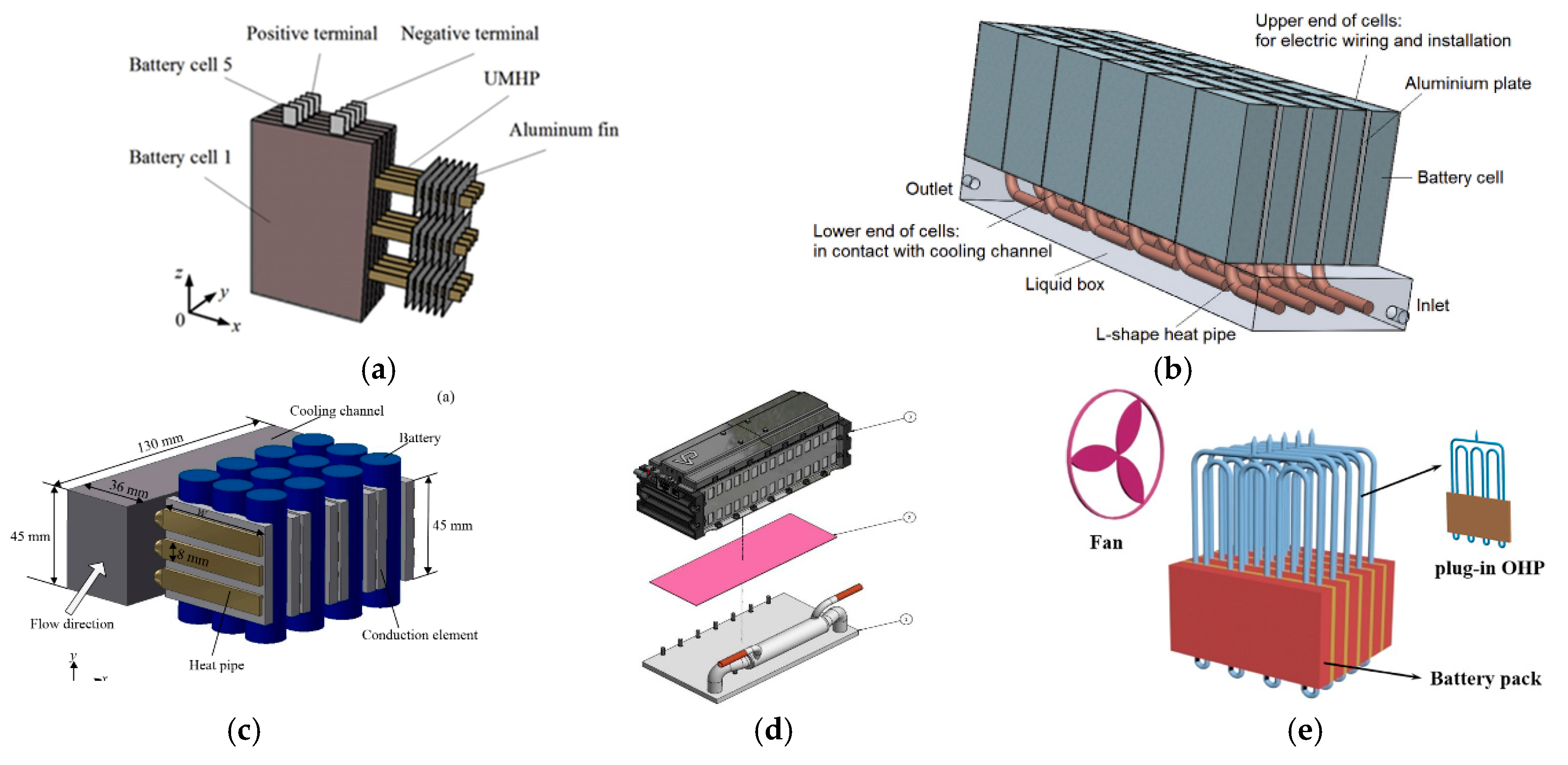
3.1. HP Coupled with Air- or Liquid-Cooling Method

Compared with HP-based BTMS in a passive cooling system, a hybrid BTMS obviously has better thermal performance with extra power consumption and a complicated structure. In this system, HP is always assisted by active cooling methods, including forced-air cooling (see Figure 4a) and liquid cooling (see Figure 4b). The BTMS in Figure 4a adopts an ultra-thin micro heat pipe (UMHP) coupled with a fan. Adding a UMHP can decrease T max by 7.1 °C from the beginning of discharging at a 2 C rate compared with that without HP and T max can be kept below 40 °C with a fan speed of 4 m/s [48]. Liu et al. [51] and Gan et al. [52] estimated and proved the necessity of employing cooling fluid in specific working experiments, respectively (see as Figure 4c). Hybrid BTMSs in these works could significantly reduce the temperature by about 14 °C in the 5C discharge rate compared with the natural cooling method. Jouhara et al. [53] (see as Figure 4d) applied a flat heat pipe (heat mat) in BTMS and used it to transfer the waste heat to an external liquid cooling medium. It was shown that the T max in the cell was kept below 28 °C. Wei et al. [54] (see as Figure 4e) developed a proof-of-concept plug-in pulsating heat pipe (PHP) with a flat-plate evaporator and tube condenser and found that PHP charged with ethanol-water mixtures had a quicker response and achieved superior thermal performance. Under the condition that the power input is 56 W, the battery pack’s average temperature can be kept below 46.5 °C.
Before using these systems, the enhancement of assisting active cooling methods should be evaluated. Liang et al. [31] found that when the ambient temperature is under 35 °C, reducing coolant temperature has a limited influence on the thermal performance, which means there is no need to use hybrid cooling methods. Another point is that the low temperature of the coolant could be harmful to the battery. Although decreasing the coolant temperature could lower T max , the inhomogeneity of temperature distribution reaches the peak and will be higher with the lower coolant temperature. The result is that the battery module’s available capacity and voltage decrease by nearly 1.17% and 0.88% when the coolant temperature is reduced by 10 °C at 5 C discharge [55].

3.2. PCM Coupled with Air or Liquid Active Cooling Method

Pure passive BTMS based on PCM or CPCM is always not enough to maintain the temperature of the battery pack in an appropriate range because of heat accumulation caused by the inefficient cooling of natural air cooling. In this way, active cooling strategies play an essential role in recovering the thermal energy storage capacity of PCMs. The BTMS in Figure 5a adopts CPCM (copper mesh and enhanced paraffin/expanded graphite) and copper fins exposed from the CPCM to enhance the heat transfer [57]. The BTMS in Figure 5b adopts cooling water pipes and PCM [58]. The structures of this kind of hybrid BTMSs are like the indirect contact mode in the liquid-based BTMS.
Cooling liquid pipes and LCP are the most common types, while PCM is filled between the pipe/LCP and battery cells. A common combination of PCM and liquid cooling adopts the mini-channel through the PCM in which HTF transfers heat with PCM. Rao et al. [59] investigated the effects of fluid flow rate, the number of channels, melting point and thermal conductivity of PCM on mini-channel/PCM-based BTMS. Bai et al. [60] developed a BTMS (see as Figure 6a). They found that PCM composed of 20% n-octadecane microcapsules and 80% water has superior performance, especially in the high target temperature when the mass flow rate does not exceed the threshold level. On the other hand, like the surface thermal contact mode in liquid cooling, the flow channels can also be attached to the PCM plate [61]. The cells, PCM and cooling plates are set in alignment [62] under compression. Bai et al. [63] designed a BTMS (see as Figure 6b), and the effects of different parameters were investigated. The LCP near the near-electrode area of the battery dissipates the majority of the heat generated by battery cells. At the same time, PCM increased thermal uniformity considerably.
There are some novel designs to increase the performance of hybrid BTMS adopting forced-air cooling coupled with PCM. Shi et al. [64] (see as Figure 6c) developed a BTMS and built an unsteady mathematical model. This BTMS is proved to have the ability to hold the battery temperature in an appropriate scope before the PCM completely melts. Jiang et al. [65] (see as Figure 6d) designed a BTMS adopting baffles to change the airflow direction in order to enhance its heat transfer. Situ et al. [66] (see as Figure 6e) developed a novel quaternary PCM plate consisting of paraffin, expanded graphite, low-density polyethylene and double copper mesh (DCM). Lazrak et al. [67] (see as Figure 6f) developed a novel BTMS based on PCM, and adopted a new way to enhance heat dissipation in the PCM by using copper grids. The two AI plates are on the two sides of the PCM and the battery cells. A fan was used to ventilate.
The geometry of heating has a remarkable influence on thermal performance. Typical shapes of battery cells are cylindrical, prismatic and pouch. If PCM is adopted in BTM, there is a need to design the shape of PCM to cover the battery cells, which achieves better thermal performance and less energy consumption. Safdari et al. [68] studied the effects of different shapes of container cross-sections, including circular, rectangular and hexagonal, on the thermal performance (see as Figure 7a). The conclusion is that a circular PCM container achieves superior performance with high latent heat, and rectangular PCM configuration is the most efficient due to its uniform air channel. Qin et al. [69] put forward a novel hybrid BTMS using forced air and PCM (see as Figure 7b). Compared with the passive BTMS, the maximum ∆T reduces by 1.2 °C and T max drops by 16 °C in the hybrid BTMS under a 3 C rate, respectively.
The system complexity is a problem for hybrid BTMS, but hybrid BTMS can cut down the weight and increase the efficiency of pure passive BTMS. Compared with basic active BTMS, PCM adds extra weight to the whole structure. Considering the heavier weight and larger volume of hybrid BTMS, Ling et al. [70] analyzed the influence of the composition of PCM, the set of the battery module, and the active cooling configuration on the heat-transfer capacity to minimize the mass of PCM used in BTMS. They found that the optimized design of this hybrid BTMS helps to save up to 94.1% in mass and 55.6% in volume of PCM.

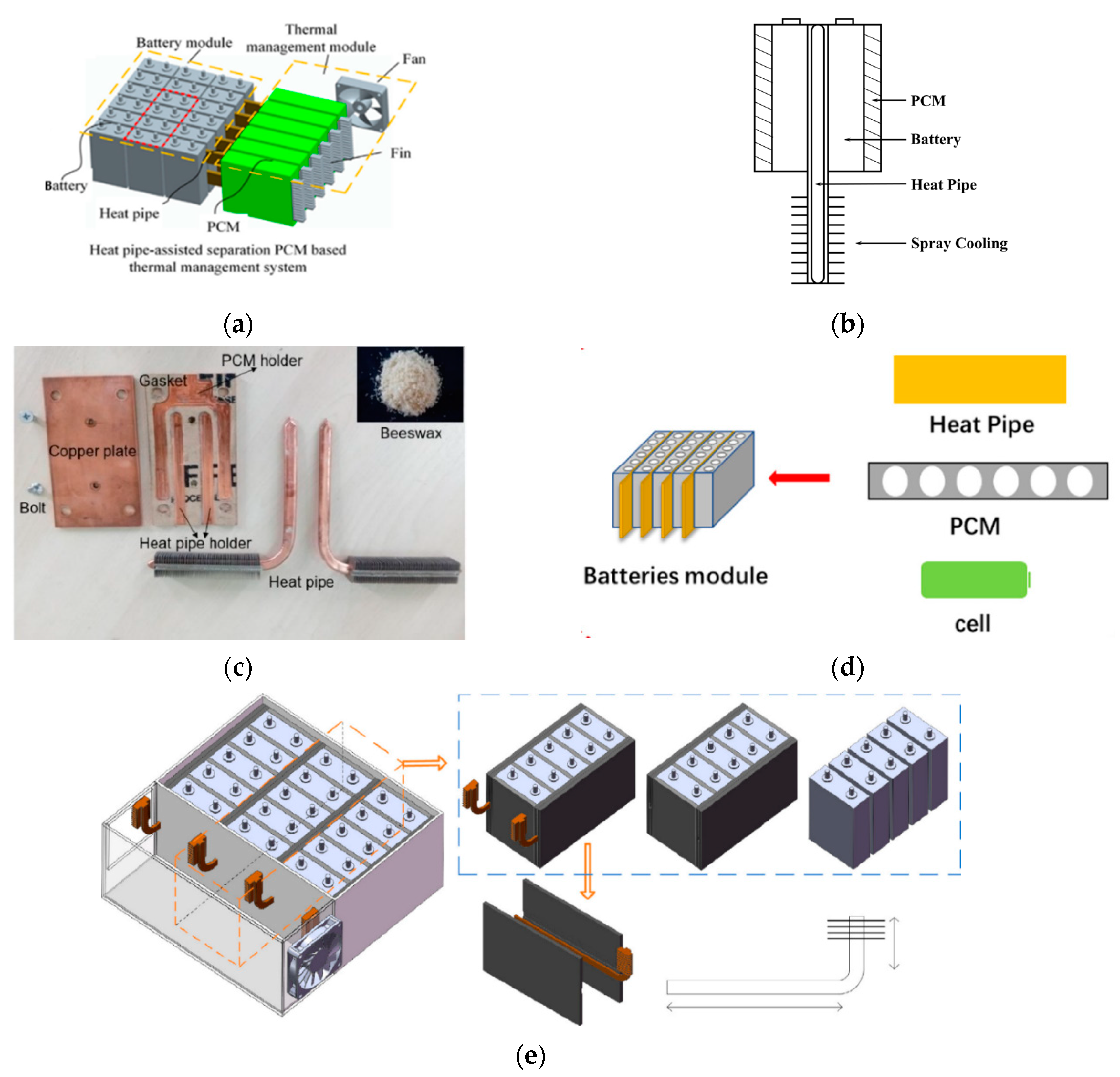
3.3. PCM Coupled with HP and Active Cooling Methods

PCM is easy to integrate into hybrid BTMS, and the adoption of PCM increases the thermal uniformity. Similar to the mode “PCM plus active cooling”, HP is adopted to solve the heat saturation in PCM due to its high efficiency and quick response. PCM could be filled between HP and HTF [71] (see as Figure 8a) or battery cells. Lei et al. [72] combined PCM, HP and spray cooling to manage the battery pack temperature (see as Figure 8b). This BTMS controls the temperature rise of the battery surface by less than 8 °C, even in 24 A discharge current and a high ambient temperature (40 °C). Amin et al. [73] design a BTMS (see as Figure 8c) that can maintain the battery temperature below 50 °C at the maximum heat load of 50 W. Huang et al. [74] designed a BTMS (see as Figure 8d), in which HP makes a huge contribution to heat transfer and thermal uniformity. Wu et al. [75] designed a HP-based BTMS assisted by PCM and forced-air cooling (see as Figure 8e). Even under the highest discharge rate (5 C), T m a x of the battery pack could be controlled below 50 °C. For this combination, the necessity of adopting HP in this kind of BTMS should be discussed. The result shows that when the discharge rate is low, air velocity doesn’t have a strong connection to the thermal performance due to the PCM.

3.4. Thermoelectric Cooling Coupled with Other Basic BTMS

Thermoelectric cooling (TEC) does not have a wide application on BTM of EV due to its low efficiency. However, it has been widely used in cooling electronics for its compact structure. Researchers add TEC in hybrid BTMS to enhance the heat transfer or achieve some special purposes. Figure 9 shows a typical structure of TEC in hybrid BTMS. Lyu et al. [76] combined TEC with active cooling methods. TEC transfers the heat from the condenser side and forced air assists TEC to move the heat to the outer space. The result shows that the temperature of the battery surface battery drops to 12 °C from 55 °C. Song et al. [77] designed a BTMS for standby batteries combining semiconductor thermoelectric device and PCMs (see as Figure 10) and tested the cooling time (14 h) and heat preservation (4.15 days) time in a circular way under the ambient temperature (323 K).

3.5. Liquid Coupled with Air

It is important to note that for nearly all liquid cooling methods, the hot liquid needs to be cooled down in a heat exchanger assisted by forced air. Cooling methods in this paper belong to hybrid BTMS because the forced air cooling is not applied to the battery pack directly. It is not necessary to employ both air path and HTF path for their different heat dissipation capacity and devices for most cases. There is no doubt that adding forced air into liquid-based BTMS can enhance the heat transfer in areas distant from LCP or other HTF channels.
Few researchers use forced-air cooling and liquid cooling simultaneously. A practical way is to combine LCP with forced-air cooling. Wang et al. [79] designed a BTMS under the space environment combining the gas circle and a LCP (see as Figure 11). They investigated the effects of different assembly structures, the intensity of the gas and liquid cycles on the thermal performance of BTMS. It was found that the structure with a fan under the LCP could make the flow field fully developed. Compared with pure LCP cooling in the vacuum packaged battery, the general Δ T and T max are reduced by 3.45 K and 3.88 K under the condition that the total heat generation is 576 W. The direct contact mode based on liquid cooling is hard to integrate with forced-air cooling.

4. Discussion

This paper puts forward a detailed classification rule to cover all existing BTMS and makes a clear division of active cooling methods based on liquids (direct or indirect, single phase or phase change, surface contact or channel contact). With regard to hybrid BTMS, these hybrid methods are divided into five groups and nine child items. The application and characteristics of every group are stated. There are some meaningful discussions about hybrid BTMS including necessity, design method and evaluation criterion.
Hybrid BTMS is the main trend in the development of BTMS and will apply to more applications, especially for extreme working situations. Hybrid BTMS also has some basic couples of single BTMS. And basically, we combine passive BTMS with active BTMS, which is shown to have great potential and practical use. However, not every situation is suitable for hybrid BTMS. Firstly, we need to balance cost and performance. According to the requirements of BTM, passive BTMS corresponds to low requirement (low heat load or short run time), while active BTMS satisfies higher requirements. According to the cost sensitivity, forced-air BTMS has a low cost while liquid cooling has a high consumption. For the combination of PCM and HP, if the ambient temperature is not very high, natural convection is enough, and forced air cooling is unnecessary. We need to consider natural air, forced air and liquid as a consequence and figure out the application condition of every method. Hybrid BTMS has more flexibility. If the battery output is required for high stability, PCM should be integrated to increase the thermal uniformity. TEC and HP could improve the local area’s heat transfer pertinently and have a fast response velocity. They can operate as an auxiliary device during a fast startup step.
Hybrid BTMS can overcome some disadvantages of basic BTMS, such as the heat saturation of PCM-based BTMS. Simultaneously, they are flexible and efficient so that the mass of HTF or PCM can be reduced in basic BTMS. However, there are some new problems like complexity and large energy consumption. We must estimate the cost of hybrid BTMS and then decide whether to adopt more complicated structures. It is suggested that we evaluate BTMSs with different indexes and give comprehensive evaluation scores. The BTMS is tested in different ways (discharging rates, test time and charging or cycling), and the evaluation indexes ( T max or Δ T ) are often different, which is not conducive to obtaining valid results through comparison. A dimensionless number is proposed to evaluate the performance of different BTMSs.
η = Actual   heat   accumulation Theoretical   heat   output = Δ T b · C b · M b + Δ T o · C o · M o ( I 2 α Δ P · Q v ) t
here, η , Δ T , C and M are PEI, temperature change, heat capacity and mass. The subscripts “b” and “o” correspond to the battery and its external structure, including PCM. I is the charge/discharge current, proportional to the charge/discharge rate. α represents the heating coefficient, and heat generation is assumed to be proportional to the second power of the current. Δ P is HTF-side pressure drop and Q v is the volume flow of HTF. t is testing time.
This PEI avoids a complex electrochemical model and takes power consumption and outer structures into consideration. For the accuracy of the evaluation, standard test conditions are needed, including standard charge/discharge rate and testing time. Under the same condition, we can compare BTMS from different research. Hybrid BTMS will occupy a larger proportion in the future BTMS, and has a broader range of applications other than EVs.

Author Contributions

C.Z. and B.Z. finished the main content of this paper; S.H. and Y.Z. drawed the figures; T.Y. designed the chart and table; X.L. guided the paper writing and proofreaded it. All authors contributed equally in the writing and revision of this paper. All authors have read and agreed to the published version of the manuscript.

Funding

This research was funded by the Youth Innovation Team of Shaanxi Universities and the Innovation and entrepreneurship project of Xi’an Jiaotong University (SJ202010698127).

Acknowledgments

This work was supported by the Faculty of School of Energy and Power in Xi’an Jiaotong University, Xi’an, China.

Conflicts of Interest

The authors declare no conflict of interest.

References

  1. US OEER. A Grand Challenge in Plug-In Electric Vehicles, Office of Energy Efficiency & RenewableEnergy. 2012. Available online: <energy.gov/vehiclesandfuels/pdfs/ev_everywhere/ev_everywhere_initial_framing_doc_081512_final_2.pdf> (accessed on 15 May 2020).
  2. Wu, W.; Wang, S.; Wu, W.; Chen, K.; Hong, S.; Lai, Y. A critical review of battery thermal performance and liquid based battery thermal management. Energ. Convers. Manag. 2019, 182, 262–281. [Google Scholar] [CrossRef]
  3. Bandhauer, T.M.; Garimella, S.; Fuller, T.F. A Critical Review of Thermal Issues in Lithium-Ion Batteries. J. Electrochem. Soc. 2011, 158, R1. [Google Scholar] [CrossRef]
  4. Tan, L.; Zhang, L.; Sun, Q.; Shen, M.; Qu, Q.; Zheng, H. Capacity loss induced by lithium deposition at graphite anode for LiFePO4/graphite cell cycling at different temperatures. Electrochim. Acta 2013, 111, 802–808. [Google Scholar] [CrossRef]
  5. Burow, D.; Sergeeva, K.; Calles, S.; Schorb, K.; Börger, A.; Roth, C.; Heitjans, P. Inhomogeneous degradation of graphite anodes in automotive lithium ion batteries under low-temperature pulse cycling conditions. J. Power Sources 2016, 307, 806–814. [Google Scholar] [CrossRef]
  6. Nagasubramanian, G. Electrical characteristics of 18650 Li-ion cells at low temperatures. J. Appl. Electrochem. 2001, 31, 99–104. [Google Scholar] [CrossRef]
  7. Jaguemont, J.; Boulon, L.; Venet, P.; Dubé, Y.; Sari, A. Low temperature aging tests for lithium-ion batteries. In Proceedings of the 2015 IEEE 24th International Symposium on Industrial Electronics (ISIE), Buzios, Rio de Janeiro, Brazil, 3–5 June 2015; pp. 1284–1289. [Google Scholar] [CrossRef]
  8. Saw, L.H.; Ye, Y.; Tay, A.A.O. Integration issues of lithium-ion battery into electric vehicles battery pack. J Clean. Prod. 2016, 113, 1032–1045. [Google Scholar] [CrossRef]
  9. Feng, X.; Xu, C.; He, X.; Wang, L.; Zhang, G.; Ouyang, M. Mechanisms for the evolution of cell variations within a LiNixCoyMnzO2/graphite lithium-ion battery pack caused by temperature non-uniformity. J Clean. Prod. 2018, 205, 447–462. [Google Scholar] [CrossRef]
  10. Basu, S.; Hariharan, K.S.; Kolake, S.M.; Song, T.; Sohn, D.K.; Yeo, T. Coupled electrochemical thermal modelling of a novel Li-ion battery pack thermal management system. Appl. Energ. 2016, 181, 1–13. [Google Scholar] [CrossRef]
  11. Sharma, A.K.; Birgersson, E.; Pan, F.; Wang, Q. Analysis of a Validated Mathematical Model for a Redox-Flow Lithium Ion Battery System. Electrochim. Acta 2017, 247, 183–192. [Google Scholar] [CrossRef]
  12. Tong, W.; Somasundaram, K.; Birgersson, E.; Mujumdar, A.S.; Yap, C. Thermo-electrochemical model for forced convection air cooling of a lithium-ion battery module. Appl. Therm. Eng. 2016, 99, 672–682. [Google Scholar] [CrossRef]
  13. Lin, X.; Perez, H.E.; Mohan, S.; Siegel, J.B.; Stefanopoulou, A.G.; Ding, Y.; Castanier, M.P. A lumped-parameter electro-thermal model for cylindrical batteries. J. Power Sources 2014, 257, 1–11. [Google Scholar] [CrossRef]
  14. Pesaran, A.A. Battery thermal models for hybrid vehicle simulations. J. Power Sources 2002, 110, 377–382. [Google Scholar] [CrossRef]
  15. Forgez, C.; Vinh Do, D.; Friedrich, G.; Morcrette, M.; Delacourt, C. Thermal modeling of a cylindrical LiFePO4/graphite lithium-ion battery. J. Power Sources 2010, 195, 2961–2968. [Google Scholar] [CrossRef]
  16. Mahamud, R.; Park, C. Spatial-resolution, lumped-capacitance thermal model for cylindrical Li-ion batteries under high Biot number conditions. Appl. Math Model. 2013, 37, 2787–2801. [Google Scholar] [CrossRef]
  17. Deng, T.; Ran, Y.; Yin, Y.; Liu, P. Multi-objective optimization design of thermal management system for lithium-ion battery pack based on Non-dominated Sorting Genetic Algorithm II. Appl. Therm. Eng. 2020, 164, 114394. [Google Scholar] [CrossRef]
  18. Panchal, S.; Dincer, I.; Agelin-Chaab, M.; Fraser, R.; Fowler, M. Thermal modeling and validation of temperature distributions in a prismatic lithium-ion battery at different discharge rates and varying boundary conditions. Appl. Therm. Eng. 2016, 96, 190–199. [Google Scholar] [CrossRef]
  19. Menale, C.; D’Annibale, F.; Mazzarotta, B.; Bubbico, R. Thermal management of lithium-ion batteries: An experimental investigation. Energy 2019, 182, 57–71. [Google Scholar] [CrossRef]
  20. Keyser, M.; Pesaran, A.; Li, Q.; Santhanagopalan, S.; Smith, K.; Wood, E.; Ahmed, S.; Bloom, I.; Dufek, E.; Shirk, M.; et al. Enabling fast charging—Battery thermal considerations. J. Power Sources 2017, 367, 228–236. [Google Scholar] [CrossRef]
  21. Grandjean, T.; Barai, A.; Hosseinzadeh, E.; Guo, Y.; McGordon, A.; Marco, J. Large format lithium ion pouch cell full thermal characterisation for improved electric vehicle thermal management. J. Power Sources 2017, 359, 215–225. [Google Scholar] [CrossRef] [Green Version]
  22. Hofmann, A.; Uhlmann, N.; Ziebert, C.; Wiegand, O.; Schmidt, A.; Hanemann, T. Preventing Li-ion cell explosion during thermal runaway with reduced pressure. Appl. Therm. Eng. 2017, 124, 539–544. [Google Scholar] [CrossRef]
  23. Wang, Q.; Jiang, B.; Li, B.; Yan, Y. A critical review of thermal management models and solutions of lithium-ion batteries for the development of pure electric vehicles. Renew. Sustain. Energy Rev. 2016, 64, 106–128. [Google Scholar] [CrossRef]
  24. Kim, J.; Oh, J.; Lee, H. Review on battery thermal management system for electric vehicles. Appl. Therm. Eng. 2019, 149, 192–212. [Google Scholar] [CrossRef]
  25. Siddique, A.R.M.; Mahmud, S.; Heyst, B.V. A comprehensive review on a passive (phase change materials) and an active (thermoelectric cooler) battery thermal management system and their limitations. J. Power Sources 2018, 401, 224–237. [Google Scholar] [CrossRef]
  26. Ianniciello, L.; Biwolé, P.H.; Achard, P. Electric vehicles batteries thermal management systems employing phase change materials. J. Power Sources 2018, 378, 383–403. [Google Scholar] [CrossRef]
  27. Jaguemont, J.; Van Mierlo, J. A comprehensive review of future thermal management systems for battery-electrified vehicles. J. Energy Storage 2020, 31, 101551. [Google Scholar] [CrossRef]
  28. Sun, H.; Dixon, R. Development of cooling strategy for an air cooled lithium-ion battery pack. J. Power Sources 2014, 272, 404–414. [Google Scholar] [CrossRef]
  29. Saw, L.H.; Tay, A.A.O.; Zhang, L.W. Thermal management of lithium-ion battery pack with liquid cooling. In Proceedings of the 2015 31st Thermal Measurement, Modeling & Management Symposium (SEMI-THERM), San Jose, CA, USA, 15–19 March 2015; pp. 298–302. [Google Scholar] [CrossRef]
  30. Chen, J.; Kang, S.; Jiaqiang, E.; Huang, Z.; Wei, K.; Zhang, F.; Zhang, B.; Zhu, H.; Deng, Y.; Liao, G. Effects of different phase change material thermal management strategies on the cooling performance of the power lithium ion batteries: A review. J. Power Sources 2019, 442, 227228. [Google Scholar] [CrossRef]
  31. Liang, J.; Gan, Y.; Li, Y. Investigation on the thermal performance of a battery thermal management system using heat pipe under different ambient temperatures. Energ. Convers. Manag. 2018, 155, 1–9. [Google Scholar] [CrossRef]
  32. Chen, K.; Chen, Y.; She, Y.; Song, M.; Wang, S.; Chen, L. Construction of effective symmetrical air-cooled system for battery thermal management. Appl. Therm. Eng. 2019, 166, 114679. [Google Scholar] [CrossRef]
  33. Liu, Y.; Zhang, J. Design a J-type air-based battery thermal management system through surrogate-based optimization. Appl. Energ. 2019, 252, 113426. [Google Scholar] [CrossRef]
  34. Yu, K.; Yang, X.; Cheng, Y.; Li, C. Thermal analysis and two-directional air flow thermal management for lithium-ion battery pack. J. Power Sources 2014, 270, 193–200. [Google Scholar] [CrossRef]
  35. Mahamud, R.; Park, C. Reciprocating air flow for Li-ion battery thermal management to improve temperature uniformity. J. Power Sources 2011, 196, 5685–5696. [Google Scholar] [CrossRef]
  36. Park, S.; Jung, D. Battery cell arrangement and heat transfer fluid effects on the parasitic power consumption and the cell temperature distribution in a hybrid electric vehicle. J. Power Sources 2013, 227, 191–198. [Google Scholar] [CrossRef]
  37. Baidu Wenku. Available online: https://wenku.baidu.com/view/68526c522079168884868762caaedd3383c4b587.html. (accessed on 1 October 2020).
  38. Zhang, S.; Zhao, R.; Liu, J.; Gu, J. Investigation on a hydrogel based passive thermal management system for lithium ion batteries. Energy 2014, 68, 854–861. [Google Scholar] [CrossRef]
  39. Ren, Y.; Yu, Z.; Song, G. Thermal management of a Li-ion battery pack employing water evaporation. J. Power Sources 2017, 360, 166–171. [Google Scholar] [CrossRef]
  40. Al-Zareer, M.; Dincer, I.; Rosen, M.A. Novel thermal management system using boiling cooling for high-powered lithium-ion battery packs for hybrid electric vehicles. J. Power Sources 2017, 363, 291–303. [Google Scholar] [CrossRef]
  41. Chung, Y.; Kim, M.S. Thermal analysis and pack level design of battery thermal management system with liquid cooling for electric vehicles. Energ. Convers. Manag. 2019, 196, 105–116. [Google Scholar] [CrossRef]
  42. Karimi, G.; Dehghan, A.R. Thermal analysis of high-power lithium-ion battery packs using flow network approach. Int. J. Energ. Res. 2014, 38, 1793–1811. [Google Scholar] [CrossRef]
  43. Rao, Z.; Qian, Z.; Kuang, Y.; Li, Y. Thermal performance of liquid cooling based thermal management system for cylindrical lithium-ion battery module with variable contact surface. Appl. Therm. Eng. 2017, 123, 1514–1522. [Google Scholar] [CrossRef]
  44. Sharma, R.K.; Ganesan, P.; Tyagi, V.V.; Metselaar, H.S.C.; Sandaran, S.C. Developments in organic solid–liquid phase change materials and their applications in thermal energy storage. Energ. Convers. Manag. 2015, 95, 193–228. [Google Scholar] [CrossRef] [Green Version]
  45. Temel, U.N. Passive thermal management of a simulated battery pack at different climate conditions. Appl. Therm. Eng. 2019, 158, 113796. [Google Scholar] [CrossRef]
  46. Zhao, Y.; Zou, B.; Li, C.; Ding, Y. Active cooling based battery thermal management using composite phase change materials. Energy Procedia 2019, 158, 4933–4940. [Google Scholar] [CrossRef]
  47. Kizilel, R.; Sabbah, R.; Selman, J.R.; Al-Hallaj, S. An alternative cooling system to enhance the safety of Li-ion battery packs. J. Power Sources 2009, 194, 1105–1112. [Google Scholar] [CrossRef]
  48. Liu, F.; Lan, F.; Chen, J. Dynamic thermal characteristics of heat pipe via segmented thermal resistance model for electric vehicle battery cooling. J. Power Sources 2016, 321, 57–70. [Google Scholar] [CrossRef]
  49. Zhang, Z.; Wei, K. Experimental and numerical study of a passive thermal management system using flat heat pipes for lithium-ion batteries. Appl. Therm. Eng. 2020, 166, 114660. [Google Scholar] [CrossRef]
  50. Bandhauer, T.M.; Garimella, S. Passive, internal thermal management system for batteries using microscale liquid–vapor phase change. Appl. Therm. Eng. 2013, 61, 756–769. [Google Scholar] [CrossRef]
  51. Liu, W.; Jia, Z.; Luo, Y.; Xie, W.; Deng, T. Experimental investigation on thermal management of cylindrical Li-ion battery pack based on vapor chamber combined with fin structure. Appl. Therm. Eng. 2019, 162, 114272. [Google Scholar] [CrossRef]
  52. Gan, Y.; Wang, J.; Liang, J.; Huang, Z.; Hu, M. Development of thermal equivalent circuit model of heat pipe-based thermal management system for a battery module with cylindrical cells. Appl. Therm. Eng. 2020, 164, 114523. [Google Scholar] [CrossRef]
  53. Jouhara, H.; Serey, N.; Khordehgah, N.; Bennett, R.; Almahmoud, S.; Lester, S.P. Investigation, development and experimental analyses of a heat pipe based battery thermal management system. Int. J. Therm. 2012, 1–2, 100004. [Google Scholar] [CrossRef]
  54. Wei, A.; Qu, J.; Qiu, H.; Wang, C.; Cao, G. Heat transfer characteristics of plug-in oscillating heat pipe with binary-fluid mixtures for electric vehicle battery thermal management. Int. J. Heat Mass Tran. 2019, 135, 746–760. [Google Scholar] [CrossRef]
  55. Liang, J.; Gan, Y.; Li, Y.; Tan, M.; Wang, J. Thermal and electrochemical performance of a serially connected battery module using a heat pipe-based thermal management system under different coolant temperatures. Energy 2019, 189, 116233. [Google Scholar] [CrossRef]
  56. Wang, Q.; Jiang, B.; Xue, Q.F.; Sun, H.L.; Li, B.; Zou, H.M.; Yan, Y.Y. Experimental investigation on EV battery cooling and heating by heat pipes. Appl. Therm. Eng. 2015, 88, 54–60. [Google Scholar] [CrossRef]
  57. Wu, W.; Yang, X.; Zhang, G.; Ke, X.; Wang, Z.; Situ, W.; Li, X.; Zhang, J. An experimental study of thermal management system using copper mesh-enhanced composite phase change materials for power battery pack. Energy 2016, 113, 909–916. [Google Scholar] [CrossRef]
  58. Hekmat, S.; Molaeimanesh, G.R. Hybrid thermal management of a Li-ion battery module with phase change material and cooling water pipes: An experimental investigation. Appl. Therm. Eng. 2020, 166, 114759. [Google Scholar] [CrossRef]
  59. Rao, Z.; Wang, Q.; Huang, C. Investigation of the thermal performance of phase change material/mini-channel coupled battery thermal management system. Appl. Energ. 2016, 164, 659–669. [Google Scholar] [CrossRef]
  60. Bai, F.; Chen, M.; Song, W.; Yu, Q.; Li, Y.; Feng, Z.; Ding, Y. Investigation of thermal management for lithium-ion pouch battery module based on phase change slurry and mini channel cooling plate. Energy 2019, 167, 561–574. [Google Scholar] [CrossRef]
  61. Zhang, T.; Zhang, D.; Gao, Q.; Wang, Y.; Wang, G.; Gu, Y.; Bao, W. Investigation on the promotion of temperature uniformity for the designed battery pack with liquid flow in cooling process. Appl. Therm. Eng. 2017, 116, 655–662. [Google Scholar] [CrossRef]
  62. Javani, N.; Dincer, I.; Naterer, G.F.; Rohrauer, G.L. Modeling of passive thermal management for electric vehicle battery packs with PCM between cells. Appl. Therm. Eng. 2014, 73, 307–316. [Google Scholar] [CrossRef]
  63. Bai, F.; Chen, M.; Song, W.; Feng, Z.; Li, Y.; Ding, Y. Thermal management performances of PCM/water cooling-plate using for lithium-ion battery module based on non-uniform internal heat source. Appl. Therm. Eng. 2017, 126, 17–27. [Google Scholar] [CrossRef]
  64. Shi, S.; Xie, Y.; Li, M.; Yuan, Y.; Yu, J.; Wu, H.; Liu, B.; Liu, N. Non-steady experimental investigation on an integrated thermal management system for power battery with phase change materials. Energ. Convers. Manag. 2017, 138, 84–96. [Google Scholar] [CrossRef] [Green Version]
  65. Jiang, G.; Huang, J.; Liu, M.; Cao, M. Experiment and simulation of thermal management for a tube-shell Li-ion battery pack with composite phase change material. Appl. Therm. Eng. 2017, 120, 1–9. [Google Scholar] [CrossRef]
  66. Situ, W.; Zhang, G.; Li, X.; Yang, X.; Wei, C.; Rao, M.; Wang, Z.; Wang, C.; Wu, W. A thermal management system for rectangular LiFePO4 battery module using novel double copper mesh-enhanced phase change material plates. Energy 2017, 141, 613–623. [Google Scholar] [CrossRef]
  67. Lazrak, A.; Fourmigué, J.; Robin, J. An innovative practical battery thermal management system based on phase change materials: Numerical and experimental investigations. Appl. Therm. Eng. 2018, 128, 20–32. [Google Scholar] [CrossRef]
  68. Safdari, M.; Ahmadi, R.; Sadeghzadeh, S. Numerical investigation on PCM encapsulation shape used in the passive-active battery thermal management. Energy 2020, 193, 116840. [Google Scholar] [CrossRef]
  69. Qin, P.; Liao, M.; Zhang, D.; Liu, Y.; Sun, J.; Wang, Q. Experimental and numerical study on a novel hybrid battery thermal management system integrated forced-air convection and phase change material. Energ. Convers. Manag. 2019, 195, 1371–1381. [Google Scholar] [CrossRef]
  70. Ling, Z.; Cao, J.; Zhang, W.; Zhang, Z.; Fang, X.; Gao, X. Compact liquid cooling strategy with phase change materials for Li-ion batteries optimized using response surface methodology. Appl. Energ. 2018, 228, 777–788. [Google Scholar] [CrossRef]
  71. Zhang, W.; Qiu, J.; Yin, X.; Wang, D. A novel heat pipe assisted separation type battery thermal management system based on phase change material. Appl. Therm. Eng. 2020, 165, 114571. [Google Scholar] [CrossRef]
  72. Lei, S.; Shi, Y.; Chen, G. A lithium-ion battery-thermal-management design based on phase-change-material thermal storage and spray cooling. Appl. Therm. Eng. 2020, 168, 114792. [Google Scholar] [CrossRef]
  73. Amin, M.; Ariantara, B.; Putra, N.; Sandi, A.F.; Abdullah, N.A. Thermal Management of Electric Vehicle Batteries Using Heat Pipe and Phase Change Materials. E3S Web Conf. 2018, 67, 03034. [Google Scholar] [CrossRef]
  74. Huang, Q.; Li, X.; Zhang, G.; Zhang, J.; He, F.; Li, Y. Experimental investigation of the thermal performance of heat pipe assisted phase change material for battery thermal management system. Appl. Therm. Eng. 2018, 141, 1092–1100. [Google Scholar] [CrossRef]
  75. Wu, W.; Yang, X.; Zhang, G.; Chen, K.; Wang, S. Experimental investigation on the thermal performance of heat pipe-assisted phase change material based battery thermal management system. Energ. Convers. Manag. 2017, 138, 486–492. [Google Scholar] [CrossRef]
  76. Lyu, Y.; Siddique, A.R.M.; Majid, S.H.; Biglarbegian, M.; Gadsden, S.A.; Mahmud, S. Electric vehicle battery thermal management system with thermoelectric cooling. Energy Rep. 2019, 5, 822–827. [Google Scholar] [CrossRef]
  77. Song, W.; Bai, F.; Chen, M.; Lin, S.; Feng, Z.; Li, Y. Thermal management of standby battery for outdoor base station based on the semiconductor thermoelectric device and phase change materials. Appl. Therm. Eng. 2018, 137, 203–217. [Google Scholar] [CrossRef] [Green Version]
  78. Li, X.; Zhong, Z.; Luo, J.; Wang, Z.; Yuan, W.; Zhang, G.; Yang, C.; Yang, C. Experimental Investigation on a Thermoelectric Cooler for Thermal Management of a Lithium-Ion Battery Module. Int. J. Photoenergy 2019, 2019, 1–10. [Google Scholar] [CrossRef] [Green Version]
  79. Wang, S.; Li, Y.; Li, Y.; Mao, Y.; Zhang, Y.; Guo, W.; Zhong, M. A forced gas cooling circle packaging with liquid cooling plate for the thermal management of Li-ion batteries under space environment. Appl. Therm. Eng. 2017, 123, 929–939. [Google Scholar] [CrossRef]
Figure 1. Classification of battery thermal management systems (BTMS).
Energies 13 06257 g001
Figure 2. Designs of the flow channel and flow pattern (a,b,d,e) “Z-type” flow channel, Symmetrically modified “Z-type”, “U-type” flow channel, Symmetrically modified “U-type” [1], (c) Tapered “Z-type” [2], (f) Tapered “U-type”, (g) Additional duct, Reprint with permission [34]; 2020, Elsevier. (h) Reciprocating air flow in two directions. Reprint with permission [35]; 2020, Elsevier.
Energies 13 06257 g002
Figure 3. Classification of liquid cooling and corresponding classic examples [40,41,42,43].
Energies 13 06257 g003
Figure 4. Examples for HP-based hybrid BTMS coupled with active cooling methods. (a) Hybrid BTMS with an ultra-thin micro heat pipe, Reprint with permission [48]; 2020, Elsevier., (b) HP-based BTMS associated with liquid cooling, Reprint with permission [56]; 2020, Elsevier., (c) A HP-based BTMS with cylindrical battery cells, Reprint with permission [52]; 2020, Elsevier., (d) Battery module is set above the heat mat [3], (e) Plug-in oscillating heat pipes (OHPs) are sandwiched by battery packs. Reprint with permission [54]; 2020, Elsevier.
Energies 13 06257 g004
Figure 5. Examples for PCM-based hybrid BTMS (a) PCM+Air. Reprint with permission [57]; 2020, Elsevier., (b) PCM+Liquid. Reprint with permission [58]; 2020, Elsevier.
Energies 13 06257 g005
Figure 6. Classic structures of hybrid BTMS combining PCM with air or liquid active cooling method. (a) Combination of phase change slurry and mini channel liquid cold plate (LCP). Reprint with permission [60]; 2020, Elsevier. (b) Combination of PCM with LCP. Reprint with permission [63]; 2020, Elsevier. (c) PCM-based BTMS assisted with air cooling. The phase change storage energy unit (PCSEU) is made up of a copper foam and n-Eicosane. Reprint with permission [64]; 2020, Elsevier. (d) Integration of CPCM consisted of expanded graphite and paraffin and forced air cooling Reprint with permission [65]; 2020, Elsevier. (e) BTMS with a novel quaternary PCM and DCM Reprint with permission [66]; 2020, Elsevier.. (f) PCM-based BTMS with copper grids. Reprint with permission [67]; 2020, Elsevier.
Energies 13 06257 g006aEnergies 13 06257 g006b
Figure 7. The geometry in PCM-based hybrid BTMS (a) Three different shapes of the cross section for PCM-based BTMS Reprint with permission [68]; 2020, Elsevier.; (b) Schematic of a PCM-based BTMS. Reprint with permission [69]; 2020, Elsevier.
Energies 13 06257 g007
Figure 8. Classic examples of hybrid BTMS associated with PCM and HP (a) HP-assisted PCM based BTMS. Reprint with permission [71]; 2020, Elsevier. (b) HP-assisted PCM associated with spray cooling. Reprint with permission [72]; 2020, Elsevier. (c) Adopting ‘L’ type of HP and beeswax PCM [73]. (d) Combination of PCM and HP assisted by air/liquid cooling. Reprint with permission [74]; 2020, Elsevier. (e) Each HP was set between two PCM plates and embedded in the surface of PCM plates. Reprint with permission [75]; 2020, Elsevier.
Energies 13 06257 g008
Figure 9. The schematic diagram of TEC in hybrid BTMS [78].
Energies 13 06257 g009
Figure 10. A classic example of hybrid BTMS of PCM coupled with TEC. Reprint with permission [77]; 2020, Elsevier.
Energies 13 06257 g010
Figure 11. A classic example of BTMS based on liquid coupled with air. Reprint with permission [79]; 2020, Elsevier.
Energies 13 06257 g011
Table 1. Main types of hybrid BTMS.
TypeHybrid BTMSRemark
HP coupled with air or liquid active coolingHP+Air
  • Active cooling methods enhance the heat transfer process in passive cooling methods. Combining them is the basic idea of hybrid BTMS.
  • The enhanced effect of liquid cooling is more robust than air, but forced air cooling is enough if the heat load is low.
  • Adding PCM increases the thermal uniformity and overall thermal performance due to the substantial latent heat. Active cooling methods solve the heat saturation problem in pure PCM-BTMS.
  • HP and TEC enhance the local heat transfer significantly quickly. A combination of HP/TEC and PCM has better performance and stability. HP can increase the performance by adjusting the shape of its heat sink.
HP+Liquid
PCM coupled with HPPCM+HP
PCM+HP+Air
PCM+HP+Liquid
PCM coupled with air or liquid active coolingPCM+Liquid
PCM+Air
TEC coupled with other BTMSTEC+Air+Liquid
PCM+TEC
Liquid coupled with airLiquid+Air
Publisher’s Note: MDPI stays neutral with regard to jurisdictional claims in published maps and institutional affiliations.

