Article

Design and Fabrication of Solar Thermal Energy Storage System Using Potash Alum as a PCM

1
Electrical Construction Division, Tribal Areas Electric Supply Company (TESCO), Peshawar 25000, Pakistan
2
Department of Mechanical Engineering, Ghulam Ishaq Khan Institute of Science & Technology, Swabi, Khyber Pakhtunkhwa 23640, Pakistan
3
Department of Electrical Engineering, Air University, Islamabad, Kamra Campus, Kamra 43570, Pakistan
4
Department of Electrical Engineering & Technology, Ripah International University, Faisalabad Campus, Punjab 38000, Pakistan
5
Department of Electrical Engineering, Yeungnam University, 280, Daehak-Ro, Gyeongsangbuk do 38541, Korea
6
Department of Mechanical Engineering, Air University, Islamabad, Kamra Campus, Kamra 43570, Pakistan
7
Department of Aeropsace Engineering, Air University, Islamabad, Kamra Campus, Kamra 43570, Pakistan
*
Authors to whom correspondence should be addressed.
Energies 2020, 13(23), 6169; https://doi.org/10.3390/en13236169
Submission received: 12 October 2020 / Revised: 20 November 2020 / Accepted: 22 November 2020 / Published: 24 November 2020

Abstract

:
Renewable energy resources like solar energy, wind energy, hydro energy, photovoltaic etc. are gaining much importance due to the day by day depletion of conventional resources. Owing to the lower efficiencies of renewable energy resources, much attention has been paid to improving them. The concept of utilizing phase change materials (PCMs) has attracted wide attention in recent years. This is due to their ability to extract thermal energy when used in collaboration with photovoltaic (PV), thus improving the photoelectric conversion efficiency. In this paper, the objective is to design and fabricate a novel thermal energy storage system using phase change material. An investigation on the characteristics of Potash Alum as a phase change material due to its low cost, easy availability and its usage as an energy storage for the indoor purposes are taken into account. The use of a latent heat storage system using phase change materials (PCMs) is an effective way of storing thermal energy and has the advantage of high-energy storage density and the isothermal nature of the storage process. In the current study, potash alum was identified as a phase change material combined with renewable energy sources, that can be efficiently and effectively used in storing thermal energy at compartively lower temperatures that can later be used in daily life heating requirements.A parabolic dish which acts of a heat collector is used to track and reflects solar radiation at a single point on a receiver tank. Heat transfer from the solar collector to the storage tank is done by using a circulating heat transfer fluid with the help of a pump. The experimental results show that this system is capable of successfully storing and utilizing thermal energy on indoor scale such as cooking, heating and those applications where temperature is below 92 °C.

1. Introduction

Renewable energy is playing a vital role in the clean energy generation and avoiding hazardous and negative effects of pollutions in our environment. The use of different renewable energy sources like hydroelectric, wind, solar, tidal is increasing day by day with the addition of thousands of megawatts to the grid systems. Photovoltaic (PV) technology, which converts solar irradiance directly into electricity, has made tremendous progress on the scientific as well as the commercial scale. Still the research and development continues to push its efficiency along with lowering its cost [1,2]. On the other hand, photovoltaics are already used but the problem is that of the system durability and low expenditure because panels don’t work the same over time. Similarly, storage batteries are also very expensive and not long lasting. However, along with other barriers, the prime barrier is that of intermittent sunlight which is available for only a portion of a day. Hence, incorporating efficient energy storage systems along with renewable energy sources is becoming essential with time [3,4]. The traditional mechanism for the solar energy storage is first converting solar energy into electrical energy through photovoltaic panels and then storing it in a batteries which are expensive [5]. In recent years, few researchers have proposed the usage of phase change materials (PCMs) as an alternative method for the storage of solar energy [6]. In this method, the solar energy is converted into thermal energy using PCMs and then stored into storage tank which acts as a thermal battery [7,8]. In thermal energy storage, the useful energy is transferred to the storage medium and stored in the form of latent and sensible heat during the phase transition process with a minimum rise in temperature. Among the two, latent heat storage is more attractive than the sensible heat storage system because of its high temperature swing and relatively small size [9].
In latent heat storage system, radiation from the sun fall on a parabolic concentrator which directs the incident radiation toward the base of the receiver tank resulting in the temperature rise of the heat transfer fluid (HTF), hence storing energy in the form of sensible heat for a specific period of time. The receiver tank is connected to a storage tank by rubber pipes and HTF is circulated in them at a constant flow rate with the help of a small pump. As the hot HTF flows in the storage tank, the heat is supplied to the PCM situated inside the storage tank which changes its state [10,11,12]. The bulk amount of heat (latent heat) used to change the phase of PCM can be stored by using effective insulation. The storage tank is also connected to a heating application by using pipes. Valves are used to direct the flow of HTF within the receiver tank and storage tank to store the energy during the availability of the solar energy and from storage tank to the heating application when the stored energy is to be used.
Several types of solar energy storage devices using different PCMs like paraffin, perlite, metal foam and beeswax [13,14,15] are used. The selection of suitable PCM for a particular application requires a lot of factors to be taken into consideration. These PCMs are classified into organic and inorganic, with the later PCMs are costly and not readily available [16,17,18]. Bushnell and Sohi designed a modular phase change heat exchanger with pentaerythritol as PCM for thermal storage and tested it in an oven with circulating heat transfer oil with a pattern of electrical heating to stimulate the concentrating solar collector. The comparative analysis of thermal energy retention times and cooking extraction times with efficiencies were assessed with reported non-modular heat exchanger. The results indicated that foods were cooked at temperatures between 95–97 degrees [19]. Sharma and his team used commercial grade acetamide as a latent heat storage material with significant values of melting point and latent heat of fusion, designed a cylindrical PCM storage unit for box-type solar cookers and to utilized it for late evening cooking. This unit provides higher heat transfer between PCM and cooking and consumes less time for cooking. It is proved that storage of solar energy doesn’t affect the performance of solar cookers for late evening cooking, thus having a PCM melting temperature between 105–110 °C is needed and this design can be implemented for late-evening cooking as well. The only thing to be considered for this design is to identify a material with appropriate melting point, concentration and quantity [20]. Buddhi used acetanilide with a melting point of 118.9 °C and latent heat of fusion as 222 kj/kg as a PCM for night cooking [21]. Thus the proper significance and the assessment of the materials with capability of increasing melting point and higher latent heat of fusion can be tried by further experiments.
Schmerse et al. [22] studied PCM materials in building design. They concluded that PCM incorporated in the construcition of buildings can save up to 27% of the energy consumption annually. Nems and Puertas [23] experimentally studied a dual PCM for heat storage, they made a I–D model for dual PCM and validated their results using experimental results. Leang et al. [24] performed design and optimization of composite walls by integrating a PCM in their design. Their study concluded that the higher the latent heat, the lower the heating demand and greater the thermal comfort of the interior of the house. Pasupathi et al. [25] studied a hybrid PCM that included nano-particles for the purpose of a thermal energy storage system. Their study concluded that utilizing a hybrid PCM material can increase the performance of PCM if the mass fraction of the nanomaterial is 1.0. In all the aforementioned studies, different PCM materials were employed for thermal energy storage. There is no specific studies that employed potash alum as PCM with a renewable energy source for thermal energy storage systems. In the current study, potash alum is used as PCM because it is cheap and readily available on the market.
The aim of this study was to design and study a latent heat thermal energy storage system which can store solar energy for a reasonable amount of time. This stored energy is environmentally friendly and can be used for any indoor heating purpose such as cooking, water and room heating applications in the absence of sunlight. The experimental results of the designed system show that the system is capable of storing enough energy during sunshine hours which can later be used for any heating application in the absence of sunlight.
This research article has been organized as follows: In Section 2 the system design is discussed and analyzed. Simulations are performed and results are presented in Section 3. Section 4 is about the fabrication of the system, whereas, Section 5 throws light on the experimental results and discussion

2. Design and Analysis

2.1. Design Requirements

Heat required for the purpose of cooking through heater can be calculated using Equation (1):
Q = P h × t
The heat losses cannot be ignored in every real system. Total heat required incorporating heat loss can be calculated using Equation (2):
Q T = Q + Q l
The required design parameters are summarized in Table 1.
For the purpose of encapsulating the PCM, several tests were done on small one inch and half inch pipes as PCM encapsulating materials since they are effective and can be cheaply manufactured.

2.2. Selection of Potash Alum as PCM and Heat Transfer Fluid

It is possible to find materials with a heat of fusion and melting temperature in the desired range (184 kJ/kg, 92 °C) but a material has to exhibit certain properties to become a feasible PCM. The properties and characteristics required for selection of a phase change material desired for heat storage are shown in Table 2.
Based upon the above properties and special consideration to economics and thermal stability of the PCM, potash alum, which is readily available in the market, was selected as a suitable PCM for latent thermal energy storage systems [28]. Its melting temperature is about 92 °C, which is why it is suitable for cooking or for heating water which is near to our target range of 95–97 °C. The latent heat of potash alum is about 184 kJ/kg, which is very high compared to rest of PCMs. Potash alum is a PCM with exceptional stability behavior [29]. Table 3 shows the characteristics of the potash alum and its suitability as a phase change material. Thermal stability is an extremely important characteristic to select a PCM as the material has to withstand several heating and cooling cycles in order to ensure the efficient functioning of the thermal system. Therefore several tests were carried out with eutectic salt mixtures and potash alum to check which one is the most thermally stable. Firstly, the eutectic salt Al2O3 (66%) and NaCl (34%) were encapsulated, which melted twice and by the third cycle it was rock solid. Secondly, potsh alum was encapsulated, melted and solidified 30 times and every time the material melted easily and did not show degradation which demonstrates the good stability characteristics of potash alum.
The selection criteria for heat transfer fluid is based on the specific heat density, boiling point, decomposition point, viscosity and availability of the fluid [30,31]. Among the other heat transfer fluids, water has a boiling point of 100 °C at 1 atm and highest specific heat (4.184 kJ/kg-K). However, adding ethylene glycol to water increases its melting point significantly and reduces its specific heat slightly [32], so a mixture of 30% ethylene glycol and 70% water was selected as a heat transfer fluid in this study.

2.3. Modeling and Design of Storage Tank

The mass of phase change material required for the storage of heat is calculated using Equation (3). Where QT is the value of heat required for cooking and hm stands for the heat of fusion of potash alum:
m p c m = Q T h m
The total heat storage capacity of a latent heat system in the concrete case of solid-liquid transformation incorporating sensible heat can be found by knowing the values of the mass of phase change material (mpcm), specific heat of the potash alum in the liquid phase (Melted) (Clp), the specific heat of the potash alum in the liquid phase (Csp), melted fraction (am), heat of fusion of potash alum (hm), melting point of potash alum (Tm), initial temperature (Ti) and final temperature (Tf) using Equation (4):
Q p c m = m p c m × ( ( a m × h m ) + ( C s p × ( T m T i ) ) + ( C l p × ( T f T m ) ) )
The increase in energy occurs due to   C s p × ( T m T i ) + C l p × ( T f T m ) , which represents the sensible heat. This sensible heat is lost very quickly, so the useful energy to be considered is the latent energy of the PCM which is to be calculated from the PCM mass. This means that the PCM material considered in the study has sufficient capacity to store the required amount of heat. The required volume of the potash alum (PCM) can be calculated using Equation (5):
V p c m = m ρ l
The length of the PCM tubes (Lpcmt) can be calculated using Equation (6) where Vpcm stands for PCM volume, dit for inner diameter of tubes and n for number of tubes:
L p c m t = ( V × 4 ) ( π × n × d i t 2 )
The length of the storage tank (Lst) can be found from the length of PCM tube using Equation (7):
L s t = L p c m t + 0.03
The inner inlet area of the storage tank is calculated using Equation (8), where rii stands for the radius of the storage tank:
A i = π × r i i 2
The mass flow rate of HTF is calculated using Equation (9), where ρ H T F stands for the density of HTF and q ˙ stands for the volume flow rate:
m = ˙   ρ H T F × q ˙
The velocity of the HTF at the inlet is calculated using Equation (10):
u = q ˙ A i
The Reynold’s number for the HTF is calculated using Equation (11) which specifies the flow pattern of a fluid. A low Reynold’s number indicates laminar flow, whereas a high Reynold’s number indicates turbulent flow. μ H T F   stands for the velocity of the HTF:
R e = ρ H T F × u × 2 × r i i μ H T F
The results calculated above for the design parameters of the storage tank, PCM and HTF are summarized in Table 3.
In order to get an idea how much time it takes to melt the PCM material within the tank (charging time) and also how much time can the energy be stored within the storage tank (storing time) we use two separate simulation studies.
A 2D model of the latent energy storage tank is constructed in COMSOL, a software used for simulation-based modeling and designing physical and mechanical structures. The COMSOL software is used to analyze the temperature and phase change results of PCM material after a specific amount of charging and storing time. The geometry of the 2D model is shown in the Figure 1. The HTF enter through the inlet and exits through outlet, and transfer heat throughout the storage tank container which contains a cross section of 10 PCM tubes as shown in Figure 1.

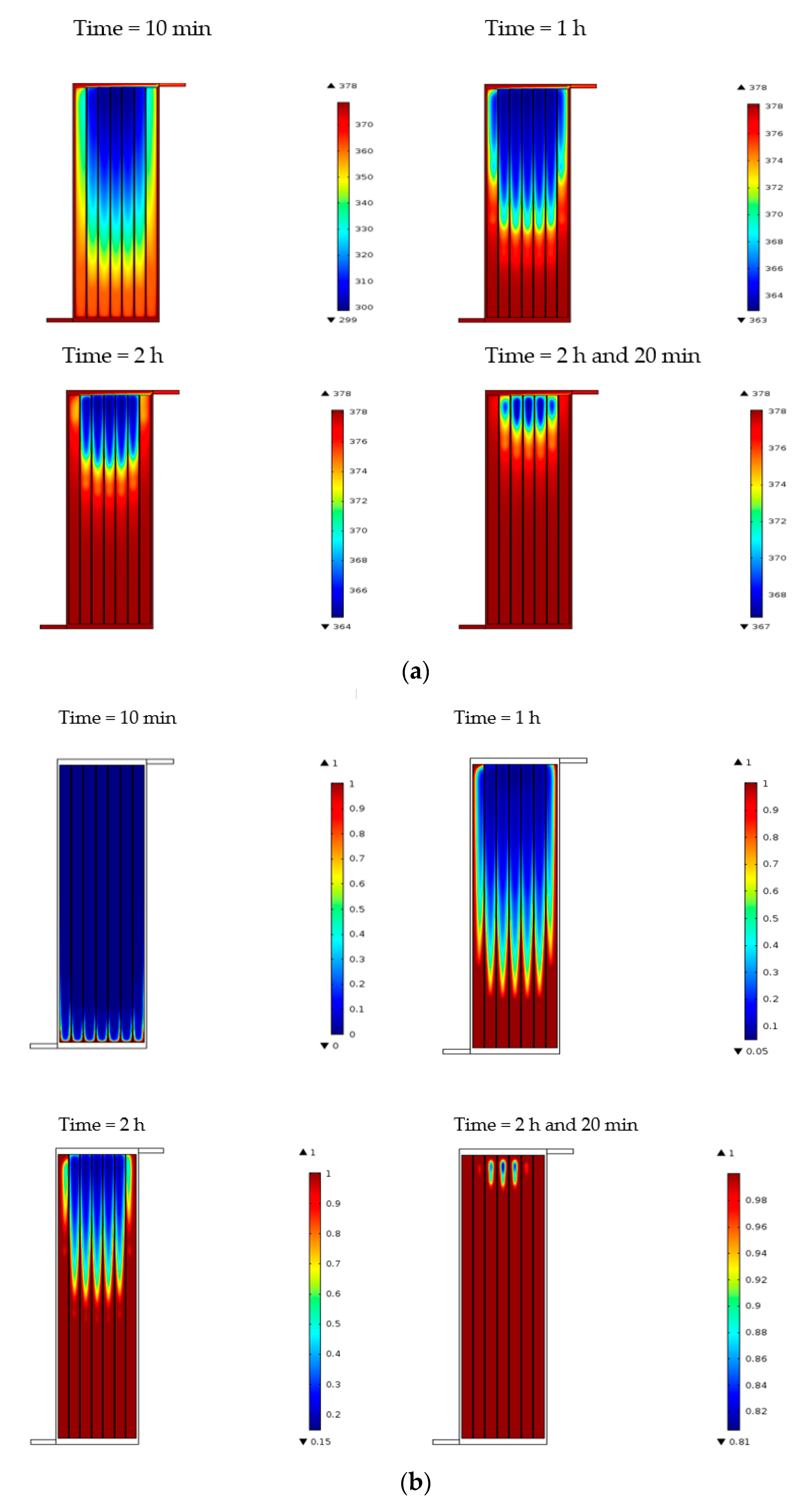
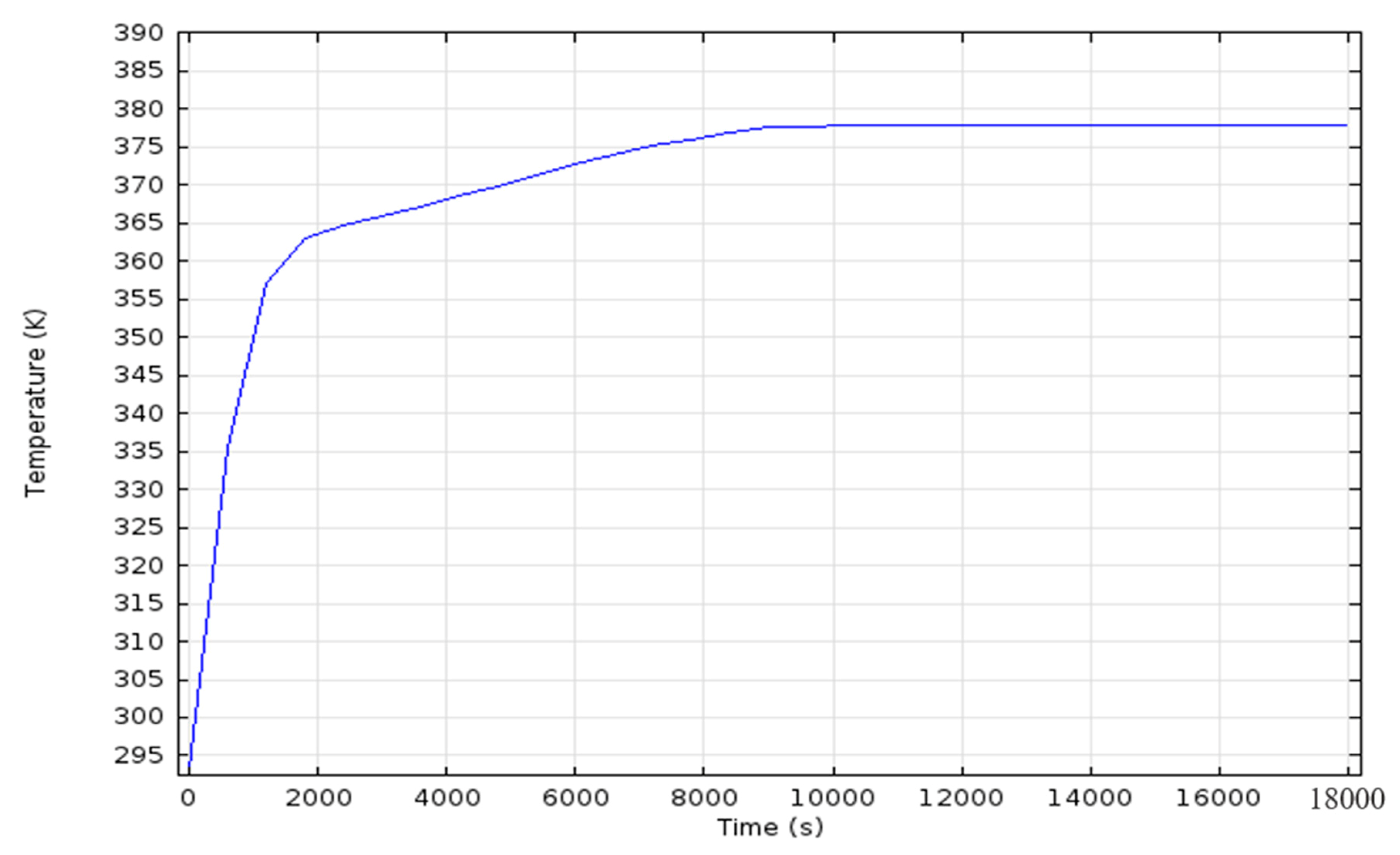
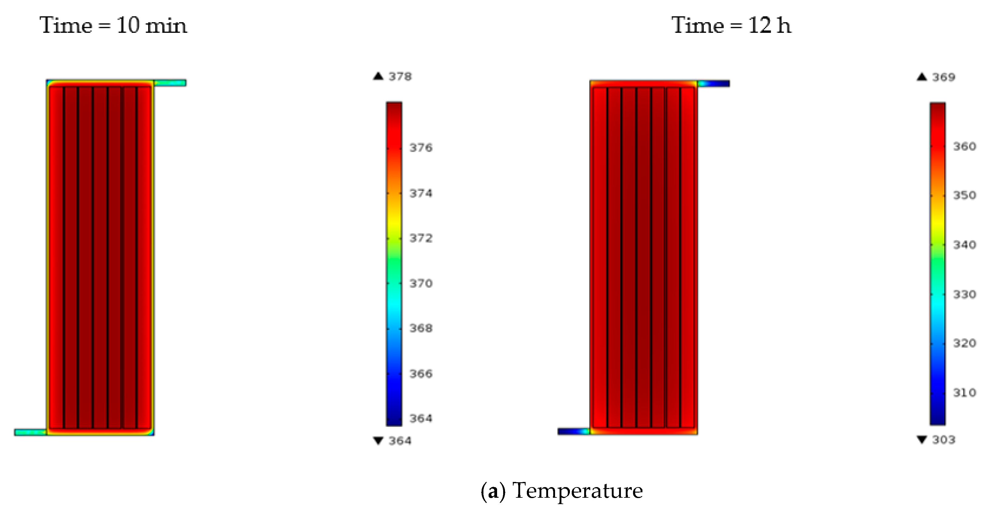
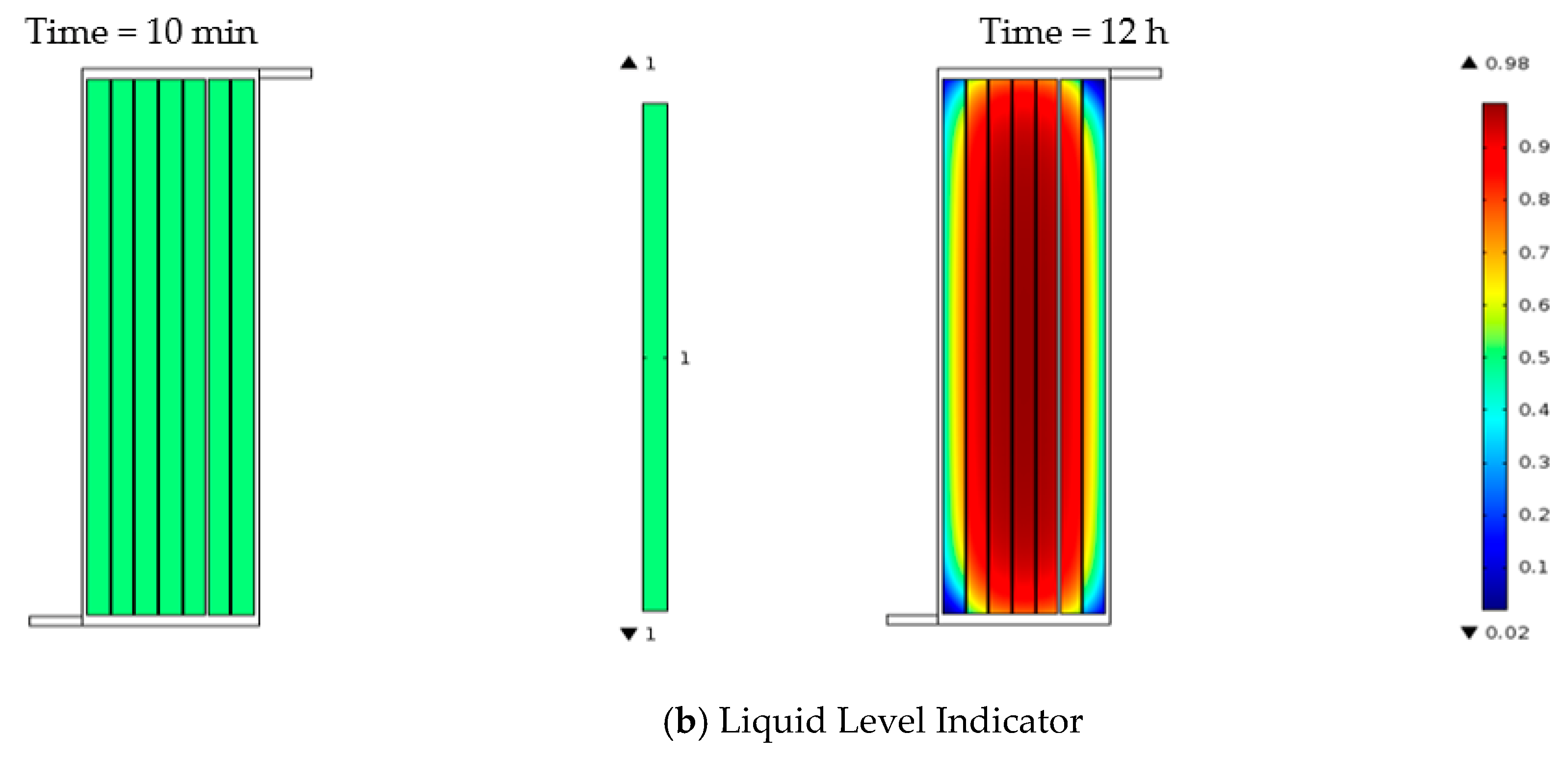
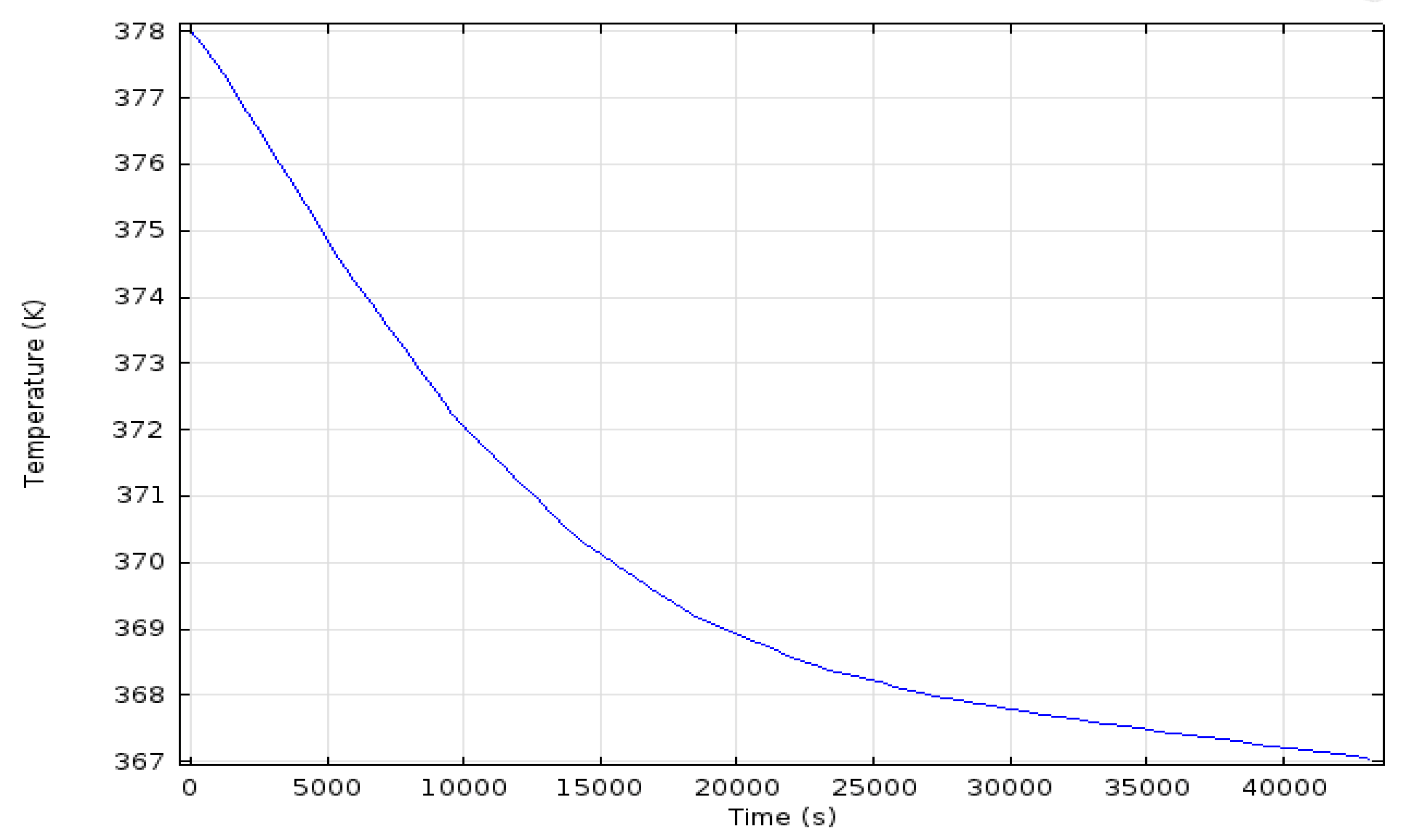
3. Simulation Results

For charging time simulation, laminar flow is considered, incorporating gravitational effects and insulation effects on the walls of the storage tank. At the inlet, the HTF flows with a velocity of 0.1 m/s normal to the inlet boundary. Temperature boundary condition is specified as 105 °C (378 K). In the simulation, it has been assumed that the temperature of the HTF has reached the maximum value of 105 °C. The outflow boundary condition was specified at the outlet. After 5 h of simulation time for HTF flow in the storage tank, the results are observed. Figure 2a,b illustrate the temperature contour along with liquid level indicator plots for charging the storage tank at various time steps.
The liquid level indicator shows how much portion of the PCM is converted into liquid so a scale of 0 to 1 is defined where 0 stands for the PCM to be solid while 1 stands for the liquid state. Any value between 0 and 1 is partially liquid and partially solid state of the PCM.
From the temperature contours it is observed that, once the HTF reaches a temperature of 105 °C (378 K) it takes about 140 min to completely melt the PCM as shown in the last contour in Figure 2. It is also observed that the liquid level indicator shows a small portion of the PCM which isn’t fully melted while the temperature contour shows that the temperature is nearly uniform at 104 °C (377 K) everywhere in the tube except the small solid PCM region. Figure 3 shows the relation of average temperature in the PCM region with respect to time showing the melting behavior of the PCM.

Simulation for Charging Time

Using the same geometry as Figure 1 for our storage time simulation, it is considered that the PCM was already melted and is at a temperature of 105 °C (378 K). The inlet and outlet boundary conditions are replaced by walls because during storage the valves will be closed so fluid will not flow. Convective heat flux condition is given to the outside boundary of the storage tank with ambient air temperature taken to be 20 °C (293 K). After 12 h of simulation time for airflow over the charged storage tank the results are observed. Figure 4 illustrates the temperature contour along with liquid level indicator plots for storing heat in the storage tank for various time steps.
As it can be observed that, it takes about 12 h to re-solidify the PCM up to some extent. The storing capacity for 8 cm thick insulation is very high. The temperature plot for storage time is shown in Figure 5.

4. Fabrication

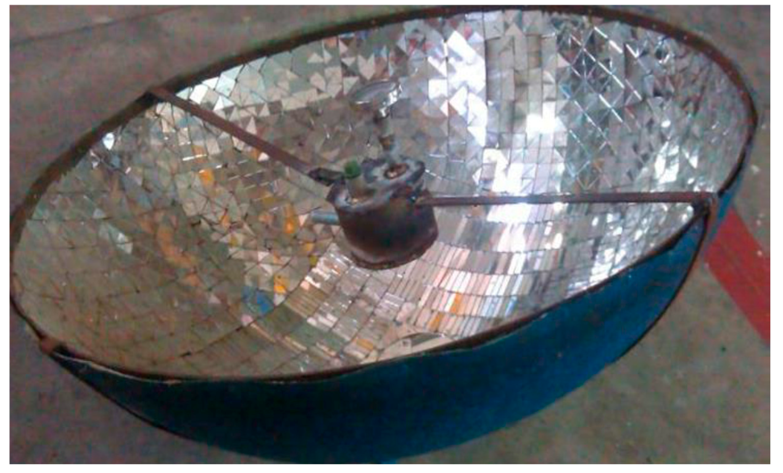
4.1. Prototype Modeling of Solar Concentrator

The prototype design was carried out with CAD/CAM software Creo parametric, which contemplates the parabola and focus characteristics, as well as the dimensions adjusted to the estimated size from the above calculations. As shown in Figure 6, the parabolic concentrator support has four support points; each support point has a piece to level the structure to the surface. There are four wheels attached to these four support points. The parabolic dish concentrator can rotate only in one axis with the help of screws. The whole structure (stand dish assembly) can be rotated in the other axis with the help of the support wheels

4.2. Design of Solar Concentrator
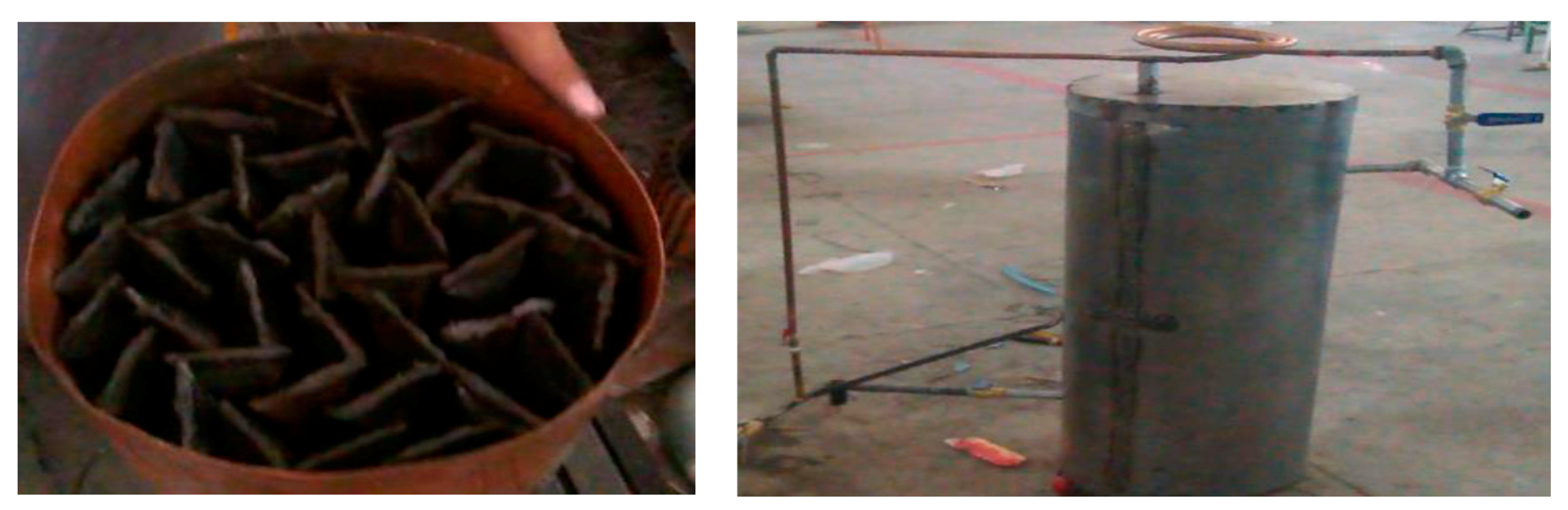
The parabolic dish is made up of fiber glass and small pieces of mirror are attached to the inner surface of the concentrator, which reflects the solar radiation at a single point known as the focal point. At the focal point, the receiver tank is placed which contains the heat transfer fluid which is heated up through the sunlight directed toward it. This heat transfer fluid is moved from receiver tank to the storage tank with the help of pump until the PCM is melted. Figure 7 shows the solar concentrator that was manufactured and utilized in this study.

4.3. PCM Tubes

Steel tubes are used for encapsulating the PCM. These PCM tubes are filled by melted PCM and welded from both sides as shown in Figure 8. The dimensional aspect of the PCM tubes has already been summarized in Table 1.

4.4. Storage Tank

The storage tank consists of two cylindrical tanks made of steel as shown in Figure 9. The internal tank also known as PCM tank contains the PCM tubes while the other tank is used as an external tank. There is styrofoam and glass wool insulation between the internal tank and external tanks.

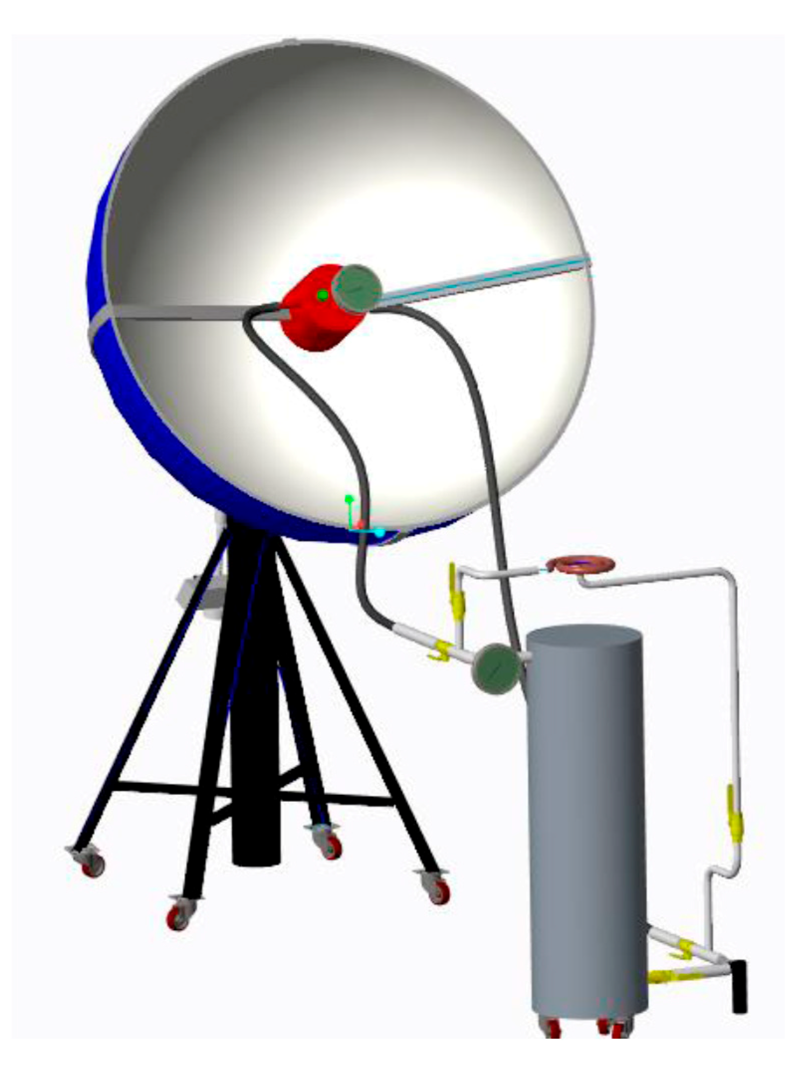
4.5. Assembled Design

Flexible rubber pipes are used to assemble the receiver tank and storage tank, so that the concentrator can rotate freely on two axes. A copper coil which utilizes the stored energy is connected to storage tank by steel pipes. In order to circulate the HTF in the system, a 12 Volt pump of the type originally used to spray water on the windshield in cars is used. Five ball valves are used to direct the flow of the HTF into the two thermal circuits. Two dial temperature sensors are attached to the receiver tank and at outlet of the storage tank to measure the temperature in the respective tanks. The flow chart of charging and discharging of the PCM is shown in Figure 10a,b, respectively. Figure 11 shows the design of the assembled solar energy storage system

5. Experimental Results and Discussion

In this section, the experimental results for the solar thermal energy storage system based upon the assembled experimental setup are discussed. The experimental results are compared and discussed with simulated results.

5.1. Experimental Results

Figure 12 shows the temperature behavior of the HTF. The following results were obtained for charging the PCM storage tank.
The results show a linear trend as the temperature of the HTF follows a linear pattern as time advances and reaches a value of 98 °C. At this point, the temperature of the HTF approaches closer to its boiling point, i.e., 104.4 °C, so the process is halted for a while to regain the temperature of 98 °C. The temperature is maintained by this process for about 2 h and 50 min in order to completely melt the PCM.
Figure 13 shows the results for the storing time of the solar thermal energy storage system. The charged storage tank was left in the open air after sunset and the recorded temperature relation with respect to time is given as follows.
Figure 14 shows that initially the temperature of the PCM at 98 °C steadily decreases to 92 °C and then remains constant for about 3 h at said temperature. The temperature remains constant at this value due to the latent heat of the PCM being released at 92 °C and then the temperature steadily decreases to about 81 °C after 7 h. This means that the solar thermal energy storage system has the capacity to store energy for about 7 h after sunset. The discharge time of the system was found from another experiment by first charging the storage tank at 97 °C and then storing the energy for about 1 h, and then by putting water in a pot placed above the heating coil.
Figure 14 shows that the stored energy can be utilized for 40 min before discharging the system completely as the temperature falls below 70 °C after this time and the remaining available heat energy is not enough for cooking.

5.2. Analysis and Discussion

The comparison of the experimental and simulation results highlights that both the results are in conformance for the charging duration of the analysis but differ slightly when it comes to storage analysis. The difference in the results occurs because of the manufacturing defects with the insulation of the storage tank as the storage tank was not tightly insulated. This defect results in a significant heat loss affecting the storage capacity of the storage tank to reduce to 7 h as compared to 12 h as derived from the simulation results. However the experimentally measured charging time (2.83 h) is within reasonable error (5%) of the simulated charging time (2.66 h). From the results, it was analyzed that the discharging time of 40 min is reasonable to green vegetables and some pulses.

6. Conclusions

This paper presented an assessment of the design and fabrication of a thermal energy storage system using potash alum as a phase change material. Our preference of potash alum as a phase changing material over other materials is due to its easy availability at a lower price along with better thermal energy storage compatibilities for low temperature cooking and heating purposes. The prime importance for thermal energy storage performance is the coupling between the heat transfer fluid characteristics and storage performance. In this study, a mixture of ethylene glycol and water is used as heat transfer fluid. The experimental setup was developed and the results were compared with the simulation results performed in COMSOL. The propsed setup shows that thermal energy can be stored for up to 7 h at a maximum temperatue of 92 °C and minimum temperature of 81 °C after sunset, which is a very beneficial output of the proposed system. The simulation results were consistent with experimental results and confirm that the proposed thermal energy storage system could be successfully used efficiently for cooking and heating purposes for applications which require temperatures of less than 92 °C. i.e., low temperature cooking and water heating can be done using this setup. The application of this system is not limited to indoor cooking, and it can be used for several other applications requiring temperatures below 92 °C, for example, it can be used for heating water for indoor applications and also used as an indoor heater, etc.
As future work we can mention the following aspects: (1) We used two temperature sensors in the system, but no pressure sensor to measure the pressure in the system. The system should have a feedback loop from the pressure and temperature sensor to stop the pump from pumping the high temperature HTF; (2) The selection of the HTF can be improved; (3) The insulation of the tank can be improved by using a good manufacturing process and materials to enhance the storage capacity of the storage tank; (4) Simulation of discharging can be added by linking in to the already stored energy in the concentrator to an application; (5) The charging simulation can be improved to incorporate even more multiphysics and (6) a better concentrator design which can be linked to the phase change simulation of the concentrator discussed in this paper can be implemented. For example sunlight incidence upon a concentrator can be simulated using particle ray tracing simulation and concentrated upon a receiver tank containing a HTF which heats up. A pump can be added from the receiver to the concentrator and back to the receiver to complete the loop Design improvements can be further achieved by using different variables for various parameters in the simulation and the optimized results can be found based upon the best results for charging, storing and discharging times. A few improvements in the design of the concentrator and storage tank could yield a commercially viable product.

Author Contributions

M.S.M. and N.I., Conceptualization, invistgation, methodology, writing draft, validation Data curation, formal analysis. A.W. & S.K. writing review, investagation, funding acquisition, supervision, review and editing. M.O.K. and M.U.A. investagation, review and editing, resources, editing, validation. T.K. and K.-C.K., funding acquisition, resources. Z.R., experimental anaysis, revised the draft, investigation and S.T.u.I.R. investigate, review & Editing & experimental anaysis. All authors have read and agreed to the published version of the manuscript.

Funding

This work was supported by the Basic Science Research program through the National Research Foundation of Korea (NRF) and funded by the Ministry of Education under grant NRF-2019R1D1A1A09058357.

Conflicts of Interest

The authors declare no conflict of interest.

References

  1. Li, M.-J.; Tao, W.-Q. Review of methodologies and polices for evaluation of energy efficiency in high energy-consuming industry. Appl. Energy 2017, 187, 203–215. [Google Scholar] [CrossRef]
  2. Ascione, F. Energy conservation and renewable technologies for buildings to face the impact of the climate change and minimize the use of cooling. Sol. Energy 2017, 154, 34–100. [Google Scholar] [CrossRef]
  3. Kittner, N.; Lill, F.; Kammen, D.M. Energy storage deployment and innovation for the clean energy transition. Nat. Energy 2017, 2, 17125. [Google Scholar] [CrossRef]
  4. Prasad, A.A.; Taylor, R.A.; Kay, M. Assessment of solar and wind resource synergy in Australia. Appl. Energy 2017, 190, 354–367. [Google Scholar] [CrossRef]
  5. Li, Q.; Liu, Y.; Guo, S.; Zhou, H. Solar energy storage in the rechargeable batteries. Nano Today 2017, 16, 46–60. [Google Scholar] [CrossRef]
  6. Nazir, H.; Batool, M.; Osorio, F.J.B.; Isaza-Ruiz, M.; Xu, X.; Vignarooban, K.; Phelan, P.; Kannan, A.M. Recent developments in phase change materials for energy storage applications: A review. Int. J. Heat Mass Transf. 2019, 129, 491–523. [Google Scholar] [CrossRef]
  7. Pelay, U.; Luo, L.; Fan, Y.; Stitou, D.; Rood, M. Thermal energy storage systems for concentrated solar power plants. Renew. Sustain. Energy Rev. 2017, 79, 82–100. [Google Scholar] [CrossRef]
  8. Esteves, L.; Magalhães, A.; Ferreira, V.M.; Pinho, C. Test of Two Phase Change Materials for Thermal Energy Storage: Determination of the Global Heat Transfer Coefficient. ChemEngineering 2018, 2, 10. [Google Scholar] [CrossRef] [Green Version]
  9. Zeinelabdein, R.; Omer, S.; Gan, G. Critical review of latent heat storage systems for free cooling in buildings. Renew. Sustain. Energy Rev. 2018, 82, 2843–2868. [Google Scholar] [CrossRef]
  10. Patankar, S. Numerical Heat Transfer and Fluid Flow; CRC Press: Boca Raton, FL, USA, 2018. [Google Scholar]
  11. González-Roubaud, E.; Pérez-Osorio, D.; Prieto, C. Review of commercial thermal energy storage in concentrated solar power plants: Steam vs. molten salts. Renew. Sustain. Energy Rev. 2017, 80, 133–148. [Google Scholar] [CrossRef]
  12. Alva, G.; Liu, L.; Huang, X.; Fang, G. Thermal energy storage materials and systems for solar energy applications. Renew. Sustain. Energy Rev. 2017, 68, 693–706. [Google Scholar] [CrossRef]
  13. Zhang, P.; Meng, Z.; Zhu, H.; Wang, Y.L.; Peng, S. Melting heat transfer characteristics of a composite phase change material fabricated by paraffin and metal foam. Appl. Energy 2017, 185, 1971–1983. [Google Scholar] [CrossRef] [Green Version]
  14. Amin, M.; Putra, N.; Kosasih, E.A.; Prawiro, E.; Luanto, R.A.; Mahlia, T. Thermal properties of beeswax/graphene phase change material as energy storage for building applications. Appl. Therm. Eng. 2017, 112, 273–280. [Google Scholar] [CrossRef]
  15. Karaipekli, A.; Biçer, A.; Sari, A.; Tyagi, V.V. Thermal characteristics of expanded perlite/paraffin composite phase change material with enhanced thermal conductivity using carbon nanotubes. Energy Convers. Manag. 2017, 134, 373–381. [Google Scholar] [CrossRef]
  16. Zeng, J.-L.; Cao, Z.; Yang, D.W.; Sun, L.-X.; Zhang, L. Thermal conductivity enhancement of Ag nanowires on an organic phase change material. J. Therm. Anal. Calorim. 2009, 101, 385–389. [Google Scholar] [CrossRef]
  17. Shukla, A.; Buddhi, D.; Sawhney, R. Thermal cycling test of few selected inorganic and organic phase change materials. Renew. Energy 2008, 33, 2606–2614. [Google Scholar] [CrossRef]
  18. Singh, R.; Sadeghi, S.; Shabani, B. Thermal Conductivity Enhancement of Phase Change Materials for Low-Temperature Thermal Energy Storage Applications. Energies 2018, 12, 75. [Google Scholar] [CrossRef] [Green Version]
  19. Bushnell, D.L. Performance studies of a solar energy storing heat exchanger. Sol. Energy 1988, 41, 503–512. [Google Scholar] [CrossRef]
  20. Sharma, S.; Buddhi, D.; Sawhney, R.; Sharma, A. Design, development and performance evaluation of a latent heat storage unit for evening cooking in a solar cooker. Energy Convers. Manag. 2000, 41, 1497–1508. [Google Scholar] [CrossRef]
  21. Buddhi, D.; Sharma, S.; Sharma, A. Thermal performance evaluation of a latent heat storage unit for late evening cooking in a solar cooker having three reflectors. Energy Convers. Manag. 2003, 44, 809–817. [Google Scholar] [CrossRef]
  22. Schmerse, E.; Ikutegbe, C.A.; Auckaili, A.; Farid, M.M. Using PCM in Two Proposed Residential Buildings in Christchurch, New Zealand. Energies 2020, 13, 6025. [Google Scholar] [CrossRef]
  23. Nemś, A.; Puertas, A.M. Model for the Discharging of a Dual PCM Heat Storage Tank and its Experimental Validation. Energies 2020, 13, 5687. [Google Scholar] [CrossRef]
  24. Leang, E.; Tittelein, P.; Zalewski, L.; Lassue, S. Design Optimization of a Composite Solar Wall Integrating a PCM in a Individual House: Heating Demand and Thermal Comfort Considerations. Energies 2020, 13, 5640. [Google Scholar] [CrossRef]
  25. Pasupathi, M.K.; Alagar, K.; Mm, M.; Aritra, G. Characterization of Hybrid-nano/Paraffin Organic Phase Change Material for Thermal Energy Storage Applications in Solar Thermal Systems. Energies 2020, 13, 5079. [Google Scholar] [CrossRef]
  26. Wei, G.; Wang, G.; Xu, C.; Ju, X.; Xing, L.; Du, X.; Yang, Y. Selection principles and thermophysical properties of high temperature phase change materials for thermal energy storage: A review. Renew. Sustain. Energy Rev. 2018, 81, 1771–1786. [Google Scholar] [CrossRef]
  27. Qiu, S.; Solomon, L.; Fang, M. Study of Material Compatibility for a Thermal Energy Storage System with Phase Change Material. Energies 2018, 11, 572. [Google Scholar] [CrossRef] [Green Version]
  28. Palomba, V.; Brancato, V.; Palomba, G.; Borsacchi, S.; Forte, C.; Freni, A.; Frazzica, A. Latent Thermal Storage for Solar Cooling Applications: Materials Characterization and Numerical Optimization of Finned Storage Configurations. Heat Transf. Eng. 2018, 40, 1033–1048. [Google Scholar] [CrossRef]
  29. Prabhu, A.N.; Shetty, P.K.; Vali, I.; Kumar, H.; Udupa, S. Gamma and neutron irradiation effects on the structural and optical properties of potash alum crystals. Nucl. Instrum. Methods Phys. Res. Sect. B Beam Interact. Mater. Atoms 2017, 413, 37–41. [Google Scholar] [CrossRef]
  30. Benoit, H.; Spreafico, L.; Gauthier, D.J.; Flamant, G. Review of heat transfer fluids in tube-receivers used in concentrating solar thermal systems: Properties and heat transfer coefficients. Renew. Sustain. Energy Rev. 2016, 55, 298–315. [Google Scholar] [CrossRef]
  31. Lorenzin, N.; Abánades, A. A review on the application of liquid metals as heat transfer fluid in Concentrated Solar Power technologies. Int. J. Hydrog. Energy 2016, 41, 6990–6995. [Google Scholar] [CrossRef]
  32. Li, H.; He, Y.; Hu, Y.; Jiang, B.; Huang, Y. Thermophysical and natural convection characteristics of ethylene glycol and water mixture based ZnO nanofluids. Int. J. Heat Mass Transf. 2015, 91, 385–389. [Google Scholar] [CrossRef]
Figure 1. Energy storage tank modeling in COMSOL.
Energies 13 06169 g001
Figure 2. (a) Temperature for 10 min, 1 h, 2 h and 2 h and 20 min; (b) Liquid level temperature for 10 min, 1 h, 2 h and 2 h and 20 min.
Energies 13 06169 g002
Figure 3. Temperature vs. Time of melting of the PCM.
Energies 13 06169 g003
Figure 4. Storage time by: (a) temperature and (b) liquid level for 10 min and 12 h.
Energies 13 06169 g004aEnergies 13 06169 g004b
Figure 5. Temperature vs. storage time to resolidify the PCM.
Energies 13 06169 g005
Figure 6. CAD/CAM Model of the solar concentrator.
Energies 13 06169 g006
Figure 7. Manufactured solar concentrator.
Energies 13 06169 g007
Figure 8. PCM steel tubes used for encapsulating the PCM.
Energies 13 06169 g008
Figure 9. Fabrication of the storage tank.
Energies 13 06169 g009
Figure 10. (a) Flow chart of charging PCM; (b) Flow chart of discharging PCM.
Energies 13 06169 g010aEnergies 13 06169 g010b
Figure 11. Completely assembled prototype of the solar thermal energy storage system.
Energies 13 06169 g011
Figure 12. Plot of HTF temperature vs charging time.
Energies 13 06169 g012
Figure 13. Plot of temperature vs. storage time.
Energies 13 06169 g013
Figure 14. Plot of temperature vs. discharge time after 1 h.
Energies 13 06169 g014
Table 1. Design requirement for cooking.
S. NoDescription, Symbol (Units)Values
1Temperature requirement, T (°C)95–97
2Cooking time, t (minutes)55
3Power of electric Heater, Ph (W)1000
4Required heat, Q (kJ)3300
5Heat losses, Ql (kJ)100
6Total Heat, QT (kJ)3400
7Steel pipe inner diameter (inches)1
8Steel pipe length (inches)30
Table 2. Properties of Phase Change Materials [26,27].
Thermal PropertiesPhysical PropertiesKinetic PropertiesChemical PropertiesEconomics
Suitable phase-transition temperatureFavorable phase equilibriumNo super coolingLong-term chemical stabilityAbundant
High latent heat of transitionHigh densitySufficient crystallization rateCompatibility with materials of constructionAvailable
Good heat transferSmall volume change No toxicityCost effective
Low vapor pressure No fire hazard
Table 3. Design parameters of the storage tank, PCM and HTF.
S.NoDescription, Symbol (Units)Values
1Heat of fusion of potash alum (PCM), hm (kJ/kg)184
2Required mass of potash alum (PCM), mpcm (kg)18.4
3Specific heat of potash alum in the liquid phase (melted), Clp (kJ/kg.K)2.76
4Specific heat of potash alum in liquid phase, Csp (kJ/kg.K)1.38
5Melted fraction, am1
6Melting point of potash alum, Tm (°C)92
7Initial temperature, Ti (°C)10
8Final temperature, Tf (°C)140
9Total heat storage capacity, Qpcm (kJ)4591
10Density of potash alum in the liquid phase (melted), ρi (kg/m3)1300
11Volume of potash alum, V (m3)0.0079
12Outer diameter of cylinder, doo (m)0.201
13Inner diameter of cylinder, dii (m)0.2
14Inner diameter of tube, dit (m)0.0254
15Number of tubes, n89
16Length of PCM tube, Lpcmt (m)0.74
17Length of storage tank, Lst (m)0.77
18Inner radius of storage tank inlet, rii (m)0.00635
19Inner inlet area, Ai (m2)0.000125
20Volume flow rate, q` (m3/s)1.235 × 10−5
21Mass flow rate, m` (kg/s)0.013
22Velocity of HTF at the inlet, u (m/s)0.1
23Viscosity of HTF (at 20 °C), µhtf (Pa.S)2.1671 × 10⁻³
24Reynold’s number, Re605
25Required flow rate of pump, (m3/s)2.5 × 10−5
Publisher’s Note: MDPI stays neutral with regard to jurisdictional claims in published maps and institutional affiliations.

