Abstract
This manuscript presents a robust tracking (servomechanism) controller for linear time-invariant (LTI) islanded (autonomous, isolated) microgrid voltage control. The studied microgrid (MG) consists of many distributed energy resources (DERs) units, each using a voltage-sourced converter (VSC) for the interface. The optimal tracker design uses the ellipsoidal approximation to the invariant sets. The MG system is decomposed into different subsystems (DERs). Each subsystem is affected by the rest of the system that is considered as a disturbance to be rejected by the controller. The proposed tracker (state feedback integral control) rejects bounded external disturbances by minimizing the invariant ellipsoids of the MG dynamics. A condition to design decentralized controllers is derived in the form of linear matrix inequalities. The proposed controller is characterized by rapid transient response, and zero error in the steady state. A robustness analysis of the control strategy (against load changes, load unbalances, etc.) is carried out. A MATLAB/SimPowerSystems (R2017b, MathWorks, Natick, MA, USA) simulation of the case study confirm the robustness of the proposed controller.
1. Introduction
Distributed energy resources (DERs), such as photovoltaic arrays (PVs) and wind, are now connected to the power grids to address environmental issues and emissions of global warming gas [1]. The loads represented by constant impedances are connected to DGs [2,3,4,5,6,7,8,9,10,11,12,13,14] for the operation of MG at the distribution networks. Stability analysis is one of the most critical issues for inverter-interfaced MG [4,5,6,7,8]. Attaining precise power-sharing while controlling the voltage magnitude and frequency in an autonomous MG is the main DERs control objective [4]. Researchers have used various centralized and decentralized control strategies to improve MG dynamic performance [8,9,10,11,12]. The benefits and drawbacks of the schemes are summarized in [8]. In [8,9], different centralized control schemes are proposed to control multiple parallel inverters, maximize the DERs output power, and optimize the power exchange between the MG and the main grid. Centralized control in remote areas with a long distance between inverters is impractical and expensive due to the requirement of building a reliable communication link [9]. To avoid the utilization of expensive communication networks, decentralized systems are utilized [10,11]. Distributed control that lies in between the centralized and decentralized approaches in terms of complexity, price, and effectiveness [12,13,14,15]. It allows communication between the subsystems. However, it faces the problems of packet loss, communication delay, and quantization errors.
MGs can operate either connected to the utility main grid or isolated form it. The MG operates in islanded mode when it is disconnected from the grid and continues to provide power to local loads. The voltage and frequency are no longer dictated by the grid, and they can have values dictated by the MG’s DER units. Because of the load variations and the DERs’ output power intermittency, an islanded MG may encounter problems of reliability, robustness and power quality. Novel optimal and robust control strategies are required to minimize these problems.
Voltage source converters (VSC) are widely utilized to interface the MG to the grid. VSCs perform power flow conversion and control. Several control strategies for the autonomous operation of VSC-based DER units are suggested. The frequency/power and voltage/reactive-power droop control [16] are among the most widely used control techniques. Considering an active load to the autonomous MG is given in [17]. A control strategy is proposed in [18] which ensures robust stability despite parametric uncertainties due to load variations using Kharitonov’s theorem. Reference [18] does not consider neither multi-DG micro-grids nor decentralized control. This strategy is based on a low order proportional integral controller, which only uses its d-axis part in dq-frame to regulate the load voltage. A more robust control strategy is suggested in [19,20], using a servomechanism controller. Nevertheless, this is a high-order controller that is more complex than the one in [18]. Note that [19] considers only a single-DG islanded system. The decentralized control in [20] has higher dynamics than the proposed one in this manuscript.
This paper presents the decentralized control for each DER. The suggested controller uses only its local information. Decentralization is tackled by decomposing the global MG system into subsystems (DERs). The dynamic effect of the rest of the system on a particular DER is considered as an external disturbance. The proposed controller has to achieve fast response + zero steady state error in addition to rejecting the external disturbance. Note that the designer faces two challenges: (1) a modeling problem and (2) a control problem. The designer has to obtain the model for the global large system. The resulting centralized controller will be of large dimension, difficult to implement. In this case, the designer needs to adopt model reduction or decentralized control. This paper adopts decentralized control for each subsystem, for each only the local (subsystem) states are used.
The designed controllers are decentralized in the sense that it uses only the local information of its subsystem. Centralized versus decentralized control can be summarized as follows. The benefit of using decentralized control via local subsystem information is avoiding using a hub computer (controller) whose failure will cause loss of the global system stability. It also avoids a costly communication network (and its associated delay, packet loss) to transmit information of the whole system to the centralized controller. This is in addition to the high dimensionality of centralized control.
One of the key issues in the control theory is the rejection of external disturbance. It is studied by both the linear quadratic Gaussian optimization (where the disturbance is assumed to be random) and the H∞-optimization (where the disturbance is considered as arbitrary bounded). An alternative approach to disturbance rejection relying on the method of invariant sets and invariant ellipsoids is proposed in [21,22]. The invariant ellipsoid method is a newly born powerful method in robust control theory.
The present work formulates the problem of external disturbances (arbitrary bounded) rejection in terms of the invariant ellipsoids. The proposed feedback+ integral controller is designed by minimizing the size of the invariant ellipsoids of the dynamic system. The controller synthesis is formulated using linear matrix inequalities (LMIs) that can be effectively solved using convex optimization techniques.
The main contributions of this paper are summarized as follows:
- An effective decentralized control is developed. The overall system is decomposed into subsystems, for each a local controller is installed. Each controller is designed to achieve fast response, zero steady-state error, and effective rejection of external disturbances that are caused by the different subsystems.
- A new method, based on LMIs and invariant sets, is proposed to design an optimal tracking controller that effectively rejects external disturbances.
The rest of this paper is organized as follows. Section 2 describes the MG under investigation and the proposed control strategy. The MG mathematical model is provided in Section 3. Section 4 details the controller synthesis that is based on the ellipsoidal design. Verification of the performance and viability of the proposed method, based on a simulation case study. Conclusions are stated in Section 5.
Notations and Facts
Rm is the set of m × 1 vectors, Rrxq is the set of real matrices of dimension r × q, and (.)′ denotes the transpose of a vector or a matrix. For a matrix P, P > 0 (< 0) means that P is a symmetric positive (negative) definite matrix. Also, the shorthand means . Similarly, (M + N + *) means (M + N + M’ + N’). Matrices are denoted by capital letters, vectors are denoted by small letters, and scalers are denoted by small Greek letters. Finally, 0 and I denote the zero matrices and the identity matrix, respectively.
Fact 1: The time varying uncertainty ∆(t) can be removed using the fact
Fact 2: (Schur complements). Given a matrix M composed of
where then M > 0 if and only if
Fact 2 is used to linearize a special class of nonlinear matrix inequalities.
2. Microgrid Study System
2.1. Microgrid Description
The MG under study is shown in Figure 1a. A control strategy and power management system (PMS) for several-distributed energy resources (DER) islanded microgrids is proposed in [20]. DERs can also be viewed as distributed generators (DGs). In this system, the PMS defines the voltage set points at the DER terminals and communicates them (via a low bandwidth communication medium) to the local controllers (LCs) of DER units. The DER terminal voltages are robustly regulated by the LCs in a decentralized manner. The MG frequency is controlled using an open-loop control scheme using the DER units’ internal crystal oscillators. To ensure the same frequency, these oscillators are synchronized by a common timing signal received from a global positioning system (GPS), Figure 1b.
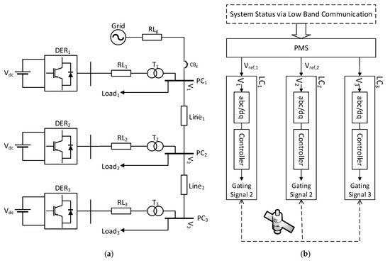
Figure 1.
Case-study system (a) The studied microgrid (MG) and (b) power management system (PMS) and non-droop control system.
The MG has of three DER units rated at 0.6 kV. Their power ratings are 1.6, 1.2, and 0.8 MVA. The DER units represent photovoltaic PV generating stations. Each DER unit is modelled using a 1.5 kV DC voltage source, a voltage sourced converter (VSC), and a series RL filter. A 0.6 kV/13.8 kV step-up transformer is used to interface each DER to the grid at its corresponding point of coupling (PC) bus. The three busses in Figure 1b has their local loads and they are connected using two sections of the 13.8 kV distribution line. The utility grid is described by an AC voltage source behind series R and L elements. The MG can be operated in grid-connected or islanded mode based on the circuit breaker CBg status. The parameters of the study system are given in Table 1.

Table 1.
Parameters of the microgrid.
In a low-voltage distribution system, the values line parameters are difficult to acquire, especially when the devices are installed in an ad hoc manner by individual users. Reference [23] proposes a novel method for automated impedance estimation based on practically available parameters at the terminal nodes.
2.2. Mathematical Model of The Microgrid
To design robust linear controllers, a linearized model of the microgrid of Figure 1a using a synchronously rotating dq-frame, which is based on the fundamental frequency of the system, is required. The linearized state space model of the MG is derived based on the single-line diagram shown in Figure 2. Each DER unit is described by a three-phase voltage source inverter with a series RL branch. Loads are represented by an equivalent parallel RLC circuit. Distribution lines are modeled using lumped series RL elements.
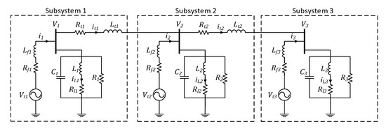
Figure 2.
Single-line diagram of the microgrid.
The MG in Figure 2 is partitioned into three subsystems. Subsystem 1 model, in the abc reference frame, is
where is a 3 × 1 vector. The coefficients of differential Equation (1) are time varying, difficult to handle. To simplify the controller design, the abc frame of system (1) is transformed to the dq frame using Park’s transformation. This results in differential equations with constant coefficients, easy to work with. Assuming a three-wire system and using the Park’s transformation in Equation (3), the mathematical model (1) can be rewritten in a synchronously rotating dq-frame. In Equation (3),
is the phase angle and w is the angular frequency of the crystal oscillator internal to DER. The resulting state equation in the dq frame is given in Equation (4).
Likewise, the subsystems 2, and 3 dq-models are both derived and used to write the overall system’s state-space model
where
3. Decentralized Tracking Control
In control system design, the output has to follow the input. If the input is constant, the control problem is termed as a regulator problem. If the input is time varying, it is called a servomechanism (tracking) problem. A decentralized servomechanism controller for the system (5) is designed in this section. System (5) represents an interconnected composite system composed of three subsystems. Each subsystem can be controlled by using only local controllers about each subsystem [3]. Splitting the matrix A = (Aij, i, j = 1, 2, 3) in Equation (5) into a two parts: diagonal, Ad, and off diagonal, D, one gets,
where
In Equation (6), the effect of interconnecting the rest of the system on a specific subsystem is considered to be an external disturbance, Dx, to be rejected by the controller proposed. The vector x is assumed to be an external bounded disturbance w.
The following structure is considered to implement a decentralized controller, consisting of three control agents, for the MG under study.
where
so that the augmented closed-loop system is described by
Note that the proposed controller (7–8) is a decentralized one equipped with an integral part to eliminate the steady state errors thus the desired reference voltage is tracked. The microgrid dynamics and the suggested control is modelled in Figure 3.
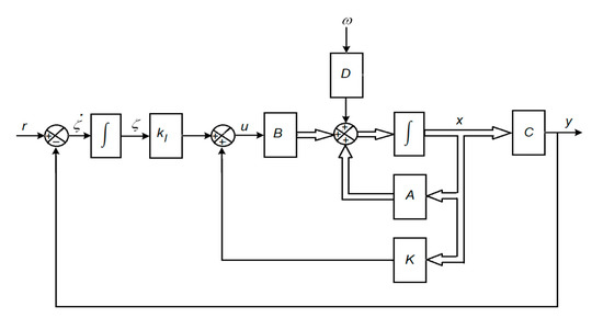
Figure 3.
Servo system.
The problem of MG voltage control is the design of a decentralized controller in which the output voltage tracks the reference voltage. The tracker must be robust against the load variations and must minimize the interconnection effect of the rest of the system on the output voltage of a particular subsystem. This is termed disturbance rejection control.
The proposed controller relies on using the invariant (or attracting as will be seen) ellipsoid’s concept. A summary is described as follows:
3.1. Attracting Ellipsoid
Consider a continuous-time state space model of a linear dynamical system:
where x(t) ∈ Rn is the system state vector, z(t) ∈ Rl is the system output to be optimized(minimized). It is assumed that the output for feedback y is equal to the output to be optimized, z. Hence C = Cz.
The external disturbances w(t) ∈ Rm are bounded i.e., subject to the constraint
For the vector (.), denotes the Euclidean norm of (.). The control target is to minimize the impact of disturbance Dw on the output z. The constraint (10) can be always satisfied by properly scaling the matrix D. The disturbances w(t) is considered to be L∞ bounded external disturbance. It is assumed that (9) is stable, the pair (A, D) is controllable, and that C has maximum-rank. The goal is to determine the system’s family of attracting ellipsoids.
An ellipsoid E with origin at the center can be written as
where P is a symmetric positive definite matrix called the matrix of the ellipsoid.
The ellipsoid E is termed state invariant if for any initial state x(0) lies inside E, the trajectory x(t) stays inside the ellipsoid for t > 0 for all admissible disturbances (10). When the initial state x(0) lies outside the ellipsoid, the trajectory x(t) is attracted to the ellipsoid for t > 0. This is achieved if the ellipsoid E represented a Lyapunov function
does not increase outside (including the boundary, ) of this ellipsoid, that is, if
Reference [22] shows that the ellipsoid E is invariant and attracting for system (8) if and only if
When the system is subjected to the family of bounded disturbance in Equation (10), the trajectories of the system relies inside the ellipsoid. To reduce the disturbance impact on the system states and outputs, the volume of the attracting ellipsoid must be minimized. Thus, an objective function must be formulated to represent ellipsoid volume.
In this paper, the trace function in Equation (15) is selected as the objective function. The tr(.) is defined as the sum of the diagonal elements of (.). It corresponds to the sum of the squares of the semi-axes of the state-invariant ellipsoid. The linearity of the trace function offers a significant advantage (the optimization problem becomes convex, easy to handle) compared to other functions that can be used to calculate the volume of the ellipsoid. With this choice, the optimization problem can be easily cast into a standard semi-definite program (SDP) (optimization of a linear function subject to LMI constraints) that can be easily solved using convex optimization solvers that are available using the MATLAB-LMI( R2017b, MathWorks, Natick, MA, USA) toolbox.
It is more important to minimize the disturbance impact on the controlled outputs z rather that the whole state vector x. This can be easily achieved by substituting the ellipsoid of Equation (11) by . Thus, if the attracting ellipsoid in Equation (10) bounds the x trajectory, then the output z is contained in the ellipsoid Ez. Minimizing the volume of Ez will minimize the MG voltage variations due to external disturbances.
The optimal state feedback controller design using attracting ellipsoids is discussed next.
3.2. Attracting Ellipsoid Design of State-Feedback Plus Integral Tracker
The state feedback regulator is discussed first. In this case, the reference is assumed to be constant. The main control objectives are to drive all the states and system outputs to the origin, ensure fast transient response and optimize the disturbance rejection performance. The results of this subsection are, then, extended to address a state feedback tracker where the reference is time varying.
Regulator Attracting Ellipsoid Design
Consider the linear system
where x ∈ Rn is the system state, z ∈ Rl is the controlled output, u ∈ Rp is the control signal, and w ∈ Rm is the external disturbance satisfying the constraint (10). The goal is to calculate the gain K of a linear proportional state feedback controller,
That guarantees stability of the closed-loop system and optimizes the disturbance rejection performance by minimizing the trace of the attracting output ellipsoid. It is worth noting that the inclusion of term B2u in Equation (16) prevents large values of control effort.
By substituting Equation (17) in Equation (16), the closed loop system is
The following theorem provides a semidefinite program formulation for the state feedback controller synthesis problem.
Theorem 1.
Let the external disturbances be L∞-bounded and the pair (A, B) controllable for the system (16). Then, the problem of designing a state feedback controller by state (17) that optimally rejects the external disturbance, in the sense of the trace that is output-attracting ellipsoid, is equivalent to
Minimize,
subject to the following constraints:
where Y = KP. The minimization is carried out with respect to the variables α, P = P’ ∈ Rn×n, Y ∈ Rp×n and Z = Z’ ∈ Rp×p [22].
Note that Equation (19) is nonlinear matrix equation (due to the product term ). If the scalar α > 0 is fixed, the optimization problem in Theorem 1 becomes convex which can be solved efficiently using convex optimization algorithms.
Theorem 1 does not consider a reference input in the regulator formulation. Thus, reference tracking cannot be achieved. In the next subsection, Theorem 1 is extended to offer both good dismissal of disturbance and good reference tracking.
3.3. Tracker Attracting Ellipsoid Design
It can be verified that the MG model (5) has no integrator (type 0 plant), and therefore, non-zero steady error will occur for step changes in the reference voltage. To ensure offset-free tracking of the voltage reference, the integrator must be inserted in the forward path of the loop. In a state feedback controller setup, the integrator is added as shown Figure 3 (which facilitates the Simulink modeling (R2017b, MathWorks, Natick, MA, USA).
From Figure 3, we obtain
Therefore, the augmented system is
or
where the augmented matrices are
The ellipsoidal design of regulators, theorem 1, can be generalized to the trackers design. The proposed controller has to be decentralized and robust against load variation (uncertainty) of the MG. For this, Equation (23) is modified to
The system time varying uncertainties have the norm-bounded form
The following theorem is developed.
Theorem 2.
Consider system in Equation (24) with the controllable pair (), and L∞-bounded external disturbances. Then, the decentralized robust state feedback with integral controller, which rejects optimally the external disturbances (in the sense of the trace that is output-invariant to the ellipsoid) is equivalent to minimizesubject to the following constraints:
where, and the minimization is carried out with respect to the variables,and ∈ Rp×p.
Proof of Theorem 2.
For the tracking problem, the matrices in Equation (19) are replaced by the augmented system matrices. Using Fact 2, the following can be obtained:
To cope with load variation (uncertainty) in the MG, is replaced with , and with in Equation (27). The resultant system is:
Substituting for the norm-bounded uncertainty in Equation (25), one gets
Separating the uncertainty terms, we obtain
Using Fact 1 to eliminate , Equation (28) is satisfied if the following matrix equation is satisfied:
Using Fact 2, theorem is proved. □
Decomposing global MG system into N-subsystems (DGs), the above theorem can be applied for each subsystem by adding a subscript i to every variable.
For ± 10% changes in load resistance, the norm-bounded uncertainty in Equation (25) for the subsystems DERS are shown in Table 2. Note that the load resistance does not appear in the off-diagonal matrices (the disturbance), hence the uncertainty matrices of the disturbance (25) F, and H = 0.

Table 2.
Norm-bounded uncertainties in .
The following optimal decentralized robust controller parameters are obtained by solving the LMIs of Theorem 2, with B2 selected as a unit matrix.
Decentralized robust tracker for DER1:
Decentralized robust tracker for DER2:
Decentralized robust tracker for DER3:
4. Simulation Results
The proposed control system performance is verified and tested using the MATLAB/SimPowerSystem Toolbox. The selected islanded PWM-inverter microgrid consisting of three-DGs as shown in Figure 2. It is implicit that each DG maintains a local load. The parameters of all DGs, transmission lines and local loads are presented in Table 1. In Figure 4, Figure 5, Figure 6, Figure 7, Figure 8 and Figure 9, the dynamic performance of the proposed designed controllers is assessed via several test scenarios, including voltage tracking, load change and load unbalance.
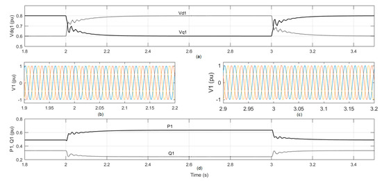
Figure 4.
Proposed controllers’ performance of DG 1 as a result of two-step changes in the voltages set point. (a) dq-components of the load voltage at point of coupling (PC) 1. (b,c) Instantaneous load voltages of PC 1. (d) Output active and reactive power of DG 1.
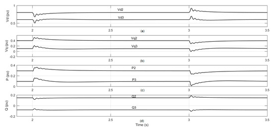
Figure 5.
Dynamic performances of DGs 2 and 3 as a result of two-step changes in Vdq1 set point. (a) d-component of the load voltages at PCs. (b) q-component of the load voltages at PCs. (c) Output active power of DGs. (d) Output reactive power of DGs.
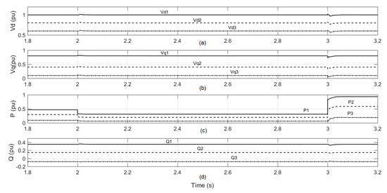
Figure 6.
Dynamic performances of DG 1, DG2, and DG 3 as a result of step changes in the load resistance in three-phase system. (a) d-component of the load voltages at three DGs. (b) q-component of the load voltages at three-DGs. (c) Output active power of three DGs. (d) Output reactive power of three DGs.
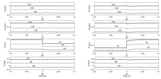
Figure 7.
Dynamic performances of DG 1, DG2, and DG 3 as a result of step changes in the load resistance in three-phase system. (a,b) d-component of the load voltages at three DGs. (c,d) q-component of the load voltages at three DGs. (e,f) Output active power of three DGs. (g,h) Output reactive power of three DGs.
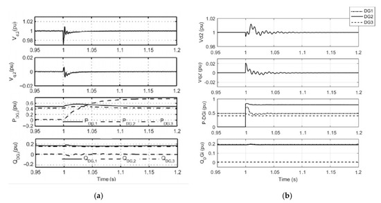
Figure 8.
Response for an increase in real power of load2. (a) Control of Reproduced from [20], the name of the publisher: IEEE Trans. Power Deliv [20] (b) Proposed control.
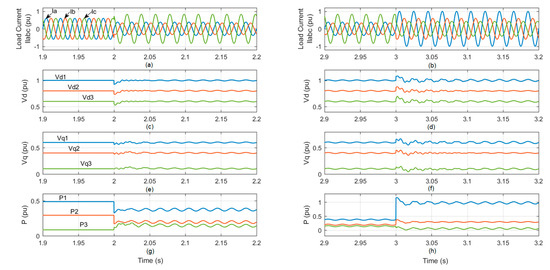
Figure 9.
Dynamic performances of DG 1, DG 2, and DG 3 during islanded micro-grid and unbalance load condition. (a) load currents, unbalance at t = 2 s, (b) load currents, unbalance at t = 3 s, (c) Vd at PCC, unbalance at t = 2 s, (d) Vd at PCC, unbalance at t = 3 s, (e) Vq at PCC, unbalance at t = 2 s, (f) Vq at PCC, unbalance at t = 3 s, (g) active power, unbalance at t = 2 s, (h) active power, unbalance at t = 3 s.
4.1. Scenario 1: Voltage Tracking
The microgrid system shown in Figure 2 which has three DGs. Each DG delivers the active and reactive power for its particular local loads corresponding to the information/set points obtained from PMS shown in Figure 1a. The voltage values of the dq components of the DGs’ references are listed in Table 1. The tracking response is checked by step changes in the reference voltage. The d and q components of the reference voltage for DG1 are respectively changed in steps as follows: (i) from 0.6 and 0.8 pu to 0.8 and 0.6 pu at t = 2 s. and (ii) at t = 3 s, from 0.8 and 0.6 pu to 0.6 and 0.8 pu.
The dynamic responses of DG 1 as a result of new reference voltages are shown in Figure 4. Figure 4a shows the d and q components of the load voltage of DG 1. The proposed controller successfully adjusts the load voltage in less than 0.2 s with zero steady state error. Figure 4b,c respectively, shows the instantaneous load voltages of PCC 1 during the two-step changes. Figure 5d represents the output active and reactive power of DG 1. Moreover, the dq voltages and the active and reactive power of the other two-DGs (DG2 and DG3) are depicted in Figure 5. The results show that there is a short transient period (approximately 0.2 s) in the load voltages and the active and reactive powers at PC2 and PC3 as a result of the two-step changes in the voltage set points of DG 1.
4.2. Scenario 2: Load Change
Although the proposed controllers are designed to reject any disturbance up to ±10% of load changes; in this scenario, we will examine the robustness of the proposed controller by applying load changes to the microgrid system more than the design range. The local load of any DG in Figure 2 is modeled by a three-phase parallel RLC network whose parameters are given in Table 1.
The load resistances R at any of the three-DGs in the three phases are equally changed from 100% to 150% at t = 2 s and changed again from 150% to 50% at t = 3 s. The results illustrated in Figure 6 show the robustness of the controller and how it copes with respect to the load changes even if it is more than the designed range. Figure 7 demonstrates that the designed controllers are too fast where it took less than 0.05 s to reject the significant changes.
4.3. Comparison with Other Controller
For an increase in real power of load2 at t = 1 s from 0 to 0.8 p.u, the response using the control in [20] and the proposed one is shown respectively in Figure 8a,b.
The comparison can be summarized in Table 3.

Table 3.
Comparison with the control in [20]. Reproduced from [20], the name of the publisher: IEEE Trans. Power Deliv.
It can be concluded that the proposed control outperforms that in [20] in PDGi, and QDGi.
4.4. Scenario 3: Unbalanced Load
In this scenario, the proposed system is primarily operating with a balanced load, then the islanded micro-grid load is assumed to become unbalanced. At t = 2 s, the load becomes unbalanced by changing the resistance load in phase a, b and c to be: Ra = 130% of Ra, Rb = 150% of Ra and Rc = 60% of Ra. The dynamic performance of the three-DGs is shown in Figure 9a,c,e,g. At t = 3 s, the load is changed from unbalanced to another unbalanced by changing the resistance load in phase a, b and c to be: Ra = 50% of Ra, Rb = 100% of Ra and Rc = 140% of Ra. The dynamic performance of the three-DGs is given in Figure 9b,d,f,h. Figure 9a,b shows the abc-load current response. Figure 9c,d depicts the d-components of the PCC voltage. Figure 9e,f illustrates the q-components of the PCC voltage, and Figure 9g,h gives the output active power of the three-DGs. Figure 9 demonstrates that the proposed voltage controller is effective against the load unbalances. The d-q components are polluted by a small oscillation which is produced from the load side. The frequency of this oscillation is double the PCC frequency. This case shows that the proposed control can partially compensate for the effect of the unbalanced load.
5. Conclusions
This paper proposes a control strategy for an islanded, multi-DER microgrid. Each DER’s local controller is designed based on a multivariable decentralized robust servomechanism approach that uses a microgrid’s linear state-space model. The design is simple and based on the ellipsoidal approximation to invariant sets. The local controller for each DER considers the interaction effect of the rest of the system as an external disturbance to be rejected. The proposed controller achieves robust stability and desired performance (fast transient response, negligible interaction, and zero steady-state tracking error, despite uncertainties in the load parameters).
The performance of the proposed robust servomechanism controller is evaluated and verified using MATLAB/Simulink. The controller performance is evaluated when the study system is subjected to
- Set point step changes;
- Uncertainties in the load parameters.
The simulation results show that the proposed controller
- Provides excellent tracking of the reference signals (fast and smooth non-peaking transients);
- Robustly maintains voltage magnitude of the load despite the load parameter uncertainties.
Author Contributions
Data curation, E.B.; Formal analysis, E.B.; Funding acquisition, A.A.-H.; Methodology, H.M.S.; Project administration, A.A.-H.; Software, M.S.; Validation, M.S.; Writing—review & editing, H.M.S. and A.A.-H. All authors have read and agreed to the published version of the manuscript.
Funding
This research was funded by SQU through His Majesty Trust Fund, grant number SR/ENG/ECED/17/01.
Acknowledgments
The authors would like to acknowledge the support from Sultan Qaboos University and His Majesty Trust Fund for funding this research work from the research grant SR/ENG/ECED/17/01.
Conflicts of Interest
The authors declare no conflict of interest.
Appendix A. System Equations and State Matrices
The A-matrix of (4) is given below.
Nonzero entries of B22x6 are , and .
Non-zero entries of C6×22, i.e., C1,1, C2,2, C9,3, C10,4, C17,5, and C18,6 are unity.
References
- Colmenar-Santos, A.; Reino-Rio, C.; Borge-Diez, D.; Collado-Fernández, E. Distributed generation: A review of factors that can contribute most to achieve a scenario of DG units embedded in the new distribution networks. Renew. Sustain. Energy Rev. 2016, 59, 1130–1148. [Google Scholar] [CrossRef]
- Mehdi, M.; Saad, M.; Jamali, S.Z.; Kim, C.-H. Output-feedback based robust controller for uncertain DC islanded microgrid. Trans. Inst. Meas. Control. 2019, 42, 1239–1251. [Google Scholar] [CrossRef]
- Hassan, M.A.; Abido, M.A. Optimal Design of Microgrids in Autonomous and Grid-Connected Modes Using Particle Swarm Optimization. IEEE Trans. Power Electron. 2010, 26, 755–769. [Google Scholar] [CrossRef]
- Raju, E.S.N.; Jain, T. Robust optimal centralized controller to mitigate the small signal instability in an islanded inverter based microgrid with active and passive loads. Int. J. Electr. Power Energy Syst. 2017, 90, 225–236. [Google Scholar] [CrossRef]
- Han, H.; Hou, X.; Yang, J.; Wu, J.; Su, M.; Guerrero, J.M. Review of Power Sharing Control Strategies for Islanding Operation of AC Microgrids. IEEE Trans. Smart Grid 2015, 7, 200–215. [Google Scholar] [CrossRef]
- Chandorkar, M.C.; Divan, D.M.; Adapa, R. Control of parallel connected inverters in standalone AC supply systems. IEEE Trans. Ind. Appl. 1993, 29, 136–143. [Google Scholar] [CrossRef]
- Olivares, D.E.; Mehrizi-Sani, A.; Etemadi, A.H.; Canizares, C.A.; Iravani, R.; Kazerani, M.; Hajimiragha, A.H.; Gomis-Bellmunt, O.; Saeedifard, M.; Palma-Behnke, R.; et al. Trends in Microgrid Control. IEEE Trans. Smart Grid 2014, 5, 1905–1919. [Google Scholar] [CrossRef]
- Tsikalakis, A.G.; Hatziargyriou, N.D. Centralized Control for Optimizing Microgrids Operation. IEEE Trans. Energy Convers. 2008, 23, 241–248. [Google Scholar] [CrossRef]
- Tan, K.T.; Peng, X.Y.; So, P.L.; Chu, Y.C.; Chen, M.Z.Q. Centralized Control for Parallel Operation of Distributed Generation Inverters in Microgrids. IEEE Trans. Smart Grid 2012, 3, 1977–1987. [Google Scholar] [CrossRef]
- Liang, H.; Choi, B.J.; Zhuang, W.; Shen, X. Stability Enhancement of Decentralized Inverter Control Through Wireless Communications in Microgrids. IEEE Trans. Smart Grid 2013, 4, 321–331. [Google Scholar] [CrossRef]
- Wang, Y.; Wang, X.; Chen, Z.; Blaabjerg, F. Distributed Optimal Control of Reactive Power and Voltage in Islanded Microgrids. IEEE Trans. Ind. Appl. 2016, 53, 340–349. [Google Scholar] [CrossRef]
- Li, D.; Zhao, B.; Wu, Z.; Zhang, X.; Zhang, L. An Improved Droop Control Strategy for Low-Voltage Microgrids Based on Distributed Secondary Power Optimization Control. Energies 2017, 10, 1347. [Google Scholar] [CrossRef]
- Alyazidi, N.; Mahmoud, M.; Abouheaf, M. Adaptive critics based cooperative control scheme for islanded Microgrids. Neurocomputing 2018, 272, 532–541. [Google Scholar] [CrossRef]
- Bidram, A.; Nasirian, V.; Davoudi, A.; Lewis, F.L. Cooperative Synchronization in Distributed Microgrid Control; Springer: Berlin, Germany, 2017. [Google Scholar]
- Mahmoud, M.S.; Al-Sunni, F.M. Control and Optimization of Distributed Generation Systems; Springer Science and Business Media: Berlin, Germany, 2015. [Google Scholar]
- Bevrani, H.; Francois, B.; Ise, T. Microgrid Dynamics and Control; John Wiley & Sons, Inc.: Hoboken, NJ, USA, 2017. [Google Scholar]
- Hassan, A.M.; Worku, Y.M.; Abido, A.M. Optimal Design and Real Time Implementation of Autonomous Microgrid Including Active Load. Energies 2018, 11, 1109. [Google Scholar] [CrossRef]
- Habibi, F.; Naghshbandy, A.H.; Bevrani, H. Robust voltage controller design for an isolated Microgrid using Kharitonov’s theorem and D-stability concept. Int. J. Electr. Power Energy Syst. 2013, 44, 656–665. [Google Scholar] [CrossRef]
- Karimi, H.; Davison, E.J.; Iravani, R. Multivariable Servomechanism Controller for Autonomous Operation of a Distributed Generation Unit: Design and Performance Evaluation. IEEE Trans. Power Syst. 2009, 25, 853–865. [Google Scholar] [CrossRef]
- Etemadi, A.; Davison, E.J.; Iravani, R. A Decentralized Robust Control Strategy for Multi-DER Microgrids—Part I: Fundamental Concepts. IEEE Trans. Power Deliv. 2012, 27, 1843–1853. [Google Scholar] [CrossRef]
- Blanchini, F.; Miani, S. Set-Theoretic Methods in Control. Dyn. Control. 2015. [Google Scholar] [CrossRef]
- Nazin, S.A.; Polyak, B.T.; Topunov, M.V. Rejection of bounded exogenous disturbances by the method of invariant ellipsoids. Autom. Remote Control. 2007, 68, 467–486. [Google Scholar] [CrossRef]
- Han, S.; Kodaira, D.; Han, S.; Kwon, B.; Hasegawa, Y.; Aki, H. An Automated Impedance Estimation Method in Low-Voltage Distribution Network for Coordinated Voltage Regulation. IEEE Trans. Smart Grid 2015, 7, 1–9. [Google Scholar] [CrossRef]
Publisher’s Note: MDPI stays neutral with regard to jurisdictional claims in published maps and institutional affiliations. |
© 2020 by the authors. Licensee MDPI, Basel, Switzerland. This article is an open access article distributed under the terms and conditions of the Creative Commons Attribution (CC BY) license (http://creativecommons.org/licenses/by/4.0/).