Abstract
Rock bursts have recently become a serious problem in the horizontal section mining of steeply inclined extra-thick coal seams (SIETCSs). However, few studies have been carried out to investigate their mechanisms and prevention. In this study, numerical simulation and field measurements were carried out to investigate the mechanism of rock bursts in the horizontal section mining of an SIETCS. A Universal Distinct Element Code (UDEC) Trigon model was built, based on the Yaojie No.3 Coal Mine, and calibrated through laboratory tests and RQD methods. The results demonstrate that the coal in the elastic zone around the roof is in a high static stress state, due to the asymmetric clamping and squeezing of the roof and floor. Strong dynamic loads are formed by breakage of the roof and the failure of multiple hinged beam structures during the evolution process of the overlying strata. Rock bursts occur on the roof side when the superimposition of the static stress and stress increment induced by such dynamic loads is greater than the critical stress of the coal and rock. We propose a technical prevention scheme for the considered mine. Field studies suggest that the proposed technology can effectively prevent and control rock bursts in the horizontal section mining of SIETCSs.
1. Introduction
Rock bursts are usually caused by a sudden and violent release of elastic strain energy in mining under the coupling effects of mining-induced disturbances and complex geological environments, threatening the safety of workers and equipment in coal mines [1]. In the United States, a total of 172 bursts between 1936 and 1993 have been reviewed by Iannacchione and Zelanko [2]. More recently, Mark C. [3] analyzed a database of 140 bursts during the period 1994–2013; these bursts resulted in five fatalities. In the Czech Republic and Poland, rock bursts occur frequently, with 122 fatalities caused by rock bursts between 1983 and 2003 [4]. A coal burst occurred on 15 April 2014 at the Austar Coal Mine in Australia, also causing two fatalities [5]. In China, more than 253 coal mines had reported rock bursts by the end of 2019 and this number keeps increasing. In recent years, rock bursts have occurred frequently in the mining of steeply inclined extra-thick coal seams (SIETCSs) and, thus, have received more and more attention. In China, SIETCSs are defined as coal seams with dip angle of more than 45° and thickness greater than 8 m.
Many studies considering mining in steeply inclined coal seams have been carried out, through theoretical analysis, physical simulation, numerical simulation, and field tests. As for the problem of surrounding rock control in SIETCS, Mohammad et al. [6] proposed a support system for the Sawang-C seam in India. Li et al. [7] have studied the roof structures in the mining of steeply inclined coal seams. Wang et al. [8] proposed a filling method at local sites to promote the security of mining in steeply inclined seams. Cui et al. [9] studied the characteristics of movement in roof using a radar detection technique. Yang et al. [10] proposed the “toppling–slumping” roof failure mode for steeply inclined thick seams. Wu et al. [11] analyzed the large asymmetrical characteristics of roadways and proposed a technical support scheme by numerical simulation using ABAQUS. Yang et al. [12] studied the evolution characteristics of the layer rock mass around the roadway in steeply inclined coal seams and proposed the synthetic bucking of the roof layer. Xie et al. [13] investigated roof deformation and failure characteristics of two adjacent working faces in a steeply inclined coal seam by physical simulation, the results of which indicated that the displacement of the lower panel is larger. Wang et al. [14] studied roof breakage-induced roadway rock burst in an SIETCS by physical simulation. Their results showed that the dynamic and static stresses of the floor side are lower than those of the roof side. He et al. [15] studied the mechanisms of rock burst occurrence in SIETCSs, determining them as the superposition of the high static stress of a coal body and the additional stress caused by rock pillar failures. He also conducted an in situ investigation to study precursors for rock burst warnings in SIETCSs [16]. The stress state of coal in SIETCSs has been analyzed using a theoretical method by Wang et al. [17].
Rock bursts are usually induced by a combination of dynamic and static loads [18]. However, most studies regarding SIETCSs have focused mainly on the support system and the deformation of roadways. The sources of dynamic loads and static stresses and the mechanisms of rock bursts in the horizontal section mining of SIETCSs are still unclear. Due to the limitations of research methods, the existing research results have only studied roof breakages and the deformation of roadways under specific situations. The mechanical analysis is simple, relative to the actual situation. There have been few studies on the evolution law of the overall roof structures, the stress distributions of the rock and coal, and their effects on rock bursts in the complete process of horizontal section mining in SIETCSs. Even less work has been done to investigate the mechanisms and prevention technology of rock bursts in horizontal section mining of SIETCSs.
In this paper, a large-scale and reliable discrete element numerical model using Universal Distinct Element Code (UDEC) Trigon is established, based on the Yaojie No.3 Coal Mine. The evolution laws of structures in the overlying strata and the stress distribution characteristics in coal and rock are studied. Based on numerical modelling and micro-seismic monitoring, the sources of the dynamic loads and static stress are determined. The mechanisms of and technical prevention schemes for rock bursts during the horizontal section mining of SIETCSs are proposed, thus providing a scientific guide for safer mining.
2. Description of the Study Site
2.1. Geological and Mining Conditions
The Yaojie No.3 Coal Mine is located in China. The coal seam is 34–115 m in thickness with 70.5 m and its inclination angle ranges from 55° to 65°; thus, it is referred to as a SIETCS. The horizontal section mining method is used, where the thickness of every section is 15 m. The 5521-20 working face is the 20th section, in which the burial depth ranges from 480 m to 510 m. The strike length and the inclined width were designed as 833 m and 60 m, respectively. The layout of the 5521-20 working face is shown in Figure 1. Based on the generalized stratigraphic column of the mine and key strata theory [19], the conditions of key strata in the 5521-20 working face are shown in Figure 2. As the working face extends to the deep part, dynamic hazards began to appear with the mining of the 5521-20 working face. The most serious rock burst is described below.
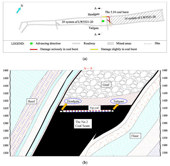
Figure 1.
Layout of the 5521-20 working face: (a) Layout of the working face; and (b) A—A Profile.
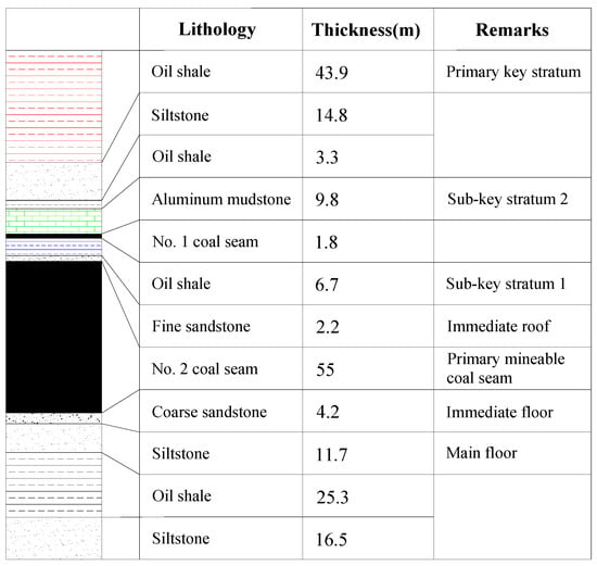
Figure 2.
Generalized stratigraphic column of the geological borehole.
2.2. The “3.24” Rock Burst in 5521-20 Working Face
At 1:50 a.m. on 24 March 2016, a rock burst occurred when the 5521-20 working face was being mined; its location is shown in Figure 1b. In total, 19 pairs of hydraulic supports were broken in the 5521-20 working face, in which the props of the hydraulic supports were bent and broken due to floor heave of the bottom coal, as shown in Figure 3a. The maximum lifting height was 1.5 m for the coal on roof side and the damage to the hydraulic supports on the roof side was more serious than those on floor side. Four large cracks with a width of 0.15–0.2 m appeared in the bottom coal due to strong shear failures, as shown in Figure 3b.
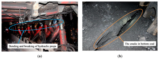
Figure 3.
Photos of the “3.24” rock burst in the 5521-20 working face: (a) Failure of hydraulic supports; and (b) Cracking of the bottom coal in headgate.
3. Numerical Simulation Using Discrete Element Methods
3.1. UDEC Trigon Method
The Universal Distinct Element Code (UDEC) is a two-dimensional numerical program based on the discrete element method. A material in the UDEC model is represented by blocks bonded along contacts [20]. The UDEC Trigon method was proposed by Gao and Stead [21]. In this logic, failures only occur along the contacts, depending on the strength and the stress of the contact surfaces. The relationship between displacement and stress is as follows:
In the normal direction of contact:
There is a limiting tensile strength, , for any contact.
If , then
where is the normal stress of the contact, and are the effective normal stress increment and normal displacement increment, respectively, and is the normal stiffness of the contact.
Otherwise, if , then .
In the shear direction of contact:
There is a limiting shear strength, , for any contact:
If , then
otherwise, if , then
where is the shear stress of the contact, and are the cohesion and the friction of the contact, respectively, and are the elastic component of the incremental shear displacement and total incremental shear displacement, respectively, and is the shear stiffness of the contact.
3.2. Model Configuration
A UDEC Trigon model was built to simulate the evolution of the overlying strata and the distribution of stress in the coal and rock mass during horizontal section mining of an SIETCS. The 2D model was 2307 m wide × 820 m high, as shown in Figure 4a. It was impossible to adopt UDEC Trigon logic for every part of the model. In order to reduce the computational time and obtain a higher efficiency, we used the UDEC Trigon logic only in the area of interest, as shown in Figure 4b. The average edge length of the triangular blocks in the area of interest was 0.2 m [22], while that in the surrounding coal area was 0.4 m, 0.8 m, and 1.5 m, respectively. The average length of rectangular blocks was 1 m, 2 m, 4 m, 8 m, 16 m, 32 m, and 64 m, respectively. A model with 20 sections, each section being 15 m high, was established. The lateral boundaries and the bottom boundary were fixed in displacement.
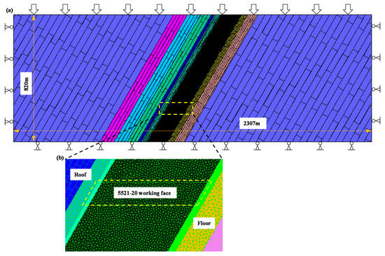
Figure 4.
Model overview: (a) Configuration of the entire model; and (b) The area of interest.
3.3. Calibration of the Simulation Parameters
There are several micro-properties of contacts in the UDEC Trigon model, including the normal stiffness (), shear stiffness (), cohesion, friction, and tensile strength. These properties control the mechanical behavior of the materials. It is important to obtain reasonable and reliable micro-properties. The micro-properties must be calibrated before using the model.
There are four steps in the calibration process [22,23]: First, the uniaxial compressive strength (UCS) and deformation modulus of the coal and rock are acquired by performing a laboratory unconfined compression test.
Then, the deformation modulus and UCS of the rock mass were calculated, according to the experimental results of intact rock following the RQD– relation and the relation, respectively, where and are the deformation moduli of the rock mass and the intact rock, respectively, and and are the UCS of the rock mass and the intact rock, respectively. The tensile strength of the rock mass was estimated to be one-tenth of the UCS of the rock mass.
The bulk and shear moduli of blocks were calculated by Equation (7), while the of the materials was calculated using Equation (8). Poisson’s ratio should be assigned to the laboratory value the first time and then calibrated by varying . The value of was 0.2.
The final stage of calibration was a series of tests that were run using the numerical model. In this stage, the micro-properties of contacts, such as cohesion, friction, and tensile strength, should be adjusted until the strength and deformation of the numerical model are in agreement with the rock mass properties.
3.3.1. Rock Mass Properties
The UCS and deformation modulus of the intact coal and rock were obtained through laboratory compression tests, the results are listed in Table 1. The RQD– relation, Equation (5), proposed by Zhang and Einstein [24] based on field monitoring, was applied to estimate the deformation modulus of the rock mass. The RQD value of the rock mass was evaluated using a borehole camera in the 5521-20 working face. The results are listed in Table 1.

Table 1.
Properties of intact rock and rock mass in the Yaojie No.3 Coal Mine.
The UCS of the rock mass was estimated through the relation, Equation (6), proposed by Singh and Seshagiri Rao [25]:
where the value of is 0.56, 0.56, 0.66, and 0.72 for different rock failure types. As the failure modes may be very complicated, the average value (i.e., ) was used in this paper.
The calculated results of the UCS and deformation modulus are listed in Table 1.
3.3.2. Contact Micro-Parameters
The values of contact micro-parameters were calculated and the Trigon logic numerical models were established for calibration of the micro-parameters. The values of and were calculated by Equations (7) and (8), respectively.
Here, and are the bulk and shear moduli of the rock mass, respectively, and is Poisson’s ratio for rock.
Here, is the smallest width of the zone and is a scaling factor (usually set to 10).
The calibration models were 2 m wide × 4 m high and were used to simulate the uniaxial compression test, as shown in Figure 5a. There were six contact types to be calibrated, considering all kinds of lithology in the model. The micro-properties are illustrated in Table 2. The results can be seen in Figure 5b and Table 3. We used the residual strengths model in this paper.
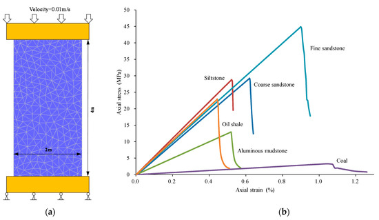
Figure 5.
Calibration of coal and rock mass properties: (a) Calibration model; and (b) Predicted axial stress–axial strain curves of uniaxial compressive strength (UCS).
Table 2.
Calibrated micro-properties in the Universal Distinct Element Code (UDEC) Trigon model.
Table 3.
Calibrated results of rock mass properties in the Trigon model.
3.4. In Situ Stresses and Modelling Sequence
In situ stress measurements were performed near the study site. An in situ stress state with vertical stress and horizontal stress was imposed in the model, according to the results.
In the model, a horizontal section with a height of 15 m per section was excavated, as illustrated in Figure 6. Each section represents a working face. The 5521-20 working face is the 20th section.
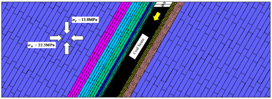
Figure 6.
In situ stress and excavation procedures adopted in the UDEC model.
4. Modelling Results and Field Observations
The evolution laws of structures and stresses of the rock and coal and their effect on rock bursts in the horizontal section mining of the SIETCS were studied. This was achieved by evaluating the simulated roof breakage, stresses in rock and coal, fracture patterns of bottom coal, and displacements of the rock and coal, combined with field tests. The evolution process of the roof structures during horizontal section mining in the SIETCS is shown in Figure 7. The simulated stress and displacement were monitored (see Figure 8 and Figure 9). The fracture patterns of the bottom coal in the working face are shown in Figure 10. The distribution of stress in the rock and coal along the inclination of the working face was summarized by combining the stress state and failure modes of the bottom coal, as shown in Figure 11. The modelling results were validated by field monitoring. The breakage of the roof and instability of the structures of the roof were monitored using an SOS micro-seismic monitoring system, as shown in Figure 12 and Figure 13. Finally, the sources of dynamic loads and static stresses and mechanisms of rock bursts in the horizontal section mining of the SIETCS were proposed, as shown in Figure 14.
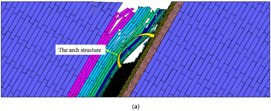
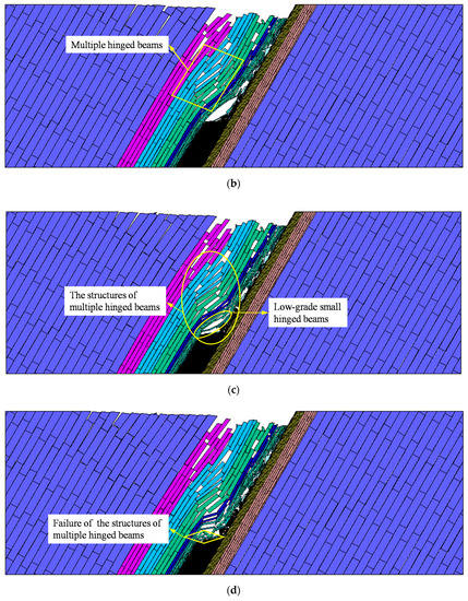
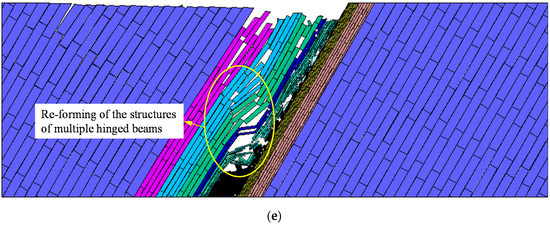
Figure 7.
Simulated roof breakage in horizontal section mining of steeply inclined extra-thick coal seams (SIETCS): (a) Mining in the 12th section; (b) Mining in the 17th section; (c) Mining in the 19th section; (d) Mining in the 21st section; and (e) Mining in the 23rd section.
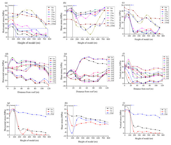

Figure 8.
Simulated stress in the roof, bottom coal, and floor: (a) Horizontal stress in the roof; (b) shear stress in the roof; (c) vertical stress in the roof; (d) horizontal stress in bottom coal; (e) shear stress in bottom coal; (f) vertical stress in bottom coal; (g) horizontal stress in the floor; (h) shear stress in the floor; (i) vertical stress in the floor; and (j) measuring lines in the model.
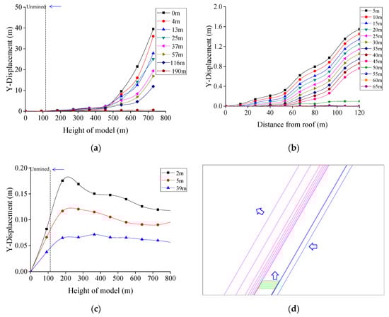
Figure 9.
Simulated displacements in the roof, bottom coal, and floor: (a) Displacement in the roof; (b) displacement in bottom coal; (c) displacement in the floor; and (d) measuring lines in the model.
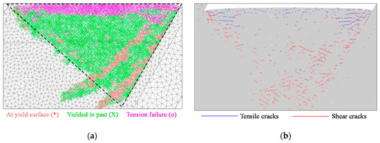
Figure 10.
Simulated fracture patterns in bottom coal of working face: (a) Plastic state of zones in bottom coal; and (b) Distribution of cracks (shear cracks in red and tensile cracks in blue) in bottom coal.
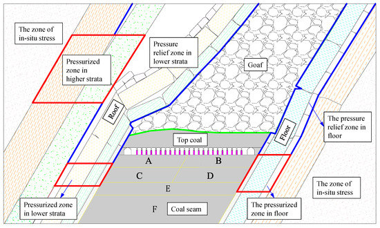
Figure 11.
Distribution of stress in coal and rock along the inclination of the working face.
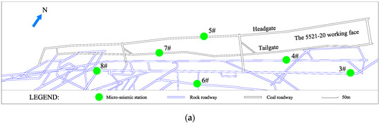
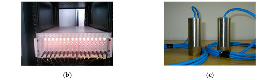
Figure 12.
SOS micro-seismic monitoring system: (a) Dispersion of micro-seismic stations; (b) DLM-SO signal acquisition station; and (c) Vibration sensors.
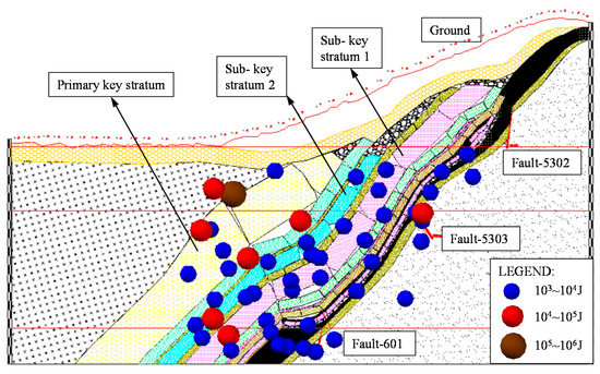
Figure 13.
Localization map of recorded seismic events from 10 February 2017 to 10 March 2017.
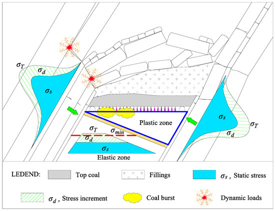
Figure 14.
The mechanisms of rock burst in SIETCS.
4.1. Evolution of the Structures in Roof
The form of the structures in roof changed from an arch structure to a multiple hinged beam structure during SIETCS mining. Figure 7 shows the simulated breakage of the roof and roof structures.
In comparison with the mining of flat seams and gently inclined seams, the roof strata of SIETCS show a larger angle in the horizontal direction, while component of gravity in overlying strata along the normal direction of the bedding is smaller. As a result, during horizontal section mining of SIETCS in shallow parts, sub-key strata gradually bend and sink with the multi-section mining of coal seams, thus forming an arch structure, rather than hinged beams formed by obvious fracturing and rotation, as shown in Figure 7a.
When starting to mine in deep parts, due to the influences of factors such as enlargement of the goaf, increase of in situ stress, and decrease of rock intensity induced by fatigue damage, key strata are gradually fractured and overlapped and the arch structure changed to hinged beams. This can be intuitively seen by comparing Figure 7a,b. It is clear that the hinged beams were formed in this stage, having a large span and remaining relatively intact. As the space of the goaf further rises, the beams gradually rotated and the angle in the horizontal direction decreases; meanwhile, the static loads on beams are rising and horizontal extrusion forces from the roof and floor are continuously enlarging due to the increase of mining depth. Thus, the hinged beams formed by initial fracturing are fractured, rotated again, and interlocked with each other. Low-grade small-hinged beam structures are formed near the working face, as shown in Figure 7b. The hinged beams are formed in the main and sub-key strata in the roof. They are mutually independent and influenced. Multiple hinged beams are superposed and combined into structures having a certain bearing capacity, as shown in Figure 7c. By comparing the forms of overlying strata during mining, it was found that the multiple hinged beam structures experienced repeated instability when 3–4 sections were mined (15 m in height per section), as per the law of periodic instability of structures of multiple hinged beams during the horizontal section mining of SIETCSs. The instability of the large structures formed by overlying key strata exerts an important influence on rock bursts in the working face. In addition, as the goaf in the SIETCS constantly extends downward, the overlying strata are repeatedly affected by mining disturbances. The continuous accumulation of damage may weaken the strength of the surrounding rocks. This easily exacerbates breakage of the overlying strata and shortens the steady-state period of the structures of multiple hinged beams; thus, strong dynamic loads are formed.
4.2. Distribution of Stress
In order to study the distribution characteristics of stress and displacement in the rock and coal during the horizontal section mining of the SIETCS, 23 measuring lines in total were arranged along the bedding of the coal and rock strata, as shown in Figure 8. Of these, 8 measuring lines on the roof side were 0 m, 4 m, 13 m, 25 m, 37 m, 57 m, 116 m, and 190 m away from the immediate roof in the normal direction along the strata; 12 measuring lines were arranged at intervals of 5 m in the bottom coal; and three lines on the floor side were 2 m, 5 m, and 39 m away from the immediate floor in the normal direction along the strata. The distribution laws of stress and displacement in the coal and rock mass were analyzed when the residual height of the model was 115 m.
Changes of stress in the roof with height of the model are presented in Figure 8a–c. The distributions of horizontal, vertical, and shear stresses along the directions of the rock bedding were consistent, first rising and then decreasing. For the convenience of description, the lower strata in this work refers to the roof below the primary key stratum—that is, in the range of 0–39 m in the normal direction from the roof—while the primary key stratum and the roof above are called higher strata. Under clamping of the roof and floor and the hanging roof effects in a small range near the working face, the lower roof forms a pressurized zone in the range of 10–45 m below the mining level, where the stress concentration factor is 1.0–1.5. In this zone, the roof is mainly subjected to squeeze stress and compression–shear failure. In the goaf, the lower strata are influenced by pressure relief effects, as the coal seam had been mined and roof had broken, such that the stress level is relatively lower on the whole in this area. The lower strata are also in a pressure relief zone. However, the higher strata are in a state of separating and fracturing gradually, thus forming a higher pressurized zone which is 39–116 m in the normal direction from the roof and 115–365 m above the mining level with a stress concentration factor ranging from 1.5 to 2.0. The stresses in further roof strata are slightly affected by mining, such that this area can be considered as a zone of in situ stress.
As shown in Figure 8g–i, the distribution of stress in the floor is simpler, compared with the roof stress. It can be divided into two zones: one is a pressurized zone in the floor ranging from 0–50 m below the mining level with stress concentration factor of 1.1–1.3, while the other is a pressure relief zone in the floor in the goaf. The rest of the floor strata are in the zone of in situ stress.
As an important medium in rock bursts, the stress distribution characteristics in the bottom coal of the working face should be paid full attention. Changes of stress in the bottom coal with distance from roof are shown in Figure 8d–f. In the horizontal co-ordinate, 0 m and 120 m represent the roof side and floor side, respectively. Under the asymmetric effects of the roof and floor, the stress state of the bottom coal shows different characteristics along the inclination: High stress on the roof side and low stress on the floor side. Due to squeezing of the roof, a high stress state is formed in the range of 0–20 m from the roof along the inclination, compared with the floor side. The bottom coal on the floor side is largely deformed and the level of stress is relatively low. Under the pressure relief effects of mining, the bottom coal 0–15 m below the level of the working face lies in the pressure relief zone, except for the coal on the roof side. Due to clamping force of the roof and floor, stress-increased zones are formed in the bottom coal on the roof and floor sides within 15–40 m below the mining level. Stress on the roof side obviously rises and the stress concentration factor is 1.2–2.0, while the stress in the pressurized zone of the floor side increases little, due to large deformations. The stress of the bottom coal fluctuates with small amplitude in the range of 40–55 m below the mining level, such that it can be classified as a stress disturbance zone. When the depth is larger than 55 m, the changes of stress in the bottom coal are small, such that it could be considered as at the initial stress state.
Displacement measuring lines were arranged in the model, as shown in Figure 9d. The displacements of the roof and floor are shown in Figure 9a,c, respectively. The displacement of the roof is large, showing a power exponential relationship with the height of the model. The displacement of the floor is smaller than that of the roof. The displacement of the bottom coal in the working face with distance from the roof is shown in Figure 9b. It shows different characteristics along the inclination: low displacement on the roof side and high displacement on the floor side.
The simulated fracture patterns of the bottom coal in the working face are shown in Figure 10. There is a triangle plastic failure area of the bottom coal in the working face after horizontal section mining of the SIETCS, as shown in Figure 10a. This area has the characteristics of centralized distribution on the floor side under the asymmetric effects of the roof and floor, such that the bottom coal on the floor side is broken seriously and shows large deformation. However, the plastic failure depth of the bottom coal on the roof side is relatively small. Under the clamping action of the roof and floor, the bottom coal on the roof side is in a high static stress state, becoming the main area with a high risk of rock burst in horizontal section mining of the SIETCS. Tension failures occur in the shallow part and shear failures in the deep part of the bottom coal in the working face, as shown in Figure 10b.
Based on the above analysis, the stress distribution in the rock and coal along the inclination of the working face in SIETCS was proposed, as shown in Figure 11. There are high stress zones in the roof, floor and bottom coal of the working face, caused by clamping of the roof and floor. The distribution of stress in the bottom coal can be described as: The area A is a stress-increased zone on the roof side. The area B is a pressure relief zone on the floor side. The area C is a pressurized zone on the roof side. The area D is a pressurized zone on the floor side. The area E is a stress disturbance zone. The area F is a zone of in-situ stress. They show significant differences under the asymmetric effects.
4.3. Micro-Seismic Monitoring in SIETCS
In order to monitor roof breakages during mining, a SOS micro-seismic monitoring system was installed in the 5521-20 working face of Yaojie No.3 Coal Mine, as shown in Figure 12. The DLM-SO signal acquisition station was used for signal acquisition from vibration sensors. The vibration sensors were used to automatically collect vibration information. This system can accurately calculate mine seismicity with energy larger than 100 J and frequency varying from 0.1 Hz to 600 Hz. Micro-seismic monitoring has been widely used in coal mines [26]. The SOS micro-seismic system has been applied in Poland and in more than 70 coal mines in China. It provides an effective method to study roof breakages and the failure of multiple hinged beam structures [27].
The monitoring results from 10 February 2017 to 10 March 2017 were studied. There were 856 seismic events in total and events with energy level no less than 104 J were selected. The positions of these events are displayed in Figure 13. Each ball of different color and volume represents a micro-seismic event, corresponding to an actual mine seismicity occurring during the process of mining. The increase of volume of the ball indicates a higher energy of mine seismicity and risk of rock burst. Mine seismicity was mainly distributed in roof strata, due to the fracturing of overlying strata. Events with large energy were concentrated on the roof side, indicating that roof fracturing and the instability of multiple hinged beam structures could easily induce mine seismicity with high energy, which are main sources of the dynamic loads of rock bursts in SIETCSs. There were also a certain number of micro-seismic events at low energy level in the bottom coal of the working face, demonstrating that the bottom coal of the working face was fracturing under the clamping effects of the roof and floor, which led to high static stress.
4.4. Mechanisms of Rock Burst in Horizontal Section Mining of SIETCS
Based on the numerical modelling and field monitoring results, the mechanisms of rock bursts induced by the horizontal section mining of SIETCSs could be proposed, as shown in Figure 14. The bottom coal in the working face was in a state of high static stress through the clamping of the roof and floor, which could be divided into two sub-areas, according the failure modes and deformation of coal under the asymmetric effects of the roof and floor. There was a triangular plastic zone on the floor side and an elastic zone on the roof side. The static stress in the elastic zone was higher than that in the plastic zone, due to squeezing of the roof. Strong dynamic loads were formed by breakage of roof and the failure of multiple hinged beam structures due to mining. The stress increment appeared in the rock and coal under the influence of dynamic load propagation; thus, a new stress was formed due to the superimposition of the static stress and the stress increment in rock and coal:
Rock bursts will occur when , where is the critical stress of the coal and rock.
5. Technical Scheme of Rock Bursts Prevention and Its Effects
5.1. Principles of Rock Bursts Prevention
Based on the mechanisms of rock bursts induced by the superposition of dynamic loads and static stress, the following principles of prevention are proposed: (1) under the existing technical conditions, deep-hole pre-split blasting should be carried out with a hard and thick roof in a controllable range, in order to prevent dynamic loads caused by the sudden breakage of the roof or structural instability; and (2) destress blasting and destress holes should be conducted in the roadway, in order to reduce the static stress in the coal mass.
5.2. Technical Scheme in Field
A pressure-relief and risk-reduction scheme for the 5521-20 working face was designed, based on the principles proposed above. Figure 15 shows the profile of deep-hole pre-split blasting with a hard roof, as well as destress blasting and destress holes in the headgate. The 1#, 2#, and 3# holes are deep-hole pre-split blasting holes to prevent strong dynamic loads. The 4# hole is a destress blasting hole in the bottom coal and the 5# hole is a destress hole in the working face rib of the headgate. The design parameters of the 1#–5# holes are shown in Table 4. As a result, the static stress in the bottom coal and stress increment induced by dynamic loads can both be decreased effectively.
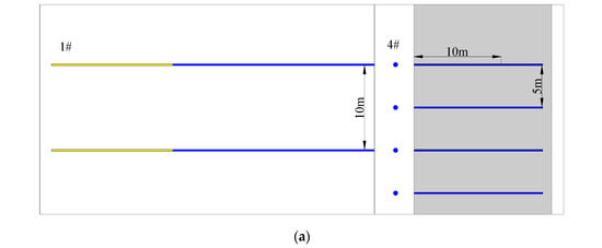
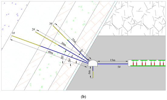
Figure 15.
Layout of technical scheme for rock burst prevention in the 5521-20 working face: (a) Plan of the technical scheme; and (b) profile of the technical scheme.
Table 4.
Design parameters for the 1#–5# holes.
5.3. Analysis of Prevention Effects
Gutenberg and Richter [28] found that a power relationship exists between earthquake frequency and magnitude by studying the characteristics of seismic activities. The G–R relational expression was proposed as follows:
where and represent the magnitude and frequency of earthquakes, respectively, and and are constants. The value of reflects the level of seismic activity: The larger its value, the more earthquakes happen. The value of indicates the intensity of earthquakes: the larger its value, the larger the proportion of earthquakes at low energy level in the total number of earthquakes, such that that intensities of earthquakes are relatively low.
Cai et al. [29] have achieved good effects by applying the value for the prediction of rock bursts in coal mines. The higher the value of , the lower the risk of rock bursts. Based on the SOS micro-seismic monitoring data, prevention effects were evaluated through value analysis, as shown in Figure 16. After applying the technical scheme to the 5521-20 working face, the value changed from about 0.45 in stage I to about 0.55 in stage II and rose to about 0.65 in stage III, indicating that the proportion of mine seismicity at low energy levels gradually increased. The proportion of mine seismicity with large energy obviously reduced, suggesting that the adopted prevention scheme enables elastic energy around the working face to be released in the form of more micro-seismic events with small energy and improves the stress state and energy release environment around the working face. The risk of rock bursts decreased significantly, indicating a good prevention effect.
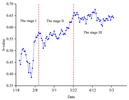
Figure 16.
Change of value.
6. Conclusions
In this paper, the mechanisms of rock bursts were studied during the horizontal section mining of a steeply inclined extra-thick coal seam (SIETCS) by numerical simulation and field tests. Then, a technical prevention scheme was proposed, and its prevention effects were analyzed based on micro-seismic monitoring data. We draw the following conclusions:
A UDEC Trigon model was developed to simulate the evolution of the overlying strata structures and the stress distribution in rock and coal under horizontal section mining of an SIETCS. The input parameters were calibrated. The sources of dynamic loads and static stress of rock bursts in the horizontal section mining of the SIETCS were proposed. Strong dynamic loads are formed due to breakage of the roof and the failure of multiple hinged beam structures, which is the main factor of rock bursts in SIETCSs. Stress concentration degrees in the rock and coal around the roof side are higher than those on the floor side, due to the asymmetric clamping effects due to the roof and floor. It should be noted that a triangular plastic zone was formed in the coal on the floor side.
The mechanisms of rock bursts during the horizontal section mining of SIETCSs were proposed. The coal in the elastic zone around the roof side is in a high static stress state under the asymmetric clamping and squeezing of the roof and floor. Strong dynamic loads are thus formed by breakage of the roof and the failure of multiple hinged beam structures. Rock bursts occur when the superimposition of the static stress and stress increment induced by these dynamic loads is greater than the critical stress, , of the coal and rock.
A pressure-relief and risk-reduction technical scheme was constructed for the 5521-20 working face of Yaojie No.3 Coal Mine. Analysis of the value was applied to evaluate its prevention effects. Field applications show that the value increased from 0.45 to 0.65, indicating that the risk of rock burst decreased significantly. The proposed technical scheme provides a basis for preventing and controlling rock bursts under similar conditions.
Author Contributions
Conceptualization, L.D. and J.C.; Methodology, J.C.; Software, J.C.; Validation, J.C. and S.W.; Formal Analysis, J.C., J.H., S.W. and K.Z.; Investigation, G.Z., J.H. and J.C.; Resources, L.D. and J.H.; Data Curation, J.C., L.D., and G.Z.; Writing-Original Draft Preparation, J.C.; Writing-Review & Editing, J.C.; Visualization, J.C., S.W., G.Z. and K.Z.; Supervision, L.D., G.Z. and J.H.; Project Administration, L.D. and J.H.; Funding Acquisition, L.D. and G.Z. All authors have read and agreed to the published version of the manuscript.
Funding
This research received no external funding.
Acknowledgments
This work was supported and financed by National Natural Science Foundation of China (Grant No. 51874292 and 51934007) and the China Postdoctoral Science Foundation (Grant No. 2018M643692). The authors thank Yaojie No.3 Coal Mine for their support during the field tests.
Conflicts of Interest
The authors declare no conflict of interest regarding the publication of this paper.
References
- Srinivasan, C.; Arora, S.K.; Yaji, R.K. Use of mining and seismological parameters as premonitors of rockbursts. Int. J. Rock Mech. Min. Sci. 1997, 34, 1001–1008. [Google Scholar] [CrossRef]
- Iannacchione, A.T.; Zelanko, J.C. Occurrence and Remediation of Coal Mine Bursts: A Historical Review; Special Publication; US Department of the Interior; U.S. Bureau of Mines: Washington, DC, USA, 1995; pp. 27–68.
- Mark, C. Coal bursts in the deep longwall mines of the united states. Int. J. Coal Sci. Technol. 2016, 3, 1–9. [Google Scholar] [CrossRef]
- Ortlepp, W.D. Rasim comes of age—A review of the contribution to the understanding and control of mine rockbursts. In Proceedings of the Sixth International Symposium on Rockburst and Seismicity in Mines, Perth, Australia, 9–11 March 2005; pp. 9–11. [Google Scholar]
- Hebblewhite, B.; Galvin, J. A review of the geomechanics aspects of a double fatality coal burst at Austar Colliery in NSW, Australia in April 2014. Int. J. Coal Sci. Technol. 2017, 27, 3–7. [Google Scholar] [CrossRef]
- Mohammad, J.; Rabindra, K. Design of rhombus coal pillars and support for Roadway Stability and mechanizing loading of face coal using SDLs in a steeply inclined thin coal seam—A technical feasibility study. Arab. J. Geosci. 2018, 11, 415. [Google Scholar]
- Li, X.; Wang, Z.; Zhang, J. Stability of roof structure and its control in steeply inclined coal seams. Int. J. Min. Sci. Technol. 2017, 27, 359–364. [Google Scholar] [CrossRef]
- Wang, H.; Wu, Y.; Liu, M.; Jiao, J.; Luo, S. Roof-breaking mechanism and stress-evolution characteristics in partial backfill mining of steeply inclined seams. Geomat. Nat. Hazards Risk 2020, 11, 2006–2035. [Google Scholar] [CrossRef]
- Cui, F.; Lei, Z.; Chen, J.; Chang, B.; Yang, Y.; Li, C.; Jia, C. Research on Reducing Mining-Induced Disasters by Filling in Steeply Inclined Thick Coal Seams. Sustainability 2010, 11, 5802. [Google Scholar]
- Yang, S.; Li, L.; Deng, X. Disaster-causing mechanism of roof “toppling–slumping” failure in a horizontal sublevel top-coal caving face Stability of roof structure and its control in steeply inclined coal seams. Nat. Hazards 2020, 100, 757–780. [Google Scholar] [CrossRef]
- Wu, G.; Chen, W.; Jia, S.; Tan, X.; Zheng, P.; Tian, H.; Rong, C. Deformation characteristics of a roadway in steeply inclined formations and its improved support. Int. J. Rock Mech. Min. Sci. 2020, 130, 104324. [Google Scholar] [CrossRef]
- Yang, Y.; Lai, X.; Shan, P.; Cui, F. Comprehensive analysis of dynamic instability characteristics of steeply inclined coal-rock mass. Arab. J. Geosci. 2020, 13, 241. [Google Scholar] [CrossRef]
- Xie, P.; Luo, Y.; Wu, Y.; Cao, X.; Luo, S.; Zeng, Y. Roof Deformation Associated with Mining of Two Panels in Steeply Dipping Coal Seam Using Subsurface Subsidence Prediction Model and Physical Simulation Experiment. Metall. Explor. 2020, 37, 581–591. [Google Scholar] [CrossRef]
- Wang, S.; Dou, L.; Mu, Z.; Cao, J.; Li, X. Study on Roof Breakage-Induced Roadway Coal Burst in an Extrathick Steeply Inclined Coal Seam. Shock Vib. 2019, 2019, 2969483. [Google Scholar] [CrossRef]
- He, S.; Song, D.; He, X.; Chen, J.; Ren, T.; Li, Z.; Qiu, L. Coupled mechanism of compression and prying-induced rock burst in steeply inclined coal seams and principles for its prevention. Tunn. Undergr. Space Technol. 2020, 98, 103327. [Google Scholar] [CrossRef]
- He, S.; Song, D.; Li, Z.; He, X.; Chen, J.; Li, D.; Tian, X. Precursor of Spatio-temporal Evolution Law of MS and AE Activities for Rock Burst Warning in Steeply Inclined and Extremely Thick Coal Seams Under Caving Mining Conditions. Rock Mech. Rock Eng. 2019, 52, 2415–2435. [Google Scholar] [CrossRef]
- Wang, Z.; Dou, L.; Wang, G. Coal Burst Induced by Horizontal Section Mining of a Steeply Inclined, Extra-Thick Coal Seam and Its Prevention: A Case Study from Yaojie No. 3 Coal Mine, China. Shock Vib. 2019, 2019, 8469019. [Google Scholar] [CrossRef]
- He, J.; Dou, L.; Gong, S.; Li, J.; Ma, Z. Rock burst assessment and prediction by dynamic and static stress analysis based on micro-seismic monitoring. Int. J. Rock Mech. Min. Sci. 2017, 93, 46–53. [Google Scholar] [CrossRef]
- Qian, M.; Shi, P.; Xu, J. Mining Pressure and Strata Control; China University of Mining and Technology Press: Xuzhou, China, 2010. (In Chinese) [Google Scholar]
- ITASCA. UDEC (Universal Distinct Element Code); Version 6.0; Itasca Consulting Group Inc.: Minneapolis, MN, USA, 2014. [Google Scholar]
- Gao, F.; Stead, D. The application of a modified Voronoi logic to brittle fracture modelling at the laboratory and field scale. Int. J. Rock Mech. Min. Sci. 2014, 68, 1–14. [Google Scholar] [CrossRef]
- Gao, F.; Stead, D.; Kang, H. Numerical Simulation of Squeezing Failure in a Coal Mine Roadway due to Mining-Induced Stresses. Rock Mech. Rock Eng. 2015, 48, 1635–1645. [Google Scholar] [CrossRef]
- Wu, W.; Bai, J.; Wang, X.; Yan, S.; Wu, S. Numerical Study of Failure Mechanisms and Control Techniques for a Gob-Side Yield Pillar in the Sijiazhuang Coal Mine, China. Rock Mech. Rock Eng. 2019, 52, 1231–1245. [Google Scholar] [CrossRef]
- Zhang, L.; Einstein, H.H. Using RQD to estimate the deformation modulus of rock masses. Int. J. Rock Mech. Min. Sci. 2004, 41, 337–341. [Google Scholar] [CrossRef]
- Singh, M.; Rao, K.S. Empirical methods to estimate the strength of jointed rock masses. Eng. Geol. 2005, 41, 127–137. [Google Scholar] [CrossRef]
- Ge, M. Efficient mine microseismic monitoring. Int. J. Coal Geol. 2005, 64, 44–56. [Google Scholar] [CrossRef]
- Zhao, Y.; Yang, T.; Zhang, P.; Zhou, J.; Yu, Q.; Deng, W. The analysis of rock damage process based on the microseismic monitoring and numerical simulations. Tunn. Undergr. Space Technol. 2017, 69, 1–17. [Google Scholar] [CrossRef]
- Gutenberg, B.; Richter, C.F. Frequency of earthquakes in California. Bull. Seismol. Soc. Am. 1944, 34, 185–188. [Google Scholar]
- Cai, W.; Dou, L.; Zhang, M.; Cao, W.; Shi, J.; Feng, L. A fuzzy comprehensive evaluation methodology for rock burst forecasting using microseismic monitoring. Tunn. Undergr. Space Technol. 2018, 80, 232–245. [Google Scholar] [CrossRef]


Publisher’s Note: MDPI stays neutral with regard to jurisdictional claims in published maps and institutional affiliations. |
© 2020 by the authors. Licensee MDPI, Basel, Switzerland. This article is an open access article distributed under the terms and conditions of the Creative Commons Attribution (CC BY) license (http://creativecommons.org/licenses/by/4.0/).