Abstract
Motorized spindle system is one of the crucial components affecting the machine tools energy performance. Many previous studies have examined its energy optimization problems, however, most such studies focused mainly on parameters optimization to improve material removal energy efficiency or reduce total energy consumption. A missing research area is energy optimization problem considering thermal stability and productivity constraints simultaneously. Against this background, an energy optimization approach of motorized spindle system is presented with consideration of thermal stability and productivity adequately, with the goal of maximization of energy efficiency and material removal rate, and minimization of spindle average temperature which is closely associated with thermal stability. Firstly, the energy characteristics of motorized spindle and its cooling system are mathematically modelled. Then, a multi-objective optimization model is established to take the maximum energy efficiency, minimum spindle average temperature, and maximum material removal rate as objectives. The optimal solution is obtained by solving the proposed optimization model with the Non-dominated Sorted Genetic Algorithm-II (NSGA-II). Finally, a case study is introduced to validate the proposed method and the results indicate that the proposed method is more effective to find optimal decision variables for balancing the considered objectives compared with the existing optimization method.
1. Introduction
Driven by increasingly pressures from economic costs as well as environmental emissions, energy-efficient has become an important issue faced by manufacturing for sustainability [1,2,3]. Without a doubt, this is particularly important for machine tools due to their extensively used in manufacturing, low energy efficiency, and high potential impact on the environment [4]. Therefore, improving energy efficiency of machine tools is critical and a major battlefield for achieving energy-efficient manufacturing [5].
In recent years, enormous efforts have been spent on energy efficiency optimization of machine tools from both design and operation perspectives. For energy-efficient design of machine tools, lightweight design and structure optimization are the key research points [6,7,8]. Regarding optimal operation of machine tools, a great deal of research has been carried out ranging from process level [9,10,11], component level [12,13,14,15,16], and machine tool level [17,18,19]. It is observed from the current research that process parameters optimization is an effective method for improving machine tools or their components energy efficiency unchanging their mechanical structure and without additional accessories. By optimizing process parameters under a series of constraints, the energy efficiency of machine tools can be improved significantly [20]. Another interesting observation from literature review is that the spindle system is responsible for a significant portion of energy consumption of machine tools [7,12,21]. Moreover, the energy consumption characteristics of the whole machine tools depend on the working condition of spindle system to a certain extent [22]. Hence, the energy optimization of spindle system is one of the most profitable strategies for improving energy efficiency of machine tools.
Liu et al. [23] proposed a prediction approach for energy consumption for mechanical spindle system of machine tools in turning process based on analytical model and data fitting. This study lays a foundation for the energy optimization of machine tool spindle system. Based on this work, Lv et al. [24] investigated the energy consumption of spindle system during the acceleration stage and approaches from machine tool and machining system levels for energy consumption reduction in this stage were developed.
With the increasing demand of high-speed machining, motorized spindle system is widely equipped in the modern machine tools and studies on energy consumption and energy optimization of motorized spindle system of machine tools were also carried out systematically by scholars [25]. Although the motorized spindle eliminates the power losses induced by mechanical transmission chains, the integration of motor and spindle generates intensive heat in the motorized spindle, which results in large spindle thermal deformation and poor machining quality. The spindle cooling system is therefor designed to dissipate the generated heat and mitigate the spindle thermal deformation, but it increases the energy consumption of the motorized spindle system. It is worth noting that the energy consumption of spindle cooling system is essential to control the thermal deformation and maintain the machining quality. Therefore, the energy consumption of spindle cooling system for thermal deformation control should be considered as important as the material removal energy consumption. However, it has not been taken into consideration in most published researches on energy efficiency of motorized spindle system. On the other hand, the objectives of energy efficiency, thermal effects and productivity of motorized spindle system are naturally in conflict with each other [26], improving energy efficiency should not deteriorate thermal effects and productivity [27,28]. Therefore, the mentioned three objectives should be balanced when performing motorized spindle system optimization rather than focusing merely on energy optimization. However, very little research work has been performed on this area.
Motivated by the above remarks, this paper develops a new energy efficiency optimization model for motorized spindle system of machine tools considering minimum temperature rise of motorized spindle and maximum material removal rate simultaneously. Wherein, the temperature rise of motorized spindle is closely associated with its thermal deformation and machining quality and the material removal rate is positively correlated with productivity. The novelty and contributions of this paper are as follows:
- A novel energy efficiency model of motorized spindle system with exergy concept is developed by taking the energy consumption for material removal and thermal deformation control as useful energy consumption.
- A multi-objective optimization model is proposed with the objectives of maximum energy efficiency, minimum spindle average temperature, and maximum material removal rate.
- The feasibility and effectiveness of the proposed optimization model are validated by a case study and the optimal decision variables are discovered by solving the proposed model.
The rest of the paper is arranged as follows. In Section 2, the energy characteristics of the motorized spindle and its cooling system are mathematically modelled. In Section 3, a multi-objective optimization model of motorized spindle system is developed by taking maximum overall exergy efficiency, maximum material removal rate, and minimum spindle average temperature at thermal equilibrium state as objectives. In Section 4, a case study is introduced for validating the proposed optimization model. Finally, the innovative conclusions and future work are listed in Section 5.
2. Energy Modelling of Motorized Spindle System
2.1. Composition of Motorized Spindle System
The motorized spindle system is widely used in modern machine tools for its productivity improvement. A typical motorized spindle system is composed of a built-in spindle motor, an air compression unit, and a water-cooling machine, as shown in Figure 1. The electrical power (Pmotor) supplied to spindle motor will be converted into mechanical power (Pme) for workpiece material removal. Almost all electrical energy losses due to motor efficiency and friction will be converted into thermal energy accumulated in the spindle motor and bearings, which directly result in temperature rise and thermal deformation of the motorized spindle. Spindle cooling system is therefore designed to dissipate the generated heat and mitigate the temperature rise and thermal deformation. The water-cooling machine is used to dissipate the generated heat in built-in motor by circulating the cooling water (flow rate of ṁw and temperature of Tw,in). Compressed air (flow rate of ṁca and temperature of Tca,in) is supplied to generate oil-mist for achieving lubrication of spindle bearings and dissipation of generated heat.
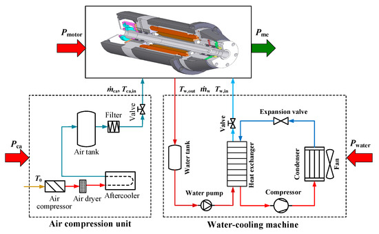
Figure 1.
Energy boundaries of the motorized spindle system.
2.2. Energy Characteristics Modelling
2.2.1. Spindle Motor Power Model
The electrical power consumption of spindle motor consists of mechanical power output for workpiece material removal and electrical power losses due to bearing friction and air viscous friction. Spindle motor power is then expressed by the following Equation (1) [29].
where Pmotor represents the electrical power input of spindle motor, ηmotor is the efficiency of spindle motor, Pme, Pbrg,Fr, Pwind are the mechanical power output for workpiece material removal, the power loss due to bearing friction, and the power loss induced by air viscous friction, respectively.
The mechanical power output for workpiece material removal is a function of spindle speed and cutting load, which can be calculated by the following Equation.
where n is the spindle rotation speed, Fc is the main cutting force, and Dw and DT are the diameter of machined workpiece and cutting tool, respectively.
The power loss induced by bearing friction is made up of the friction torques induced by external cutting load and lubricant viscous friction, where the friction torque caused by external cutting load and by lubricant viscous friction can be calculated from the following Equations (3) and (4) [30].
where z and y are respectively equal to 0.001 and 0.33 for angular contact bearing, Fs is the static equivalent load, Cr is the basic static load rating, Fa is the axial load. ν is the kinematic viscosity, n is the spindle speed, and f0 is equal to 4 for a pair of angular contact grease lubricated bearings [31].
Therefore, the power loss caused by bearing friction is calculated by the following Equation.
According to Reference [29], the power loss due to air viscous friction can be calculated by the following Equation.
where dr and ds represent the diameters of spindle rotor and stator, respectively, lr is the length of spindle rotor, μair is the dynamic viscosity of air, fr is the frequency of spindle rotor.
2.2.2. Spindle Cooling Power Model
The spindle cooling system is composed of water-cooling machine and air compression unit. Therefore, the electrical power demand of spindle cooling system is the total of the power demands of these two units and formulated as the following Equation.
where Pcool is the total power demand of spindle cooling system, Pwater and Pair are the power inputs of water-cooling machine and air compression unit, respectively.
A water pump is used in water-cooling machine to circulate the cooling water with a certain flow rate. The heat of the hot cooling water in the heat exchanger is absorbed by the liquid refrigerant, then the cooled cooling water is delivered to the spindle cooling groove in order to remove the heat generated in spindle motor [32]. The electrical power demand of the water-cooling machine can be expressed a function of the flow rate, pressure, and temperature difference of the cooling water. The total electrical power demand of water-cooling machine can be simply calculated by the following Equation.
where Pwater,p and Pwater,c are the electrical power demand of the water pump and cooling unit, respectively. They can be calculated by the following Equations (9) and (10) [33].
where pw is the pressure of cooling water, ṁw is the mass flow rate of cooling water, ρw is the density of cooling water, ηp is the efficiency of water pump, and ηc is the cooling efficiency.
The electrical power consumption for preparing the compressed air by air compression station can be calculate based on the temperature and flow rate of compressed air. The electrical power demand for compressed air preparation can be calculated by the following Equation (11) [34].
where cca is the heat capacity of compressed air, ṁca is the flow rate of compressed air, Tca,in is the temperature of compressed air, r is the compression ratio, k is the specific heat ratio of compressed air, T0 is the workshop temperature.
3. Multi-Objective Optimization of Motorized Spindle System
3.1. Objective Functions
For motorized spindle system, the larger cutting parameters (spindle speed and feed rate) always correspond to higher production rate (larger material removal rate or smaller material removal time), however, larger material removal rate results in higher energy consumption and larger heat generation. In addition, the pursuit of minimum thermal energy accumulation needs smaller heat generation and larger heat dissipation, which frustrate the productivity and increase the energy consumption of spindle cooling system. The adoption of motorized spindle system is aiming to gain maximum production rate and energy efficiency with minimum thermal deformation of spindle. However, these objectives are conflicting with each other [26]. In order to achieve excellent comprehensive performance of the motorized spindle system, a multi-objective optimization method is brought to deal with this confliction. Three optimization objectives are considered, including (1) overall energy efficiency which is used to measure the energy performance, (2) material removal rate which shows positive correlation with productivity, and (3) spindle average temperature at thermal equilibrium which are closely associated with spindle thermal stability and deformation.
3.1.1. Overall Energy Efficiency
Spindle energy efficiency depends on its thermo-electro-mechanical characteristics. The mechanical energy output for workpiece material removal is of course the numerator of spindle energy efficiency function. Furthermore, it is worth noting that the spindle cooling system is designed to control the thermal stability of motorized spindle and finally ensure the workpiece material removal precision. Hence, a portion of the energy consumption of spindle cooling system, which is equal to the heat dissipated by the cooling mediums should also be regarded as the useful consumption [35].
Since thermal energy is a form of disorganized energy (low-quality energy) and only a portion of it can be converted to work [36], which is inconsistent with electrical and mechanical energy. Based on one of our previous studies [35], exergy, which is based on the first and second laws of thermodynamics, can be used to provide a unified scale to evaluate the electrical, mechanical, and thermal energy. Therefore, by using exergy concept, the overall energy efficiency of motorized spindle system can be calculated by the following Equation.
where tcut and top are respectively the material removal time and spindle operation time, and are respectively the thermal energy dissipation rates of cooling water and compressed air, which are calculated in the following Section 3.1.3. Tms and Tbrg are respectively the temperature of spindle motor and bearings as calculated in the following Section 3.1.3.
3.1.2. Material Removal Rate
Material removal rate is defined as the volume of workpiece material removed per unit time. It can be calculated by dividing the total material removal volume by the cutting time. The cutting time can be calculated according to cutting length and feed rate. The material removal rate and cutting time are modeled in the following Equations.
where MRR is the material removal rate, MRV is the material removal volume, Lcut is the cutting length, and fa is the feed rate at the cutting direction.
3.1.3. Spindle Temperature at Thermal Equilibrium State
In order to obtain the spindle temperature at thermal equilibrium state, the thermal energy accumulation (Qaccum), which is the difference of thermal energy generation and dissipation of the motorized spindle, should be calculated as first. Then, when the thermal equilibrium is reached, dQaccum/dt = 0 can be established to calculate the spindle temperature at this state. Based on one of our previous studies [37], the temperatures of spindle housing and bearing cover can be properly applied to indicate the spindle motor temperature and bearing temperature, respectively. The temperatures of spindle motor and bearing are then expressed as the following Equations (15) and (16) [37].
where Lsphs is the length of spindle housing, Dsphs is the diameter of spindle housing, ksphs is the heat conductivity of spindle housing, Asphs is the convective heat transfer area of spindle housing, is the averaged Nusselt number of natural convective heat transfer of spindle housing, Tstator and Trotor are respectively the stator and rotor temperature, and are respectively the convective heat transfer coefficients of compressed air for stator and rotor, and are respectively the convective heat transfer areas of the stator and rotor, Lbrgco and Dbrgco are respectively the length and diameter of spindle bearing cover, hca,brg is the convective heat transfer coefficient of compressed air for spindle bearing, Abrg is the convective heat transfer area of compressed air for spindle bearing, kbrgco and Abrgco are respectively the heat conductivity and natural convective heat transfer area of spindle bearing cover, and is the averaged Nusselt number of natural convective heat transfer of bearing cover.
The spindle average temperature is then calculated as:
where Tavg is the spindle average temperature, and N is the number of bearing sets.
According to Bergman et al. [38], the convective heat transfer of the cooling water in a helical cooling groove can be considered as the strengthening heat transfer. The heat dissipation rate by cooling water is then calculated as the following Equation.
where dcg and Lcg are respectively the hydraulic diameter and length of cooling groove, and hw is the heat transfer coefficient of cooling water in the cooling groove which can be calculated by the following Equation (19) [39].
where vw is the flow speed of cooling water, μw is the dynamic viscosity of cooling water, Prw is the Prandtl number of the cooling water, λw is the thermal conductivity of cooling water.
According to Bossmanns and Tu [40], the usage of oil in oil-air lubrication for spindle bearings is so small that the heat dissipated by oil can be neglected. It is reasonable to consider only the convective heat transfer between spindle bearings and compressed air. The convective heat transfer rate by compressed air in spindle bearing is calculated as the following Equation.
where the convective heat transfer coefficient and area of compressed air for spindle bearing can be calculated by the following Equations (21) and (22) [39,40].
where dbh is the hydraulic diameter of cooling area by compressed air, dbrg,out and drg,in are respectively the outer ring mean diameter and inner ring mean diameter, dbrg,m is the average diameter of bearing inner ring and outer ring, Prca is the Prandtl number of the compressed air, λca is the thermal conductivity of compressed air, rbrg,out and rbrg,in are respectively the outer raceway curvature radius and inner raceway curvature radius, Nball and dball are respectively the number and diameter of bearing ball.
3.2. Decision Variables
The energy efficiency of the motorized spindle system is determined by the ratio of useful energy output and total electricity consumption. As previously mentioned, the useful energy output consists of mechanical energy for material removal and thermal energy dissipation associated with cooling water and compressed air. The cutting parameters have a decisive impact on the material removal rate and cutting time, moreover, they also affect the material removal energy and total electricity consumption. Furthermore, the adoption of larger cutting parameters will generate more heat in spindle and finally results in higher spindle temperature. Therefore, the cutting parameters are naturally considered as the decision variables, including spindle speed (n), feed rate (f) and depth of cut (ap) for turning; spindle speed (n), feed rate (f), depth of cut (ap) and cutting width (ae) for milling; spindle speed (n) and feed rate (f) for drilling.
Another part should be considered carefully is the spindle cooling system. The operation parameters of spindle cooling system have a significant influence on the total electricity consumption and thermal energy dissipation of the motorized spindle system. The main controllable operation parameters of spindle cooling paraments include the flow rate and temperature of the cooling mediums. According to the technical manual of the motorized spindle, the cooling water temperature should be nearly equal to ambient temperature because extremely high or low temperature may reduce the service life and working performance of the motor. The flow rate of compressed air has an adverse impact on dynamic balance of motorized spindle, therefore, their recommended constant values by manufacturer are considered. Based on the above explanations, the mass flow rate of cooling water (ṁw) and compressed air temperature (Tca,in) are selected as decision variables.
3.3. Constraints
The constraints of the decision variables are divided into two groups. The first group is the reference boundaries provided by manufacturers, as shown in the following Equations.
The second group represents the technical and economic constraints of spindle cooling parameters. The mass flow rate of cooling water is constrained by the required cooling capacity and the maximum power output of water circulation pump. The lower limit of compressed air temperature is determined by the economic available minimum temperature and the upper limit is determined by the minimum temperature of motorized spindle system. The limits of the mass flow rate of cooling water and compressed air temperature are expressed as the following Equations.
3.4. Optimization Model
To explore the most optimal decision parameters for abovementioned objectives, a multi-objective optimization model is introduced: it maximizes the overall energy efficiency and material removal rate and minimizes the spindle temperature at thermal equilibrium state simultaneously under a set of constraints. The multi-objective optimization model of motorized spindle system is expressed as the following Equation.
3.5. Solution Method
To obtain the best combination of decision variables, the popular Non-dominated Sorted Genetic Algorithm-II (NSGA-II) proposed by Deb et al. [41] is introduced in this study to solve the multi-objective optimization problem. In NSGA-II, the non-dominated sorting method and crowding-distance assignment algorithm are adopted to reduce the computational complexity and increase the diversity of solutions, meanwhile, the elitism theory is introduced to enhance the algorithm convergence [41]. Compared with other multi-objective optimization algorithm such as MOGA (Multi-Objective Genetic Algorithm) and SPGA-II (Sub-population Genetic Algorithm II), NSGA-II has great computational efficiency and more capacity to deal with complex multi-objective optimization problems [42]. The solution procedure for the multi-objective optimization is shown in Figure 2. At first, a set of Pareto optimal solutions is obtained by solving the multi-objective optimization model with NSGA-II. Then, a decision-making process should be performed to select the final optimal solution from the obtained Pareto solution set. During this process, Euclidian technique, which is one of the popular nondimensionalization methods, is firstly applied to nondimensionalize the objective function values [43]. After the objective function values being nondimensionalized, the Technique for Order Preference by Similarity to Ideal Solution (TOPSIS) is applied to select the final optimal solution from the Pareto solution set [44,45].
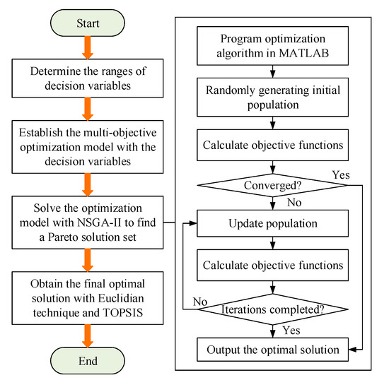
Figure 2.
Solution procedure for the multi-objective optimization problem.
4. Case Study
A type of FANUC motorized spindle used in gear hobbing machine tool was used for performing the proposed multi-objective optimization problem, as show in Figure 3a. The motorized spindle is equipped with a refrigerated air dryer (Figure 3c) and water-cooling machine (Figure 3d) to supply the compressed air and cooling water, respectively. The electrical energy consumption characteristics of motorized spindle system were measured by a power meter with a sampling frequency of 100 ms, as shown in Figure 3e. The temperature field of motorized spindle was measured by a temperature test platform which contained a FLUKE thermal imager and several PT100 temperature sensors, as shown in Figure 3f. Relevant parameters of the motorized spindle system are listed in Table 1 and the gear workpiece and hob parameters are shown in Figure 4.
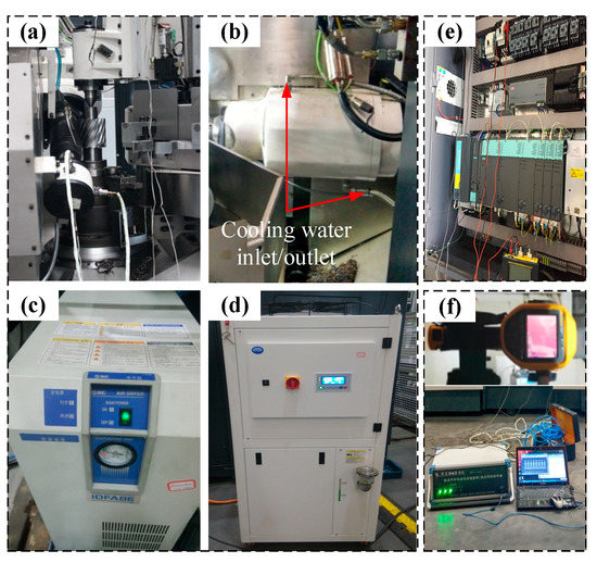
Figure 3.
Experimental test for validation: (a) Gear hobbing; (b) Motorized spindle; (c) Refrigerated air dryer; (d) Water-cooling machine; (e) Power measurement; (f) Temperature test platform

Table 1.
Relevant parameters of the motorized spindle system.
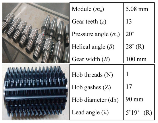
Figure 4.
Main parameters of machined gear and hob tool.
The power inputs of spindle motor at the non-cutting stage under different spindle speeds were measured and listed in Table 2. With the measured power values, several relation models between the motor power consumption and spindle speed were established using the second order polynomial function, linear function, and exponential function, as shown in Figure 5. It can be seen from Figure 5 that the second-order polynomial had the highest fitting degree (R2 = 0.9877), therefore, it was selected as the final expression function of spindle motor power consumption at the non-cutting stage. The cutting power for material removal of gear workpiece (as shown in Equation (2)) can be obtained referring our previous study [37].
Table 2.
Power input of spindle motor under different spindle speeds.
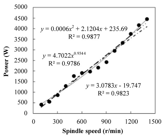
Figure 5.
Power measurements of spindle motor.
According to the technical constraints and actual production demand, the spindle speed was limited between 500 r/min and 1500 r/min. Considering the requirements of higher productivity and longer tool life, the lower and upper limits of axial feed rate were 1 mm/rev and 3 mm/rev, respectively. Based on the considerations of cooling capacity and economic cost, the limitations of water flow rate (from 10 kg/min to 90 kg/min) and compressed air temperature (from 5 °C to 25 °C) were determined.
4.1. Optimization Results
For solving the multi-objective optimization problem with NSGA-II, the initial parameters of the algorithm were determined as follows: population size was 100; mutation rate was 0.7; crossover rate was 0.05; iteration number was 200. Then, the multi-objective optimization model was solved and the Pareto frontiers of the trade-off of optimization objectives in an accepted level are presented in Figure 6. After calculation by TOPSIS algorithm, the optimization results under mono-objective and multi-objective optimization criteria could be obtained, as shown in Table 3.
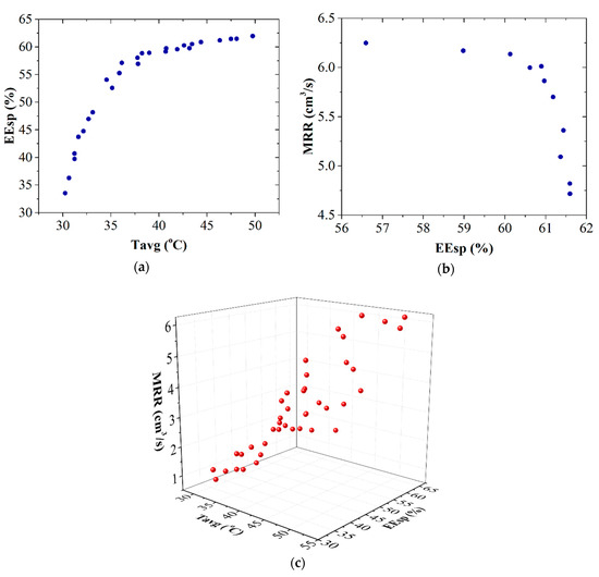
Figure 6.
Pareto frontiers under: (a) optimization with maximum EEsp and minimum Tavg; (b) optimization with maximum MRR and maximum EEsp and (c) optimization with maximum EEsp, maximum MRR, and minimum Tavg.
Table 3.
Optimization results.
As shown in Table 3, the optimization with maximizing EEsp led to the highest exergy efficiency (61.2%), however, it could not reach the excellent performances of thermal stability and productivity. Therefore, the comparision of optimization results under different combination of objective functions was carried out. It can be seen from Table 3 that, when the thermal constraint (spindle average temperature) was taken into consideration, both of the EEsp and MRR were reduced compared with the mono-objective optimization of EEsp. However, the Tavg was also reduced from 48.5 °C to 36.7 °C, which was very beneficial for thermal stability of motorized spindle. On the other hand, the exergy efficiency and material removal rate could be improved significantly under the multi-objective optimzation of maximum EEsp and maximum MRR. However, this optimization strategy led to higer spindle average temperature, which had a detrimental impact on thermal stability of the motorized spindle and finally deteriorate the machining accuracy.
In order to achieve the excellent comprehensive performance of the motorized spindle system, the optimization criteria of maximum EEsp, minimum Tavg, and maximum MRR were taken into consideration; this optimization realized a relative balance among these three objective functions, where the EEsp, MRR and Tavg are obtained as 57.4 %, 5.2 cm3/s and 42.0 °C, respectively. In order to evaluate the performance of the above optimization strategies, the evaluation criterion of Cli in TOPSIS algorithm was brought to calculate the Cl of the objective function values under different optimization conditions. The larger value of Cl meant the better performance of the optimization strategy [45]. It is illustrated in Table 3 that the largest value of Cli is up to 0.750, which meant that the best comprehensive performance of the motorized spindle system could be achieved by the multi-objective optimization with maximazing EEsp and MRR and minimizing Tavg.
Under the actual production of the given shaft gears, the main hobbing parameters and the calculated values of the objective function values are shown in the first row in Table 3. Compared with the actual production condition, the optimization with maximizing EEsp maximizing MRR and minimizing Tavg can greatly improve the productivity by 4 times and exergy efficiency by 18.6%, and maintain a reletively consistent spindle average temperature (as shown in Figure 7).
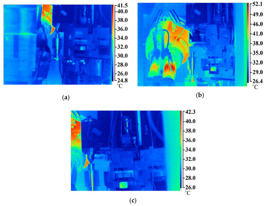
Figure 7.
Infrared thermogram under: (a) original condition; (b) optimization with maximum EEsp and (c) optimization with maximum EEsp, maximum MRR, and minimum Tavg.
4.2. Variations of Optimization Objectives
The variations of exergy efficiency, material removal rate and spindle average temperature along with the increase of decision variables are shown in Figure 8. As shown in Figure 8a,b, all objective values showed the uptrend with increasing cutting parameters (spindle speed n and feed rate fa). It can be concluded that larger cutting parameters should be selected to improve exergy efficiency and material removal rate. However, spindle average temperature was increased with the increases of spindle speed and feed rate because larger cutting parameters resulted in more heat generation of motorized spindle [37]. It was obvious that material removal rate did not change with the variations of mass flow rate of cooling water (ṁw) and compressed air temperature (Tca,in), as shown in Figure 8c,d, because these two decision variables had no influences on material removal rate. The spindle average temperature and exergy efficiency turned out to be descending with the increase of cooling water flow rate while increase was associated with the increase of compressed air temperature. This phenomenon can be explained in terms of the cooling capacity and energy consumption associated with the variations of cooling water flow rate and compressed air temperature.
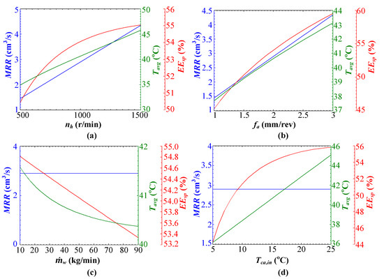
Figure 8.
Effects of: (a) spindle speed, (b) feed rate, (c) cooling water flow rate, and (d) compressed air temperature on EEsp, MRR, and Tavg.
5. Conclusions and Outlook
In the present paper, a new approach is proposed to investigate the energy optimization problem of the motorized spindle system of machine tools. Employing exergy analysis concept, a novel exergy efficiency model of motorized spindle system is developed by taking the energy consumption for material removal and thermal deformation control as useful energy consumption. Consequently, a multi-objective optimization model with the goal of maximization of exergy efficiency and material removal rate and minimization of spindle average temperature is proposed. A case study was presented to demonstrate the effectiveness of the proposed method and the optimal decision variables of the motorized spindle system are obtained and the optimization results are compared under mono- and multi-objective optimization conditions. It can be found that the mono-objective optimization with maximizing energy efficiency leads to an overall exergy efficiency of 61.2% and a material removal rate of 4.7 cm3/s while reaching the spindle average temperature of 48.5 °C. By performing the multi-objective optimization with the goal of maximization of energy efficiency and material removal rate and minimization of spindle average temperature leads to a solution which achieves an overall exergy efficiency of 57.4%, material removal rate of 5.2 cm3/s and spindle average temperature of 42.0 °C. This demonstrates that the proposed optimization method can discover a best solution achieving a reasonable trade-off among the three objectives.
Based on this study, future work to be considered is to reveal the potential relation between energy consumption and thermal deformation of motorized spindle. Moreover, an embedded software integrated into the NC system of machine tools will be also developed for industrial application of the proposed method.
Author Contributions
Conceptualization, B.L. (Benjie Li); methodology, B.L. (Benjie Li); software, B.L. (Benjie Li) and X.Y.; validation, B.L. (Benjie Li), X.Y., and B.L. (Binglin Li); formal analysis, B.L. (Benjie Li); investigation, B.L. (Benjie Li), X.Y., and B.L. (Binglin Li); resources, H.Z. and L.G.; data curation, B.L. (Benjie Li), X.Y., and B.L. (Binglin Li); writing—original draft preparation, B.L. (Benjie Li); writing—review and editing, X.Y. and H.Z.; visualization, B.L. (Benjie Li); supervision, H.Z. and L.G.; project administration, H.Z. and L.G.; funding acquisition, B.L. (Benjie Li), X.Y., L.G., and B.L. (Binglin Li). All authors have read and agreed to the published version of the manuscript.
Funding
This research was funded by the National Natural Science Foundation of China, grant number 51905059; the Young Science and Technology Innovation Team of SWPU, grant number 2019CXTD02; the Natural Science Foundation of Chongqing, grant number cstc2019jcyj-msxmX0205; and the Science and Technology Project of Deyang City, grant number 2020CKL006.
Acknowledgments
The authors gratefully acknowledge the Chongqing Machine Tool (Group) Co., Ltd. for its experimental tests support, and the reviewers and editors for their insightful comments.
Conflicts of Interest
The authors declare no conflict of interest.
References
- Duflou, J.R.; Sutherland, J.W.; Dornfeld, D.; Herrmann, C.; Jeswiet, J.; Kara, S.; Hauschild, M.; Kellens, K. Towards energy and resource efficient manufacturing: A processes and systems approach. Cirp. Ann. Manuf. Technol. 2012, 61, 587–609. [Google Scholar] [CrossRef]
- Jenny, L.D.; Carlos, O.M. Energy efficiency in discrete-manufacturing systems: Insights, trends, and control strategies. J. Manuf. Syst. 2019, 52, 131–145. [Google Scholar] [CrossRef]
- May, G.; Barletta, I.; Stahl, B.; Taisch, M. Energy management in production: A novel method to develop key performance indicators for improving energy efficiency. Appl. Energ. 2015, 149, 46–61. [Google Scholar] [CrossRef]
- Yoon, H.S.; Kim, E.S.; Kim, M.S.; Lee, J.Y.; Lee, G.B.; Ahn, S.H. Towards greener machine tools—A review on energy saving strategies and technologies. Renew. Sust. Energ. Rev. 2015, 48, 870–891. [Google Scholar] [CrossRef]
- Denkena, B.; Abele, E.; Brecher, C.; Dittrich, M.A.; Kara, S.; Mori, M. Energy efficient machine tools. Cirp. Ann. Manuf. Technol. 2020, 69, 646–667. [Google Scholar] [CrossRef]
- Kroll, L.; Blau, P.; Wabner, M.; Frie, U.; Eulitz, J.; Kl?rner, M. Lightweight components for energy-efficient machine tools. Cirp. J. Manuf. Sci. Technol. 2011, 4, 148–160. [Google Scholar] [CrossRef]
- Yi, Q.; Li, C.B.; Ji, Q.Q.; Zhu, D.G.; Jin, Y.; Li, L.L. Design optimization of lathe spindle system for optimum energy efficiency. J. Clean Prod. 2020, 250. in press. [Google Scholar] [CrossRef]
- Neugebauer, R.; Wabner, M.; Rentzsch, H.; Ihlenfeldt, S. Structure principles of energy efficient machine tools. Cirp. J. Manuf. Sci. Technol. 2011, 4, 136–147. [Google Scholar] [CrossRef]
- Kara, S.; Li, W. Unit process energy consumption models for material removal processes. Cirp. Ann. Manuf. Technol. 2011, 60, 37–40. [Google Scholar] [CrossRef]
- Lv, J.X.; Tang, R.Z.; Tang, W.C.J.; Jia, S.; Liu, Y.; Cao, Y.L. An investigation into methods for predicting material removal energy consumption in turning. J. Clean Prod. 2018, 193, 128–139. [Google Scholar] [CrossRef]
- Balogun, V.A.; Edem, I.F.; Adekunle, A.A.; Mativenga, P.T. Specific energy based evaluation of machining efficiency. J. Clean Prod. 2016, 116, 187–197. [Google Scholar] [CrossRef]
- Albertelli, P. Energy saving opportunities in direct drive machine tool spindles. J. Clean Prod. 2017, 165, 855–873. [Google Scholar] [CrossRef]
- Yoon, H.S.; Singh, E.; Min, S. Empirical power consumption model for rotational axes in machine tools. J. Clean Prod. 2018, 196, 370–381. [Google Scholar] [CrossRef]
- Okwudire, C.; Rodgers, J. Design and control of a novel hybrid feed drive for high performance and energy efficient machining. Cirp. Ann. Manuf. Technol. 2013, 62, 391–394. [Google Scholar] [CrossRef]
- Gao, M.D.; Li, L.; Wang, Q.Y.; Liu, C.H. Energy Efficiency and Dynamic Analysis of a Novel Hydraulic System with Double Actuator. Int. J. Precis Eng. Manuf. Green Technol. 2020, 7, 643–655. [Google Scholar] [CrossRef]
- Kolar, M.; Vyroubal, J.; Smolik, J. Analytical approach to establishment of predictive models of power consumption of machine tools’ auxiliary units. J. Clean Prod. 2016, 137, 361–369. [Google Scholar] [CrossRef]
- Shang, Z.D.; Gao, D.; Jiang, Z.P.; Lu, Y. Towards less energy intensive heavy-duty machine tools: Power consumption characteristics and energy-saving strategies. Energy 2019, 178, 263–276. [Google Scholar] [CrossRef]
- Xiao, Q.G.; Li, C.B.; Tang, Y.; Pan, J.; Yu, J.; Chen, X.Z. Multi-component energy modeling and optimization for sustainable dry gear hobbing. Energy 2019, 187. in press. [Google Scholar] [CrossRef]
- Shin, S.J.; Woo, J.; Rachuri, S. Energy efficiency of milling machining: Component modeling and online optimization of cutting parameters. J. Clean Prod. 2017, 161, 12–29. [Google Scholar] [CrossRef]
- Xiao, Q.G.; Li, C.B.; Tang, Y.; Li, L.L.; Li, L. A knowledge-driven method of adaptively optimizing process parameters for energy efficient turning. Energy 2019, 166, 142–156. [Google Scholar] [CrossRef]
- Mori, K.; Bergmann, B.; Kono, D.; Denkena, B.; Matsubara, A. Energy efficiency improvement of machine tool spindle cooling system with on–off control. Cirp. J. Manuf. Sci. Technol. 2019, 25, 14–21. [Google Scholar] [CrossRef]
- Wójcicki, J.; Leonesio, M.; Bianchi, G. Integrated energy analysis of cutting process and spindle subsystem in a turning machine. J. Clean Prod. 2018, 170, 1459–1472. [Google Scholar] [CrossRef]
- Liu, F.; Xie, J.; Liu, S. A method for predicting the energy consumption of the main driving system of a machine tool in a machining process. J. Clean Prod. 2015, 105, 171–177. [Google Scholar] [CrossRef]
- Lv, J.X.; Tang, R.Z.; Tang, W.C.J.; Liu, Y.; Zhang, Y.F.; Jia, S. An investigation into reducing the spindle acceleration energy consumption of machine tools. J. Clean Prod. 2017, 143, 794–803. [Google Scholar] [CrossRef]
- Abele, E.; Sielaff, T.; Schiffler, A.; Rothenbücher, S. Analyzing energy consumption of machine tool spindle units and identification of potential for improvements of efficiency. In Glocalized Solutions for Sustainability in Manufacturing; Springer: Berlin/Heidelberg, Germany, 2011; pp. 280–285. [Google Scholar] [CrossRef]
- Wennemer, M.; Brecher, C.; Klatte, M.; Jasper, D. Thermo Energetic Design of Machine Tools and Requirements for Smart Fluid Power Systems. In Proceedings of the 10th International Fluid Power Conference, Dresden, Germany, 8–10 March 2016; pp. 177–194. [Google Scholar]
- Denkena, B.; Helmecke, P.; Hülsemeyer, L. Energy Efficient Machining with Optimized Coolant Lubrication Flow Rates. Procedia Cirp. 2014, 24, 25–31. [Google Scholar] [CrossRef]
- Zhao, G.Y.; Liu, Z.Y.; He, Y.; Cao, H.J.; Guo, Y.B. Energy consumption in machining: Classification, prediction, and reduction strategy. Energy 2017, 133, 142–157. [Google Scholar] [CrossRef]
- Bossmanns, B.; Tu, J.F. A Power Flow Model for High Speed Motorized Spindles-Heat Generation Characterization. J. Manuf. Sci. Eng. 2001, 123, 494–505. [Google Scholar] [CrossRef]
- Grama, S.N.; Mathur, A.; Badhe, A.N. A model-based cooling strategy for motorized spindle to reduce thermal errors. Int. J. Mach. Tool Manuf. 2018, 132, 3–16. [Google Scholar] [CrossRef]
- NSK. Technical Manual of NSK Rolling Bearings; NSK Ltd.: Tokyo, Japan, 2008. [Google Scholar]
- Li, K.Y.; Luo, W.J.; Hong, X.H.; Wei, S.J.; Tsai, P.H. Enhancement of Machining Accuracy Utilizing Varied Cooling Oil Volume for Machine Tool Spindle. IEEE Access 2020, 8, 28988–29003. [Google Scholar] [CrossRef]
- Pusavec, F.; Krajnik, P.; Kopac, J. Transitioning to sustainable production—Part I: Application on machining technologies. J. Clean Prod. 2010, 18, 174–184. [Google Scholar] [CrossRef]
- Zhu, L.B.; Cao, H.J.; Huang, H.H.; Yang, X. Exergy analysis and multi-objective optimization of air cooling system for dry machining. Int. J. Adv. Manuf. Technol. 2017, 93, 3175–3188. [Google Scholar] [CrossRef]
- Li, B.J.; Cao, H.J.; Hon, B.; Liu, L.; Gao, X. Exergy-based Energy Efficiency Evaluation Model for Machine Tools Considering Thermal Stability. Int. J. Precis Eng. Manuf. Green Technol. 2020, in press. [Google Scholar] [CrossRef]
- Cengel, Y.A.; Boles, M.A. Thermodynamics: An. Engineering Approach, 7th ed.; McGraw-Hill Education: New York, NY, USA, 2010. [Google Scholar]
- Li, B.J.; Cao, H.J.; Yang, X.; Jafar, S.; Zeng, D. Thermal energy balance control model of motorized spindle system enabling high-speed dry hobbing process. J. Manuf. Process. 2018, 35, 29–39. [Google Scholar] [CrossRef]
- Bergman, T.L.; Lavine, A.S.; Incropera, F.P.; Dewitt, D.P. Fundamentals of Heat and Mass Transfer, 7th ed.; John Wiley & Sons, Inc.: Hoboken, NJ, USA, 2011. [Google Scholar]
- Liu, J.; Chen, X. Dynamic design for motorized spindles based on an integrated model. Int. J. Adv. Manuf. Technol. 2014, 71, 1961–1974. [Google Scholar] [CrossRef]
- Bossmanns, B.; Tu, J.F. A thermal model for high speed motorized spindles. Int. J. Mach. Tool Manuf. 1999, 39, 1345–1366. [Google Scholar] [CrossRef]
- Deb, K.; Pratap, A.; Agarwal, S.; Meyarivan, T. A fast and elitist multiobjective genetic algorithm: NSGA-II. IEEE Trans. Evol. Comput. 2002, 6, 182–197. [Google Scholar] [CrossRef]
- Lin, Y.K.; Yeh, C.T. Multi-objective optimization for stochastic computer networks using NSGA-II and TOPSIS. Eur. J. Oper. Res. 2012, 218, 735–746. [Google Scholar] [CrossRef]
- Navidbakhsh, M.; Shirazi, A.; Sanaye, S. Four E analysis and multi-objective optimization of an ice storage system incorporating PCM as the partial cold storage for air-conditioning applications. Appl. Eng. 2013, 58, 30–41. [Google Scholar] [CrossRef]
- Yue, Z.L. A method for group decision-making based on determining weights of decision makers using TOPSIS. Appl. Math. Model. 2011, 35, 1926–1936. [Google Scholar] [CrossRef]
- Shirazi, A.; Najafi, B.; Aminyavari, M.; Rinaldi, F.; Taylor, R.A. Thermal-economic-environmental analysis and multi-objective optimization of an ice thermal energy storage system for gas turbine cycle inlet air cooling. Energy 2014, 69, 212–226. [Google Scholar] [CrossRef]
Publisher’s Note: MDPI stays neutral with regard to jurisdictional claims in published maps and institutional affiliations. |
© 2020 by the authors. Licensee MDPI, Basel, Switzerland. This article is an open access article distributed under the terms and conditions of the Creative Commons Attribution (CC BY) license (http://creativecommons.org/licenses/by/4.0/).