Abstract
Sintering and carbon deposition are the two main ways to deactivate Ni-based catalysts during methane reforming. Herein, a stable Ni-CeO2/SiO2(CSC) catalyst was prepared by a one-step colloidal solution combustion method (CSC) and used for dry reforming of methane. In the catalyst, the small Ni particles were confined by CeO2 particles and highly dispersed on the surface of SiO2, forming a spatial confinement structure with a rich Ni-CeO2 interface in the catalyst. The Ni-CeO2/SiO2(CSC) catalyst prepared by the one-step CSC method exhibited superior activity at 700 °C during dry reforming of methane, and the performance of the catalyst was stable after 20 h of reaction with only a small amount of carbon deposition present (1.8%). Due to the spatial confinement effect, Ni was stable and less than 5 nm during reaction. The small Ni particle size and rich Ni-CeO2 interface reduced the rate of carbon deposition. This colloidal combustion method could be applied to prepare stable metal-based catalysts with rich metal–oxide interfaces for high-temperature reactions.
1. Introduction
Due to abundant natural gas reserves, dry reforming of methane (DRM) has become a key research topic in recent years [1,2,3]. This reaction can produce H2 and CO, while consuming CH4 and CO2 greenhouse gasses. Supported metal catalysts have been widely investigated for DRM. The precious metals Pt [4], Pd [5], Ru [6,7], and Rh [8] have excellent catalytic performances in DRM reactions, but their high prices limit their industrial use. Inexpensive Ni-based catalysts also have high activity, but they are prone to carbon deposition and sintering [9,10].
The size of Ni nanoparticles can greatly affect carbon deposition during DRM. Small Ni particles are resistant to carbon deposition during DRM [11]. However, small nickel particles are easily sintered during the DRM reaction at high temperature, and the formation of large nickel particles leads to carbon deposition. Small and stable Ni particles are highly desired as Ni-based DRM catalysts [12]. For Ni-based DRM catalysts, the support, promoter, and preparation methods can affect the size and thermal stability of Ni nanoparticles [1,2]. In order to inhibit sintering of Ni nanoparticles at a high temperature, confined catalysts, such as core-shell Ni@SiO2 [13] and embedded Ni/SBA-15 [12], have been designed and used for DRM. Wang et al. [13] synthesized core-shell structured Ni@SiO2 catalysts with small-sized Ni nanoparticles (about 5 nm) by microemulsion method, which are stable during high temperature DRM. Recently, Peng et al. [14] had proposed a surface spatial confinement strategy to design high-performing catalysts for the dry reforming of methane (DRM). Active Ni nanoparticles were confined on the surface of a dendritic mesoporous silica, and the catalyst was stable during 145 h time-on-stream at 700 °C.
Due to excellent redox properties, CeO2 has been widely used in Ni-based DRM catalysts [12,15,16,17]. Oxygen vacancies in CeO2 and Ni-CeO2 interfaces can facilitate carbon gasification, help reduce carbon formation, and improve the stability of nickel-based catalysts [16]. Yan et al. reported on a Ni/CeO2-SiO2 catalyst, including CeO2 in close contact with Ni nanoparticles, which was prepared with a plasma decomposed method, and the catalyst was highly efficient and stable during DRM [17]. The excellent performance of the catalyst was due to the greater Ni-CeO2 interface. Small Ni nanoparticles in close contact with small CeO2 nanoparticles can form a greater Ni-CeO2 interface. However, preparation of a stable catalyst with close contacted Ni and CeO2 particles, both less than 5 nm, is still a challenge.
Colloidal solution combustion (CSC) is a facile strategy to prepare metal-based catalysts with plenty of metal–oxide interfaces [18,19,20,21]. Ni-based catalyst with Ni particles encapsulated with the amorphous La2O3 had been prepared with the CSC method and used for DRM [22]. CeO2 based catalysts prepared with CSC method, such as Co-CeO2 [19], had shown good stability in reverse water–gas shift reaction. In order to inhibit Ni sintering and carbon deposition of Ni-based catalysts during DRM, a Ni-CeO2/SiO2(CSC) catalyst with spatial confinement and interfacial synergism was prepared by the one-step CSC method in this work. Its DRM performance was compared with Ni-CeO2(SC) and Ni-CeO2/SiO2(IM) prepared by solution combustion (SC) and impregnation (IM) methods, respectively.
2. Experimental Methods
2.1. Synthesis of Catalysts
The Ni-CeO2/SiO2(CSC) catalyst was prepared by colloidal solution combustion (CSC). In total, 2.272 g Ce(NO3)2·6H2O, 0.494 g Ni(NO3)2·6H2O, 1.26 mL colloidal SiO2 (LUDOX TMA, Sigma-Aldrich, Saint Louis, MI, USA; 34 wt. %, diameter of 22 nm), and 0.6 g glycine were added into 6.3 mL of water to form a solution. In the solution, nitrate was used as an oxidant and glycine as a fuel. The solution was heated on a heating plate at 230 °C, which was then dried to induce combustion. The obtained powder was calcinated at 600 °C for 4 h, and the Ni-CeO2/SiO2(CSC) catalyst was obtained. The theoretical weight contents of nickel and cerium were 6.3% and 56.7%, respectively.
For comparison, the Ni-CeO2/SiO2(IM) catalyst was prepared by an impregnation method (IM). The preparation process was similar to that of the Ni-CeO2/SiO2(CSC) catalyst, except that glycine was not added.
The Ni-CeO2(SC) catalyst was prepared by solution combustion (SC). The preparation process was similar to that of the Ni-CeO2/SiO2(CSC) catalyst, except that colloidal SiO2 was not added. The theoretical weight content of nickel was 6.3%.
2.2. Characterization of Catalysts
N2 adsorption isotherms were obtained using an Autosorb-iQ analyzer at −196 °C. The sample was degassed for 3h at 300 °C before testing. The specific surface area (SBET) was calculated using the Brunauer–Emmett–Teller (BET) method. The total pore volume and pore size distribution were obtained using the Barrett–Joyner–Halenda (BJH) method. Nickel content in the catalyst was determined by atomic absorption spectroscopy (AAS, TAS-990, Persee Analytical Instruments, Beijing, China).
The phase structures of the catalysts were characterized by X-ray diffraction (XRD) using a MiniFlex6 diffractometer with Cu Kα radiation (λ = 0.15406 nm) operated at 40 kV and 15 mA. The 2θ angle was scanned from 20 to 80° with a scan rate of 10° min−1. Transmission electron microscopy (TEM) images were characterized with a Tecnai G2 F20 microscope using a 200 kV accelerating voltage.
H2 temperature-programmed reduction (H2-TPR) was conducted on a TP-5080 adsorption apparatus with a thermal conductivity detector (TCD). Fifty milligrams of catalyst was pretreated in Ar at 400 °C for 25 min and then cooled to room temperature. Subsequently, the catalyst was reduced from room temperature to 900 °C in 5% H2/Ar at a heating rate of 10 °C min−1.
CO2 temperature-programmed desorption (CO2-TPD) was performed in a fixed-bed quartz reactor. Fifty milligrams of catalyst was reduced in 20% H2/N2 at 700 °C for 0.5 h. CO2 adsorption was conducted at room temperature °C using pure CO2 for 1 h. Then, the catalyst was purged with N2 for 2h. Finally, the sample was heated form room temperature to 800 °C at a heating rate of 10 °C /min, and CO2 desorption signal was detected by a mass spectrometer (HPR-20, Hiden Analytical Ltd., Warrington, UK)
X-ray photoelectron spectroscopy (XPS) was detected on a Thermo Scientific ESCALAB 250Xi spectrometer (Al Kα). Thermogravimetry (TG) and differential thermal analysis (DTA) were conducted on an HCT-1 thermal analyzer, under air flow, from room temperature to 900 °C at a temperature ramping of 10 °C min−1.
2.3. Catalytic Performance
Catalytic tests were performed in a fixed-bed quartz reactor at 700 °C and 0.1 MPa feed gas (CO2/CH4/Ar= 3:3:14) at a flow rate of 100 mL min−1. Before the reaction, 0.050 g of catalyst was heated to 700 °C at a heating rate of 10 °C min−1 in 20% H2/Ar (50 mL min−1) and reduced at that temperature for 1 h. The outlet gas was analyzed by two online gas chromatographs (SP-3420 and G5) equipped with TDX-01 columns and TCD detectors.
3. Results and Discussion
3.1. Characterization of Fresh and Reduced Catalysts
Table 1 lists the physical properties of fresh catalysts. For the Ni-CeO2/SiO2(CSC) and Ni-CeO2/SiO2(IM) catalyst, the Ni loadings determined by AAS measurement are close to the theoretical value. The SBET of Ni-CeO2/SiO2(CSC) and Ni-CeO2/SiO2(IM) were 63.5 and 54.6 m2/g, respectively, while the SBET of Ni-CeO2(SC) catalyst was only 7.0 m2/g. The SBET of the catalyst prepared by solution combustion method was usually low [23], which is not conducive to the high dispersion of active catalyst components. The pore volume of the Ni-CeO2(SC) catalyst was significantly smaller than that of the other two catalysts. Our result suggests the addition of colloidal SiO2 can increase the SBET and pore volume of the Ni-CeO2(SC) catalyst.

Table 1.
Physical properties of the fresh catalysts.
The nitrogen adsorption–desorption isotherms and pore size distributions are shown in the Figure 1. As shown in Figure 1a, the isotherms of Ni-CeO2-SiO2(IM) and Ni-CeO2-SiO2(CSC) had hysteresis loop, indicating the mesoporous structures in the two catalysts. The hysteresis loop of the Ni-CeO2-SiO2(IM) was more evident, corresponding with an obviously pore size distribution in the range of 5–25 nm in Figure 1b. As shown in Figure 1b, there were obvious micropores smaller than 2 nanometers in the Ni-CeO2-SiO2(IM) and Ni-CeO2-SiO2(CSC) catalysts, which should be attributed to the using of SiO2. On the contrary, there were no obvious micropores and mesoporous in Ni-CeO2(SC) catalyst, which results in lower specific surface area of the catalyst.
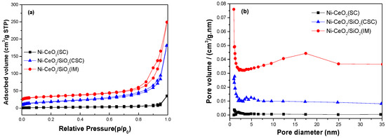
Figure 1.
(a) N2 adsorption–desorption isotherms and (b) the pore size distributions of Ni-CeO2-SiO2(IM), Ni-CeO2-SiO2(CSC) and Ni-CeO2(SC) catalysts.
The fresh and reduced catalysts were characterized by X-ray diffraction (XRD), and the results are shown in Figure 2. From Figure 2a, the fresh Ni-CeO2 (SC) catalyst clearly showed typical diffraction peaks of CeO2 and NiO. For Ni-CeO2-SiO2(IM), the diffraction peak of CeO2 was broader than that of the Ni-CeO2 (SC) catalyst, indicating the crystal size of CeO2 in the Ni-CeO2-SiO2(IM) catalyst is smaller than that of the Ni-CeO2(SC) catalyst. Obvious NiO peaks can also be observed in the XRD pattern of the Ni-CeO2(SC) catalyst. However, for the Ni-CeO2-SiO2(CSC) catalyst, the diffraction peaks of NiO disappeared, and the diffraction peak of CeO2 was very weak. As listed in Table 1, in the Ni-CeO2 (SC) and Ni-CeO2/SiO2(IM) catalysts, the crystal sizes of NiO were about 15 nm, and the crystal sizes of CeO2 were 37.9 and 6.1 nm, respectively. For the Ni-CeO2-SiO2(CSC) catalyst, the diffraction peaks of CeO2 and NiO were too weak and could not be used for calculating crystal size, suggesting the particle sizes of NiO and CeO2 in the Ni-CeO2-SiO2(CSC) catalyst were small.
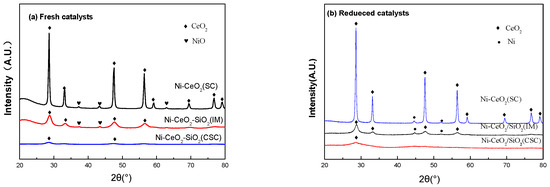
Figure 2.
X-ray diffraction (XRD) patterns of (a) fresh and (b) reduced catalysts.
As shown in Figure 2b, the diffraction peak of NiO disappeared, and the diffraction peaks of Ni appeared at 44.5° and 52.0° in the reduced Ni-CeO2 (SC) and Ni-CeO2/SiO2(IM) catalysts. As shown in Table 2, the Ni particle sizes of the reduced Ni-CeO2 (SC) and Ni-CeO2/SiO2(IM) catalysts were larger than those of the NiO in the fresh catalysts, indicating that Ni was sintered during the reduction process. The absence of Ni diffraction peaks in the reduced Ni-CeO2/SiO2(CSC) catalyst indicates that Ni was highly dispersed in the reduced catalyst.
Table 2.
Crystal size of the reduced catalysts.
Transmission electron microscopy images of fresh catalysts are shown in Figure 3. Figure 3a illustrates that the nanoparticles in the Ni-CeO2(SC) catalyst were larger than 10 nm. In the Ni-CeO2/SiO2(IM) catalyst, the nanoparticles of NiO and CeO2 agglomerated on the SiO2 support, and some of the SiO2 support was not loaded with NiO and CeO2 nanoparticles, as shown in Figure 3b. In contrast, Figure 3c,d illustrates NiO and CeO2 nanoparticles less than 5 nm were highly dispersed on silica nanospheres in Ni-CeO2/SiO2(CSC). In addition, small NiO particles were in close contact with CeO2 nanoparticles in the catalyst, which resulted in the NiO particle being spatially confined by CeO2 particles. Spatial confinement should inhibit the sintering of nanoparticles during high-temperature reduction reactions and improve the thermal stability of catalysts. The results show that CSC cannot only make NiO and CeO2 highly dispersed on SiO2, but it can also confine NiO by CeO2. The spatially confined structure can ensure abundant Ni-CeO2 interfaces in the catalyst after reduction, which will be beneficial to inhibit carbon deposition during DRM.
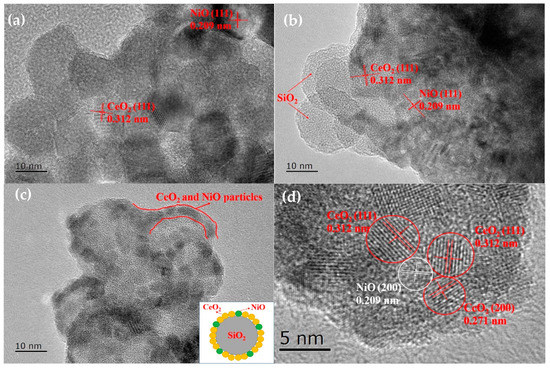
Figure 3.
Transmission electron microscopy images of fresh catalyst: (a) Ni-CeO2(SC); (b) Ni-CeO2/SiO2(IM); and (c, d) Ni-CeO2/SiO2(CSC).
The reduction performance of the catalysts was measured by H2 temperature-programmed reduction (H2-TPR). As shown in Figure 4, the reduction peak at about 395 °C of the Ni-CeO2(SC) catalyst was ascribed to the reduction in free NiO particles, and the reduction peak at 800 °C was ascribed to the reduction in bulk CeO2 [24]. For Ni-CeO2-SiO2(IM), the two reduction peaks were similar to that of the Ni-CeO2(SC) catalyst, indicating that NiO particles weakly (or not at all) interacted with CeO2 and SiO2 in the two catalysts. In contrast, a broad reduction peak at 200–600 °C appeared in the Ni-CeO2-SiO2(CSC) catalyst. Hydrogen consumption below 300 °C was ascribed to the reduction in adsorbed oxygen species in the oxygen vacancies, which were generated by the formation of the NixCe1-xOy solid solution [25,26]. Hydrogen consumption above 400 °C was due to the reduction in NiO, which strongly interacted with CeO2 and SiO2 [26,27]. This strong interaction always results in a higher reduction temperature for NiO [28]. Combined with XRD and TEM, these results indicate small NiO particles strongly interacted with CeO2 and SiO2 in the Ni-CeO2/SiO2(CSC) catalyst, while the large NiO particle weakly (or not at all) interacted with CeO2 and SiO2 in the Ni-CeO2(SC) and Ni-CeO2/SiO2(IM) catalysts.
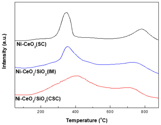
Figure 4.
H2 temperature-programmed reduction (H2-TPR) profiles of the Ni-CeO2(SC), Ni-CeO2/SiO2(IM) and Ni-CeO2/SiO2(CSC) catalysts.
In order to determine the surface basic sites of the Ni-CeO2/SiO2(CSC) and Ni-CeO2/SiO2(IM) catalysts, CO2-TPD tests were performed. As shown in Figure 5, the Ni-CeO2/SiO2(CSC) catalyst displayed a larger TPD desorption peak than the Ni-CeO2/SiO2(IM) catalyst, indicating that the surface of Ni-CeO2/SiO2(CSC) has more basic sites that can adsorb and activate CO2.
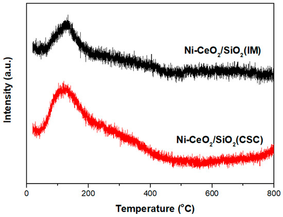
Figure 5.
CO2 temperature-programmed desorption (CO2-TPD) profiles of the Ni-CeO2/SiO2(CSC) and Ni-CeO2/SiO2(IM) catalysts.
XPS analysis was carried out for investigate surface structure of the catalysts. XPS spectra of Ce 3d are shown in Figure 6, which could be deconvoluted into ten peaks. The peaks of v, v2, v3, u, u2, and u3 were attributed to the Ce4+ species, and the peaks of v°, v1, u°, and u1 were attributed to the Ce3+ species [29]. Based on the peaks area of Ce 3+ species to the total Ce 3+ and Ce4+ species, the relative content of Ce 3+ was calculated, and the results are listed in Table 3. The catalyst showed the highest Ce3+ surface content (26.2%), indicating the formation of most oxygen vacancies in the ceria surface. According to literature, the small CeO2 size or formation of NixCe1−xOy solid solution can increase the formation of oxygen vacancies, leading to a higher Ce3+ surface content. The XPS results was consistent with the above XRD and TPR results.
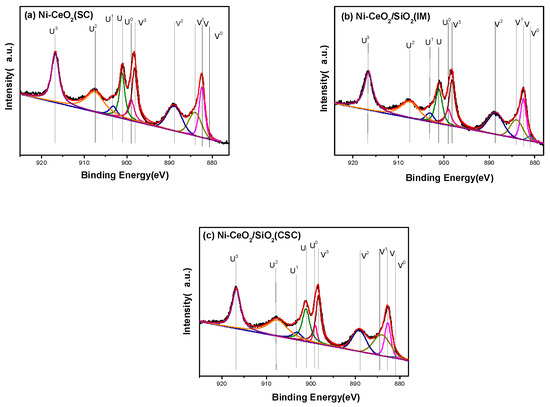
Figure 6.
Ce 3d X-ray photoelectron spectroscopy (XPS) spectra of the catalysts: (a) Ni-CeO2 (SC); (b) Ni-CeO2/SiO2(IM); (c) Ni-CeO2/SiO2(CSC).
Table 3.
Surface atomic ratio determined from XPS analysis for fresh catalysts.
As listed in Table 3, compared with Ni-CeO2/SiO2(IM), the Ni-CeO2/SiO2(CSC) showed higher surface atomic ratios of Ni and Ni/Ce. The higher surface atomic ratio of Ni indicates that more Ni surface was exposed in the Ni-CeO2/SiO2(CSC) catalyst. Combined with XRD and TEM results, the higher surface atomic ratios of Ni in the Ni-CeO2/SiO2(CSC) catalyst should be attributed to the small NiO particles. The higher surface atomic ratio of Ni/Ce in the Ni-CeO2/SiO2(CSC) indicates that, although the nickel particles were in close contact with CeO2, they were not covered by CeO2. Combining the XPS and TEM results, it can be concluded that the Ni-CeO2/SiO2(CSC) catalyst had abundant Ni surface and Ni-CeO2 interface at the same time.
3.2. Catalytic Performance
The catalytic performances are shown in Figure 7. As shown in Figure 7a,b, CO2 conversion was higher than CH4 conversion, which was due to the reverse water–gas shift reaction [30]. As shown in Figure 7, methane and CO2 conversions followed the sequence Ni-CeO2/SiO2(CSC) > Ni-CeO2/SiO2(IM) > Ni-CeO2(SC). As for Ni-CeO2/SiO2(IM), methane conversion decreased from 65% to 57% within 20 h. Methane conversion of Ni-CeO2 (SC) decreased from 53 to 36% within 20 h. Methane and CO2 conversions of Ni-CeO2/SiO2(CSC) were stable at about 77 and 85% during 20 h, and the H2/CO value of the catalyst was about 0.95. The results indicate the Ni-CeO2/SiO2(CSC) catalyst had better activity and stability than the Ni-CeO2 (SC) and Ni-CeO2/SiO2(IM) catalysts in DRM. The excellent catalytic performance of Ni-CeO2/SiO2(CSC) could be attributed to the spatial confinement of small Ni particles and the rich Ni-CeO2 interface. Spatial confinement can inhibit the sintering of Ni particles, which can improve the stability of Ni based catalyst during DRM. In the Ni-CeO2 interface, small Ni particles are in close contact with the reactive oxygen species of CeO2. The carbon species, produced by CH4 dissociation on Ni, can react with reactive oxygen species of CeO2 to form CO, preventing the carbon deposition [17].
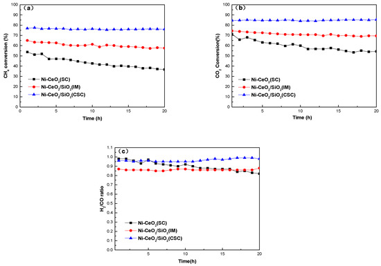
Figure 7.
Catalyst tests of the Ni-CeO2(SC), Ni-CeO2/SiO2(IM), and Ni-CeO2/SiO2(CSC) catalysts at 700 °C. (a) CH4 conversions, (b) CO2 conversions and (c) H2/CO ratio.
3.3. Characterization of the Used Catalyst
XRD patterns of the catalysts after 20 h of DRM are shown in Figure 8. The used Ni-CeO2(SC) and Ni-CeO2/SiO2(IM) catalysts also showed obvious Ni peaks. However, for the Ni-CeO2/SiO2(CSC) catalyst, no obvious Ni peak could be observed, indicating the small Ni particles were stable during DRM at 700 °C. In the used Ni-CeO2(SC) and Ni-CeO2/SiO2(IM) catalysts, there was a weak peak at 26.3° corresponding to graphite carbon [22,30], indicating carbon deposition formed on the two catalysts.
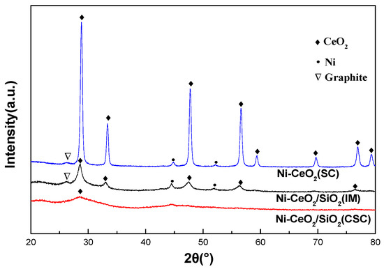
Figure 8.
XRD patterns of the used Ni-CeO2(SC), Ni-CeO2/SiO2(IM), and Ni-CeO2/SiO2(CSC) catalysts.
The used catalysts were characterized by transmission electron microscopy (TEM). There were a large number of carbon nanotubes on the used Ni-CeO2(SC) and Ni-CeO2/SiO2(IM) catalysts, as shown in Figure 9a,b. Ni particles were found on the top or in the middle of carbon nanotubes. Carbon deposition is affected by Ni particle size and is easily generated on Ni particles larger than 7 nm [11]. Extensive carbon deposition on these two catalysts was due to the large Ni particle size in these catalysts. On the contrary, only a few carbon nanotubes were found on the used Ni-CeO2/SiO2(CSC) catalyst (Figure 9c), which indicates that the Ni-CeO2/SiO2(CSC) catalyst was better at reducing carbon formation during DRM compared to the other two catalysts. As shown in Figure 9d, after the DRM reaction for 20 h, small Ni and CeO2 particles were uniformly coated on the surface of spherical SiO2 nanoparticles, suggesting that small Ni particles in the Ni-CeO2/SiO2(CSC) catalyst are stable in the high-temperature reaction.
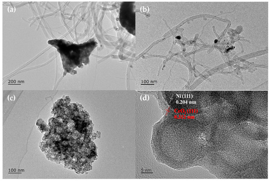
Figure 9.
Transmission electron microscopy images of the used catalysts: (a) Ni-CeO2(SC), (b)Ni-CeO2/SiO2(IM), and (c,d) Ni-CeO2/SiO2(CSC).
The used catalysts were characterized by thermogravimetry (TG) and differential thermal analysis (DTA), and the results are shown in Figure 10. In Figure 10a, the weight loss below 200 °C was attributed to the desorption of water, while the weight increase between 200 and 500 °C was attributed to the oxidation of Ni. Between 500 and 700 °C in Figure 10a, weight loss occurred in each catalyst, which was ascribed to the oxidation of deposited carbon, while the corresponding exothermic peak can be seen in the DTA profile (Figure 10b). As shown in Figure 10a, the amount of carbon deposited on the used Ni-CeO2/SiO2(IM) and Ni-CeO2(SC) catalysts was 11.1 and 3.9%, while that of the used Ni-CeO2/SiO2(CSC) catalyst was only 1.8%. The results indicate that the Ni-CeO2/SiO2(CSC) catalyst has an excellent anti-carbon deposition ability, which is consistent with the TEM results.
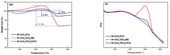
Figure 10.
Characterizations of thermogravimetry (TG) (a) and differential thermal (DTA) (b) of the used catalysts.
Combining the catalytic tests and various characterizations, the Ni-CeO2/SiO2(CSC) catalyst exhibited better carbon resistance ability and stability during DRM, which can be attributed to the spatial confinement structure in which small Ni particles are in close contact with small CeO2 particles on the SiO2 surface. On the one hand, small Ni particles are beneficial to reducing the formation of carbon deposits in the reaction. On the other hand, close contact between nickel and cerium oxide particles can form a rich Ni-CeO2 interface, which is also conducive to the gasification of carbon species and inhibition of carbon deposition [17]. In addition, spatial confinement can inhibit Ni sintering and improve the stability of Ni particles.
4. Conclusions
In this paper, Ni-CeO2(SC), Ni-CeO2/SiO2(IM), and Ni-CeO2/SiO2(CSC) catalysts were prepared and used for the DRM reaction. The Ni-CeO2(SC) and Ni-CeO2/SiO2(IM) catalysts, prepared by solution combustion and impregnation methods, respectively, had large Ni particles and resulted in large amounts of carbon deposited during the DRM reaction. The Ni-CeO2/SiO2(CSC) catalyst prepared by one-step CSC had a spatial confinement structure with small Ni particles confined by CeO2. Due to the spatial confinement structure, the Ni-CeO2/SiO2(CSC) catalyst exhibited high stability and limited carbon deposition during the DRM reaction.
Author Contributions
Conceptualization, L.W.; data curation, C.Z.; formal analysis, C.Z., R.Z., H.L., and L.W.; funding acquisition, L.W.; investigation, C.Z.; writing—original draft, C.Z. and L.W.; writing—review and editing, C.Z., R.Z., H.L., Q.W., D.G., L.M., H.T., S.C., and L.W. All authors have read and agreed to the published version of the manuscript.
Funding
This research was funded by the Fundamental Research Funds for Zhejiang Provincial Universities and Research Institutes (No. 2019JZ00003, No. 2019J00005) and the Science and Technology Foundation of Zhoushan (No. 2018C21013).
Conflicts of Interest
The authors declare no conflict of interest.
References
- Abdulrasheed, A.; Jalil, A.A.; Gambo, Y.; Ibrahim, M.; Hambali, H.U.; Shahul Hamid, M.Y. A review on catalyst development for dry reforming of methane to syngas: Recent advances. Renew. Sustain. Energy Rev. 2019, 108, 175–193. [Google Scholar] [CrossRef]
- Jang, W.-J.; Shim, J.-O.; Kim, H.-M.; Yoo, S.-Y.; Roh, H.-S. A review on dry reforming of methane in aspect of catalytic properties. Catal. Today 2019, 324, 15–26. [Google Scholar] [CrossRef]
- Aramouni, N.A.K.; Touma, J.G.; Tarboush, B.A.; Zeaiter, J.; Ahmad, M.N. Catalyst design for dry reforming of methane: Analysis review. Renew. Sustain. Energy Rev. 2018, 82, 2570–2585. [Google Scholar] [CrossRef]
- Da Fonseca, R.O.; Rabelo-Neto, R.C.; Simões, R.C.C.; Mattos, L.V.; Noronha, F.B. Pt supported on doped CeO2/Al2O3 as catalyst for dry reforming of methane. Int. J. Hydrogen Energy 2020, 45, 5182–5191. [Google Scholar] [CrossRef]
- Singha, R.K.; Yadav, A.; Shukla, A.; Kumar, M.; Bal, R. Low temperature dry reforming of methane over Pd-CeO2 nanocatalyst. Catal. Commun. 2017, 92, 19–22. [Google Scholar] [CrossRef]
- Liu, Z.; Zhang, F.; Rui, N.; Li, X.; Lin, L.; Betancourt, L.E.; Su, D.; Xu, W.; Cen, J.; Attenkofer, K.; et al. Highly Active Ceria-Supported Ru Catalyst for the Dry Reforming of Methane: In Situ Identification of Ruδ+–Ce3+ Interactions for Enhanced Conversion. ACS Catal. 2019, 9, 3349–3359. [Google Scholar] [CrossRef]
- Whang, H.S.; Choi, M.S.; Lim, J.; Kim, C.; Heo, I.; Chang, T.-S.; Lee, H. Enhanced activity and durability of Ru catalyst dispersed on zirconia for dry reforming of methane. Catal. Today 2017, 293-294, 122–128. [Google Scholar] [CrossRef]
- Faroldi, B.; Múnera, J.; Falivene, J.M.; Ramos, I.R.; García, Á.G.; Fernández, L.T.; Carrazán, S.G.; Cornaglia, L. Well-dispersed Rh nanoparticles with high activity for the dry reforming of methane. Int. J. Hydrogen Energy 2017, 42, 16127–16138. [Google Scholar] [CrossRef]
- Abdullah, B.; Abd Ghani, N.A.; Vo, D.-V.N. Recent advances in dry reforming of methane over Ni-based catalysts. J. Clean. Prod. 2017, 162, 170–185. [Google Scholar] [CrossRef]
- Wang, Y.; Yao, L.; Wang, S.; Mao, D.; Hu, C. Low-temperature catalytic CO2 dry reforming of methane on Ni-based catalysts: A review. Fuel Process. Technol. 2018, 169, 199–206. [Google Scholar] [CrossRef]
- Kim, J.-H.; Suh, D.J.; Park, T.-J.; Kim, K.-L. Effect of metal particle size on coking during CO2 reforming of CH4 over Ni–alumina aerogel catalysts. Appl. Catal. A Gen. 2000, 197, 191–200. [Google Scholar] [CrossRef]
- Daoura, O.; Fornasieri, G.; Boutros, M.; El Hassan, N.; Beaunier, P.; Thomas, C.; Selmane, M.; Miche, A.; Sassoye, C.; Ersen, O.; et al. One-pot prepared mesoporous silica SBA-15-like monoliths with embedded Ni particles as selective and stable catalysts for methane dry reforming. Appl. Catal. B Environ. 2021, 280, 119417. [Google Scholar] [CrossRef]
- Wang, F.; Han, B.; Zhang, L.; Xu, L.; Yu, H.; Shi, W. CO2 reforming with methane over small-sized Ni@SiO2 catalysts with unique features of sintering-free and low carbon. Appl. Catal. B Environ. 2018, 235, 26–35. [Google Scholar] [CrossRef]
- Peng, H.; Zhang, X.; Han, X.; You, X.; Lin, S.; Chen, H.; Liu, W.; Wang, X.; Zhang, N.; Wang, Z.; et al. Catalysts in Coronas: A Surface Spatial Confinement Strategy for High-Performance Catalysts in Methane Dry Reforming. ACS Catal. 2019, 9, 9072–9080. [Google Scholar] [CrossRef]
- Li, M.; van Veen, A.C. Tuning the catalytic performance of Ni-catalysed dry reforming of methane and carbon deposition via Ni-CeO2−x interaction. Appl. Catal. B Environ. 2018, 237, 641–648. [Google Scholar] [CrossRef]
- Guo, D.; Lu, Y.; Ruan, Y.; Zhao, Y.; Zhao, Y.; Wang, S.; Ma, X. Effects of extrinsic defects originating from the interfacial reaction of CeO2−x-nickel silicate on catalytic performance in methane dry reforming. Appl. Catal. B Environ. 2020, 277, 119278. [Google Scholar] [CrossRef]
- Yan, X.; Hu, T.; Liu, P.; Li, S.; Zhao, B.; Zhang, Q.; Jiao, W.; Chen, S.; Wang, P.; Lu, J.; et al. Highly efficient and stable Ni/CeO2-SiO2 catalyst for dry reforming of methane: Effect of interfacial structure of Ni/CeO2 on SiO2. Appl. Catal. B Environ. 2019, 246, 221–231. [Google Scholar] [CrossRef]
- Voskanyan, A.A.; Chan, K.-Y.; Li, C.-Y.V. Colloidal Solution Combustion Synthesis: Toward Mass Production of a Crystalline Uniform Mesoporous CeO2 Catalyst with Tunable Porosity. Chem. Mater. 2016, 28, 2768–2775. [Google Scholar] [CrossRef]
- Wang, L.; Liu, H. Mesoporous Co-CeO2 catalyst prepared by colloidal solution combustion method for reverse water-gas shift reaction. Catal. Today 2018, 316, 155–161. [Google Scholar] [CrossRef]
- Tang, G.; Gong, D.; Liu, H.; Wang, L. Highly Loaded Mesoporous Ni–La2O3 Catalyst Prepared by Colloidal Solution Combustion Method for CO2 Methanation. Catalysts 2019, 9, 442. [Google Scholar] [CrossRef]
- Wang, L.; Hu, J.; Liu, H.; Wei, Q.; Gong, D.; Mo, L.; Tao, H.; Zhang, C. Three-Dimensional Mesoporous Ni-CeO2 Catalysts with Ni Embedded in the Pore Walls for CO2 Methanation. Catalysts 2020, 10, 523. [Google Scholar] [CrossRef]
- Wang, L.; Hu, R.; Liu, H.; Wei, Q.; Gong, D.; Mo, L.; Tao, H.; Zhang, Z. Encapsulated Ni@La2O3/SiO2 Catalyst with a One-Pot Method for the Dry Reforming of Methane. Catalysts 2020, 10, 38. [Google Scholar] [CrossRef]
- Kang, W.; Varma, A. Hydrogen generation from hydrous hydrazine over Ni/CeO2 catalysts prepared by solution combustion synthesis. Appl. Catal. B Environ. 2018, 220, 409–416. [Google Scholar] [CrossRef]
- Wang, L.; Zhang, S.; Liu, Y. Reverse water gas shift reaction over Co-precipitated Ni-CeO2 catalysts. J. Rare Earths 2008, 26, 66–70. [Google Scholar] [CrossRef]
- Shan, W.; Luo, M.; Ying, P.; Shen, W.; Li, C. Reduction property and catalytic activity of Ce1−XNiXO2 mixed oxide catalysts for CH4 oxidation. Appl. Catal. A Gen. 2003, 246, 1–9. [Google Scholar] [CrossRef]
- Shan, W.; Fleys, M.; Lapicque, F.; Swierczynski, D.; Kiennemann, A.; Simon, Y.; Marquaire, P.-M. Syngas production from partial oxidation of methane over Ce1−XNiXOY catalysts prepared by complexation–combustion method. Appl. Catal. A Gen. 2006, 311, 24–33. [Google Scholar] [CrossRef]
- Xu, Y.; Lin, Q.; Liu, B.; Jiang, F.; Xu, Y.; Liu, X. A Facile Fabrication of Supported Ni/SiO2 Catalysts for Dry Reforming of Methane with Remarkably Enhanced Catalytic Performance. Catalysts 2019, 9, 183. [Google Scholar] [CrossRef]
- Li, S.; Liu, G.; Zhang, S.; An, K.; Ma, Z.; Wang, L.; Liu, Y. Cerium-modified Ni-La2O3/ZrO2 for CO2 methanation. J. Energy Chem. 2020, 43, 155–164. [Google Scholar] [CrossRef]
- Vita, A.; Italiano, C.; Pino, L.; Frontera, P.; Ferraro, M.; Antonucci, V. Activity and stability of powder and monolith-coated Ni/GDC catalysts for CO2 methanation. Appl. Catal. B Environ. 2018, 226, 384–395. [Google Scholar] [CrossRef]
- Das, S.; Ashok, J.; Bian, Z.; Dewangan, N.; Wai, M.H.; Du, Y.; Borgna, A.; Hidajat, K.; Kawi, S. Silica–Ceria sandwiched Ni core–shell catalyst for low temperature dry reforming of biogas: Coke resistance and mechanistic insights. Appl. Catal. B Environ. 2018, 230, 220–236. [Google Scholar] [CrossRef]


Publisher’s Note: MDPI stays neutral with regard to jurisdictional claims in published maps and institutional affiliations. |
© 2020 by the authors. Licensee MDPI, Basel, Switzerland. This article is an open access article distributed under the terms and conditions of the Creative Commons Attribution (CC BY) license (http://creativecommons.org/licenses/by/4.0/).