Article

Comparison of the Electromagnetic Characteristics of a Novel Gramme Winding and a Concentrated Winding Tubular Permanent-Magnet Linear Generator

1
School of Electrical Engineering and Automation, Henan Polytechnic University, Jiaozuo 454000, China
2
College of Electrical Engineering, Zhengzhou University, Zhengzhou 450001, China
3
School of Electrical and Electronic Engineering, Huazhong University of Science & Technology, Wuhan 430074, China
*
Author to whom correspondence should be addressed.
Energies 2020, 13(22), 5943; https://doi.org/10.3390/en13225943
Submission received: 2 September 2020 / Revised: 15 October 2020 / Accepted: 10 November 2020 / Published: 13 November 2020

Abstract

:
A tubular permanent-magnet linear generator is suitable for direct drive wave energy conversion owing to its simple structure, easy maintenance and high efficiency. In this study, a novel Gramme winding tubular permanent-magnet linear generator (GW) is designed to increase power density. First, the structure of the Gramme winding and concentrated winding tubular permanent-magnet linear generator is introduced and the operation principle of the generator is analysed. Second, the initial parameters of GW are determined based on the similar overall dimensions to those of the concentrated winding tubular permanent-magnet linear generator. Third, the air gap flux density, external characteristics, voltage regulation, output power, and loss of the two generators are compared. Finally, the DC load capacities of the two generators are compared based on a three-phase full-control bridge rectifying circuit. The results show that the GW has a higher power density than the latter.

1. Introduction

A permanent-magnet linear generator adopts a permanent magnet as the excitation system, which helps eliminate the brush, slip ring, and copper loss of the excitation winding. This generator has the advantages of a simple structure, high reliability, low maintenance cost and high efficiency, making it the best choice for direct drive wave energy conversion (DD-WEC). Because of the low speed of the permanent-magnet linear generator in DD-WEC, the output power of the generator is low and the volume of the generator is large. Therefore, researchers worldwide are currently pursuing the goal of improving the power density of the permanent-magnet linear generator [1,2].
The tubular permanent-magnet linear generator (TPMLG) has no end winding and transversal end effect; therefore, it has higher winding utilization rate and power density [3,4]. Polinder et al. designed an integral slot concentrated winding TPMLG. The generator has four poles and twelve slots, the number of slots per pole per phase is 1. Due to the generator winding adopts the form of integral-pitch winding, the sinusoidal waveform of the induced electromotive force (EMF) is poor, and there are some higher-order harmonics [5,6]. Dobzhanskyi proposed an O-shaped concentrated winding, which also has the problem of poor waveform and high harmonic content of EMF [7]. Therefore, Musolino et al. proposed a short-pitch winding TPMLG, the harmonic content of EMF and thrust fluctuation can be reduced by using short-pitch winding. However, the number of slots per pole per phase is 2, which leads to a relatively large number of slots in the generator, it brings great trouble to the manufacture of the generator [8]. Wang et al. proposed a fractional slot concentrated winding TPMLG. The generator has ten poles and nine slots, the number of slots per pole per phase is 3/10. The number of stator slots is relatively small, which reduces the difficulty of generator manufacturing. Moreover, the winding effectively reduces the harmonic content of the EMF and improves the power density and efficiency [9,10,11]. Yu et al. also proposed a fractional slot concentrated winding TPMLG with the same winding connection. However, the number of poles compared with the former has reduced to eight and the number of slots is still nine. As the number of poles decreases, so does the leakage flux. Meanwhile, the harmonic content of EMF of the generator is further reduced, so the output power and power density are improved [12,13,14,15]. However, these two types of generators use the traditional centralized fractional slot winding, the winding factor of this type of generator is relatively low, which has negative effects on the amplitude of EMF, output power and power density. On the basis of traditional Gramme winding described in [16,17,18,19], this paper proposes a novel Gramme winding TPMLG (GW), which is characterized by the winding directions of all phase windings are in the same direction, and its minimum unit is 2-pole and 3-slot. The research shows that it has a high winding factor, further improves the power density of the TPMLG, and compared with the concentrated winding TPMLG (CW) proposed in the [12].
The rest of this paper is organized as follows: In Section 2, the structures of the GW and CW are introduced. In Section 3, the structural parameters of the GW are designed preliminarily. In Section 4, the no-load and load characteristics of the two generators are analysed by using a 3D finite element method, and the power density of the two generators are calculated. In Section 5, the DC load capacities of the two generators are compared. In Section 6, the conclusions are discussed.

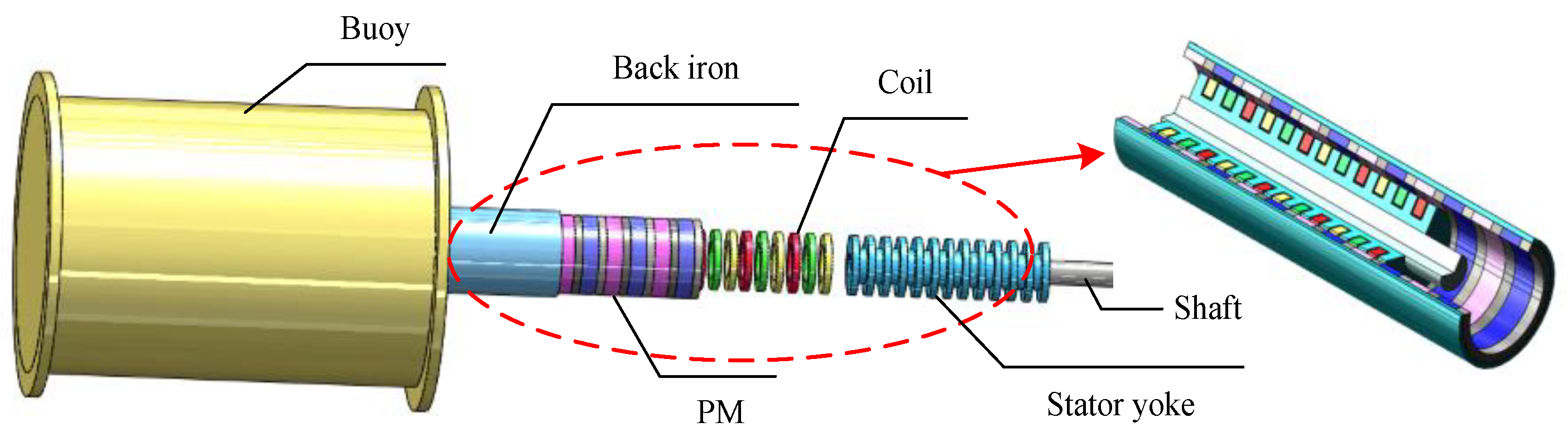
2. Structures and Operation Principle of Generators

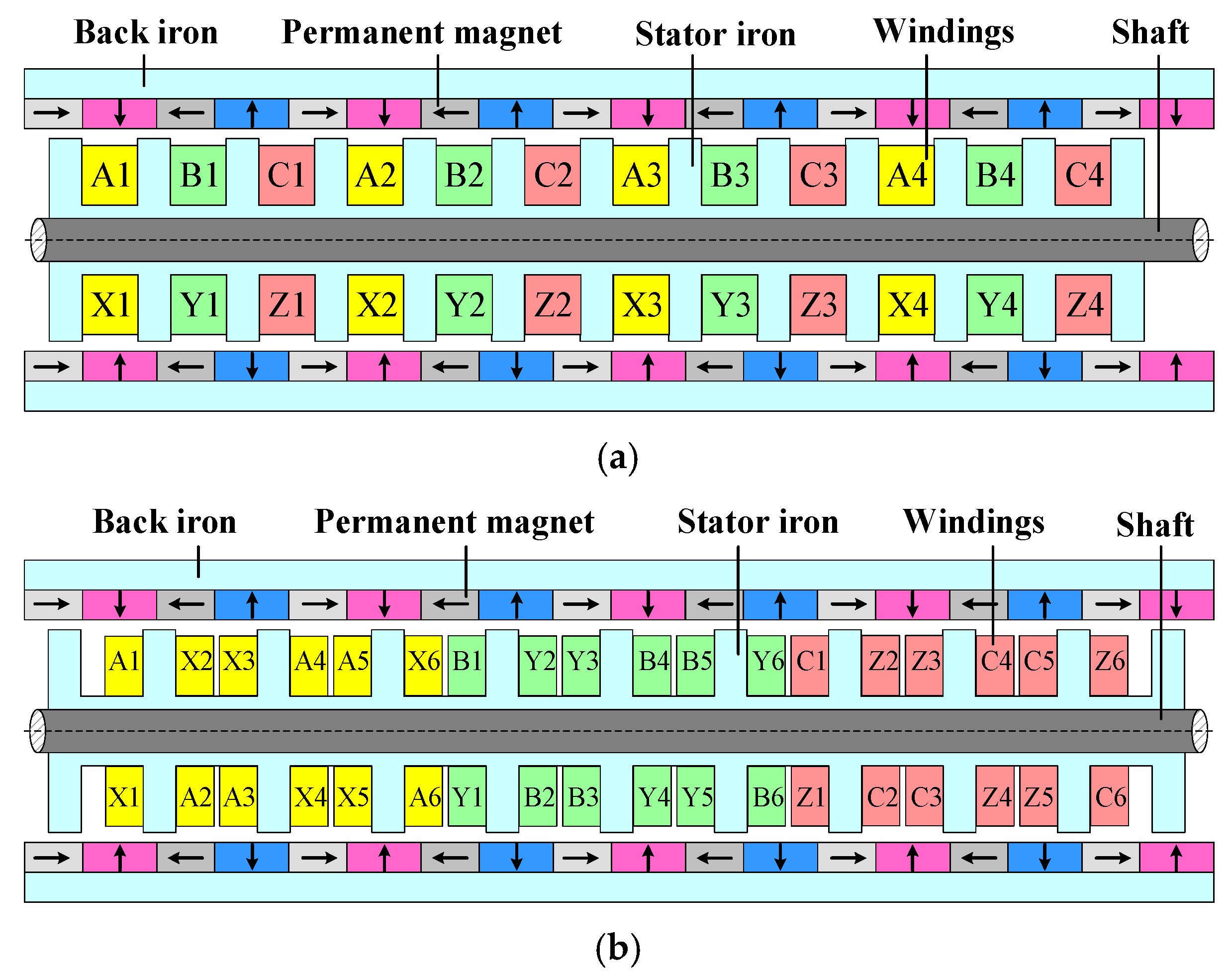
2.1. Structures of GW and CW

The structure of the GW is shown in Figure 1a. The structure includes a secondary(mover), primary(stator) and air gap. The secondary includes permanent magnet and back iron. The permanent magnet adopts a quasi-Halbach structure, which can strengthen the air gap magnetic field and weaken the magnetic field of the back iron; thus, reducing the thickness of the back iron. The primary includes a stator core, stator winding, and shaft. The stator core is provided with 12 annular slots along the axial direction. Each slot is embedded with a set of pancake windings. The generator uses an 8-pole/12-slot combination. The novel Gramme winding connection mode is shown in Figure 1a. Taking phase A as an example, A1, A2, A3, and A4 represent the direction of the winding entering the cross section, and X1, X2, X3, and X4 represent the direction of the winding leaving the cross section. The winding connections of phase A are A1, X1, A2, X2, A3, X3, and A4, X4. The winding connections of phase B and phase C are similar to that of phase A. The proposed GW has the following novel features:
  • All coils are wound in the same direction.
  • The minimum unit module of the GW is two poles and three slots.
  • Only one phase coil is embedded in each stator slot. Each phase coil is arranged in sequence to facilitate expansion into a multiphase generator.
The structure of the CW proposed in [12] is shown in Figure 1b. The difference between the CW and GW lies in the ratio of the pole and slot and winding connection mode. The CW uses 8-pole/9-slot combination. The winding connection mode of the generator is shown in Figure 1b. ‘A’ and ‘X’ have the same meaning as above. The winding connections of phase A are A1, X1, A2, X2...A6, X6. The winding connection of phase B and phase C are similar to that of phase A.

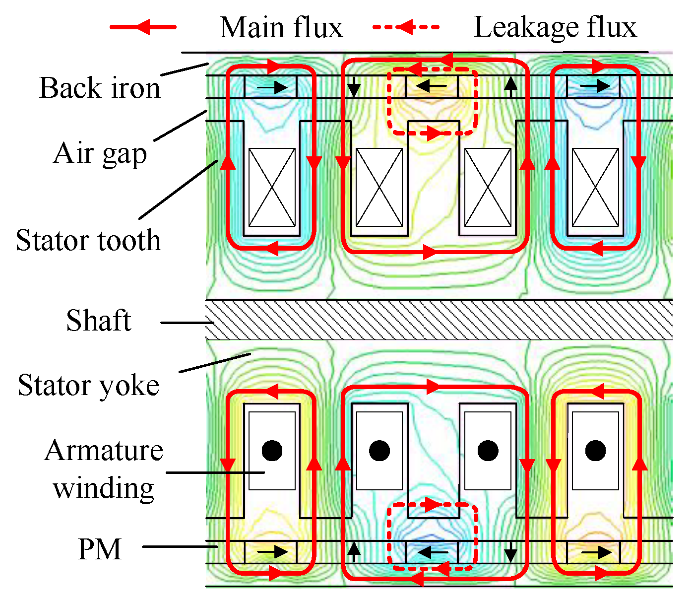
2.2. Operation Principle of GW

As shown in Figure 2, the DD-WEC is mainly composed of a buoy and a permanent-magnet linear generator. The permanent magnet and back iron of the generator is fixed inside the buoy and packaged into a whole. The stator winding and core of the generator are fixed on the shaft and packaged into a whole. There is an air gap between the stator and the permanent magnet. The anchor is connected to the shaft and fixed to the seabed. The buoy is placed on the sea surface and is driven to make linear motion by the ups and downs of the waves. The flux of the permanent magnet cuts the stator three-phase winding to generate the EMF. When the generator is loaded, current is generated in the windings. At this time, the internal magnetic field of the generator is generated by the combined action of the permanent magnet and the load current. The distribution of flux lines when the generator operates under no load conditions is shown in Figure 3.

3. Parameter Design and Analytical Model

Based on the structural parameters of the CW in [12], the structural parameters of the GW were preliminarily designed. To compare the power density of the two generators, the volume of GW should be consistent with that of CW. The polar distance, thickness of the permanent magnet, thickness of the back iron, thickness of the air gap, effective length of the winding, and outer and inner diameters of stator in the GW are the same as in the CW.
As the number of stator slots of GW increases, the width of stator tooth and slots needs to be redesigned to ensure that two generators have the same slot filling factor under the same number of turns. The preliminary design of tooth width and slot width of GW is calculated as follows:
S f   =   N i N s d 2 A ef
A ef   =   A s A i
A s   =   b * h
where S f , N i , N s , d , A ef , A s , A i , b and h are slot filling factor, number of strands, number of turns, diameter of wire, effective slot area, actual slot area, slot insulation area, slot width and slot depth, respectively.
The results show that the width of slot and tooth of GW are 7.5 mm and 6.9 mm respectively. The main parameters of the two generators are listed in Table 1.
The equations of magnetic flux, back EMF, terminal voltage and magnetomotive force of the generator are as follows:
{ Φ =   B · d s =   ( × A ) · d s E = N s d Φ p w d t U = i R + L d i d t E F P M = Φ R m
where A is the vector magnetic potential, Φ p w is the no-load flux of a coil, R is the phase resistance, L is the phase inductance, i is the phase current, R m is the reluctance.
The distribution of magnetic field under Halbach magnetization can be calculated by vector magnetic potential method. The influence of slotting may be accounted by introducing a Carter coefficient [9]. The back EMF of the generator is calculated by the flux linkage passing through the winding. The inductance and resistance of each phase can be calculated by the Equations (5) and (6):
L = ψ w i
R = ρ L S
where ψ w is the flux linkage of phase winding, ρ is the resistivity of copper, L is the length of the conductor of a phase winding, S is the cross-sectional area of the conductor.
The flux linkage is related to the position of the mover and the load current. When the generator is in no-load operation, the load current is 0 and only the flux linkage generated by the permanent magnet. The three-phase flux linkage of GW and CW is shown in Figure 4a. Figure 4a shows that the flux linkage varies periodically with the position of the mover. When the generator is loaded, the change of the load current will affect the effective value of the flux linkage. Assuming that the load current is from 0 A to 18 A, the curve of the effective value of the flux linkage changing with the current is obtained, as shown in Figure 4b. Figure 4b shows that the strength of the armature reaction will affect the effective value of the flux linkage. When the load current is <7 A, the armature reaction is relatively weak, and the flux linkage decreases relatively slowly. When the load current is ≥7 A, the effective value of the flux linkage decreases rapidly due to the saturation of the iron magnetic circuit and the stronger armature reaction.
The phase inductance can be affected by the position of the mover and the saturation of the iron magnetic circuit. The influence of the position of the mover on the inductance is relatively small and could be omitted, and the influence of the saturation of the magnetic circuit on the inductance is shown in Figure 5.
When the armature current is <7 A, the phase inductance keeps almost stable. When the current is ≥7 A, the inductance is decreased. Hence, when the load current is <7 A, it is the unsaturated region of the magnetic circuit of the generator and provides the basis for selecting the rated current of the generator.

4. Analysis of Electromagnetic Characteristics

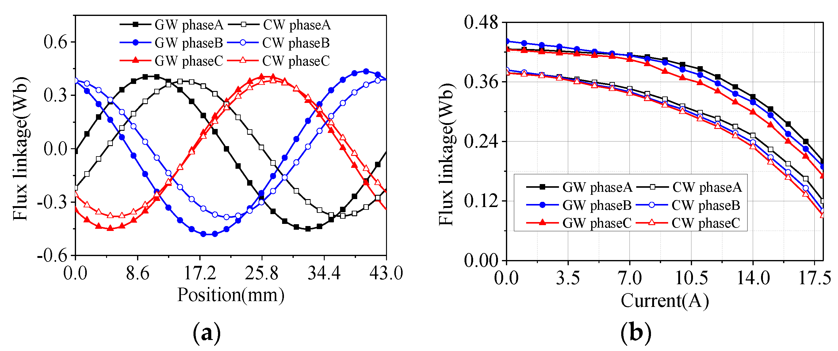
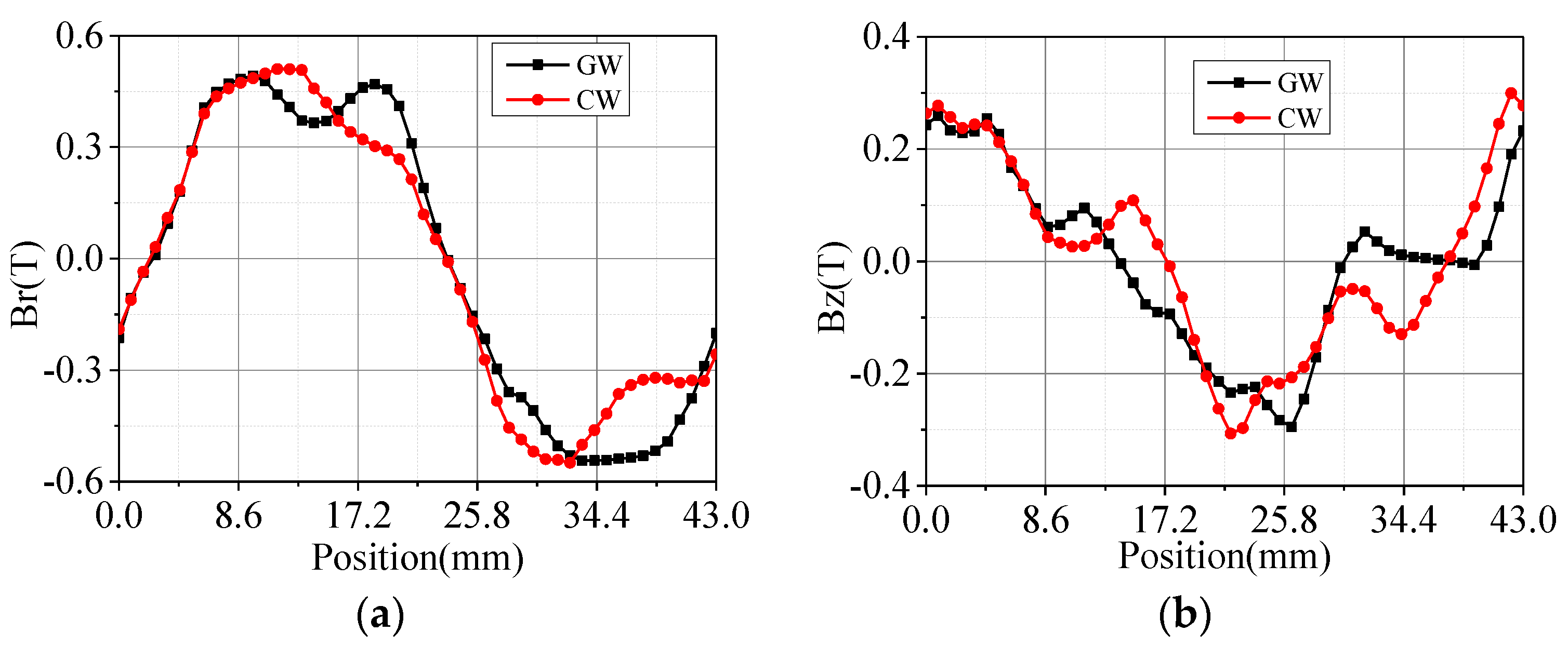
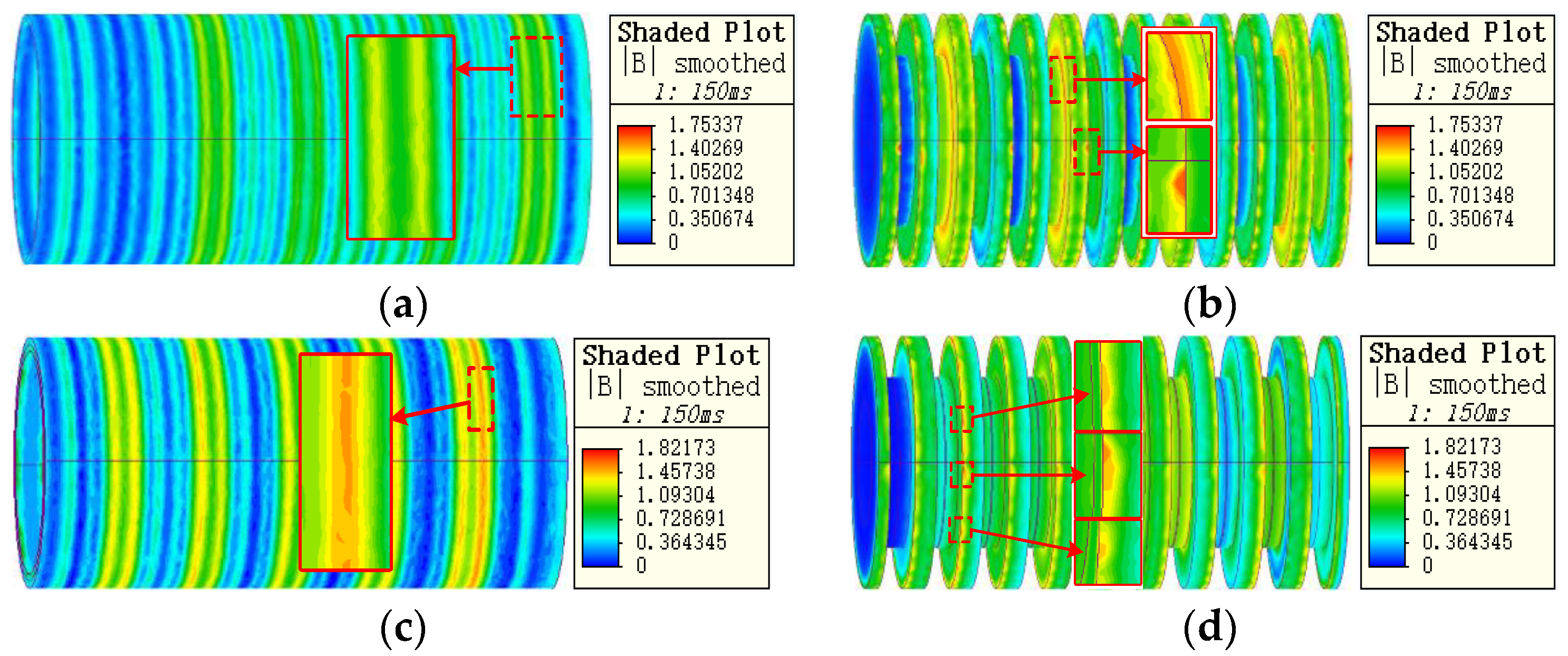
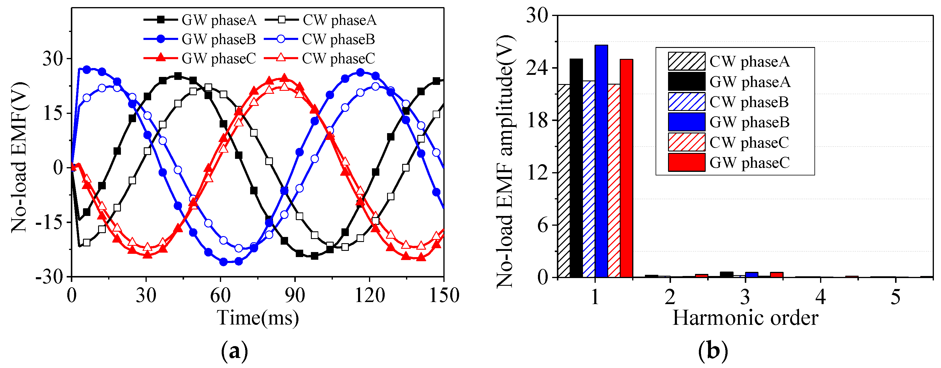
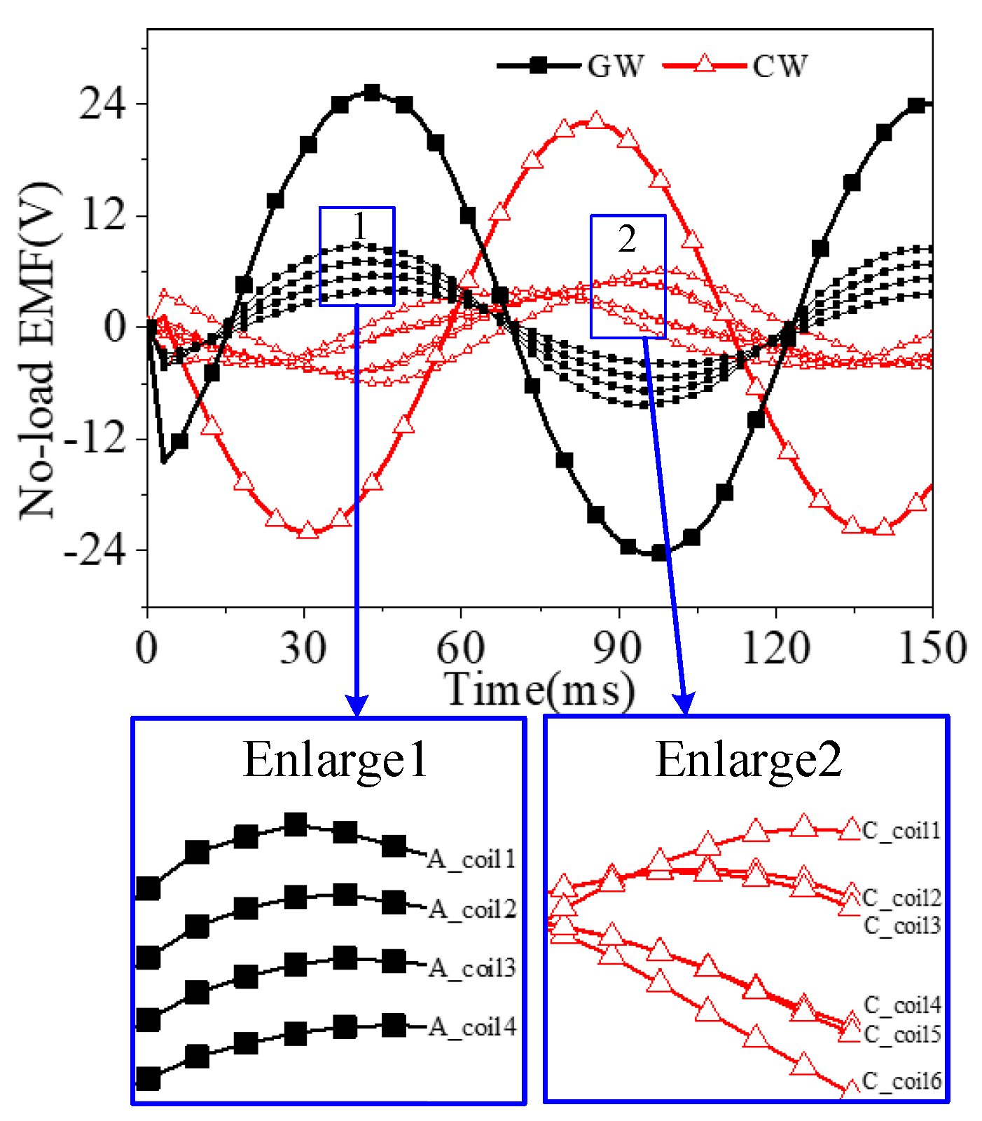
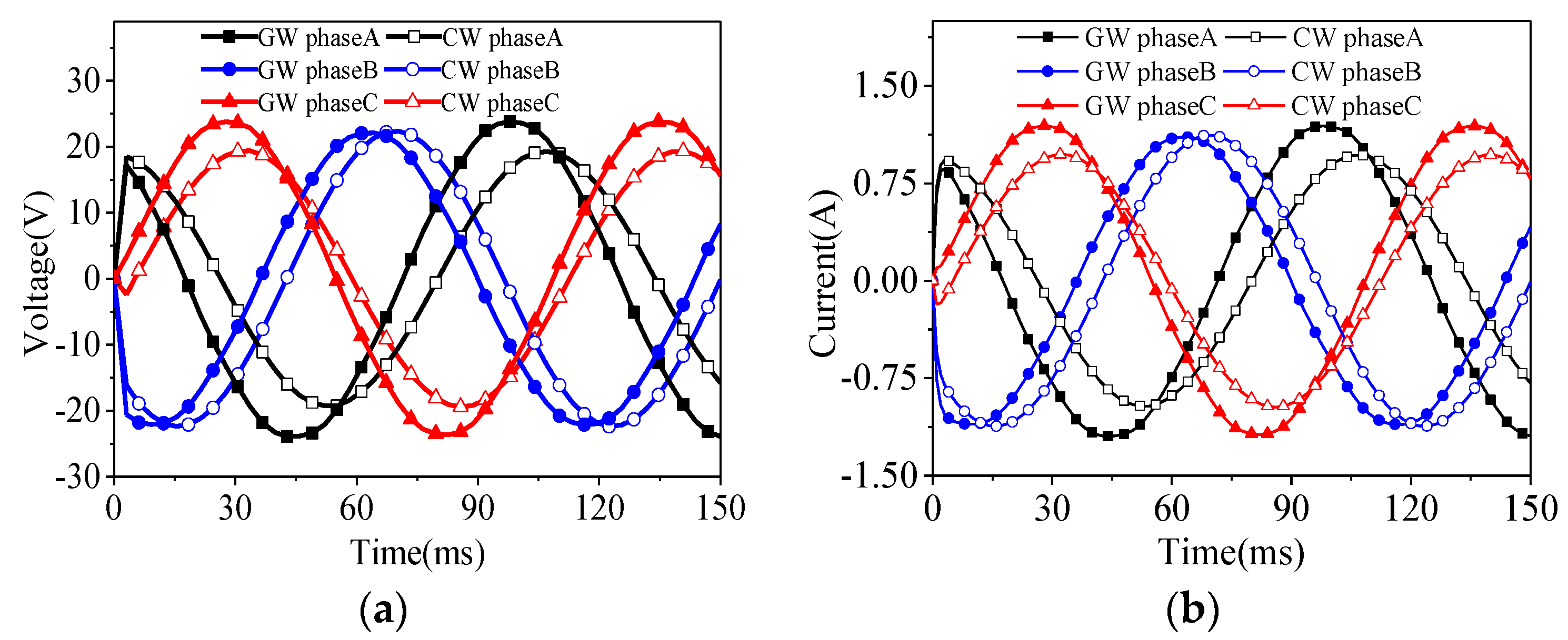
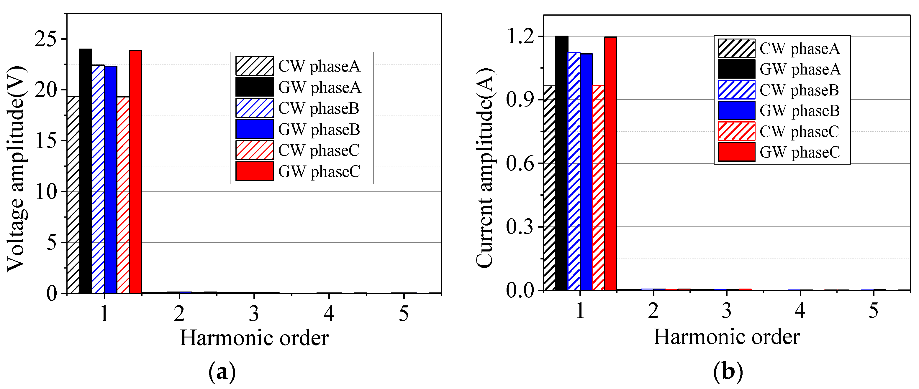
4.1. Analysis of No-Load Characteristics

The electromagnetic characteristics of both generators are compared by the 3D finite element method. The air gap flux density of both generators is shown in Figure 6.
Performing a fast Fourier transform (FFT) on the data in Figure 6 shows that the fundamental amplitude of the radial air gap flux density of GW is 0.55 T, and that of the axial air gap flux density is 0.20 T; the fundamental amplitude of the radial air gap flux density of the CW is 0.51 T, and that of axial air gap flux density is 0.21 T. For TPMLG, the radial air gap flux density is the main factor affecting the magnitude of EMF in the armature windings. The fundamental amplitude of the radial air gap flux density of the GW is 7.8% higher than that of the CW. The comparison of air gap flux density of the two generators is shown in Table 2.
The flux density distributions of the stator core and back iron of the two generators are shown in Figure 7, where the flux density of the stator tooth and stator yoke of the GW are the largest, approximately about 1.75 T. The maximum flux density of the CW appears in the stator tooth, which is approximately 1.8 T.
In the wave energy power generation system, the moving part of the generator follows the wave to do complex and irregular movement. In order to simplify the analysis in this paper, in the ideal case, the equation of wave velocity can be expressed as:
v = H π λ sin 2 π λ t
where H and λ are wave height and wavelength respectively. In this paper, the simulated wave height is 0.4 m, wavelength is 2 m, and the period is 2 s. In order to deal with the data conveniently and without losing the verification of the motor performance, and the calculated average speed is 0.4 m/s, making the generator move at a constant speed under this value. Figure 8 shows the waveforms of the no-load EMF of two generators.
Figure 8a shows that the waveform of the no-load EMF of the two generators is close to a sine wave. Due to the disconnection of both ends of the linear generator, there is an edge-end effect [20], so the A and C phase voltages of the two generators are slightly offset. The amplitude of the three-phase EMF of the GW is higher than that of the CW, and the frequency of the linear generator can be calculated as follows:
f   =   v / 2 τ
where τ is the pole pitch of linear generator. The polar pitch is 21.5 mm, which is shown in Table 1. So, the frequency of the three-phase EMF is 9.3 Hz. The harmonic component of the EMF is obtained by Fourier analysis, as shown in Figure 8b.
As Figure 8b shows, the finite length of the tubular linear generator armature causes the magnetic field to be distorted where the two ends are disconnected, forming a longitudinal end effect. And due to the asymmetry of the three-phase winding in space, the mutual inductance of the three-phase winding is asymmetric, resulting in an imbalance three-phase voltage and current. Voltage imbalance ( ε u ) can be calculated as follows:
ε u ( % )   =   U max U min U max   ×   100 %
where U max and U min are maximum voltage and minimum voltage, respectively.
The voltage asymmetry can be reduced by the auxiliary slots in CW, but it cannot be completely eliminated. The voltage imbalance of CW and GW are calculated to be 2% and 6%, respectively. The existence of voltage asymmetry leads to uneven air gap magnetic field, which in turn has some consequences, such as higher THD, higher loss, lower efficiency, higher temperature rise, and so forth. Moreover, the large voltage asymmetry makes the generator unable to be directly connected to the power system. Therefore, it is necessary to use power electronic conversion device to convert irregular three-phase power into usable power [21], so we make rectified analysis in the next chapter.
The comparison of the fundamental harmonic of the EMF of two generators are shown in Table 3. Total harmonic distortion (THD) is introduced to analyse the sine of no-load EMF, as shown in Table 4. THD is expressed by the ratio between the sum of harmonics and the fundamental harmonic. The results show that the THD of GW is three times higher than that of CW. The higher harmonics of two generators mainly include the second and third harmonics.
According to the above analysis, the fundamental and harmonic components of the EMF of the GW are higher than those of the CW. To analyse the reasons, take phase A as an example to compare the EMF of each group of coils in phase A of two generators, as shown in Figure 9.
Because the stator windings are distributed differently, the winding factors of the two generators have changed. The phases of the EMF of the four coils of each phase winding of the GW are basically the same, which can make the EMF of each coil reach the maximum value at the same time. Therefore, the combined total EMF of each phase reaches the maximum value. Among the six coils in each phase winding of the CW, the EMF phase of the coils in the same slot are the same (as shown in Figure 9, coil2 and coil3, coil4 and coil5). However, the EMF of the coils in different slots have a phase difference. Therefore, the amplitude of the total EMF per phase is affected, but the sinusoidal waveform is improved.

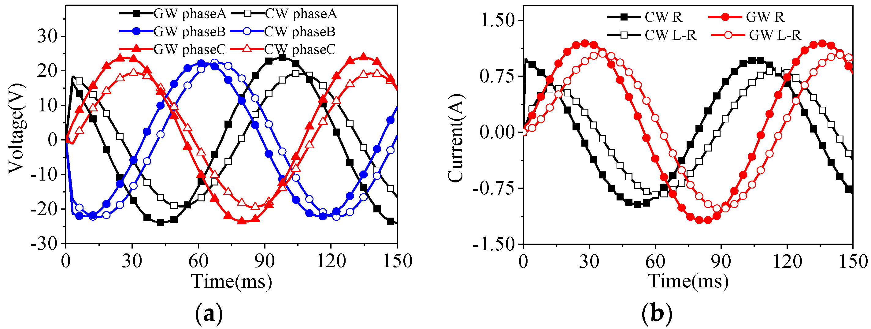
4.2. Analysis of Load Characteristics

Through finite element analysis, the voltage and current waveforms of the two generators were obtained when the load was 20 Ω and the speed was 0.4 m/s, as shown in Figure 10.
Figure 10 shows that, different from the no-load condition, when the generator is loaded, the armature winding will have current flowing through, causing armature reaction and thus affecting the output voltage of the generator. The maximum value in the current waveform is about 1.2 A, which is always in the unsaturated region in Figure 5. The star three-phase symmetrical load will cancel out the third harmonics in the voltage. Through Fourier analysis, as Figure 11 shows, the content of high-order harmonics other than fundamental waves is extremely low. The fundamental amplitude of the phase A and phase C voltages of the GW are 24% higher than that of the corresponding phase voltage of the CW and the fundamental amplitude of the phase B is basically the same. The voltage imbalance of CW and GW after load are calculated to be 15% and 7%, respectively. The results show that the armature reaction of the novel winding will not cause greater voltage imbalance under load and the output voltage of GW is higher than that of CW.
In practical applications, most loads are resistor-inductance. To more comprehensively compare the performance of the two generators. Resistor-inductance load (R = 20 Ω, L = 0.2 H) is added to each phase of generator.
Through finite element analysis, Figure 12a shows the voltage under resistor-inductance load. And the current under pure resistive load and resistor-inductance load is shown in Figure 12b. Comparing Figure 10a to Figure 12a, the load voltage of the two generators remains basically unchanged. It shows that the generator has strong load capacity at low speed. As Figure 12b shows, the maximum current of resistor-inductance load is slightly less than that of pure resistive load, and the phase between them is also offset. The offset Angle is determined by the value of the inductive load.
Adding a series of loads makes it possible to obtain the output voltage and output power of the generator under different load currents, as shown in Figure 13.
In Figure 13, the external characteristic curves of the two generators show a downward trend, and the slopes are the same. With the increase of load current, the output voltage of phase A and phase C of the GW was 30% higher than that of the CW. The output power of the GW was 30% higher than that of the CW. The power density (ρ) of generator is calculated as follows:
ρ   =   P / V
where P and V are output power of generator and effective volume of armature core respectively. The effective volumes of armature core of GW and CW are 5.8 × 10⁻⁴ m3 and 6.1 × 10⁻⁴ m3 respectively. The output power of the generator is shown in Table 5 and Table 6. The power density of GW and CW are calculated as 70.93 kW/m3 and 51.24 kW/m3 respectively when the load is 20 Ω.

4.3. Loss and Efficiency

The copper loss, iron loss and additional loss of the generator are analysed in this paper. The additional loss caused by voltage imbalance is calculated by the method of symmetrical components. It includes the copper loss caused by negative sequence current and the iron loss and stray loss caused by negative sequence magnetic field in air gap. Due to the small proportion of additional loss, it can be ignored in order to simplify the analysis. Moreover, due to the secondary of the generator in this system is always in a low-speed state, its working frequency is 9.3 Hz, which is much lower than the power frequency. The eddy current loss is proportional to the square of the frequency, so the eddy current loss of the core is also neglected. Therefore, only hysteresis loss of core and copper loss of winding are considered in this paper.
According to the above analysis, copper loss, hysteresis loss and efficiency under different load conditions are respectively calculated, as shown in Table 5 and Table 6.
As can be seen from Table 5 and Table 6, when the load resistor increases, as the load resistance increases, the output power decreases. As the load current decreases, the copper loss, hysteresis loss and heat loss decrease and the efficiency increases. When the load was 20 Ω, the efficiencies of the two generators were close to 90%, and the output power of the GW was 30% higher than that of the CW.

4.4. Voltage Regulation

The voltage regulation of the generator can be calculated from the external characteristics. The voltage regulation ( Δ U ) is calculated as follows:
Δ U   ( % ) = E 0 U U N   ×   100 %
where E 0 , U and U N are the no-load EMF, and the output voltage and the rated voltage, respectively.
Table 7 and Table 8 show the voltage regulation for the GW and CW under a series of resistive loads. When the rated load was 20 Ω, the three-phase voltage regulation of the CW was 14.06%, 0.27%, and 14.60%. The three-phase voltage regulation of the GW was 4.16%, 19.14%, and 4.48%. Because of the imbalance of the three-phase voltage, the three-phase voltage regulation was also different. The voltage regulation of phase A and phase C of the CW was larger, while that of the GW was only phase B.

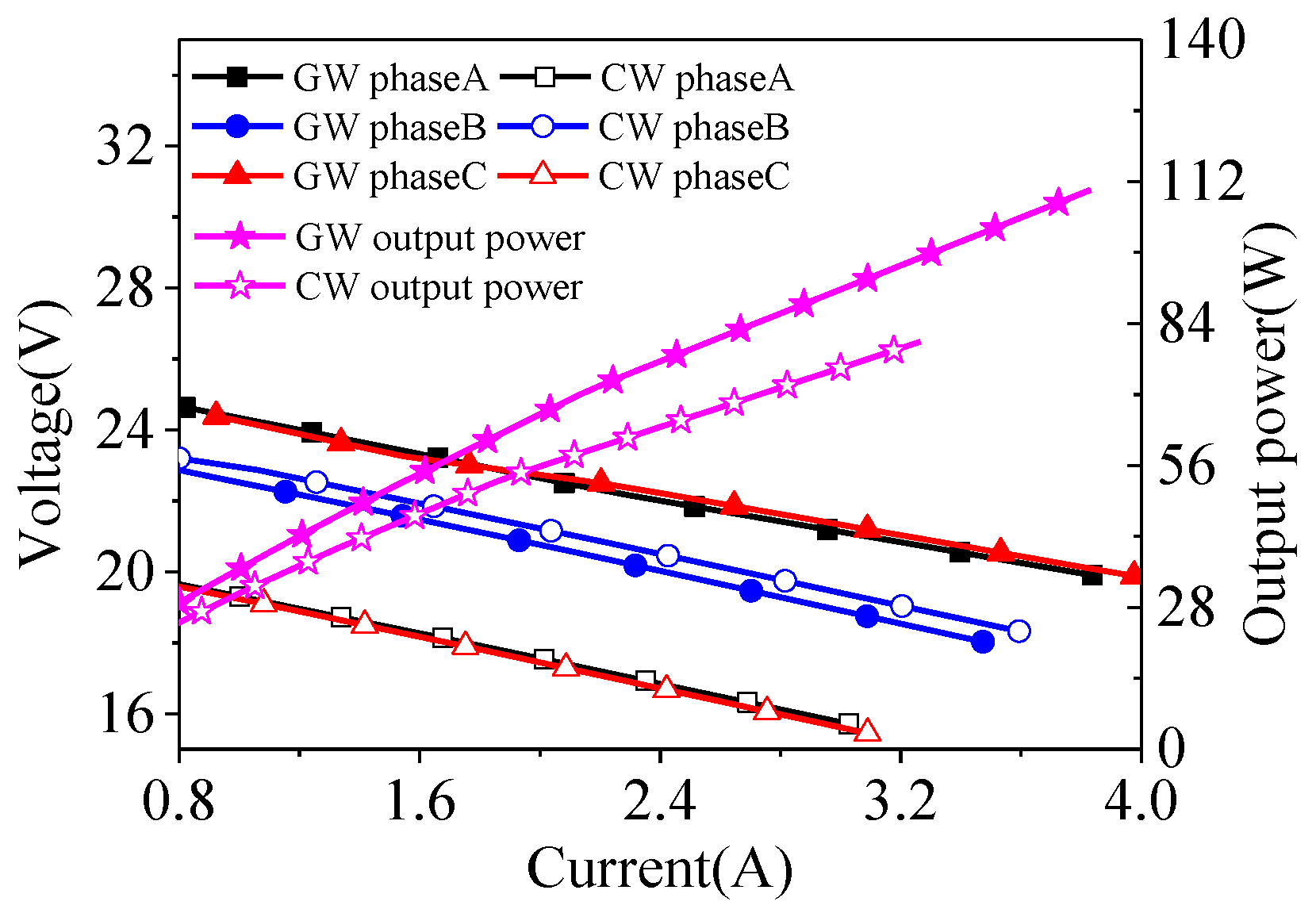
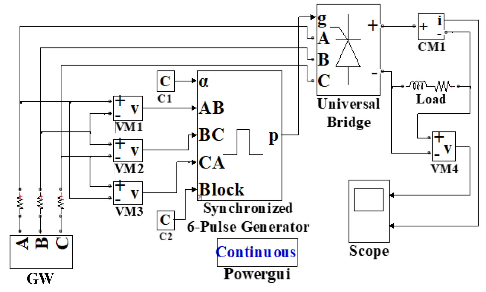
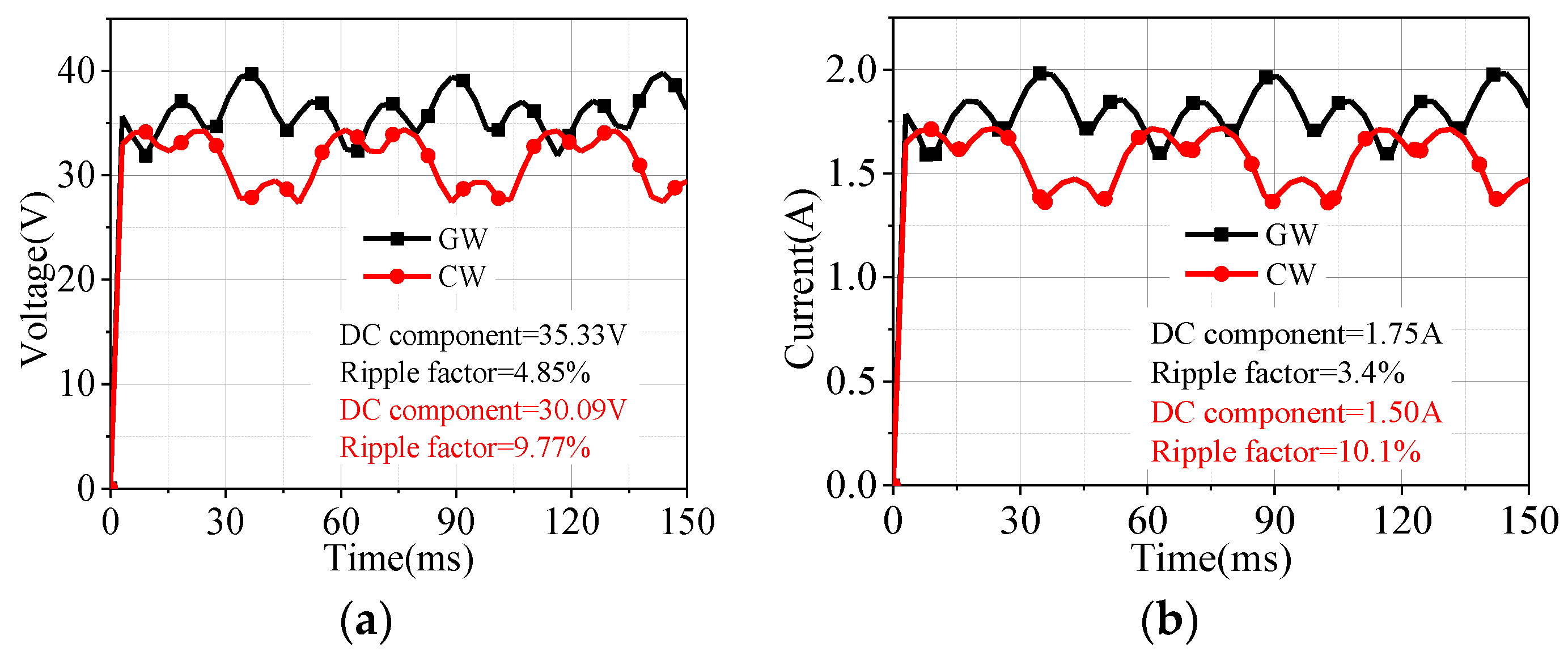
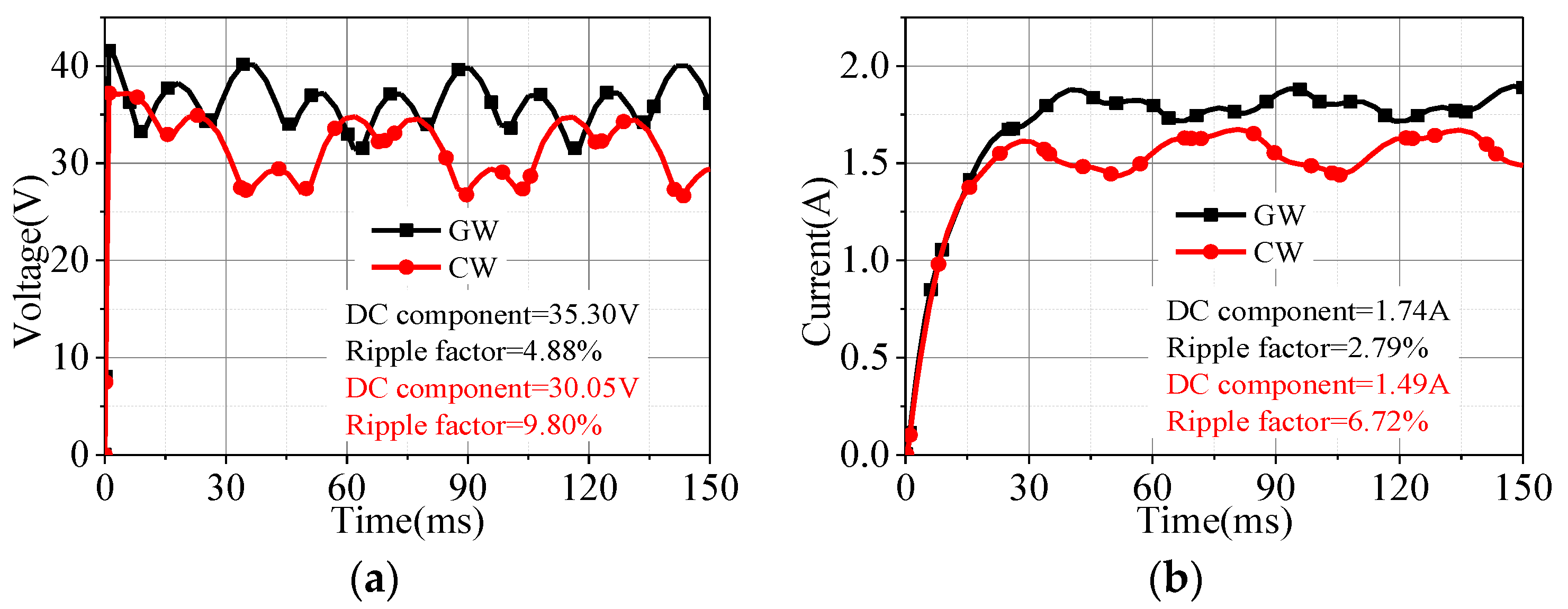
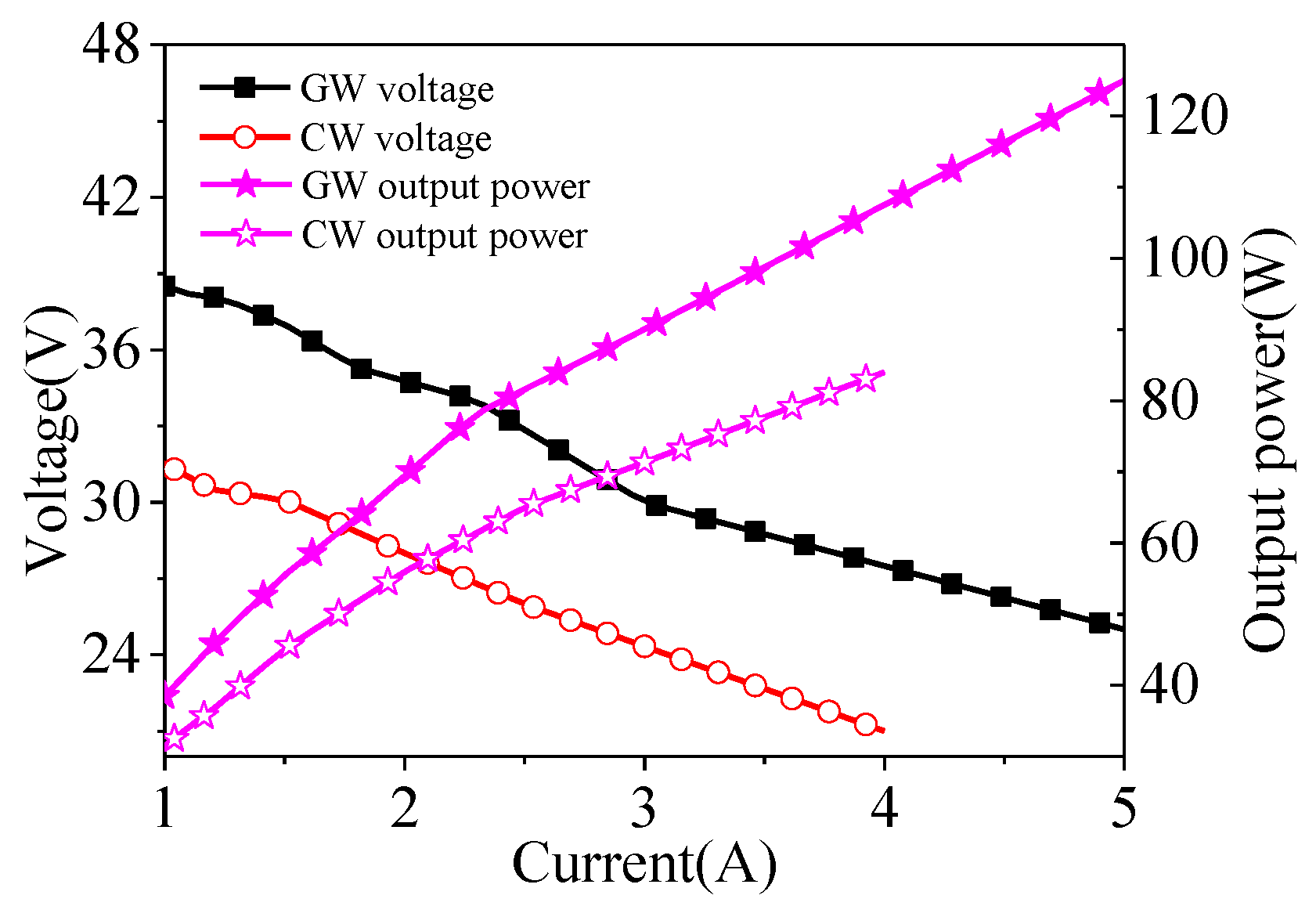
5. DC Load Characteristics

Considering the later operation environment of the generator, it is usually necessary to rectify and transform the AC energy, so this chapter studies the DC load characteristics of the two generators, which lays the foundation for the follow-up study. When the speed of both generators was 0.4 m/s, the output terminals of the generator were connected to the three-phase full-control bridge rectifying circuit, and then directly connected to the load without passing through the filter circuit. Figure 14 shows simulation diagram of rectifying circuit.
When the load was R = 20 Ω and firing angle was α = 0° (natural commutation), the voltage and current were as shown in Figure 15.
As Figure 15 shows, the voltage and current fluctuate periodically because of the conduction and cut off of thyristor devices. Fourier analysis shows that the DC component of the voltage of GW and CW are 35.3 V and 30.1 V, respectively. And the DC component of the current of GW and CW are 1.8 A and 1.5 A, respectively. Compared with the CW, the output voltage of the GW increased by 17%, and the output current increased by 20%. The smoothness of voltage and current on rectified load can be characterized by ripple factor. The ripple factor (s) is expressed as:
s   =   A 1 A 2   ×   100 %
where A 1 and A 2 are the fundamental harmonic and the DC component, respectively. The results show that the voltage and current of ripple factor of GW decrease by more than 50% than that of CW.
To reduce load current ripple, a proper inductance is usually connected in series in rectifying circuit. To compare the output capacity of the two generators, the impedance must be the same. Because the two generators have the same frequency, the same resistor and inductance value can ensure the same impedance. We set the DC load R = 20 Ω, L = 0.2 H, and α = 0°. The output voltage and current are shown in Figure 16.
Comparing Figure 15b to Figure 16b, with the addition of inductive load, the output current waveform becomes more stable, the ripple factor decreases, and the DC component remains basically unchanged. The output voltage and power of the two generators under different load currents are shown in Figure 17.
According to Figure 17, compared with the CW, the output voltage and power of the GW are increased by approximately 30%.

6. Conclusions

In this work, a novel Gramme winding tubular permanent-magnet linear generator with higher winding factor is proposed and compared with a concentrated winding tubular permanent-magnet linear generator. The air gap flux density, external characteristics, voltage regulation, and output power of the generators are analysed by using 3D finite-element method. Compared with concentrated winding, the results show that the output voltage of Gramme winding tubular permanent-magnet linear generator is increased and the voltage imbalance is reduced. Under the same load, the power density of Gramme winding tubular permanent-magnet linear generator is increased by 38%. Therefore, the Gramme winding tubular permanent-magnet linear generator has a certain application prospect in wave energy conversion or similar fields.

Author Contributions

Conceptualization, H.F., J.W. and J.S.; data curation, H.F. and Z.C.; formal analysis, C.G. and X.X.; methodology, J.W. and J.S.; software, J.W.; writing—original draft, J.W.; resources, H.F., J.S. and X.X. All authors have read and agreed to the published version of the manuscript.

Funding

This work was supported in part by Foundation for University Key Teachers from Henan Province of China (NO.2017GGJS051).

Conflicts of Interest

The authors declare no conflict of interest.

References

  1. Xiao, X.; Bai, N.Z.; Kang, Q.; Nie, Z.X.; Huang, X.R. A Review of the Development of Wave Power System and the Research on Direct-Drive Wave Power System. Trans. China Electrotech. Soc. 2014, 29, 1–11. [Google Scholar]
  2. Faiz, J.; Nematsaberi, A. Linear Electrical Generator Topologies for Direct-Drive Marine Wave Energy Conversion—An Overview. IET Renew. Power Gener. 2017, 11, 1163–1176. [Google Scholar]
  3. DelliColli, V.; Cancelliere, P.; Marignetti, F. A Tubular-Generator Drive for Wave Energy Conversion. IEEE Trans. Ind. Electron. 2006, 53, 1152–1159. [Google Scholar]
  4. Wahyudie, A.; Jama, M.; Susilo, T.B. Design and Testing of a Laboratory Scale Test Rig for Wave Energy Converters Using a Double-Sided Permanent Magnet Linear Generator. IET Renew. Power Gener. 2017, 11, 922–930. [Google Scholar] [CrossRef]
  5. Polinder, H.; Damen, M.; Gardner, F. Linear PM Generator System for Wave Energy Conversion in the AWS. IEEE Trans. Energy Convers. 2004, 19, 583–589. [Google Scholar] [CrossRef] [Green Version]
  6. Polinder, H.; Mecrow, B.C.; Jack, A.G. Conventional and TFPM Linear Generators for Direct-Drive Wave Energy Conversion. IEEE Trans. Energy Convers. 2005, 20, 260–267. [Google Scholar] [CrossRef]
  7. Dobzhanskyi, O. Comparison Analysis of Cylindrical and Rectangular Linear Permanent Magnet Transverse-Flux Machines for Wave Energy Applications. In Proceedings of the 2019 12th International Symposium on Linear Drives for Industry Applications (LDIA), Neuchatel, Switzerland, 1–3 July 2019; pp. 1–5. [Google Scholar]
  8. Musolino, A.; Raugi, M.; Rizzo, R.; Sani, L. A Semi-Analytical Model for the Analysis of a Permanent Magnet Tubular Linear Generator. IEEE Trans. Ind. Appl. 2018, 54, 204–212. [Google Scholar] [CrossRef]
  9. Wang, J.B.; Howe, D.; Jewell, G.W. Fringing in Tubular Permanent-Magnet Machines: Part I. Magnetic Field Distribution, Flux Linkage, and Thrust Force. IEEE Trans. Magn. 2003, 39, 3507–3516. [Google Scholar] [CrossRef]
  10. Wang, J.B.; Howe, D.; Jewell, G.W. Fringing in Tubular Permanent-Magnet Machines: Part II. Cogging Force and its Minimization. IEEE Trans. Magn. 2003, 39, 3517–3522. [Google Scholar] [CrossRef] [Green Version]
  11. Wang, J.B.; West, M.; Howe, D. Design and Experimental Verification of a Linear Permanent Magnet Generator for a Free-Piston Energy Converter. IEEE Trans. Energy Convers. 2007, 22, 299–306. [Google Scholar] [CrossRef]
  12. Liu, C.Y.; Yu, H.T.; Hu, M.Q. Research on a Permanent Magnet Tubular Linear Generator for Direct Drive Wave Energy Conversion. IET Renew. Power Gener. 2014, 8, 281–288. [Google Scholar] [CrossRef]
  13. Liu, C.Y.; Yu, H.T.; Liu, Q. Research on a Double Float System for Direct Drive Wave Power Conversion. IET Renew. Power Gener. 2017, 11, 1026–1032. [Google Scholar] [CrossRef]
  14. Huang, L.; Hu, M.Q.; Chen, Z. Research on a Direct-Drive Wave Energy Converter Using an Outer-PM Linear Tubular Generator. IEEE Trans. Magn. 2017, 53, 1–4. [Google Scholar] [CrossRef]
  15. Guo, R.; Yu, H.T.; Xia, T. A Simplified Subdomain Analytical Model for the Design and Analysis of a Tubular Linear Permanent Magnet Oscillation Generator. IEEE Access. 2018, 6, 42355–42367. [Google Scholar] [CrossRef]
  16. Qiu, H.; Zhao, X.; Wei, Y. Influence of Inter-Turn Short-Circuit Fault on the Loss of High Speed Permanent Magnet Generator with Gramme Ring Windings. IET Power Electron. 2019, 12, 1256–1262. [Google Scholar] [CrossRef]
  17. Dong, J.N.; Huang, Y.K.; Jin, L. Electromagnetic and Thermal Analysis of Open-Circuit Air Cooled High-Speed Permanent Magnet Machines with Gramme Ring Windings. IEEE Trans. Magn. 2014, 50, 1–4. [Google Scholar] [CrossRef]
  18. Nukki, R.; Kilk, A.; Kallaste, A. Generator Mode Analysis of Exterior-Rotor PM Synchronous Machine with Gramme’s Winding. In Proceedings of the IEEE 5th International Conference on Power Engineering, Energy and Electrical Drives (POWERENG), Riga, Latvia, 11–13 May 2015; pp. 347–352. [Google Scholar]
  19. Pirisi, A.; Gruosso, G.; Zich, R.E. Novel Modeling Design of Three Phase Tubular Permanent Magnet Linear Generator for Marine Applications. In Proceedings of the International Conference on Power Engineering, Energy and Electrical Drives, Lisbon, Portugal, 18–20 March 2009; pp. 78–83. [Google Scholar]
  20. Lu, J.Y.; Ma, W.M. Investigation of Phase Unbalance Characteristics in the Linear Induction Coil Launcher. IEEE Trans. Plasma Sci. 2011, 39, 110–115. [Google Scholar] [CrossRef]
  21. Trapanese, M.; Boscaino, V.; Cipriani, G. A Permanent Magnet Linear Generator for the Enhancement of the Reliability of a Wave Energy Conversion System. IEEE Trans. Ind. Electron. 2019, 66, 4934–4944. [Google Scholar] [CrossRef]
Figure 1. Structure of two generators: (a) GW; (b) CW.
Energies 13 05943 g001
Figure 2. Generator structure and assembly.
Energies 13 05943 g002
Figure 3. No-load flux of GW.
Energies 13 05943 g003
Figure 4. Flux linkage of GW and CW: (a) no-load; (b) load.
Energies 13 05943 g004
Figure 5. Inductance versus the load current.
Energies 13 05943 g005
Figure 6. Air gap flux density: (a) radial flux density; (b) axial flux density.
Energies 13 05943 g006
Figure 7. Comparison of flux density of iron core: (a) back iron of GW; (b) stator core of GW; (c) back iron of CW; (d) stator core of CW.
Energies 13 05943 g007
Figure 8. Comparison of no-load EMF: (a) waveform; (b) FFT.
Energies 13 05943 g008
Figure 9. Comparison of single-phase no-load EMF waveforms.
Energies 13 05943 g009
Figure 10. Comparison of resistive load: (a) voltage; (b) current.
Energies 13 05943 g010
Figure 11. Comparison of resistive load FFT: (a) voltage; (b) current.
Energies 13 05943 g011
Figure 12. Comparison of resistor-inductance load: (a) voltage; (b) current.
Energies 13 05943 g012
Figure 13. Output voltage and power changing with load currents.
Energies 13 05943 g013
Figure 14. Simulation diagram of rectifying circuit.
Energies 13 05943 g014
Figure 15. Comparison of resistive load: (a) output voltage; (b) output current.
Energies 13 05943 g015
Figure 16. Comparison of resistor-inductance load: (a) output voltage; (b) output current.
Energies 13 05943 g016
Figure 17. Output voltage and power changing with load currents.
Energies 13 05943 g017
Table 1. Key parameters of CW and GW.
ParametersCWGW
Pole pitch21.5 mm21.5 mm
Magnet length for r direction14.5 mm14.5 mm
Magnet length for z direction7 mm7 mm
Thickness of PM3 mm3 mm
Thickness of back iron3 mm3 mm
Outer radius of stator92 mm92 mm
Tooth width9 mm6.9 mm
Slot width10.5 mm7.5 mm
Slot depth15 mm15 mm
Air gap3 mm3 mm
Number of turns6090
Number of coils64
Type of the PMNdFeB35NdFeB35
Type of the coreM600M600
Table 2. Comparison of air gap flux density.
GWCW
Radial0.55 T0.51 T
Axial0.20 T0.21 T
Table 3. Comparison of fundamental harmonic of three-phase no-load EMF.
PhaseCWGWIncreases
A22.09 V25 V13.17%
B22.49 V26.6 V18.27%
C22.12 V24.97 V12.88%
Table 4. Comparison of three-phase no-load EMF THD.
PhaseCWGW
A2.96%9.49%
B2.91%6.46%
C3.48%12.13%
Table 5. Loss and efficiency of GW.
LoadCopper LossHysteresis LossOutput PowerEfficiency
5 Ω37.29 W10.4 W110.35 W69.82%
10 Ω12.04 W4.02 W71.29 W81.61%
15 Ω5.86 W2.32 W52.02 W86.41%
20 Ω3.47 W1.38 W41.14 W89.44%
25 Ω2.29 W1.22 W33.99 W90.62%
30 Ω1.63 W0.97 W28.95 W91.76%
Table 6. Loss and efficiency of CW.
LoadCopper LossHysteresis LossOutput PowerEfficiency
5 Ω27.17 W10.26 W80.39 W68.23%
10 Ω9.04 W3.91 W53.52 W80.51%
15 Ω4.45 W2.16 W39.54 W85.67%
20 Ω2.64 W1.12 W31.26 W89.26%
25 Ω1.74 W1.05 W25.83 W90.23%
30 Ω1.23 W0.92 W21.99 W91.06%
Table 7. Voltage regulation rate of GW.
LoadABCΔUAΔUBΔUC
5 Ω19.74 V17.85 V19.88 V21.9%39.1%21.3%
10 Ω22.26 V20.65 V22.45 V11.4%26.6%10.5%
15 Ω23.39 V21.74 V23.25 V6.7%21.7%7.1%
20 Ω24.00 V22.32 V23.89 V4.1%19.1%4.4%
25 Ω24.38 V22.68 V24.30 V2.5%17.5%2.7%
30 Ω24.63 V22.93 V24.57 V1.5%16.4%1.6%
Table 8. Voltage regulation rate of CW.
LoadABCΔUAΔUBΔUC
5 Ω15.56 V17.97 V15.45 V33.7%20.1%34.5%
10 Ω17.93 V20.74 V17.84 V21.4%7.7%22.1%
15 Ω18.86 V21.84 V18.79 V16.6%2.8%17.2%
20 Ω19.36 V22.42 V19.3 V14.0%0.2%14.6%
25 Ω19.67 V22.79 V19.61 V12.4%−1.3%12.9%
30 Ω19.89 V23.04 V19.83 V11.3%−2.4%11.8%
Publisher’s Note: MDPI stays neutral with regard to jurisdictional claims in published maps and institutional affiliations.

