Abstract
Loss of excitation (LOE) relay is one of the most essential protection elements for synchronous generators in power plants. During the last few decades, several LOE detection methods have been proposed, while limited schemes such as admittance- and impedance-based ones have been adopted for industrial applications. This study investigates and compares the behavior of some practical LOE detection schemes through extensive simulation scenarios, and from the reliability, speed, and security points of view. The simulation scenarios are accomplished by using the real-time-digital-simulator, where the phase domain model of the synchronous generator is used to develop a realistic and typical power generation system. Employing such a system, different types of complete and partial LOE incidents can be applied according to IEEE Standard C37.102-2006, while the performance of any scheme can be assessed through accurate and realistic LOE scenarios.
1. Introduction
The excitation system of a synchronous generator performs a vital rule for its dependable operation. Such a system provides the field DC current for the excitation winding to create the rotor magnetic flux and the generator internal voltage [1].
Based on IEEE Standard C37.102-2006, the supply of excitation for a generator rotor winding might be partially or completely interrupted due to some incidents, such as the following [1]:
- Failure in the voltage regulation system;
- Interruption of the main source of the excitation system;
- Open circuit fault in the excitation circuit;
- Short circuit fault in the excitation circuit ;
- Accidental opening of the excitation circuit breaker;
Additionally, the standard clarifies that partial loss of excitation (LOE) might occur when the voltage regulation system is manually or automatically set on the manual mode [1].
After a LOE occurrence, the excitation current decays steadily at the rate defined by the time constant of the excitation circuit. Moreover, the magnetic coupling of the rotor and the stator deteriorates, the generator accelerates and finally, losses its synchronism. Then, it continues working as an asynchronous generator, drawing its excitation current from the power system in the form of reactive power [2,3]. Long time operation of the generator during such a condition might bring numerous adverse impacts on both the system and the generator, as follows:
- Voltage drop in the adjacent power grid with the likelihood of voltage instability.
- Mechanical damages due to power oscillation;
- Overheating in the end area of the stator core;
- Exceeding stator currents causing thermal impacts;
- Eddy currents in the rotor surface, causing overheating in the rotor body;
Accordingly, LOE detection methods are required to diagnose this phenomenon with high reliability and speed with being secure during the power grid disturbances, for instance, a stable power swing (SPS) event [4].
Numerous LOE protection schemes have been presented in the literature during the last few decades [5,6,7,8,9,10,11,12,13], while some of the recently published ones are as follows:
- Excitation parameter-based schemes [5,6]; such schemes employ the generator excitation signals, namely excitation voltage () and current (), to detect LOE phenomenon. For instance, the method presented in [6] uses and to obtain DC power () injected into the generator excitation circuit. Any LOE failure that interrupts such power injection can easily be detected by the monitoring of .
- Setting-free schemes [7,8]; this category of schemes utilizes the time derivations of some generator parameters along with a predefined time delay, as the relay detection time. For example, the presented approach in [7] uses the time derivative of calculated resistance () in the generator terminal to diagnose LOE occurrences. Although these schemes [7,8,9] are setting-free, they are unable to detect all types of LOE incidents, particularly those ones caused by open circuit events in the excitation circuit [5,6].
- Flux-based approaches [9,10,11,12,13]; these techniques either estimate the field flux participation of the rotor winding through measuring of some output quantities of the generator [9,10,11], or employ sensors to monitor the air-gap flux of the generator [12,13].
Although all the above mentioned research papers [5,6,7,8,9,10,11,12,13] are valuable, there is a main comment regarding most of them [7,8,9,10,11,12,13], in that the LOE incidence has not been modeled realistically [14]. The main reason is that such research papers used the popular dq model of the synchronous generator, which it is not perfectly appropriate for accurate and realistic LOE studies [14].
A limited number of LOE detection methods have been adopted by the industry and are known as the traditional LOE protection relays. This paper, as an extension of the conference paper [4] presented by the authors in EEEIC 2019, explores and compares the behaviors of such relays by simulation studies, performed in the real-time-digital-simulator (RTDS) and by considering a realistic model for the generator excitation system. It should be mentioned that in the conference paper, the generator dynamic behavior and the performance of some practical LOE relays were evaluated in the face of complete LOE (CLOE) failures and stable power swing (SPS) scenarios, while in the extended paper, the modeling procedure of partial LOE (PLOE) events is added and discussed based on IEEE standard [1]. Then, the generator dynamics and the mentioned relays performances are also evaluated facing such PLOE failures. Therefore, it can be mentioned that the extended paper comprehensively explores the practical relays performances in the face of CLOE, PLOE and SPS simulation cases based on a realistic model.
The remainder of this paper is organized as follows; Section 2 presents the three most popular traditional LOE protection relays. Section 3 explores and compares the LOE event modeling approaches by employing the generator dq and phase domain (PD) models. Section 4 examines the operations of traditional schemes by employing simulation case studies. Finally, the study is concluded in Section 5.
2. Traditional LOE Detection Schemes
2.1. Impedance-Based (R–X) Scheme
Impedance-based () schemes are extensively utilized for LOE detection. These relays commonly use two positive/negative offset mho elements to reach this aim, while impedance calculation is done by employing the generator terminal current and voltage signals. Two main types of schemes are recommended by IEEE Standard [1], which are investigated in the following.
2.1.1. Negative Offset Mho Relay
This characteristic of this relay is depicted in Figure 1a, where two negative offset mho elements are employed as protective zones to diagnose LOE events. The settings of the protective zones are on the basis of the generator d-axis reactances, i.e., transient reactance () and synchronous reactance (). The first and second zones are respectively regarded to detect the LOE incidents occurring in the generator’s heavy and light loading operations. The common time delays for the first and second zones are respectively chosen as and , while such delays are set to prevent the relay mal-operations facing power system events, such as SPS occurrence [3]. Although power swing studies are recommended to appropriately define the mentioned time delays, there is always a probability of mal-operation in the face of system transient events [2].
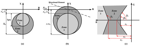
Figure 1.
The characteristics of traditional LOE relays including the R–X scheme (a), the scheme with DE (b) and scheme (c).
2.1.2. Offset Mho Relay Equipped with a Directional Element
This relay also uses two offset mho zones for LOE detection equipped with a directional element (DE), while the DE is intended to enhance the security of the relay in the face of the external close-in short circuit faults. Figure 1b illustrates the characteristic of such a relay. As shown, the relay setting depends on the reactance of the external power grid (). Similar to the simple scheme, the operation time delays for the first and second zones can be commonly selected as and [1]. However, this relay is still liable to mal-operate in the face of system disturbances [2].
2.2. Admittance Based Relay (G–B Scheme)
The main concept of LOE protection by the admittance based scheme is the mapping of generator capability limits from active-reactive power () plan to the (conductance-susceptance) plan [15,16]. Figure 1c shows the characteristic of the relay. Similar to the relay, time delays of and are respectively considered for the first and second zones. The conventional setting parameters of the scheme are as follows [16]:
3. LOE Modeling
To accomplish thorough LOE studies, a realistic representation of generator excitation system is needed. Two frequent forms of the generator models i.e., the dq and the PD models are available in the power grid simulation tools [14]. Indeed, the PD model is the basic representation of a synchronous generator in which the generator equations are dependent on the rotor position (θ), and this makes the model so complicated imposing large calculation burden to the simulation program. To simplify the PD model, the well-known Park transform is applied to it and yields the dq model [17,18]. In fact, in the dq model, the generator equations are independent of θ and the model is simplified, while the stator windings are transferred to the rotor reference frame [18]. However, it is not ideally suitable for realistic LOE studies [14].
The popular dq model, which exists in almost all common simulation software, e.g., EMTP and PSCAD, is appropriate for power network dynamic studies, but it has serious limitations to fulfill universal LOE studies [2]. On the contrary, the PD model, which is accessible in the RTDS simulator [19], is a much more appropriate tool to investigate the LOE phenomenon and effectively assess the LOE detection algorithms [14].
3.1. LOE Modeling by the Dq Model
The per-unit excitation voltage () and the mechanical power () are two inputs of the dq model and so, the LOE occurrence can only be applied by varying the . Figure 2 illustrates the common representation of dq model and the relevant structure to apply LOE events, where (pu) is the voltage injected from the model of the excitation system. The parameter k defines the operating modes, while , and , respectively, denote healthy operation, PLOE and CLOE (field short circuit) conditions. So, LOE modeling by employing the dq model is not very accurate and a low number of LOE events can be applied.
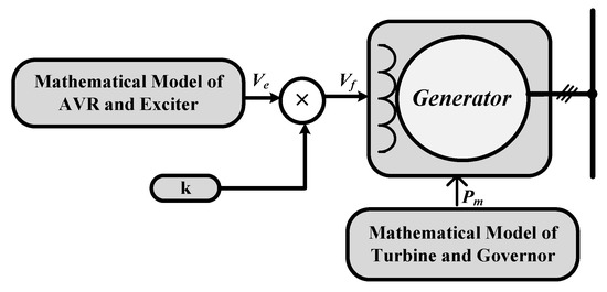
Figure 2.
Common structure of the dq model for LOE studies.
3.2. LOE Modeling by the PD Model
Against the dq model, both ends of the excitation winding are accessible in the PD model and so, a desired excitation circuit can be developed for the generator in order to perform realistic LOE studies [2].
In this paper, a realistic and frequent model of a power generation unit is established by employing the PD model to examine the LOE occurrence on the basis of IEEE standard [1]. Figure 3 illustrates the overall diagram of the sample studied system comprising a generator connected to an external grid via a unit transformer and a power transmission line. The generator excitation system comprises a three phase controlled static rectifier, manual voltage regulator (MVR), automatic voltage regulator (AVR), surge absorber and crowbar system, while such a excitation system is extensively utilized in the practical applications [20,21]. Table 1 introduces the components of the studied system.
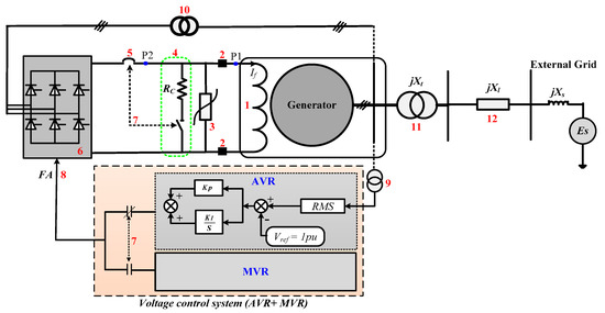
Figure 3.
The sample power generation system developed by using the phase domain (PD) model for thorough LOE studies.

Table 1.
Definitions of the studied system components.
Using such a system, different types of LOE events can be modeled in accordance with IEEE standard C37.102-2006 [1] as follows:
- Short circuit incidence for example at point P1, as Type-1.
- Open circuit incidence for example at point P1, as Type-2.
- Unintentional opening of AC/DC circuit breaker and crowbar system interlocked triggering, as Type-3.
- Open circuit event for example at point P2 and surge absorber self-activation to extinguish possible high voltages in the excitation winding, as Type-4.
- AVR failure and inaccurate change of voltage regulation system from AVR to MVR mode, as Type-5.
Regarding the fifth type, it is worth mentioning that such AVR malfunctions can be diagnosed by fault detection methods in the industrial excitation systems [21]. In such conditions, the MVR, which tracks the AVR output, takes the regulation of the excitation voltage to prevent abrupt changes in the generator output variables [2]. As a possible case, any problem in the tracking procedure may lead to a LOE condition. In this paper, a Type-5 event is regarded to model PLOE events, and the other types are intended as CLOE ones.
The AVR adjusts the firing angle () of the rectifier and the MVR follows its output. To model the PLOE, it is expected that the changeover from the AVR to the MVR mode is accomplished after AVR failure, while the MVR cannot follow the precise value of the AVR output parameter. The output DC voltage () of a controlled three phase rectifier (with as the line to neutral input voltage) is presented as [2]:
Obviously, the higher amounts of will make lower . So, it is expected that after such a changeover, the MVR provides higher values of so that a PLOE event can be anticipated. Assuming as the preliminary steady-state value of FA, its new value to create a PLOE condition is defined as , while () is the interchanging error.
4. Simulation Studies
4.1. Relays Operating Procedure
The operating characteristics of the traditional LOE relays are presented in Section 2. Figure 4 shows the general operating procedure of such relays. In this study, generator three-phase voltage and current signals are sampled with frequency sampling of 1200 Hz. A low pass anti-aliasing filter with cutoff frequency of 600 Hz is employed to eliminate the probable high frequency components. Then, discrete Fourier transform (DFT) is used to estimate the related voltage and current phasors . After that, impedance and admittance phasors are calculated. Finally, the impedance/admittance trajectories are compared with the relay protective zones in plan to make a decision about LOE occurrence.
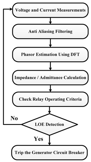
Figure 4.
General operating procedure of the traditional LOE relays.
4.2. System Under Study
The studied power system is depicted in Figure 3, where a , generator is connected to an external grid () via a unit transformer and one power transmission line. More details about the studied system components can be found in [4].
In the following, the traditional LOE relays performances are explored through various LOE and SPS case studies.
4.3. CLOE Case Studies
4.3.1. CLOE Failures in Heavy Loaded Generator
In this case, the generator initially delivers to the system, while all types of mentioned CLOE events are applied at through single scenarios. Figure 5 (first column) depicts the variations of and during such CLOE events. It is obvious that the generator dynamic behavior differs significantly during the mentioned CLOE events, while the generator experiences a loss of synchronism (LOS) phenomenon at different instants. It should be noted that after LOS occurrence, the generator parameters such as and changes oscillatory, as can be seen in Figure 5. Moreover, Figure 6 illustrates the variations of generator field current during the mentioned LOE events in generator high loading operation. As can be seen, during Type-2 failure, becomes instantaneously zero, while during the other failures and after a gradual decrease, circulates in the field winding as an AC current with the generator slip frequency.
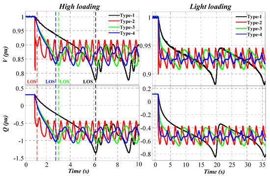
Figure 5.
variations during CLOE events in generator heavy loading (right column) and light loading (left column) conditions.
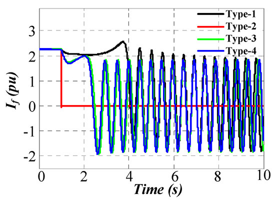
Figure 6.
Variations during CLOE events in generator heavy loading.
Figure 7 (first row) shows the performances of the traditional relays facing such events. As shown, all relays can dependably diagnose such events during a generator’s heavy loading operation with detection time of .
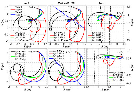
Figure 7.
The performances of the traditional schemes during different CLOE events in the generator heavy loading (first row) and light loading (second row) operations; including scheme (left), scheme with a directional element (DE) (middle) and scheme (right).
4.3.2. CLOE Failures in Light Loaded Generator
In this case, the initial loading of the generator is . Similarly to the previous case, all types of CLOE failures are executed at . Figure 5 (second column) shows the variations of and . As anticipated, the generator dynamic behavior differs during the mentioned events. As can be found from Figure 5, the generator dynamics during each CLOE failure in heavy loading operation are much faster than those in the light loading operation, and the LOS phenomenon occurs in earlier instants. Moreover, the relays’ performances are illustrated in Figure 7 (second row), where all of them are able to diagnose such events.
4.3.3. Comprehensive Results for CLOE Events
Table 2 contains the achieved results regarding the CLOE detection by the traditional relays during different loading operations comprising the above-studied cases. From the obtained results, some general points can be concluded as the following:
Table 2.
The traditional relays performances during CLOE events in different loading operations.
- All the relays dependably cover all types of CLOE failures.
- The scheme with DE exhibits faster performance than the other schemes.
4.4. PLOE Case Studies
4.4.1. PLOE Events in Heavy Loaded Generator
In this scenario, the generator preliminary loading is and the is equal to 67.6. A changeover from the AVR to the MVR mode is made at , and the MVR adjusts the new value of FA as . Figure 8 (first column) illustrates the variation of and during PLOE events and for different values of . It is clear that the higher values of leading to faster generator dynamics and earlier LOS occurrence.
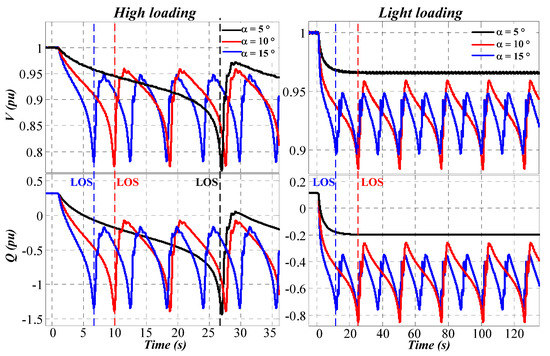
Figure 8.
and variations during (PLOE failures in heavy loading (right column) and light loading (left column) conditions.
Figure 9 (first row) illustrates the performances of the LOE relays facing such PLOE failures, while all schemes can dependably detect the mentioned events. It is clear that larger values of leads to faster PLOE detection.
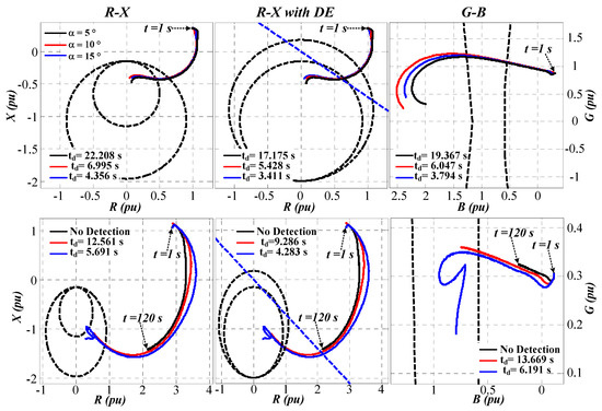
Figure 9.
Performances of the traditional schemes during different PLOE failures in heavy loading (first row) and light loading (second row) conditions; including R–X scheme (first column), R–X scheme with DE (second column) and G–B scheme (third column).
4.4.2. PLOE Events in Light Loaded Generator
In this scenario, the generator initially injects into the system and the is equal to 75.8°. Figure 8 (second column) illustrates the variation of and during PLOE events for different values of . As can be seen and compared to the previous case, the loading level significantly affects the generator dynamic behavior for specified values of . Interestingly, LOS does not occur for in light loading condition, and the generator continues working with a reduced level of and a leading power factor, changed from the initial lagging one.
Figure 9 (second row) illustrates the LOE relays performances in the face of such PLOE failures in light loading condition. As can be seen, the impedance and admittance trajectories do not enter the protective zones for and so the relays do not identify any LOE condition. As stated before, the generator reaches a new operating point in this condition without experiencing LOS and there is no need for the relay operation. However, such a new operating point should be monitored by the power plant operators after AVR to MVR interchange in order to avoid any potential damages to the generator.
Table 3 summarizes the obtained results regarding the PLOE detection by the traditional LOE relays during various loading operations. As can be seen, the R–X scheme with DE detects PLOE conditions faster than both the other schemes, while their detection times are almost in a same range.
Table 3.
PLOE detection by traditional schemes in different loading levels.
4.5. SPS Conditions
The LOE detection relays are susceptible to mal-operation in the face of power system external events such as SPS phenomenon, while the probability of such mal-operations rises when the generator draws from the [22]. So, special attention must be paid to the performances of the traditional relays facing such phenomena.
4.5.1. First SPS Scenario
In this scenario, the generator initially delivers to the system. To create an SPS condition, a symmetrical short circuit fault is exerted on the generator terminal at , while the fault is cleared after . Then, the generator confronts an SPS phenomenon. Figure 10 (first column) shows the behavior of the traditional relays in the face of such condition. As can be seen, the impedance and admittance trajectories come into the relays protective zones during such condition, though the relays stay secure and do not exhibit mal-operations. Indeed, the typically designated time delays are enough to prevent mal-operations during this particular case.
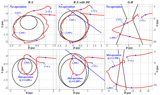
Figure 10.
The behaviors of the traditional LOE detection schemes during first stable power swing (SPS) scenario (first row) and the second scenario (second row).
4.5.2. Second SPS Scenario
In this scenario, the SPS condition is created similar to the previous one, but the generator initial loading is and the short circuit fault is cleared after . Figure 10 (second column) shows the behaviors of the different schemes during such a SPS case. As shown, all the relays cannot distinguish such SPS condition from LOE occurrence and cause undesirable generator tripping. Therefore, as mentioned before, special importance should be considered for time-delay settings of the traditional LOE protection relays, and careful power swing studies are recommended to appropriately define such time-delay settings [22,23].
5. Conclusions
In this paper, the performances of the traditional LOE protection relays are examined through simulation case studies in the RTDS. To achieve this goal, a realistic power generation unit comprising a common excitation system is developed by using the PD model of the synchronous generator, while such a model allows for simulating different types of CLOE and PLOE events based on IEEE Standard.
Simulation cases included different CLOE and PLOE events and two SPS scenarios, while the achieved results show that all methods can dependably detect various types of CLOE and PLOE failures. However, the relays might not act during some PLOE cases (resulting from AVR to MVR interchanging procedure) in which the generator does not experience LOS and reaches a new steady state operating point. In such a condition, the long-term operation of the generator should be monitored by the power plants operators.
It is also shown that the traditional LOE protection relays might malfunction facing the SPS phenomenon. So, attention should be given to appropriately choosing the time-settings of the relays so that the probability of such mal-operations can be diminished.
In summary, the main results of this paper are as follows:
- Employing a realistic model to study the LOE phenomenon based on IEEE standard and then investigating the performances of traditional LOE protection relays.
- The traditional LOE detection schemes can reliably diagnose all CLOE failures; however, they might not detect some PLOE, in which the generator reaches a new stable operating point.
- The impedance-based scheme equipped with a directional element acts faster than the other schemes facing the same LOE events.
- The traditional schemes might exhibit mal-operation during system disturbances, and so special attention should be paid to their time delay settings.
Author Contributions
The main idea was proposed by A.H. Abbas also did the simulation studies and prepared the first draft of the paper. C.L.B. and F.M.F.d.S. reviewed the paper several times and had lots of technical and writing comments during the paper preparation procedure. All authors have read and agreed to the published version of the manuscript.
Funding
This research received no external funding.
Conflicts of Interest
The authors declare no conflict of interest.
References
- IEEE Standard C37.102-2006. IEEE Guide for AC Generator Protection; IEEE Standard: Piscataway, NJ, USA, 2006. [Google Scholar]
- Hasani, A.; Haghjoo, F.; Bak, C.L.; da Silva, F.F. Synchronous Generator LOE Protection Using a Detailed Model Based on IEEE Standard C37.102-2006. In Proceedings of the 2019 IEEE International Conference on Environment and Electrical Engineering, Genoa, Italy, 10–14 June 2019. [Google Scholar]
- Lv, Y.; Gao, Y.; Zhang, J.; Deng, C.H.; Hou, S.H. Symmetrical Loss of Excitation Fault Diagnosis in an Asynchronized High-Voltage Generator. Energies 2019, 11, 3054. [Google Scholar] [CrossRef]
- Hasani, A.; Haghjoo, F.; Bak, C.L.; da Silva, F.F. Performance Evaluation of Some Industrial Loss of Field Protection Schemes Using a Realistic Model in The RTDS. In Proceedings of the 2019 IEEE International Conference on Environment, Genoa, Italy, 10–14 June 2019. [Google Scholar]
- Hasani, A.; Haghjoo, F.; da Silva, F.F.; Bak, C.L. A Current-Based Differential Technique to detect Loss of field in Synchronous generators. IEEE Trans. Power Deliv. 2019, 35, 514–522. [Google Scholar] [CrossRef]
- Hasani, A.; Haghjoo, F.; da Silva, F.F.; Bak, C.L. A DC Power-Based Scheme to Detect Loss of Field in Synchronous Generators. In Proceedings of the 2019 IEEE International Conference on Environment and Electrical Engineering, Genoa, Italy, 10–14 June 2019. [Google Scholar]
- Mahamedi, B.; Zhu, J.; Hashemi, S.M. A setting free approach to detecting loss of field in synchronous generators. IEEE Trans. Power Deliv. 2016, 31, 2270–2278. [Google Scholar] [CrossRef]
- Noroozi, N.; Alinejad-Beromi, Y.; Yaghobi, H. Fast approach to detec generator loss of excitation based on reactive power variation. IET Gener. Transm. Distrib. 2019, 13, 453–460. [Google Scholar] [CrossRef]
- Abedini, M.; Sanaye-Pasand, M.; Davarpanah, M.; Iravani, R. A loss of field detection relay based on rotor signals estimation. IEEE Trans. Power Deliv. 2018, 33, 1429–1438. [Google Scholar] [CrossRef]
- Abedini, M.; Sanaye-Pasand, M.; Davarpanah, M. Flux linkage estimation based loss of excitation relay for synchronous generator. IET Gener. Transm. Distrib. 2017, 11, 280–288. [Google Scholar] [CrossRef]
- Abedini, M.; Sanaye-Pasand, M.; Davarpanah, M. An Analytical Approach to Detect Generator Loss of Excitation Based on Internal Voltage Calculation. IEEE Trans. Power Deliv. 2017, 32, 2329–2338. [Google Scholar] [CrossRef]
- Yaghobi, H.; Mortazavi, H. A novel method to prevent incorrect operation of synchronous generator loss of excitation relay during and after different external faults. Int. Trans. Electr. Energy Syst. 2015, 25, 1717–1735. [Google Scholar] [CrossRef]
- Yaghobi, H.; Mortazavi, H.; Ansari, K.; Mashhadi, H.R. Study on application of flux linkage of synchronous generator for loss of excitation detection. Int. Trans. Electr. Energy Syst. 2013, 23, 802–817. [Google Scholar] [CrossRef]
- Hasani, A.; Haghjoo, F.; da Silva, F.F.; Bak, C.L. Synchronous generator loss of field protection: A real-time realistic framework and assessment of some recently proposed methods. IEEE Trans. Power Deliv. 2019, 34, 971–979. [Google Scholar] [CrossRef]
- Alla, M.; Guzman, A.; Finney, D.; Fischer, N. Capability Curve-Based Generator Protection Minimizes Generator Stress and Maintains Power System Stability. In Proceedings of the 45th Annual Western Protective Relay Conference, Spokane, WA, USA, 15–17 October 2018. [Google Scholar]
- Hermann, H.J.; Gao, D. Under-Excitation Protection Based on Admittance Measurement Excellent Adaptation on Capability Curves. In Proceedings of the 1st International Conference on Hydropower Technology and Key equipment, Beijing, China, 27–30 October 2006. [Google Scholar]
- Boldea, I. Synchronous Generators, 2nd ed.; CRC Press: Boca Raton, FL, USA, 2015. [Google Scholar]
- Chow, J.H.; Sanchez-Gasca, J.J. Power System Modeling, Computation, and Control; Wiley—IEEE: Hoboken, NJ, USA, 2019. [Google Scholar]
- RTDS Technologies. Real-Time-Digital-Simulator User’s Manual; RTDS Technologies INC: Winnipeg, MB, Canada, 2019. [Google Scholar]
- THYRIPOL. Static Excitation Systems for the Excitation and Voltage Regulation of Synchronous Machines; Siemens AG: Munich, Germany, 2015. [Google Scholar]
- Unitrol 6000 Static Excitation Systems; ABB: Zurich, Switzerland, 2015.
- Power Plant and Transmission System Protection Coordination; Rev. 1; NERC System Protection and Control Subcommittee: Washington, DC, USA, 2010.
- Hasani, A.; Haghjoo, F.; da Silva, F.F.; Bak, C.L. Loss of Field Protection of Synchronous Generator in a Realistic Framework Using RTDS. In Proceedings of the 2018 IEEE International Conference on Environment and Electrical Engineering and 2018 IEEE Industrial and Commercial Power Systems Europe (EEEIC/I&CPS Europe), Palermo, Italy, 12–15 June 2018. [Google Scholar]


Publisher’s Note: MDPI stays neutral with regard to jurisdictional claims in published maps and institutional affiliations. |
© 2020 by the authors. Licensee MDPI, Basel, Switzerland. This article is an open access article distributed under the terms and conditions of the Creative Commons Attribution (CC BY) license (http://creativecommons.org/licenses/by/4.0/).