Waste Heat Recovery from Diesel Engine Exhaust Using a Single-Screw Expander Organic Rankine Cycle System: Experimental Investigation of Exergy Destruction


 ,
,
Abstract
:
1. Introduction
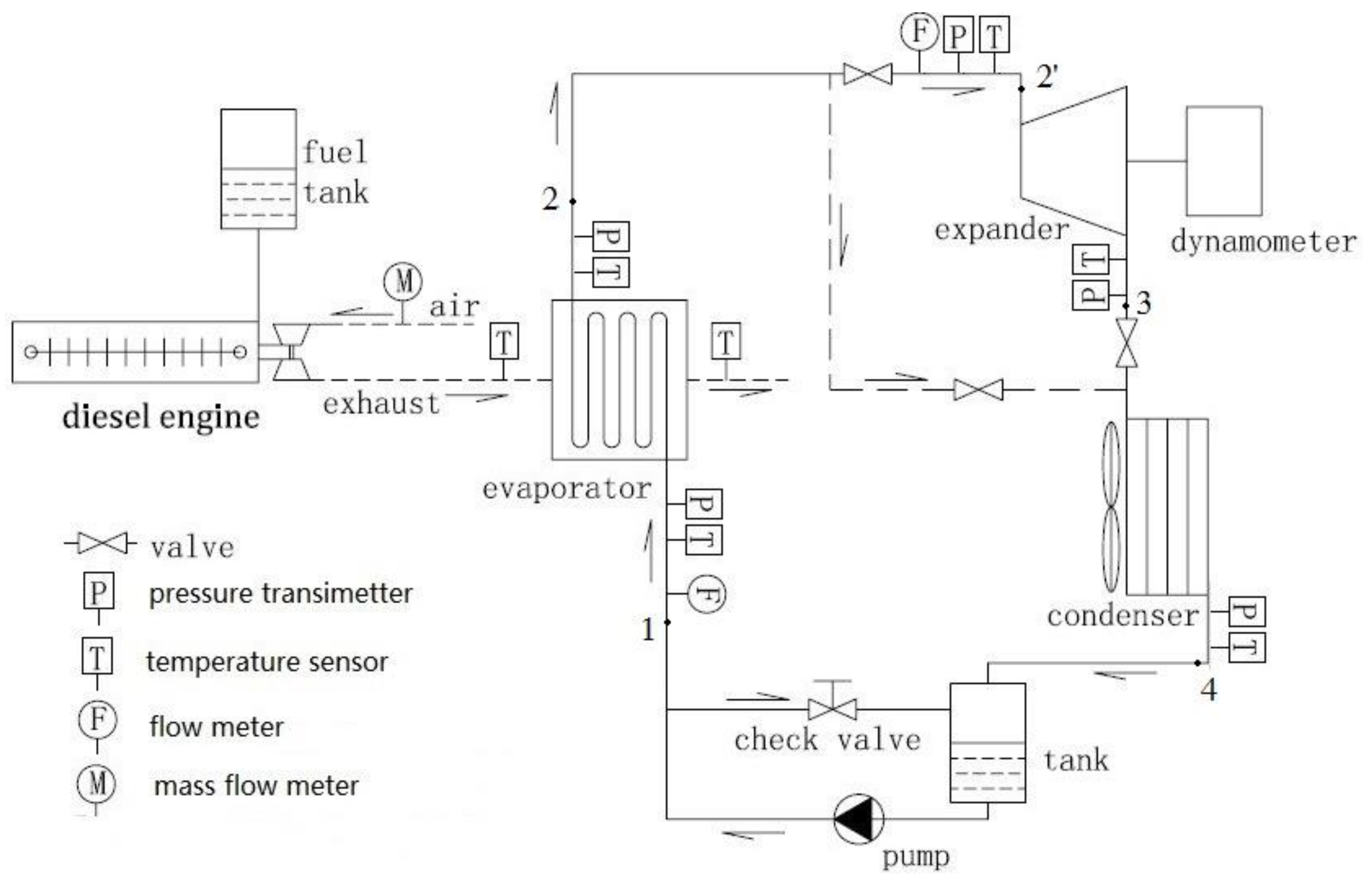
2. System Description and Test Rig
2.1. System Description
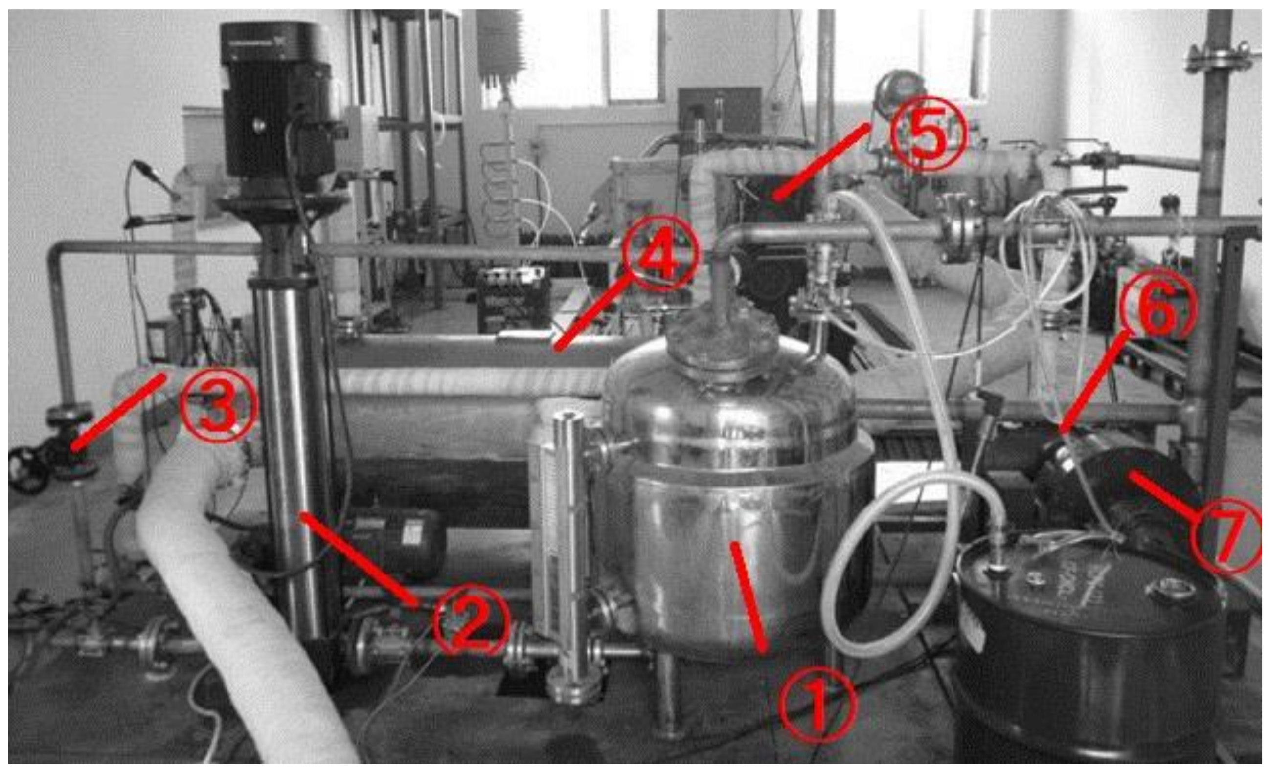
2.2. Experimental Test Rig
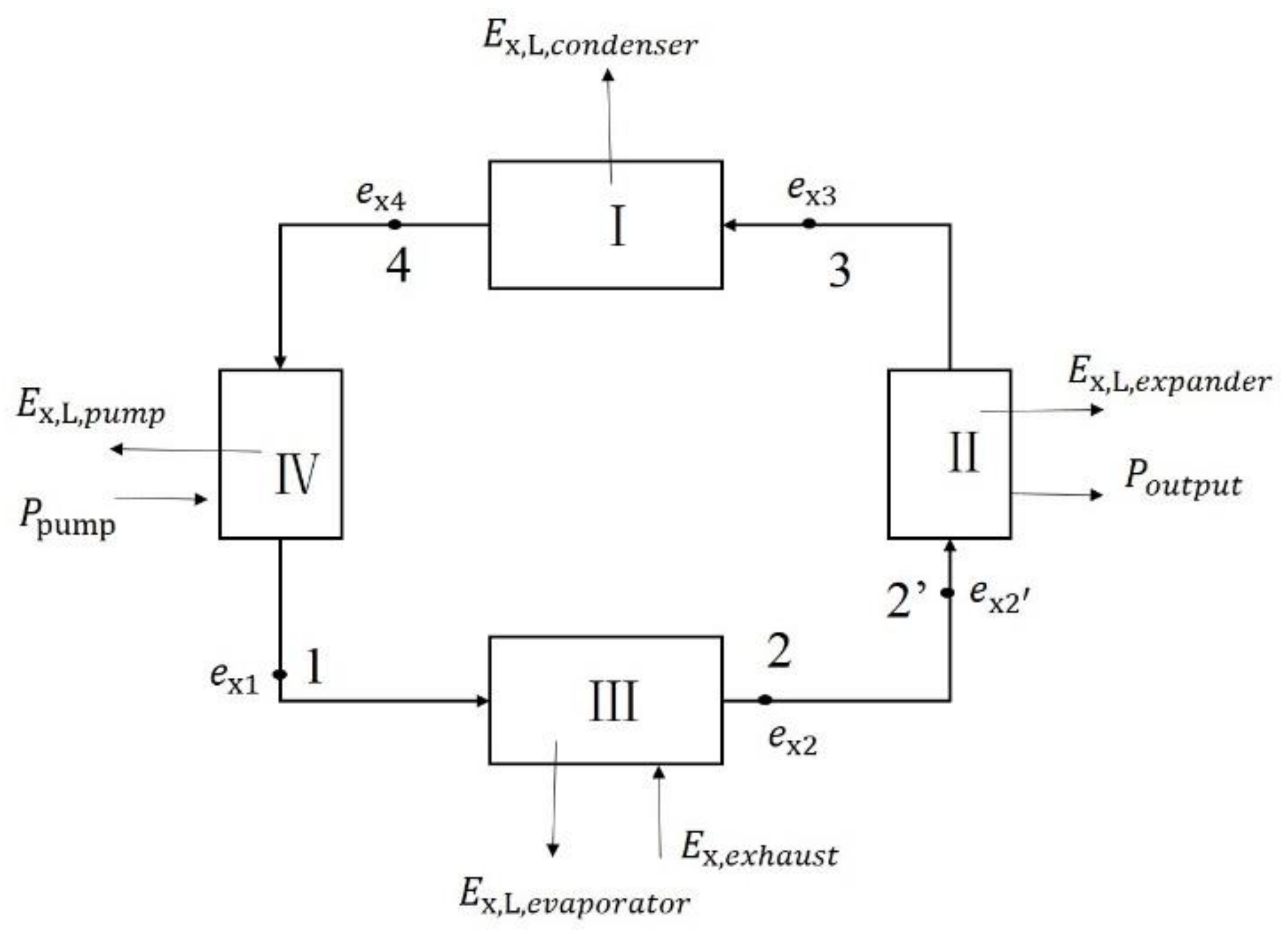
3. Data Processing
4. Results and Discussion
5. Conclusions
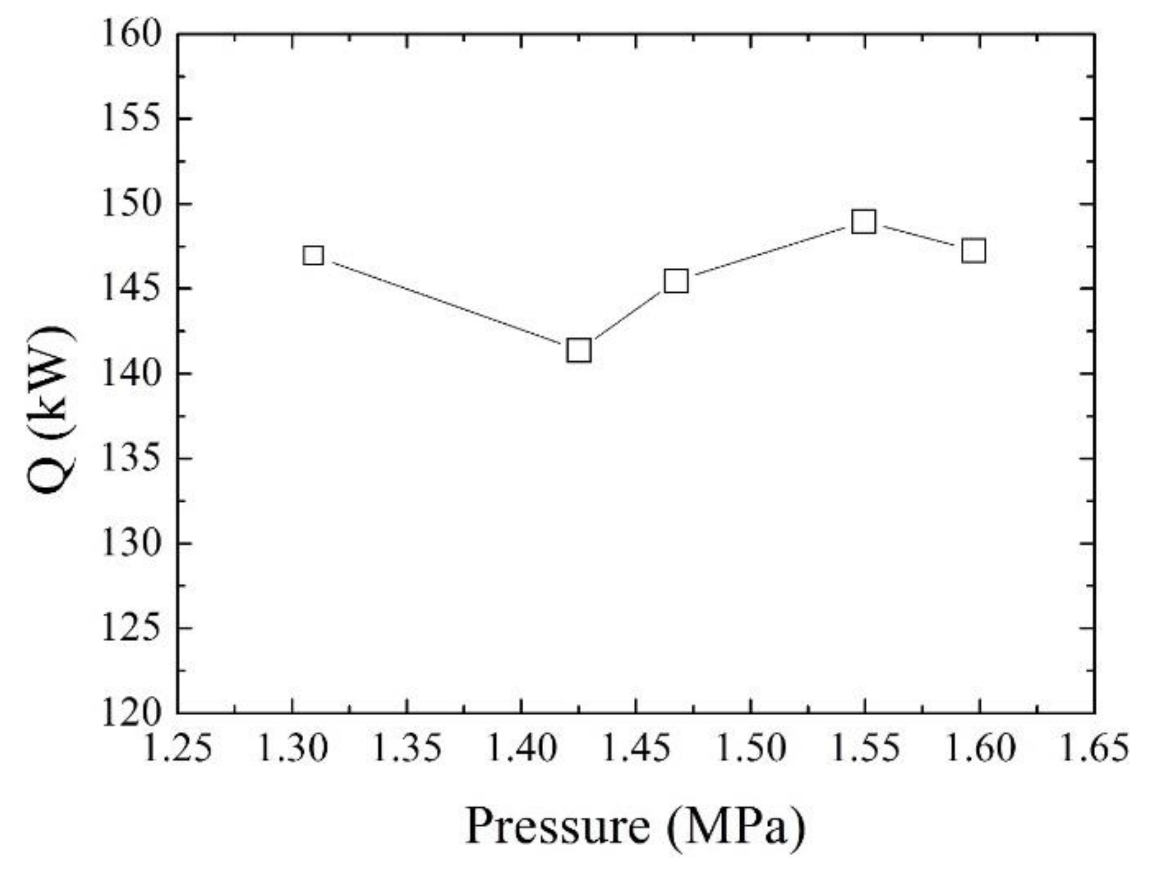
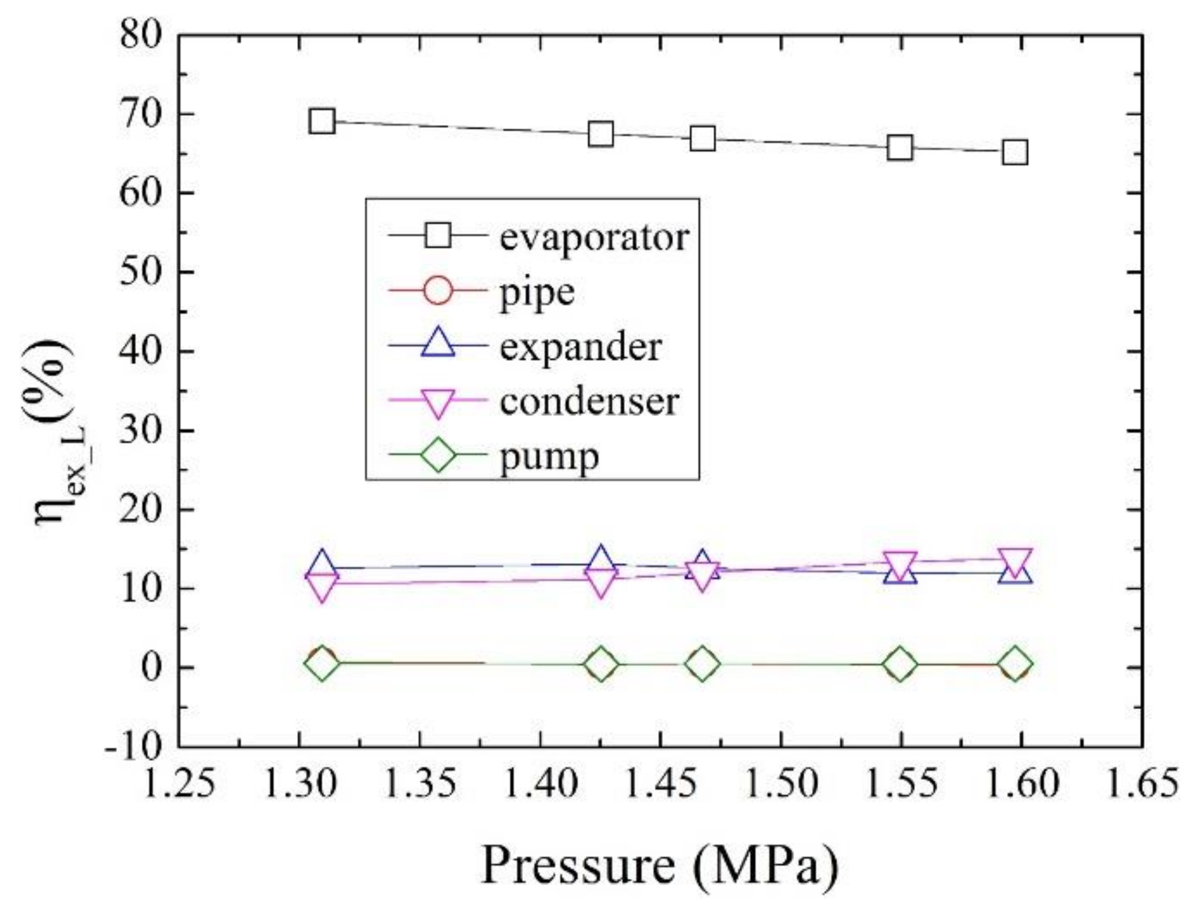
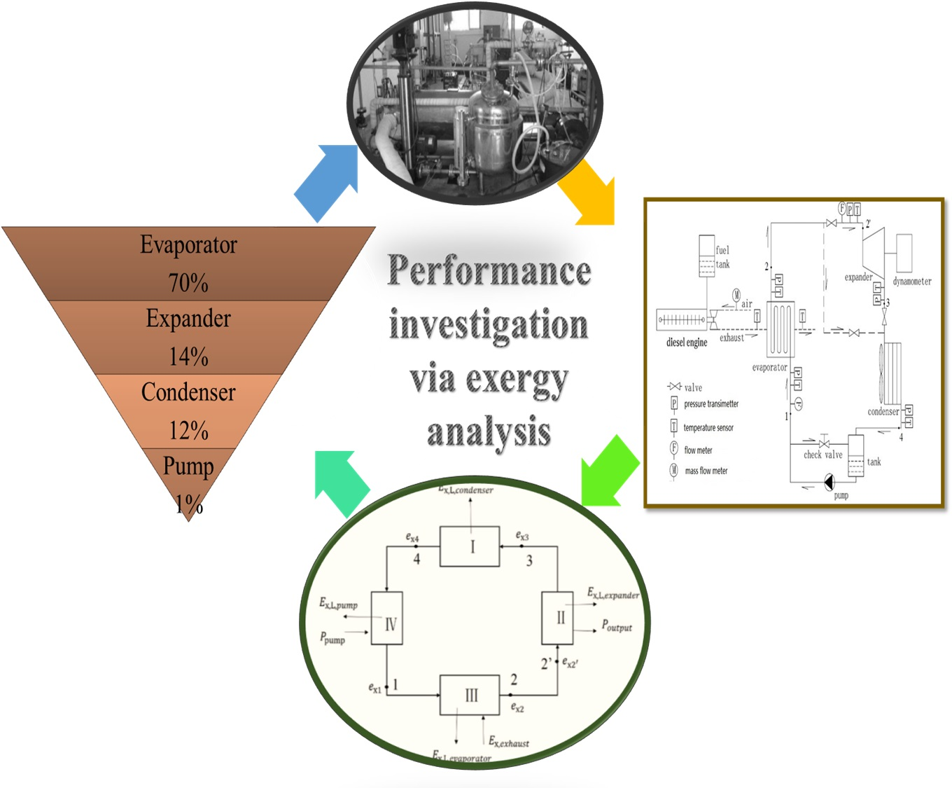
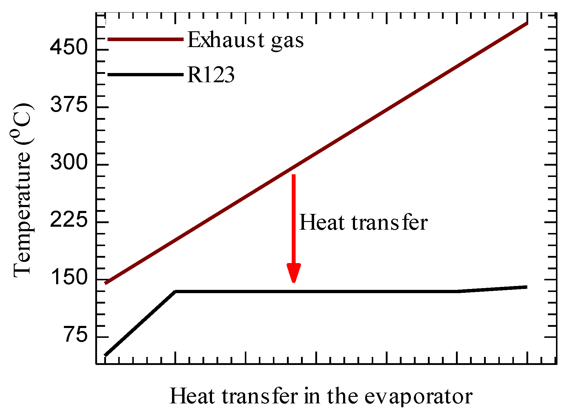
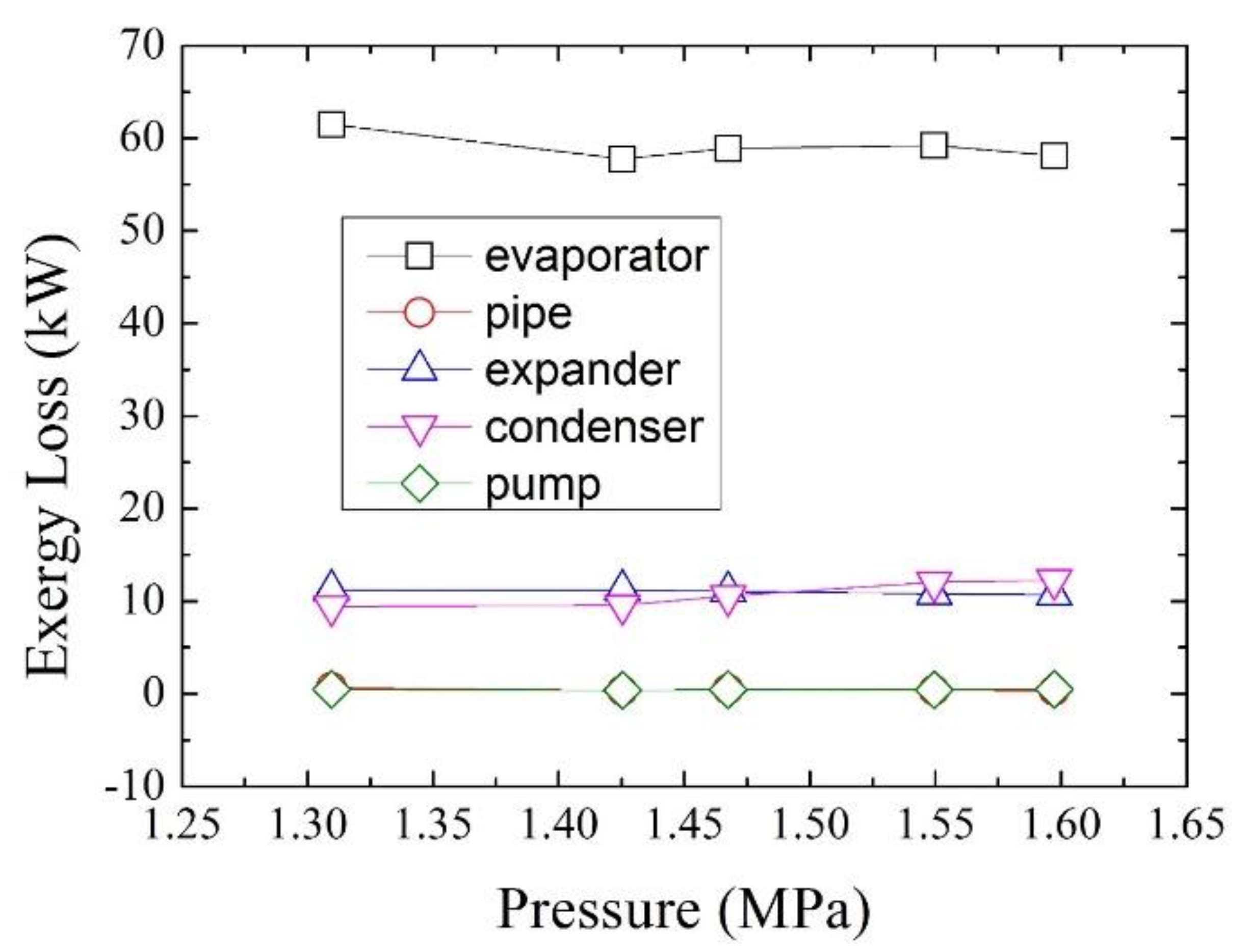
- The exergy losses of the evaporator are almost 60 kW at different evaporation pressures; the corresponding exergy loss rate is from 69.1% to 65.1% and accounts for the most of the total exergy loss rate.
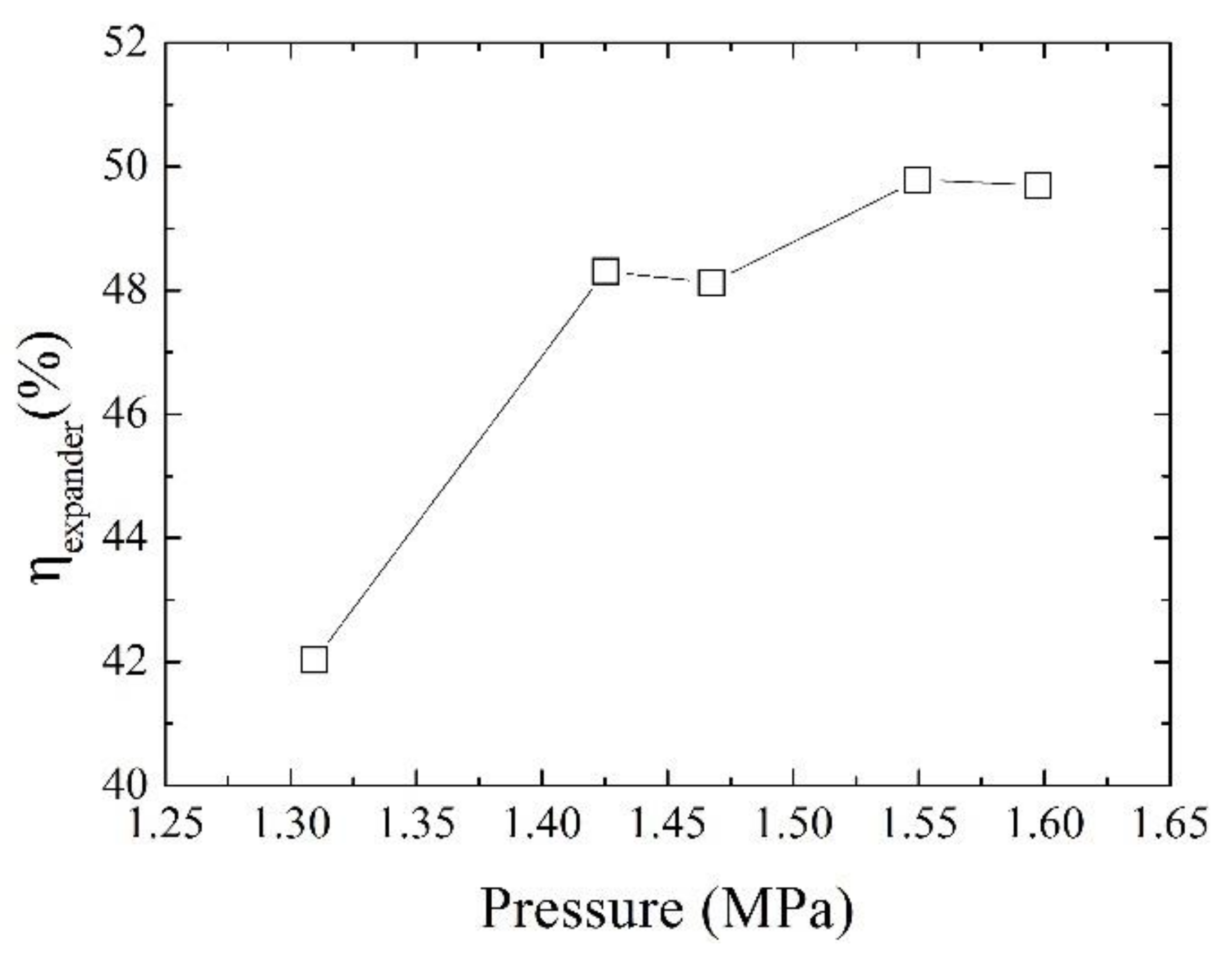
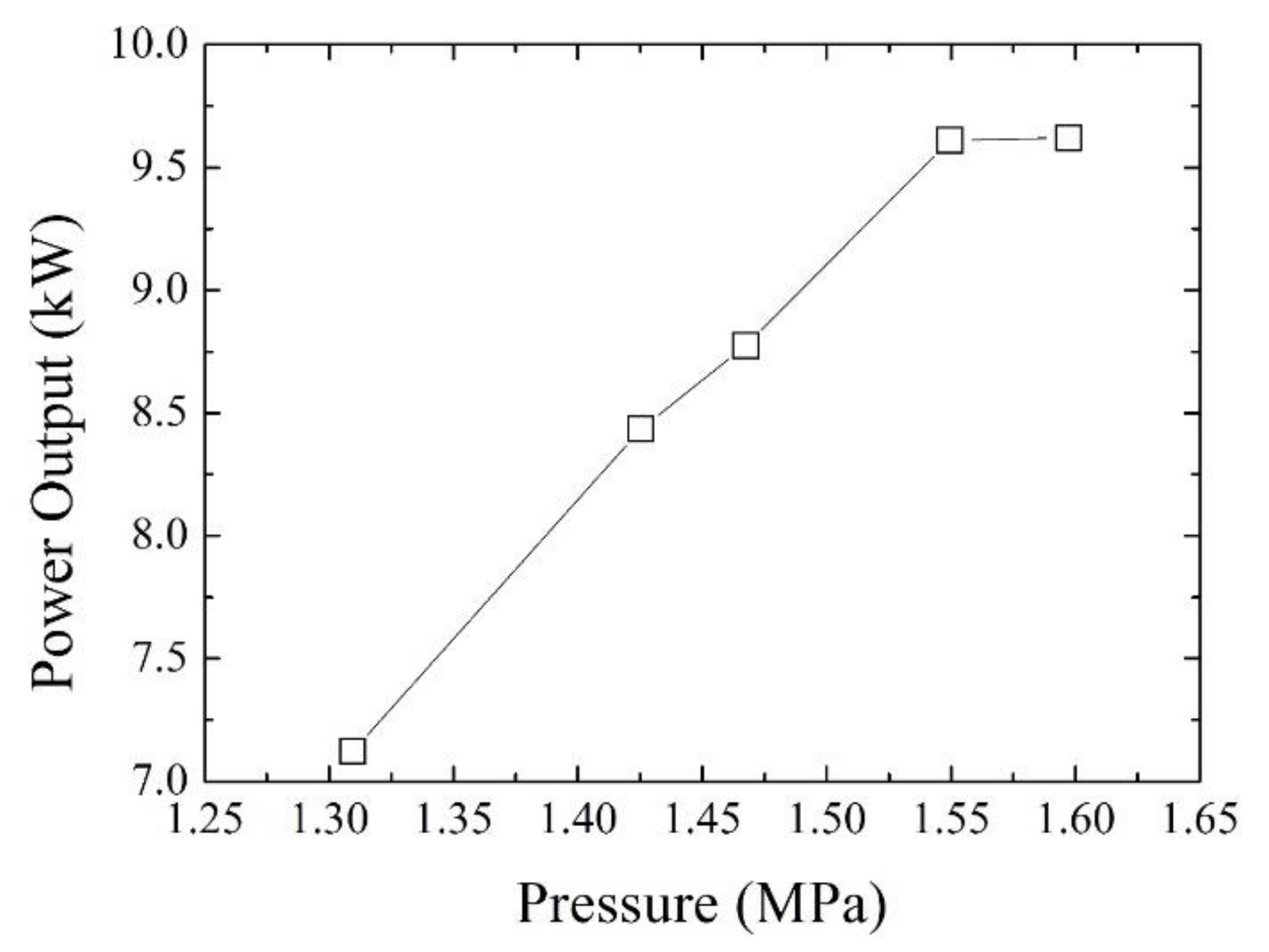
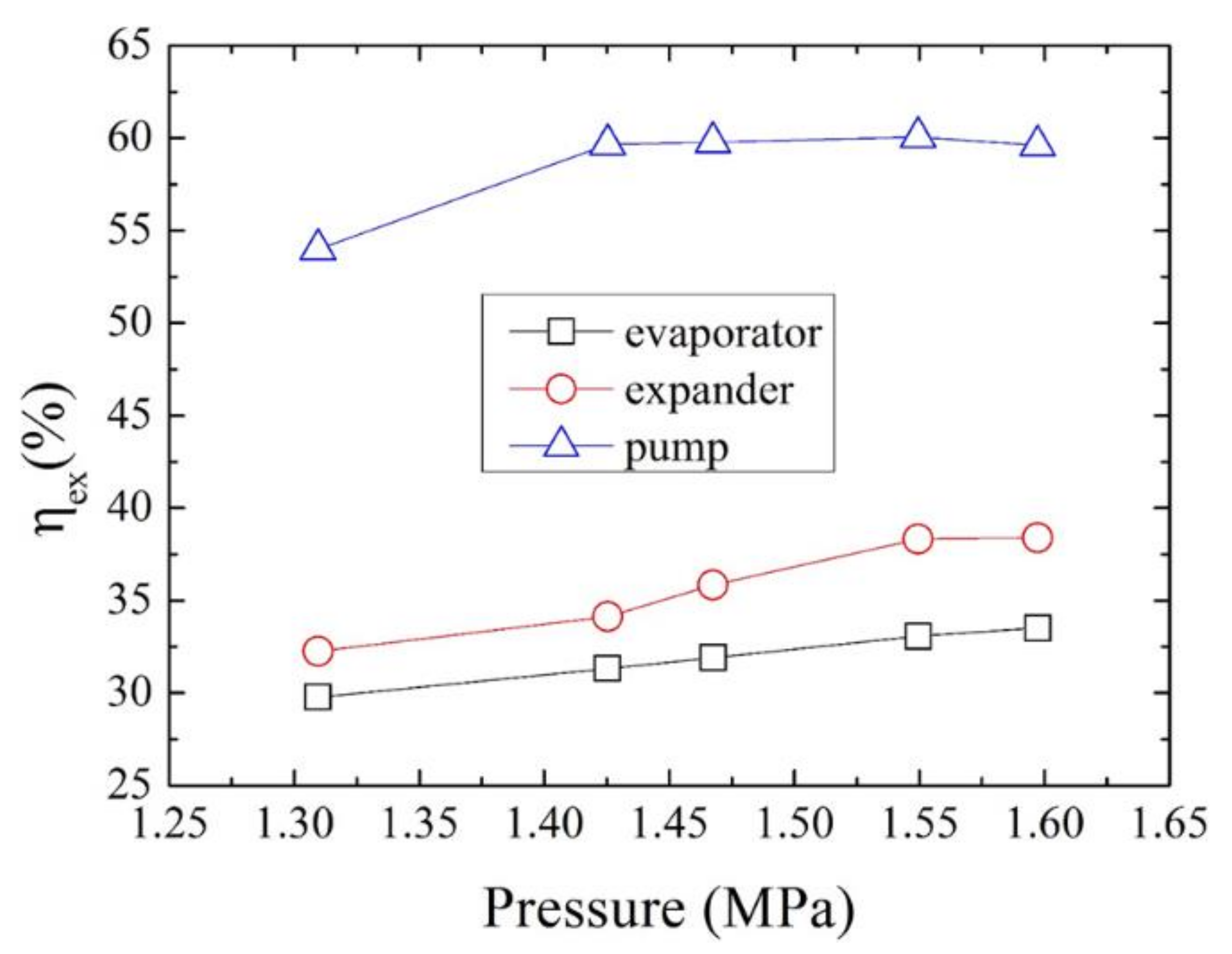
- The expander’s maximum shaft efficiency and exergetic efficiency are 49.8% and 38.4%, respectively. Increasing the performance of the expander can increase the power output, and then the system’s performance is increased also.
- The exergy losses and exergy loss rate of the pump and pipe are less than 0.5 kW and 1%, respectively, the effects of which on the system’s performance can be ignored.
Author Contributions
Funding
Conflicts of Interest
Appendix A
Appendix A.1. Evaporator
Appendix A.2. Pipe
Appendix A.3. Expander
Appendix A.4. Condenser
Appendix A.5. Pump
References
- Fatigati, F.; Bartolomeo, M.D.; Battista, D.D.; Cipollone, R. Experimental validation of a new modeling for the design optimization of a sliding vane rotary expander operating in an orc-based power unit. Energies 2020, 13, 4204. [Google Scholar] [CrossRef]
- Bull, J.; Buick, J.M.; Radulovic, J. Heat Exchanger Sizing for Organic Rankine Cycle. Energies 2020, 13, 3615. [Google Scholar] [CrossRef]
- Domingues, A.; Santos, H.; Costa, M. Analysis of vehicle exhaust waste heat recovery potential using a Rankine cycle. Energy 2013, 49, 71–85. [Google Scholar] [CrossRef]
- Yu, C.; Chau, K.T. Thermoelectric automotive waste heat energy recovery using maximum power point tracking. Energy Convers. Manag. 2009, 50, 1506–1512. [Google Scholar] [CrossRef]
- Wang, E.H.; Zhang, H.G.; Fan, B.Y.; Ouyang, M.G.; Zhao, Y.; Mu, Q.H. Study of working fluid selection of organic Rankine cycle (ORC) for engine waste heat recovery. Energy 2011, 36, 3406–3418. [Google Scholar] [CrossRef]
- Wang, S.; Yuan, Z.A. Hot water split-flow dual-pressure strategy to improve system performance for Organic Rankine Cycle. Energies 2020, 13, 3345. [Google Scholar] [CrossRef]
- Imran, M.; Haglind, F.; Lemort, V.; Meroni, A. Optimization of organic Rankine cycle power systems for waste heat recovery on heavy-duty vehicles considering the performance, cost, mass and volume of the system. Energy 2019, 180, 229–241. [Google Scholar] [CrossRef]
- Horst, T.A.; Tegethoff, W.; Eilts, P.; Koehler, J. Prediction of dynamic Rankine Cycle waste heat recovery performance and fuel saving potential in passenger car applications considering interactions with vehicles’ energy management. Energy Convers. Manag. 2014, 78, 438–451. [Google Scholar] [CrossRef]
- Zhang, Y.-Q.; Wu, Y.-T.; Xia, G.-D.; Ma, C.-F.; Ji, W.-N.; Liu, S.-W.; Yang, K.; Yang, F.-B. Development and experimental study on organic Rankine cycle system with single-screw expander for waste heat recovery from exhaust of diesel engine. Energy 2014, 77, 499–508. [Google Scholar] [CrossRef]
- Shi, L.; Shu, G.; Tian, H.; Deng, S. A review of modified Organic Rankine cycles (ORCs) for internal combustion engine waste heat recovery (ICE-WHR). Renew. Sustain. Energy Rev. 2018, 92, 95–110. [Google Scholar] [CrossRef]
- Zhang, W.; Wang, E.; Meng, F.; Zhang, F.; Zhao, C. Closed-loop PI control of an Organic Rankine Cycle for engine exhaust heat recovery. Energies 2020, 13, 3817. [Google Scholar] [CrossRef]
- Bin Wan Ramli, W.R.; Pesyridis, A.; Gohil, D.; Alshammari, F. Organic Rankine Cycle Waste Heat Recovery for Passenger Hybrid Electric Vehicles. Energies 2020, 13, 4532. [Google Scholar] [CrossRef]
- Bufi, E.A.; Camporeale, S.M.; Cinnella, P. Robust optimization of an Organic Rankine Cycle for heavy duty engine waste heat recovery. Energy Procedia 2017, 129, 66–73. [Google Scholar] [CrossRef]
- Yang, F.; Cho, H.; Zhang, H.; Zhang, J.; Wu, Y. Artificial neural network (ANN) based prediction and optimization of an organic Rankine cycle (ORC) for diesel engine waste heat recovery. Energy Convers. Manag. 2018, 164, 15–26. [Google Scholar] [CrossRef]
- Hajabdollahi, Z.; Hajabdollahi, F.; Tehrani, M.; Hajabdollahi, H. Thermo-economic environmental optimization of Organic Rankine Cycle for diesel waste heat recovery. Energy 2013, 63, 142–151. [Google Scholar] [CrossRef]
- Yang, M.H.; Yeh, R.H. Thermodynamic and economic performances optimization of an organic Rankine cycle system utilizing exhaust gas of a large marine diesel engine. Appl. Energy 2015, 149, 1–12. [Google Scholar] [CrossRef]
- Galindo, J.; Climent, H.; Dolz, V.; Royo-Pascual, L. Multi-objective optimization of a bottoming Organic Rankine Cycle (ORC) of gasoline engine using swash-plate expander. Energy Convers. Manag. 2016, 126, 1054–1065. [Google Scholar] [CrossRef]
- Wronski, J.; Imran, M.; Skovrup, M.J.; Haglind, F. Experimental and numerical analysis of a reciprocating piston expander with variable valve timing for small-scale organic Rankine cycle power systems. Appl. Energy 2019, 247, 403–416. [Google Scholar] [CrossRef]
- Imran, M.; Usman, M.; Park, B.-S.; Lee, D.-H. Volumetric expanders for low grade heat and waste heat recovery applications. Renew. Sustain. Energy Rev. 2016, 57, 1090–1109. [Google Scholar] [CrossRef]
- Imran, M.; Usman, M. Mathematical modelling for positive displacement expanders. In Positive Displacement Machines; Academic Press: New York, NY, USA, 2019; pp. 293–343. [Google Scholar]
- Wang, W.; Wu, Y.-T.; Ma, C.-F.; Liu, L.-D.; Yu, L. Preliminary experimental study of single screw expander prototype. Appl. Therm. Eng. 2011, 31, 18–88. [Google Scholar] [CrossRef]
- Lei, B.; Wang, W.; Wu, Y.-T.; Ma, C.-F.; Wang, J.-F.; Zhang, L.; Li, C.; Zhao, Y.-K.; Zhi, R.-P. Development and experimental study on a single screw expander integrated into an Organic Rankine Cycle. Energy 2016, 116, 43–52. [Google Scholar] [CrossRef]
- Muhammad, H.A.; Lee, B.; Sultan, H.; Imran, M.; Baik, Y.-J. Advance thermodynamic analysis of a CO2 compression system using heat-pump for CCS. In Proceedings of the ECOS 2020—33rd International Conference on Efficiency, Cost, Optimization, Simulation and Environmental Impact of Energy Systems, Osaka, Japan, 29 June–3 July 2020; Available online: https://publications.aston.ac.uk/id/eprint/41661/1/Conference_paper_2.pdf (accessed on 1 September 2020).
- Lazzaretto, A.; Tsatsaronis, G. SPECO: A systematic and general methodology for calculating efficiencies and costs in thermal systems. Energy 2006, 31, 9–89. [Google Scholar] [CrossRef]
- Ahamed, J.U.; Saidur, R.; Masjuki, H.H. A review on exergy analysis of vapor compression refrigeration system. Renew. Sustain. Energy Rev. 2011, 15, 1593–1600. [Google Scholar] [CrossRef]


| Parameters | Values |
|---|---|
| ORC working fluid | R123 |
| Compressor and turbine isentropic efficiency | 0.80 |
| Heat source temperature | 485 °C |
| Maximum heat available | 248 kW |
| ORC evaporation pressure | 1300—1600 kPa |
| Condensing temperature | 48.7 ∼ 55.4 °C |
| Reference state (To and Po) | 35 °C/101 kPa |
| Component | Characteristics |
|---|---|
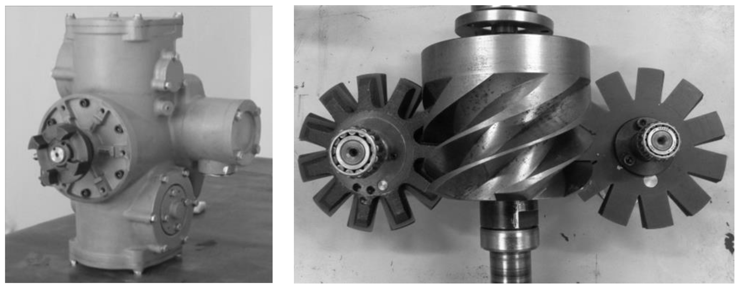
| Expander | Single-screw expander with CP type |
| Diameter of screw and gaterotor: 155 × 10−3 m | |
| Center distance: 124 × 10−3 m | |
| Grave number of screws: 6 | |
| Tooth number of gaterotor: 11 | |
| Evaporator | Shell and tube heat exchanger with spiral titanium tube and baffles |
| Overall dimensions: Φ 500 × 10−3 m × 1500 × 10−3 m | |
| Heat exchange area: 12 m2 | |
| Heat input capacity: 152 kW | |
| Condenser | Aluminum multi-channel parallel type condenser with 2 tube sides |
| Overall dimensions: (980 × 10−3 m) × (980 × 10−3 m) × (1255 × 10−3 m) | |
| Heat transfer area in air side: 90 m2 | |
| Heat rejection capacity: 150 kW | |
| Pump | GRUNDFOS multi-stage centrifugal pump: CR5-32 |
| Designed volume flow: 2.98 m3/h | |
| Designed head: 205 m |
| Parameters | Instrument | Accuracy | Full Scale |
|---|---|---|---|
| Temperature | PT100 | ±0.5 °C | −80 ∼ 300 °C |
| N-type | ±1.5 °C | 0 ∼ 800 °C | |
| Pressure | SMP131 | ±0.5% | 0 ∼ 2 MPa |
| Mass flow rate | Rotameter of H250 | ±1.0% | 25 ∼ 100 L/min |
| Oil consumption meter of FC2210 | ±0.4% | 0.1 ∼ 2 kg/min | |
| Thermal gas mass flow meter of 20N150 | ±1% | 0 ∼ 2400 kg/h | |
| Torque | GW40 eddy current dynamometer | ±0.2% | 0 ∼ 160 N × m |
| Rotational speed | GW40 eddy current dynamometer | ±1 rpm | 0 ∼ 10,000 rpm |
Publisher’s Note: MDPI stays neutral with regard to jurisdictional claims in published maps and institutional affiliations. |
© 2020 by the authors. Licensee MDPI, Basel, Switzerland. This article is an open access article distributed under the terms and conditions of the Creative Commons Attribution (CC BY) license (http://creativecommons.org/licenses/by/4.0/).
Share and Cite
Zhang, Y.; Lei, B.; Masaud, Z.; Imran, M.; Wu, Y.; Liu, J.; Qin, X.; Muhammad, H.A. Waste Heat Recovery from Diesel Engine Exhaust Using a Single-Screw Expander Organic Rankine Cycle System: Experimental Investigation of Exergy Destruction. Energies 2020, 13, 5914. https://doi.org/10.3390/en13225914
Zhang Y, Lei B, Masaud Z, Imran M, Wu Y, Liu J, Qin X, Muhammad HA. Waste Heat Recovery from Diesel Engine Exhaust Using a Single-Screw Expander Organic Rankine Cycle System: Experimental Investigation of Exergy Destruction. Energies. 2020; 13(22):5914. https://doi.org/10.3390/en13225914
Chicago/Turabian StyleZhang, Yeqiang, Biao Lei, Zubair Masaud, Muhammad Imran, Yuting Wu, Jinping Liu, Xiaoding Qin, and Hafiz Ali Muhammad. 2020. "Waste Heat Recovery from Diesel Engine Exhaust Using a Single-Screw Expander Organic Rankine Cycle System: Experimental Investigation of Exergy Destruction" Energies 13, no. 22: 5914. https://doi.org/10.3390/en13225914
APA StyleZhang, Y., Lei, B., Masaud, Z., Imran, M., Wu, Y., Liu, J., Qin, X., & Muhammad, H. A. (2020). Waste Heat Recovery from Diesel Engine Exhaust Using a Single-Screw Expander Organic Rankine Cycle System: Experimental Investigation of Exergy Destruction. Energies, 13(22), 5914. https://doi.org/10.3390/en13225914