Article

Magnetic Coupling for a 10 kW Tidal Current Turbine: Design and Small Scale Experiments

1
Korea Maritime & Ocean University Research Institute of Maritime Industry, Korea Maritime and Ocean University, Busan 49112, Korea
2
Department of Mechanical Engineering, Graduate School, Korea Maritime and Ocean University, Busan 49112, Korea
3
Energy Environment Center, Busan, Korea Marine Equipment Research Institute, Busan 49112, Korea
4
Korea Division of Mechanical Engineering, Korea Maritime and Ocean University, Busan 49112, Korea
*
Author to whom correspondence should be addressed.
Energies 2020, 13(21), 5725; https://doi.org/10.3390/en13215725
Submission received: 14 September 2020 / Revised: 30 October 2020 / Accepted: 30 October 2020 / Published: 2 November 2020
(This article belongs to the Special Issue Wave and Tidal Energy 2020)

Abstract

:
This paper presents a coupling design that improves water tightness of a marine current turbine (MCT). The coupling is numerically analyzed and incorporated into the design of an MCT from a previous study. The performance of the MCT with the magnetic coupling is compared to the previous results in small scale turbine experiments. The results show that the new design is water tight and has lower mechanical losses when compared with previous results. The new turbine has increased maximum power output (from 116 W to 122 W) and hydrodynamic coefficient of power (Previously 0.45 to 0.46). Using these results, the coupling design is scaled for a 10 kW MCT and further analyzed by finite element analysis. The results obtained show that the magnetic coupling is capable of withstanding the combined weight of the hub and blade assembly. The results in this study will be used for developing a prototype for deployment in real seas.

1. Introduction

In 2019, South Korea launched its Third Energy Master Plan, which endeavors to achieve sustainable growth and quality of life through energy transition. Among the steps outlined in the plan, the Korean Government has set the goal of reaching 30–35% of power generation to be produced by renewable energy by 2040 [1]. Park [2] provided analysis of the potential solar or wind resources on 17 cities in Korea using a micro-grid analysis and optimization software, Hybrid Optimization of Multiple Energy Resources (HOMER).
In addition to the solar and wind resources in Korea, there is continuing interest in the potent tidal current energy in Korea’s coastal region near the Yellow Sea. Kim et al. [3] highlighted observational data and numerical models used to estimate the output at several candidate sites. In Byun et al. [4], in-situ observation data show a large concentration of high energy density sites near coastal regions in the Jeonnam province. Hwang and Chul [5] conducted numerical simulations of water circulation on observational data provided by the Korean Hydrographic and Oceanographic Agency. Their results also coincide with the other studies that show sites, such as Uldolmok and Maenggol, as having sufficient potential for tidal current energy.
At one of the potential sites, Uldolmok, Dong et al. [6] highlighted the Uldolmok Tidal Current Power Pilot Plant that was commissioned in 2009. The pilot plant serves as a sea test facility for tidal current energy. A turbine, with an installed capacity of 1 MW, is being utilized for research. Furthermore, the Korea Institute of Ocean Science and Technology (KIOST) is working together with European Marine Energy Centre (EMEC) to develop a 4.5 MW sea test bed, the Korea Tidal Current Energy Centre (K-TEC). K-TEC is expected to serve as real sea test bed by evaluating potential tidal current devices in a manner similar to EMEC. This project will enable technology standardization for the industry and encourage more development in tidal current research.
The South Korean government is funding projects that focus on the development of marine current turbines for commercial deployment. The contents presented in this paper are part of an on-going project to develop a high efficiency and economical floating marine current turbine. This project focuses on integrating three technologies or components that maximize the efficiency of the marine current turbine; a floating duct, a marine current turbine and a watertight hub. In this paper, only two components of the project will be discussed; the dual rotor tidal current turbine and a water tight hub. The project aims to combine the three components together and deploy a 10 kW marine current turbine in the sea.
The first component is the turbine used for converting the available kinetic energy in a tidal current. In literature, a variety of turbine configurations have been reported [7]. The previously mentioned Uldolmok Tidal Current Power Pilot Plant uses a vertical Axis Turbine (VAT) for energy conversion. More recently, pilot trials [8] are utilizing horizontal axis turbines (HAT) for conversion.
The most promising HATs resemble wind turbines in design. These turbines utilize the Blade Element Momentum Theory (BEMT) [9] as a basis for design. The theory uses blade element and momentum theory equations for calculating the forces on two-dimensional (2D) airfoils along the blade profile. This allows the marine current turbine to produce lift from the marine current similar to wind turbines. Moreover, water is 1000 times denser than air and this allows marine current turbines to produce power in a smaller swept area than wind turbines. However, both wind and marine current turbines are subject to the Betz limit.
The Betz limit is a well-known limit derived [10] in order to find the ideal performance of a wind-turbine in the absence of drag. For a single rotor, this efficiency limit is 59.3%. This theoretical limit can be increased to 64% by adding an additional rotor [11]. This increase in the theoretical limit has led to several studies [12,13,14,15,16] in dual co-axial rotors for marine current turbines. Lee et al. [16] conducted Computational Fluid Dynamics (CFD) analysis and small scale experiments on a counter-rotating marine current turbine design. The dual rotor design was the designated marine current turbine for the project.
The second component of the project was the development of a watertight hub. The design requires were that the hub should be watertight and to ensure the high efficiency of the turbine by minimizing any frictional losses. In the initial stages of this project component, there were three methods that were proposed; an O-ring seal, a mechanical seal and the magnetic coupling. Small scale models of these three designs were tested for water tightness and torque loss. The results showed that the all three designs were watertight but the magnetic coupling had the lowest torque loss. Since the lower torque loss would mean that less power is lost when the turbine is rotating, the magnetic coupling design was chosen as the method for achieving a water-tight hub.
There are readily made magnetic couplings that are commercially available, however, these designs have a limited torque range which was also lower than required torque of the project’s full scale model. Moreover, it was seen that no available design had two separate components that could connect to the blades and shaft while maintaining water tightness. Based on these factors, a new magnetic coupling had to be designed to overcome these limitations and meet the project’s requirements.
This paper is divided into two parts. The first part will focus on small scale models of the magnetic coupling and marine current turbine. The design, methodology, and results of the small scale numerical analysis and experiments will be presented and discussed.
Then, the second part will discuss the numerical analysis conducted on the magnetic coupling for the 10 kW marine current turbine. In a similar manner to the previous part, the design of the magnetic coupling, the methodology and results will be shown before a summary of the final design parameters is presented.
The following section will discuss the small scale model of the two components of the project.

1.1. Previous Work: Small-Scale Counter Rotating Marine Current Turbine

The selected marine current turbine is a counter rotating turbine that has two rotors with three blades each. Lee et al. [16] designed the blades using the Blade Element Momentum Theory (BEMT) methodology. Figure 1 shows the model of the counter-rotating turbine used for small scale experiments.
The small scale model turbine diameter is 0.5 m and the distance between the two rotors was set at 0.25 m. The blade angle was set at 0° on both rotors. This configuration reported the highest power produced and highest power coefficient.
In the previous study, the turbine used a mechanical oil seal assembly as its coupling method at the hub. In this paper, the chosen watertight hub design is intended to replace the mechanical oil seal coupling assembly of the turbine. The new watertight hub design is tested by experiments and compared with the previous reported results in the following sections.

1.2. Small-Scale Magnetic Coupling Design

The watertight hub uses a magnetic coupling design which was selected based on the lower torque losses compared to the O-ring and mechanical seal design. After selection, the magnetic coupling is combined with the designated marine current dual rotor counter-rotating turbine. It is expected that the lower losses will allow the turbine to be more efficient during operation.
The coupling geometry, based on the specifications by Lee [16], has an outer diameter of 80 mm, a length of 56 mm. The allowable torque was 72 kgf cm or 7.06 Nm [17] which ensures that the coupling does not separate while the turbine is rotating.
In addition to the geometry, the materials for the magnets are an important selection. Ferrite, Alnico or rare earth elements are ferromagnetic and are generally used for making magnetic materials. For this study, a sintered grade 50 M Neodymium magnet (NdFeB) was selected. This has the largest magnetic flux density (Br = 1.4 T) for rare earth materials. The properties of the magnet are shown in Table 1 below.
Figure 2 shows the assembly of parts that make the magnetic coupling. The arrows also indicate the location of each part. The bulkhead is installed in between the gap of the inner and outer rotor. A minimum gap distance of 3 mm between the inner and outer rotors is needed to allow for the installation of the bulkhead and necessary bearings. The bearings ensure that the outer rotor remains aligned when rotating. Furthermore, the magnet configuration is important in ensuring the coupling stays attached.
There are two main configurations that will be investigated in this paper; Type A and Type B as shown in Figure 3. Type A uses eight magnets arranged end to end in order to fully utilizes the space within each rotor. However, the design of Type B takes into account the magnetic field of nearby magnets and reduces the size of the eight magnets. By varying the size of magnets, it is possible to produce similar magnetic strength with less material.
Another two variations on Type A, namely Type C and D have an increased air gap and the back yoke removed respectively. The purpose of these variations is to identify how these changes will influence the strength of the magnetic coupling. These four configurations of the magnetic coupling are summarized in Table 2 below.

1.3. Combined Small-Scale Magnetic Coupling and Marine Current Turbine

Figure 4a–c shows the differences in the two small scale models. Figure 4a shows assembly of mechanical oil seal coupling, various hub connections and key and shaft design of the previous marine current turbine. Figure 4b shows assembly of new magnetic coupling and Figure 4c shows 3D rendering of magnetic assembly.
The turbine’s rotating blades is connected to the external casing of the magnetic coupling via shaft as shown in Figure 4b. The external casing closely fits and freely rotates over the fixed watertight seal/wall labeled in Figure 4c. The seal prevents water from entering the hub. An internal shaft also has a close fit inside the seal. A bearing within the seal ensures the internal shaft has smooth rotation. The rotation of external housing over the seal causes the rotation of the internal shaft using the magnetic attraction between them.
The previous design of the oil seal (Figure 4a) had a connecting rod which was used to connect to the internal gearbox whereas the magnetic coupling does not need a connection between the internal and external parts. The performance characteristics of the turbine with the new coupling method are discussed in the results section.
The following section will present the numerical analysis methodology of the four magnetic configurations, the experiment procedure on a small scale model of the magnetic coupling, the test of air and water tightness on magnetic coupling, and the experimental method used for the small scale combined magnetic coupling and turbine.

2. Small Scale Model: Methodology

2.1. Numerical Analysis of the Small-Scale Magnetic Coupling

The four different configurations were simulated using MAXWELL, a finite element method software capable of analyzing electromagnetic devices in ANSYS. Figure 5 below shows the tetra mesh of all the configurations used for analysis. It can be seen that the mesh of these configurations was not refined. While the result was satisfactory for the project, the notable difference between the numerical and experimental result is seen as a result of the mesh.

2.2. Small Scale Model Magnetic Coupling: Experimental Setup and Methodology

In order to measure the maximum torque of the Type A coupling, the inner rotor axis was fixed using a power lock and the torque sensor, a CTCR torque cell (rated capacity of 10 kgf m), was used to measure the twisting moment at the axis of rotation. An encoder (OMRON E6B2-CWZ1X, 500 pulses per rotation) was used to measure the angle of alignment of the magnets in the rotors. The experimental setup is shown in Figure 6.

2.3. Small Scale Magnetic Coupling: Air and Water Tightness Experiment Methodology

To test air tightness, the coupling was placed in an air chamber and pressurized to 204.96 × 10⁻³ bar (20.496 kPa) for 30 min. A satisfactory result occurs when there is no drop in pressure within 30 min. Any pressure variation of up to 2 × 10⁻³ bar or 200 Pa is also acceptable.
A water tightness test was also conducted on the coupling. This was done according to Ingress Protection (IP X8) testing procedure as per International Electrotechnical Commission (IEC) 60529 test standards. The coupling was submerged in water within a high-pressure chamber at a pressure of 7 bar (700 kPa) for 1 h before the interior was inspected. The water tightness testing and certification were conducted by the Korea Maritime Equipment Research Institute (KOMERI).

2.4. Magnetic Coupling and Tidal Current Experiment Setup and Methodology

The new small scale marine current turbine model was then tested in a water tank at the Korea Maritime and Ocean University. Overall, the water tank is 4 m long, 1.8 m wide, and 1.2 m high. The water depth for the experiment was set at 0.9 m. Two fans circulate the water around the tank and control the water velocity. For this experiment, the water velocity range was from 0.8 m/s to 1.4 m/s.
The model turbine and experimental setup is presented in Figure 7. The center of turbine was located 0.35 m below the free surface. A SBB torque meter (measurement range of 0–2 kgf m) measures the torque output from the turbine model. The rotational speed is measured by the rotational speed sensor (measurement range up to 10,000 Rotations per minute (RPM)) included in the torque meter. A forced air cooled type PRB-5Y3F powder brake is used for rotational speed control. The outputs from these sensors are recorded and fed to a data logger. For this study, two experiments were conducted using both turbines with the oil seal and magnetic coupling assembly.
The first experiment measured overall mechanical loss produced by the oil seal hub and magnetic coupling hub. The powder brake unit was used to apply a load on the turbine to achieve different turbine rotational speeds. At each different rotational speed, the torque was measured. This experiment will show how much the design of the sealing method can contribute to losses in power.
In the second experiment, the magnetic coupling turbine’s performance characteristics, such as the power produced and the hydrodynamic coefficient, are found at different water velocities. The result of the magnetic coupling is compared with the mechanical seal results and presented in results section.
When conducting experiments on small scale models, it is important to identify if the influence of walls can cause a nozzle effect and increase the water velocity around the turbine. Chen and Liou [18] conducted experiments on the effect blockage ratio on turbine power coefficients. The blockage correction factor is dependent on the blockage ratio and Tip Speed Ratio (TSR) and found that for blockage ratios less than 10%, the blockage correction is less than 5%. In this case, the blockage ratio of the experimental setup was calculated to be about 12% and the appropriate blockage correction factor was used to correct the results [16,18].
The following section will discuss the results of the small scale numerical analysis and experiments.

3. Small Scale Model: Results and Discussion

3.1. Air and Watertight Tests of the Hub Design

The airtight result is shown in Figure 8. The pressure had stabilized at 204.96 × 10⁻³ bar (20.496 kPa) and increased to 205.26 × 10⁻³ bar (20.526 kPa) towards the end of the test because of the increase in ambient temperature. The resulting increase in pressure of 0.3 × 10⁻³ bar (30 Pa) was still within acceptable limits and the coupling was deemed to be air tight.
KOMERI conducted the watertight test and the coupling design was determined to be both air and water tight. After the water tightness test, the arrangement of magnets in the coupling was tested.

3.2. Results of Numerical Analysis Using MAXWELL on 4 Magnetic Configurations

The results of the calculated torque at different angles of alignment are plotted in Figure 9 below. For all configurations, the highest torque was observed when the alignment between the inner rotor magnets and outer rotor magnets was 22.5°. Type A had the highest maximum torque of 25.97 Nm followed by the Type B configuration, which was 24.85 Nm. The maximum torque for the Type C configuration was 20.95 Nm and the lowest was Type D at 15.09 Nm. All configurations showed a similar trend across the different angles. From these results, the Type A magnet configuration was selected for experimental testing.

3.3. Experimental Results of Small Scale Type a Configuration

The results from the MAXWELL calculations and the experiment are compared in Figure 10. For all experimental results, uncertainty analysis was conducted according to concepts and procedures outlined in the International Organization for Standardization (ISO) Guide to the Expression of Uncertainty in Measurement [19]. From the MAXWELL calculations, the maximum torque was 25.97 Nm whereas the maximum torque measured in experiments was 25.18 ± 1.00 Nm with an estimated level of confidence of 95%. Moreover, the computed results showed that the maximum torque occurred at 22.5°, whereas in experiments the maximum torque occurred at an angle of 25°. The differences between the numerical and experimental results could be attributed to the coarse mesh. While the mesh was not refined, the numerical results were deemed satisfactory for the project.
The Type A magnetic coupling configuration selected to be attached to the small-scale dual rotor counter rotating tidal turbine model. This hub configuration is tested in a water tank. The results of these water tank experiments are then compared to the previous results reported in Lee et al. [16].

3.4. Experimental Analysis of the Small-Scale Magnetic Coupling

The experimental results are reported in Kim et al. [20] and will be briefly summarized here.
Figure 11 shows the difference in the overall mechanical losses of the torque for various rotational speeds with an estimated level of confidence of about 95%. The result shows that at all rotational speeds, the averaged mechanical loss that occurs in the magnetic coupling setup is lower than the mechanical oil seal setup. The average mechanical loss due to oil seal coupling is 0.343 ± 0.034 Nm, whereas it was 0.028 ± 0.022 Nm for the magnetic seal coupling. This results in a reduction of about 17%. The differences in mechanical loss between the two coupling assemblies have an effect on how efficiently the turbine can produce power.
Figure 12 shows the averaged power output obtained from the experiments of the magnetic and mechanical coupling setups. The Taylor Series Method for propagation of uncertainties was used for the calculation of the experimental results [21]. In order to compare the results clearly, the expanded uncertainty intervals were not plotted and only the mean values are plotted in Figure 10. These results are also compared with results obtained from numerical simulations, labeled as CFD, from the previous study.
The maximum power output from the previous experiment was 116.07 ± 4.21 W whereas with the magnetic coupling, the maximum power output was 122.84 ± 4.84 W at an estimated level of confidence of 95% for both results. Both the oil seal coupling and magnetic coupling setups show close agreement with the CFD results. However, the magnetic coupling setup shows a higher average power output than the oil seal setup.
This effect is evident when the hydrodynamic coefficient of power (Cp) for the oil seal and magnetic coupling is calculated over the velocity measured. This coefficient is defined in Equation (1). The numerator represents the turbine power while the denominator represents the available power of the water:
C p = τ . 2 π 60 . n 0.5 ρ AV 3
where:
  • τ is the torque measured (Nm)
  • n is the rotational speed of the turbine (RPM)
  • ρ is the density of the water (kg m−3)
  • A is the frontal area of the turbine (m2)
  • V is the free stream velocity of the water (m s−1)
These experimental results are also compared with the previous results from CFD analysis in Figure 13 below.
The CFD results, magnetic coupling and oil seal case show similar trends. The previous oil seal case had reported a maximum coefficient of power of 0.45 ± 0.06 which occurred at 1.15 m/s (approximate level of confidence of 95%). The maximum magnetic coupling had a maximum Cp of 0.46 ± 0.06 at 1.24 m/s. The graph shows that CFD result and magnetic coupling show good agreement near the peak and afterwards. After the maximum point, the oil seal results show a decrease in Cp as the velocity increased.
From the results presented, the magnetic coupling design was seen simultaneously improve water tightness of the turbine hub and reduce the mechanical losses compared to the previous design. The improvement is also seen in Figure 13 when comparing the hydrodynamic coefficient of power produced by the two experimental results. This improvement in performance would be beneficial in larger turbines for power generation. Furthermore, the water tight hub design will be beneficial in preventing leaks into the hub of marine current turbines regardless of whether the turbine is single or dual rotor. These results obtained in the small scale analysis are used to design a 10 kW marine current turbine. Several numerical studies were conducted on the 10 kW design and of these; four studies are presented in the following section.

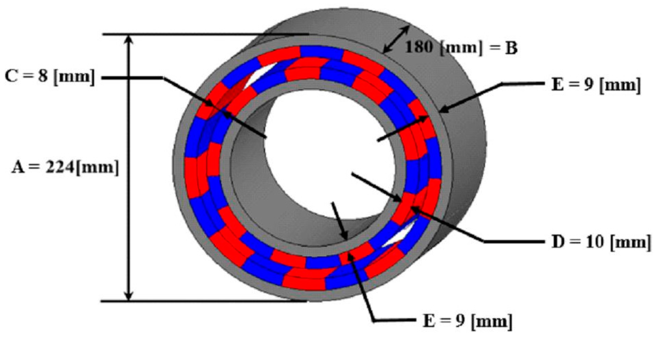
4. Design of a 10 kW Magnetic Coupling

As stated earlier, the project aims to combine three separately developed technologies/components and combine these to manufacture a 10 kW marine current turbine. It is hypothesized that the combination of the three components will allow the deployment of the system to areas with lower current speeds and also increase the efficiency of the turbine in tidal sites of economic interest.
This section will describe the design considerations for the Magnetic Coupler for the 10 kW marine current turbine. These will namely the magnets, bulkhead and the outer rotor. There have been several investigations that were conducted for the design of the 10 kW model. Only the magnet design, finite element analysis of the coupling design and vertical displacement will be covered here.
The magnet design is considered first. These are important to ensure that the design will be able to transmit the torque and synchronization required. These factors are the allowable torque, dimensions and the number of poles needed.

5. Methodology of the Numerical Analysis on the 10 kW Magnetic Coupling

The numerical analysis presented in the following sections was conducted using MAXWELL and Structural Analysis software available on ANSYS.
The first analysis used MAXWELL to optimize the design of the magnets in the coupling and also obtain the maximum torque that the coupling will withstand. Figure 14a shows the outer diameter, length, and the air gap of the magnet.
The second numerical analysis is a finite element analysis on the structure of the coupling. The weight of the blade and hub are taken into consideration to see if the structure of the hub will be adversely affected.

5.1. Methodology of the Numerical Analysis of the 10 kW Design using MAXWELL

Figure 14a shows the outer diameter, length, and the air gap of the magnet. In Figure 14b, the tetra mesh of the magnet is shown. The mesh has a total of 844,362 nodes and is refined near air gap. The mesh in the air gap also made up of 8 layers of 1 mm thickness each. This design was tested using MAXWELL and the result is reported in the results section.

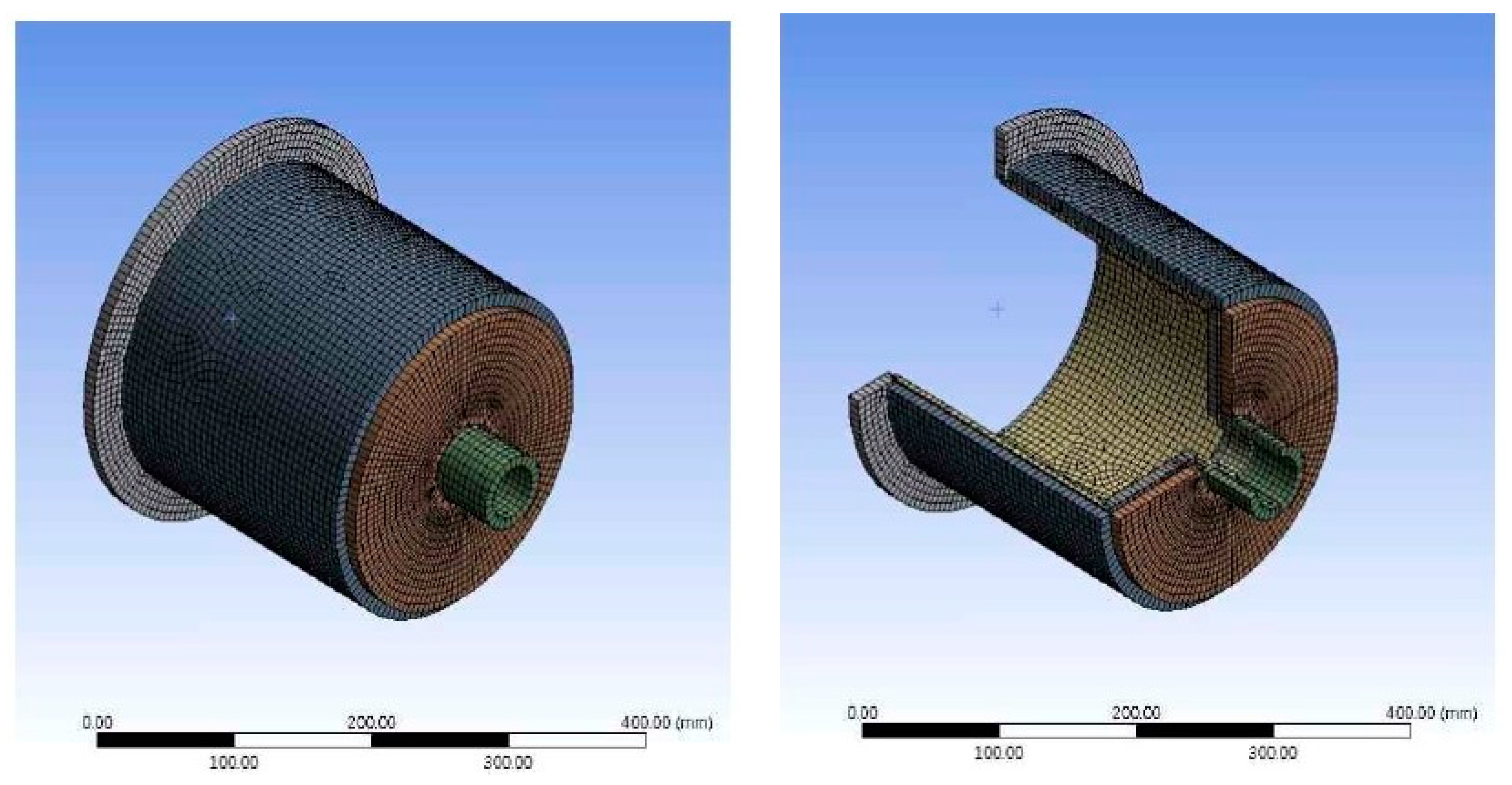
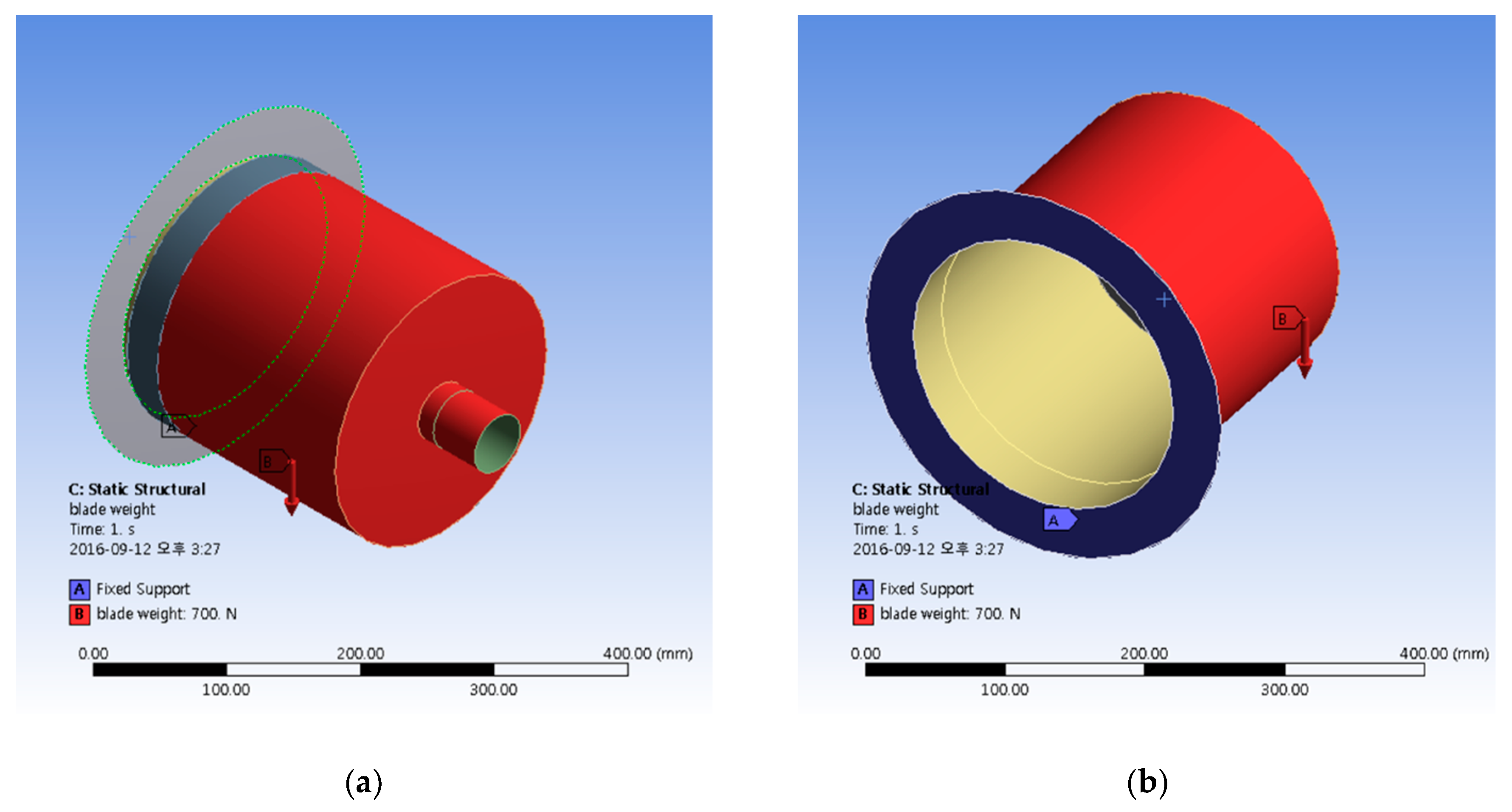
5.2. Finite Element Analysis of the 10 kW Coupler Design Methodology

The material strength of the magnetic coupler is investigated by using finite element analysis. The magnetic coupler consists of two parts; the bulkhead and the outer-rotor. In order to ensure the magnetic coupler design is safe from material failure during operation, the strength of the bulkhead wall was investigated. The bulkhead and outer-rotor are modeled as a surface body in the modeling software, Unigraphics (UG NX), as shown in Figure 15. These models are exported to ANSYS for finite element analysis. These surfaces reduce the complexity of the mesh needed for analysis of the wall strength, significantly saving time.
To analyze the wall strength, the wall thickness is varied from 3–5 mm at 0.5 mm intervals for a total of 5 cases (3, 3.5, 4, 4.5, and 5 mm). The mesh of the model for Finite element analysis of magnet couple is shown in Figure 16. Elements were created at the surface body and the physical properties of magnet coupler are specified. These are summarized in Table 3 and Table 4.
The bulkhead base will be attached to the generator nacelle, therefore the degrees of freedom is set to 0. The surface between the bulkhead and the outer rotor, shown in Figure 17, is set as a contact condition. The weight of the turbine blade and hub, as shown in Table 5, are the external forces that act on the magnetic coupling. These are applied on the region specified as the contact surface.
In addition to the analysis by varying the wall thickness, this analysis was conducted in order to study the effect of the weight of blade/hub assembly on the strength of magnet coupler. The weight of blade/hub assembly was varied into 5 cases; 700 N, 900 N, 1100 N, 1300 N, and 1500 N.
Finally, an additional analysis was done to ensure that the vertical displacement caused by the load would not cause interference between the bulkhead and outer rotor. The magnetic coupler design has a 2 mm gap in between the bulkhead and the outer rotor. The purpose of the gap is to reduce frictional losses that would occur if the two parts were in contact. The result of the vertical displacement analysis is presented in the following section.

6. Results and Discussion on the Numerical Analysis of the 10 kW Magnetic Coupling

6.1. Results of the Numerical Analysis of the 10 kW Design Using MAXWELL

In Figure 18, the results of the initial magnet design showed leakage of the magnetic field occurring between the north (N) and south (S) poles. A non-magnetized region between the N and S poles will be considered to optimize the design.
Furthermore, the torque produced at different load angles of the design was found using finite element analysis. This value is used to determine if the magnetic coupling will decouple during operation. Initially the 2D analysis was conducted and the maximum 2D torque was found to be 1381 Nm. The 2D torque values are regarded as initial values for the following 3D analysis. The 3D analysis was then conducted and the maximum torque was found to be 1190 Nm. The results are shown in Figure 19. The design value of the coupler was 1000 Nm and the 3D torque value is within an acceptable safety factor of 1.2. This indicates that in operation, the magnetic coupler will not decouple.

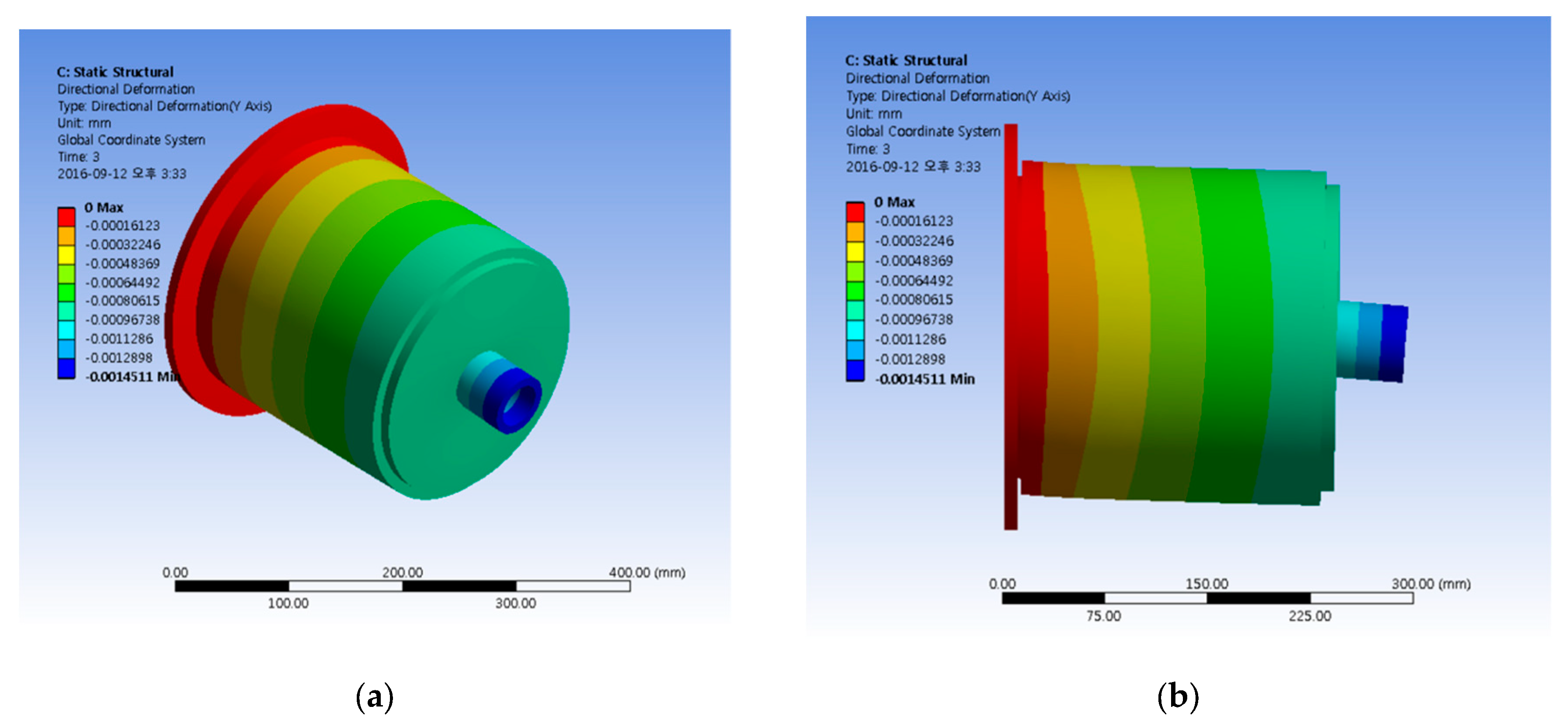
6.2. Results of the Finite Element Analysis of the 10 kW Coupling

The results of the analysis by wall thickness and weight are shown in Figure 20 and Figure 21. Figure 20 shows the amount stress plotted over the different wall thickness when the weight of the blades and hub are applied. The stress on the magnet coupler varies according to the bulkhead wall thickness and blade/hub weight. As the thickness of the wall increases, the maximum stress decreases. The maximum stress (2.713 MPa) occurs when the wall is 3 mm wall thick and a blade/hub weight of 1500 N. When compared with the yield strength of the material, 240 MPa, the results show that the material will not fail under the weight of the blades and hub. The result shows that a sufficient safety factor was achieved even though the wall thickness of the bulkhead is 3 mm.
Figure 21 shows the stress contours on the magnet coupler for a single case. It was noted that the highest stress occurs near the connection from the bulkhead to nacelle.
The result of the analysis of the vertical displacement caused by the load of the hub and blades is shown in Figure 22.
The graph shows that the vertical displacement of the magnet coupler also depends on bulkhead wall thickness and blade/hub weight. As the wall thickness increases, the maximum stress on the bulkhead decreases. For a bulkhead wall thickness of 3 mm and blade/hub weight 1500 N, the vertical displacement was 2.29 × 10⁻³ mm. Considering that the gap between the bulkhead and the outer rotor is 2 mm, it can be concluded that there is no inter-component interference due to deflection from weight of the blades and hub.
Figure 23 shows the deflection contours on the magnet coupler. The figure shows that maximum displacement occurs at the end of the hub connection.

6.3. Summary of Results on the Analysis of the 10 kW Coupling Design

As a result of the analysis conducted on the 10 kW Magnetic Coupling, Table 6 summarizes the final selected design parameters for the 10 kW Model and the dimensions are labeled in Figure 24. It is planned that a prototype will be built and tested in real seas for future studies.

7. Conclusions

This paper presented the design of a magnetic coupling for a marine current turbine. The paper presented small scale experiments and CFD analysis on a 40 W model then additional analysis on the 10 kW design.
Four different configurations of the magnetic coupling were initially tested and the Type A configuration was selected. The magnetic coupling design was compared to the mechanical oil seal design in a previous study of the counter-rotating marine current turbine. In addition, the two experimental results were compared with the results of a CFD analysis of the turbine.
The magnetic coupling setup showed an increase of about 5% power output of 122.84 ± 4.84 W compared to 116.07 ± 4.21 W from the previous study. The magnetic coupling design also had reduction of about 17% in mechanical losses. The magnetic design had power coefficient of 0.46 ± 0.06 compared to 0.45 ± 0.06 obtained by the oil seal assembly. Furthermore, the magnetic coupling case was also in close agreement with the CFD results and had a more gradual decrease in the coefficient of power (Cp) values as the velocity increased.
This paper then presented four numerical analysis conducted on the 10 kW magnetic design:
  • The first analysis used MAXWELL that determined that a magnetic leak occurred across adjacent magnets. A non-magnetic region will added to optimize the design.
  • The second analysis was a 3D finite element analysis also showed that the design over varying load angles had maximum torque of about 1190 Nm. This value is within the safety factor and is expected that the magnetic coupler will not decouple during operation.
  • The third analysis tested the strength of the material by varying the bulkhead wall thickness and weight of the blades and hub. The maximum stress of 2.713 MPa occurs when the wall is 3 mm wall thick and a blade/hub weight of 1500 N. When compared with the yield strength of the material, 240 MPa, the material is expected to withstand the load.
  • The final analysis presented showed that the maximum deflection of 2.29 × 10⁻³ mm will not interfere in the 2 mm gap between the bulkhead and outer rotor.
The magnetic coupling fulfilled the project’s requirement of watertight design for the hub. The design also had the advantage of lower torque losses and this design can be applied to other marine current designs, whether single or dual rotor.
The findings will be applied to design and manufacture a 10 kW prototype that is expected to be tested in real seas in the future.

Author Contributions

Conceptualization, Y.-H.L., I.-c.K., and J.S.Y.; methodology, I.-c.K. and J.-S.Y.; software, I.-c.K. and J.-S.Y.; formal analysis, I.-c.K. and J.-S.Y.; data curation, J.W. and I.-c.K.; writing—original draft preparation, J.W., W.T., and I.-c.K.; writing—review and editing, J.W. and I.-c.K.; supervision, I.-c.K. and Y.-H.L.; project administration, I.-c.K., J.-S.Y., and Y.-H.L. All authors have read and agreed to the published version of the manuscript.

Funding

This research was funded by the Korea Institute of Energy Technology Evaluation and Planning (KETEP) and the Ministry of Trade, Industry & Energy (MOTIE) of the Republic of Korea. (Project No. 20163030071850).

Conflicts of Interest

The authors declare no conflict of interest.

References

  1. Ministry of Trade, Industry and Energy, Third Energy Master Plan: A New Energy Paradigm for the Future. South Korea. Available online: https://www.etrans.or.kr/ebook/05/files/assets/common/downloads/Third%20Energy%20Master%20Plan.pdf (accessed on 17 August 2020).
  2. Park, E. Potentiality of Renewable resources: Economic feasibility perspectives in South Korea. Renew. Sustain. Energy. Rev. 2017, 79, 61–70. [Google Scholar] [CrossRef]
  3. Kim, G.; Lee, M.; Lee, K.; Park, J.; Jeong, W.; Kang, S.; Soh, J.; Kim, H. An overview of ocean renewable energy resources in Korea. Renew. Sustain. Energy. Rev. 2012, 16, 2278–2288. [Google Scholar] [CrossRef]
  4. Byun, D.; Hart, D.; Jeong, W. Tidal Current Energy Resources off the South and West Coasts of Korea: Preliminary Observation-Derived Estimates. Energies 2013, 6, 566–578. [Google Scholar] [CrossRef]
  5. Hwang, S.; Jo, C. Tidal Current Energy Resource Distribution in Korea. Energies 2019, 12, 4380. [Google Scholar] [CrossRef] [Green Version]
  6. Ko, D.; Chung, J.; Lee, K.; Park, J.; Yi, J. Current Policy and Technology for Tidal Current Energy in Korea. Energies 2019, 12, 1807. [Google Scholar] [CrossRef] [Green Version]
  7. Rourke, F.; Boyle, F.; Reynolds, A. Marine current energy devices: Current status and possible future applications in Ireland. Renew. Sustain. Energy. Rev. 2010, 14, 1026–1036. [Google Scholar] [CrossRef] [Green Version]
  8. Zhou, Z.; Benbouzid, M.; Charpentier, J.; Scuiller, F.; Tang, T. Development in large marine current turbine technologies—A review. Renew. Sustain. Energy. Rev. 2017, 71, 852–858. [Google Scholar] [CrossRef]
  9. Glauert, H. Airplane propellers. In Aerodynamic Theory; Springer: Berlin/Heidelberg, Germany, 1935; Volume IV, pp. 169–360. [Google Scholar]
  10. Newman, B. Actuator-Disc Theory for Vertical-Axis Wind Turbines. J. Wind Eng. Ind. Aerodyn. 1983, 15, 347–355. [Google Scholar] [CrossRef]
  11. Newman, B. Multiple Actuator-Disc Theory for Wind Turbines. J. Wind Eng. Ind. Aerodyn. 1986, 24, 215–225. [Google Scholar] [CrossRef]
  12. Clarke, J.; Connor, G.; Grant, A.; Johnstone, C. Design and testing of a contra-rotating tidal current turbine. Proc. Inst. Mech. Eng. Part A J. Pow. Energy 2007, 221, 171–179. [Google Scholar] [CrossRef] [Green Version]
  13. Clarke, J.; Connor, G.; Grant, A.; Johnstone, C.; Ordonez-Sanchez, S. Contra-rotating marine current turbines: Single point tethered floating system-stability and performance. In Proceedings of the 8th European Wave and Tidal Energy Conference, Uppsala, Sweden, 7–10 September 2009. [Google Scholar]
  14. Huang, B.; Kanemoto, T. Performance and Internal Flow of a Counter-rotating Type Tidal Stream Turbine. J. Therm. Sci. 2015, 24, 410–416. [Google Scholar] [CrossRef]
  15. Wei, X.; Huang, B.; Liu, P.; Kanemoto, T. Performance Research of Counter-rotating Tidal Stream Power Unit. Int. J. Fluid Mach. Syst. 2016, 9, 129–136. [Google Scholar] [CrossRef] [Green Version]
  16. Lee, N.; Kim, I.; Kim, C.; Hyun, B.; Lee, Y. Performance study on a counter-rotating tidal current turbine by CFD and model experimentation. Renew. Energy 2015, 79, 122–126. [Google Scholar] [CrossRef]
  17. Yoon, S.; Choo, H.; Kim, H.; Hwang, G. Design of Magnetic Coupling for Underwater Mooring Tidal Current Generator’s Shaft Sealing. In Proceedings of Annual Fall Meeting of the Korean Society for New & Renewable Energy; Korean Society for New & Renewable Energy: Jeju City, Korea, 2015; p. 118. [Google Scholar]
  18. Chen, T.; Liou, L. Blockage corrections in wind tunnel tests of small horizontal axis wind turbines. J. Exp. Therm. Fluid Sci. 2011, 35, 565–569. [Google Scholar] [CrossRef]
  19. International Organization for Standardization (ISO). Guide to the Expression of Uncertainty in Measurement; ISO: Vernier, Geneva, 1995. [Google Scholar]
  20. Kim, I.; Lee, N.; Wata, J.; Hyun, B.; Lee, Y. Experiments on the magnetic coupling in a small scale counter rotating marine current turbine. In Proceedings of the 7th International Conference on Pumps and Fans (ICPF2015), Hangzhou, China, 18–21 October 2015. [Google Scholar]
  21. Coleman, H.; Steele, W. Experimentation, Validation, and Uncertainty Analysis for Engineers, 3rd ed.; John Wiley & Sons: Hoboken, NJ, USA, 2009. [Google Scholar]
Figure 1. Small Scale model of the counter-rotating marine current turbine.
Energies 13 05725 g001
Figure 2. Two-dimensional (2D) view of the parts in the magnetic coupling.
Energies 13 05725 g002
Figure 3. Three-dimensional (3D) models of Type A and Type B arrangement of magnets.
Energies 13 05725 g003
Figure 4. (a) Previous Turbine’s mechanical oil seal coupling; (b) assembly of magnetic coupling; (c) a SolidWorks rendering of magnetic coupling.
Energies 13 05725 g004
Figure 5. The Tetra mesh of all the configurations tested in MAXWELL are presented here: (a) mesh of Type A, (b) Type B, (c) Type C, and (d) Type D.
Energies 13 05725 g005
Figure 6. The Type A magnetic coupling configuration is tested for maximum torque.
Energies 13 05725 g006
Figure 7. Front and side view of the turbine, measurement equipment, and water tank.
Energies 13 05725 g007
Figure 8. Air tightness test results over 30 min. A change of 0.3 × 10⁻³ bar is within limits.
Energies 13 05725 g008
Figure 9. MAXWELL results show the calculated torque at different magnet alignment angles for all configurations.
Energies 13 05725 g009
Figure 10. Comparing MAXWELL and Experiment results for Type A configuration.
Energies 13 05725 g010
Figure 11. Oil seal and magnetic coupling torque mechanical loss.
Energies 13 05725 g011
Figure 12. The power output against water velocity. Comparison between the oil seal, magnetic coupling experimental results and Computational Fluid Dynamics (CFD) results.
Energies 13 05725 g012
Figure 13. The Coefficient of Power (Cp) for 3 cases are compared.
Energies 13 05725 g013
Figure 14. The 10 kW-magnetic coupling design (a) shows the outer diameter and length of the magnetic coupler; (b) shows the mesh of the coupler and air gap. The air gap is made of eight layers of 1 mm thickness.
Energies 13 05725 g014
Figure 15. Magnet coupler three-dimensional (3D) models of the bulkhead and outer rotor. (a) Side view of the bulkhead and outer rotor together, (b) an isometric view of the bulkhead and outer rotor, (c) the exploded view of bulkhead and outer rotor.
Energies 13 05725 g015
Figure 16. Finite element modeling and mesh of magnet coupler.
Energies 13 05725 g016
Figure 17. The boundary condition is set for the bulkhead and outer rotor. (a) The red surface is where the contact condition is applied. (b) The blue region shows where the fixed support condition is specified.
Energies 13 05725 g017
Figure 18. Leakage of magnetic field.
Energies 13 05725 g018
Figure 19. Torque (2D and 3D) versus angular position of rotor.
Energies 13 05725 g019
Figure 20. Shows the variation of stress on the magnet coupler versus bulkhead wall thickness and blade/hub assembly weight.
Energies 13 05725 g020
Figure 21. Stress contour on the magnet coupler. In this case, the bulkhead wall thickness is 4 mm and the blade/hub assembly weight 1100 N. (a) The isometric view of the stress contours. (b) The side elevation of the model also the highest stress region occurs near the base of the bulkhead.
Energies 13 05725 g021
Figure 22. Shows the variation of vertical displacement on the magnet coupler versus bulkhead wall thickness and blade/hub assembly weight.
Energies 13 05725 g022
Figure 23. Deflection contours on the magnet coupler for the case where the bulkhead thickness is 4 mm and the blade and hub weight of 1100 N. (a) The isometric view of the model. (b) The side elevation of the magnetic coupler shows the largest displacement occurring at the end of the hub connection.
Energies 13 05725 g023
Figure 24. Final Design parameters of the 10 kW Magnet coupler. The dimensions from Table 6 are labeled here.
Energies 13 05725 g024
Table 1. Neodymium (NdFeB) magnet properties.
PropertyValue
Recoil Permeability1.05
Curie Temp. (°C)310–350
Maximum Working Temperature (°C)80–230
Reversible Temperature Coefficient Of Induction (Br) (%/°C)−0.13 to −0.09
Reversible Temperature Coefficient Of Coercivity (Hej) (%/°C)−0.70 to −0.45
Density (kg/m3)7400–7600
Vickers Hardness (Hv)560–600
Elasticity Modulus (kN/mm2)140–170
Flexural Strength (N/mm2)120–400
Compressive Strength (N/mm2)850–1050
Coefficient of Thermal Expansion Perpendicular to Magnetization Direction (10−6/°C)−2 to 0
Coefficient of Thermal Expansion Parallel to Magnetization Direction (10−6/°C)4–9
Specific Electric Resistance (106Ω.m)1.3–1.6
Specific Heat Capacity (J/(kg °C))350–500
Thermal Conductivity (W/(m °C))5–15
Table 2. Summary of the Magnetic Coupling Configurations.
Type AType BType CType D
Magnets are attached end-to-end, 3 mm gapMagnets are Separated, 3 mm gapType A 4 mm gapType A design 3 mm gap Back Yoke removed
The inner and outer rotor consists of 8 separate magnets each
The magnets are made of grade 50 M sintered NdFeB
Outer Diameter: 80 mm Length: 56 mm
Back Yoke is made of S45 C steel
Table 3. Number of Nodes and Elements for the Bulkhead and Outer Rotor.
Part NameBodyNodesElements
BulkheadSurface Body70326959
Outer RotorSurface Body64416378
TOTAL13,47313,337
Table 4. Physical properties of the magnetic coupler (bulk head and outer rotor).
TypeElastic Modulus (Pa)Poisson’s RatioDensity (kg/m3)
Steel (STS304)2.00 × 10110.267850
Table 5. The weight of blade(s) and hub specified on the contact surface.
Part NameWeight (kg)Weight (N)
Blade (1ea)22.6222
Blades (3ea)67.8666
Hub44.3434
TOTAL112.11100
Table 6. Final design parameters of 10 kW magnetic coupling.
Part LabelParametersSpecifications
A.Outer Diameter [mm]224
B.Lamination Length, [mm]180
C.Air Gap [mm]8
D.Permanent Magnet Thickness [mm]10
E.Back Yoke Thickness, E [mm]9
Number of Pole18
Type of Permanent MagnetNdFeB with a remanent field of 1.25 tesla (T)
Publisher’s Note: MDPI stays neutral with regard to jurisdictional claims in published maps and institutional affiliations.

