Article

Lithium-Ion Battery SoC Equilibrium: An Artificial Potential Field-Based Method

1
School of Automation, Central South University, Changsha 410083, China
2
School of Computer Science and Engineering, Central South University, Changsha 410083, China
*
Author to whom correspondence should be addressed.
Energies 2020, 13(21), 5691; https://doi.org/10.3390/en13215691
Submission received: 27 September 2020 / Revised: 26 October 2020 / Accepted: 27 October 2020 / Published: 30 October 2020

Abstract

:
Battery balance methods are the key technology to ensure the safe and efficient operation of the energy storage systems. Nevertheless, convenient balance methods experience slow convergence and difficult to adapt to quick charging applications. To solve the problem, in this paper, an artificial potential field-based lithium-ion battery balance method is proposed. Firstly, a cyber-physical model of the battery equalization system is proposed, in which the physical layer models the circuit components and the cyber layer represents the communication topology between the batteries. Then the virtual force function is established by artificial potential field to attract the voltage and state-of-charge of each cell to nominal values. With a feedback control law, the charging current of the battery is reasonably distributed to realize the rapid balance among batteries. The experimental results verify the effectiveness and superiority of the proposed method.

1. Introduction

Lithium-ion batteries have been widely used in electric vehicles [1,2,3], trains [4,5,6] and hybrid energy storage systems [7,8,9] owing to their advantages such as large capacity, lightweight, high safety, and small size [10,11]. In practice, it is generally necessary to connect multiple batteries in series to meet the high voltage demand [12]. Due to the manufacturing tolerances, batteries usually have a voltage imbalance when connected. Over-voltage and under-voltage may occur in some batteries during charging and discharging, which will seriously affect the health of the batteries and the safety of the system [13]. If overvoltage occurs, CO 2 , C 2 H 4 , and other gases will cause the temperature and pressure inside the battery to rise, resulting in serious battery damage or explosion. If under-voltage occurs, the internal reaction will result in a large loss of battery capacity. Therefore, it is necessary to balance the batteries to eliminate the imbalance between the batteries and avoid overvoltage and under-voltage.
At present, the equalization circuits of energy storage systems are usually classified into dissipative circuits and non-dissipative circuits [14,15,16]. Dissipative circuits consume excess energy through a passive element (such as a resistor), while non-dissipative circuits store the excess energy in an active element (such as capacitance or inductance) [17]. When using non-dissipative circuits for equalization, if the voltage of the lithium-ion battery is too high, the active component will absorb the excess energy and then store it or charge the battery with lower voltage. While non-dissipative circuits have high energy efficiency, but the circuits are generally complex, large in size, and difficult to control. In contrast, although the efficiency of the non-dissipative circuit is relatively low, the circuit is simple and easy to control, so it is widely used in low-power scenarios with limited system size and expenditure budget [18].
Non-dissipative balancing circuits mainly use passive components such as resistors to consume too much energy of the battery. Switching resistance circuits can effectively compromise the energy efficiency and cost. Thus, it is widely adopted in non-dissipative balancing circuits. The switching resistance circuit controls the charging current through adjusting the duty ratio, to prevent the battery from overcharging [19]. However, the differences among batteries still affect voltage balance. Recently, researchers have proposed some strategies to optimize the effect of balance. Generally, the battery voltages are used to judge whether the battery needs to be balanced after charging and discharging. Although this method is relatively simple, it has poor performance and is vulnerable to the influence of the environment, which provides uncertainty of parameters and affects the balance effect [20]. S o C -based strategies take the charged capacity of each cell as the balance criterion, which is not easily affected by the working environment. In addition, the charging and discharging performance can be improved [21]. To obtain the S o C of each battery cell, some algorithms have been proposed [22,23].
Quite a lot of research uses S o C -based strategies to improve balance performance. For instance, a balanced method based on the screening process [24] is proposed, in which the open-circuit voltage (OCV)- S o C relationship is matched by capacity screening and resistance screening to achieve voltage/ S o C balance. A discrete quasi-sliding mode observer is designed based on saturation equalization current constraint [25] so that the converter could work together effectively and realize S o C equalization. The above methods achieve the balance mainly by controlling the battery S o C , which is relatively complex and difficult to synthesis [18,26,27].
To solve the above-mentioned challenges, we propose an asynchronous battery balance method based on an artificial potential field. The theory of artificial potential field was first proposed [28] and applied in a multi-agent obstacle avoidance scene, and then widely used in formation control among multi-agent systems. The artificial potential field-based method has a simple structure, practicality and strong real-time performance, which can reduce the complexity of controller synthesis and improve the convergence speed.
In this paper, a cyber-physical System framework of the battery equalization system is constructed, in which the physical layer models the components in the circuit, and the cyber layer corresponds to the communication topology between the batteries. Then a distributed balance controller is designed, and the artificial potential field is introduced to establish the mapping between charging S o C deviation and charging current. By controlling the charging current, the control method can accelerate the convergence of S o C and has the good scalability. Compared with existed studies, this proposed method has the following contributions:
(1)
A real-time battery balancing strategy based on the artificial potential field is proposed, and the mapping between charging S o C deviation and the desired charging current is established through the virtual force generated by the artificial potential field.
(2)
A feedback control law is designed to ensure the charging currents of batteries track the desired current, which ensures the S o C s of batteries can be balanced.
(3)
Extensive experiments have been conducted to verify the effectiveness and advantages of the proposed method.

2. Model of Battery Equilibrium System

This section introduces the physical layer model of the system. The physical model consists of the first-order resistance-capacitance (RC) dynamic circuit model of lithium-ion batteries and the circuit model of the switching resistance circuit, respectively. Then the cyber model of the whole battery equalization system is presented. The proposed cell balance method for the switching resistor circuit diagram is shown in Figure 1.

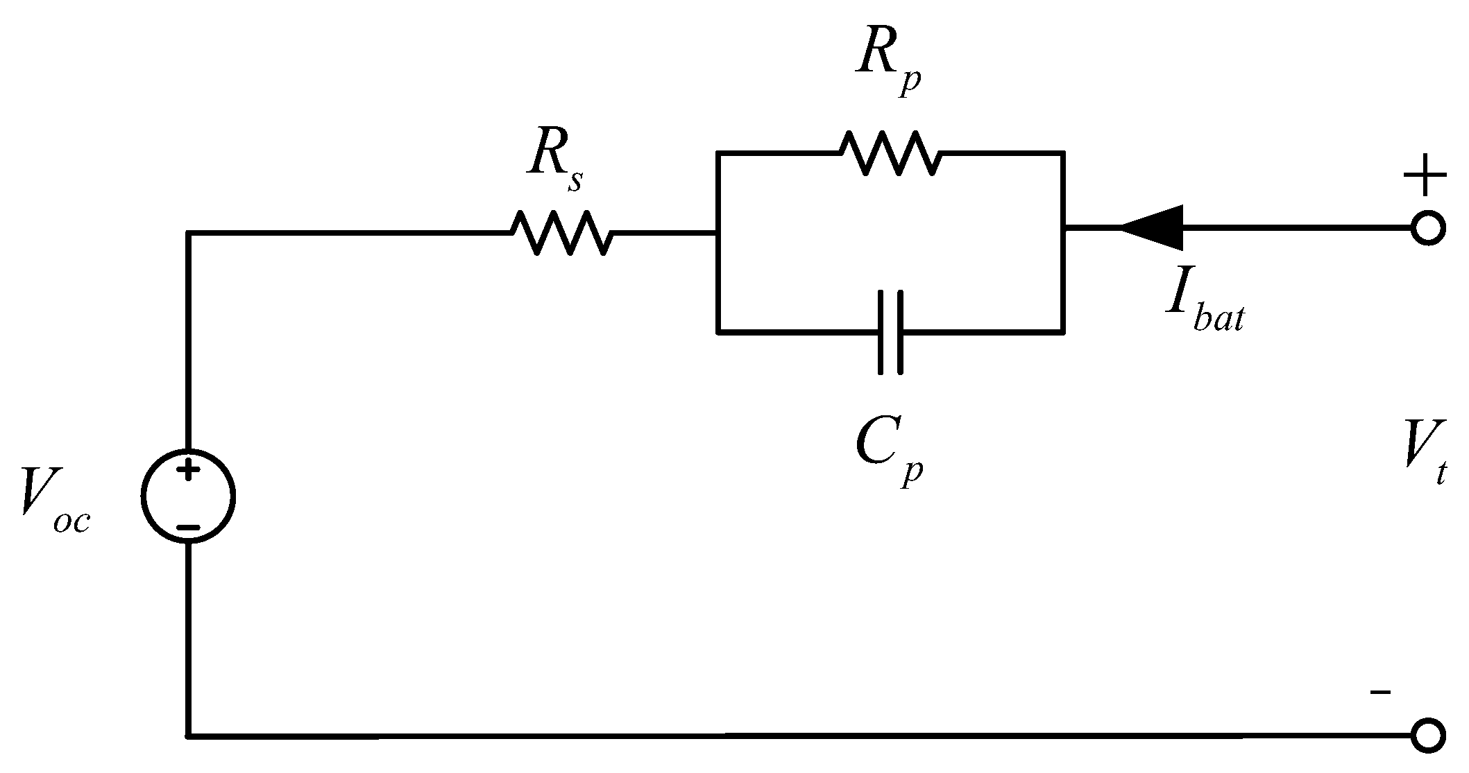
2.1. Model of Battery Cell

The first-order equivalent circuit model [29] of lithium-ion batteries is adopted considering the compromise of accuracy and complexity, as shown in Figure 2, where R s denotes the equivalent internal series resistance, R p and C p represent the polarization resistance and polarization capacitor respectively and characterize the dynamic characteristics of batteries. V t is the terminal voltage which can be measured, while V o c is the open circuit voltage of batteries. I b a t represents the charging/discharging current.
According to the circuit model, the system dynamic equations incorporating terminal voltage V t , polarization voltage V p , and the open circuit voltage V o c are given as:
V t = V o c + V p + R s I b a t ,
V p ˙ = V p R p C p + I b a t C p .
Battery S o C is taken as one of the system states in this work. According to the Ah measurement method, it satisfies
S o C t = S o C t 0 + 0 t I b a t τ C n d τ .
Namely, there is
S o C ˙ t = I b a t C n .
where C n is the nominal capacity of battery cell.
In the above equations, open circuit voltage V o c is a function of S o C , i.e., V o c = f ( S o C ) . Assuming S o C and V o c is one-to-one matching, the states are interchangeable [12]. Similar V o c S o C relation can also be found in [30]. Then Equation (4) can be written as
V o c ˙ S o C = I b a t C n .
Based on the above analysis, the state-space model of battery cell with the state vector [ S o C , V p ] is described by
S o C ˙ V p ˙ = 0 0 0 1 R p C p S o C V p + 1 C n 1 C p I b a t , V t = 1 1 V o c ( S o C ) V p + R s I b a t .
.
In this work, state vector [ S o C , V p ] are obtained by particle filtering [30].

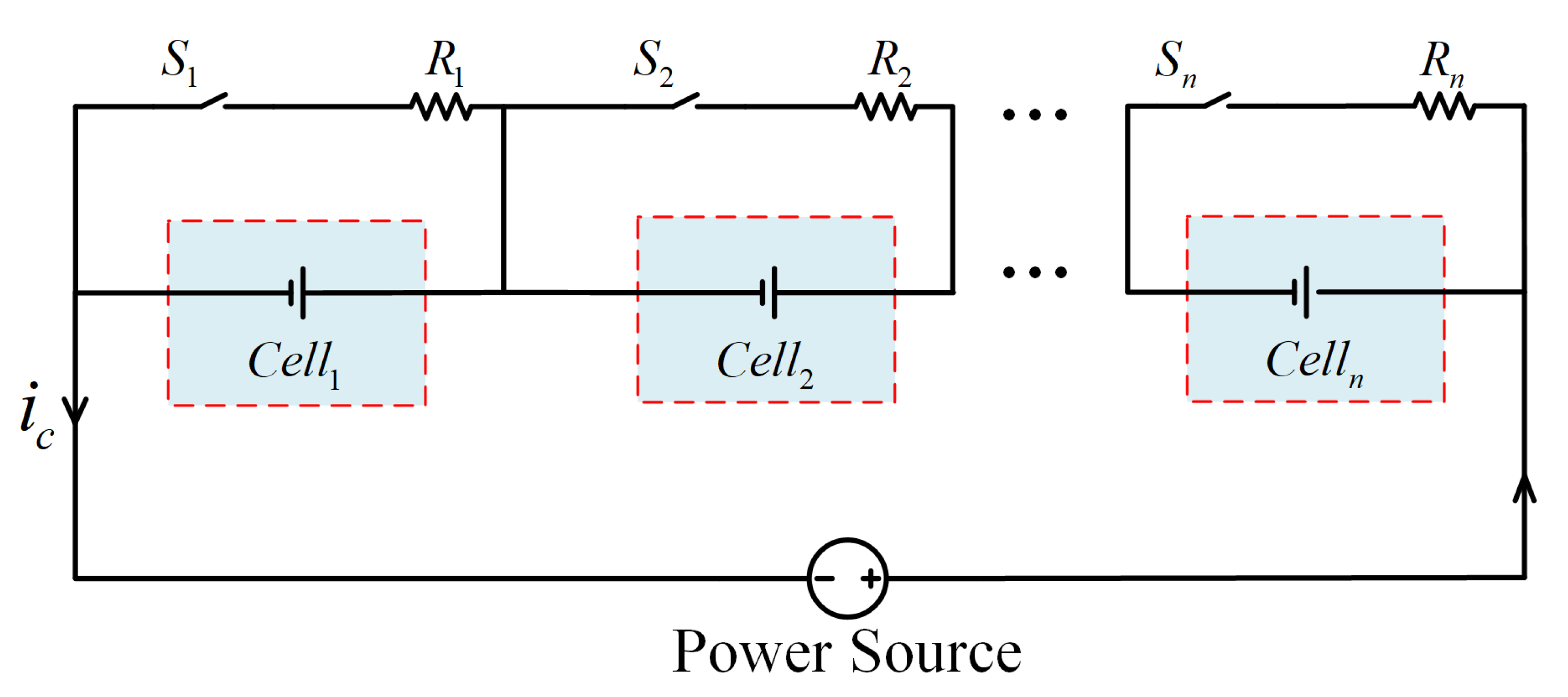
2.2. Model of Balancing Circuit

As shown in Figure 3, each cell in the physical system is connected in parallel to the balanced resistor R by a switch S. According to the circuit model in Figure 3, it can get:
I b a t = I c I s s ,
I s = V t R .
In (7), s = [ 0 , 1 ] is the duty cycle of the corresponding switch. Combining (1), (2), (5), (7), and (8), it can be written:
V p ˙ = V p R p C p I c C p + V t C p R s .
S o C ˙ = I c C n + V t C n R s .
Thus, the new state equation is:
S o C ˙ V ˙ p = 0 0 0 1 R p C p S o C V p + 1 C n 1 C p I c V t R s V t = 1 1 V o c ( S o C ) V p R R R s S + R R s R R s S I c ,
where S o C ˙ represents the increase rate of the S o C battery during the charging process. When the switch is off, S = 0 , the charging rate of the battery cell is the highest. When the switch is on, S = 1 , the charging rate of the battery cell decreases with the S o C . Here, the reference S o C of each battery cell is set as 0.9.
According to the first-order RC battery model in Figure 2, the discrete-time zero-state response and discrete-time zero-input response of the state variable V p can be approximately expressed as: R p 1 e Δ t R p C p and e Δ t R P C P V p k , respectively, where Δ t is the sampling interval and k is the sampling step. Then, the discrete form of (Section 2.2) is:
S o C k + 1 V p k + 1 = 1 0 0 e Δ t R p S o C C p S o C S o C k V p k + Δ t C n 1 C p I c k V t k R s V t k = 1 1 S o C k V p k R R R s S + R R s R R s S I c k ,
where R p and C p are functions of S o C . Thus, the system x k state can be defined as:
x k = S o C k V p k T .

2.3. Model of Cyber Layer

The interaction among cells can be represented by a directed graph, where the node set denotes the battery cells in the physical layer, and the edge set denotes the communication link between cells. Edge directions represent the flow of information between cells. If there is a directed link from cell m to cell k, then cell k can receive information from cell m and node m can be taken as one neighbor of node k. The set of all neighbors of node k is denoted by N k , and the number of neighbors of node k is denoted by D k , also known as the in-degree of node k. The degree matrix is a diagonal matrix and is defined as D = diag d k n . If there is a link between node m and node k, let a k m = 1 , otherwise a k m = 0 . The adjacency matrix of a k m is defined as A = a k m n × n . Then the Laplace matrix of the graph can be defined as L = D A .

3. Distributed Balance Strategy Based on Artificial Potential Field

In this section, a distributed balance strategy based on artificial potential field is proposed. Firstly, the artificial potential field is established to describe the S o C deviation between adjacent batteries, which generate the virtual attraction force. Then the mapping relation between virtual force and the switch duty cycle is established to adjust the charging current of each battery, which makes the S o C of all batteries equal finally.

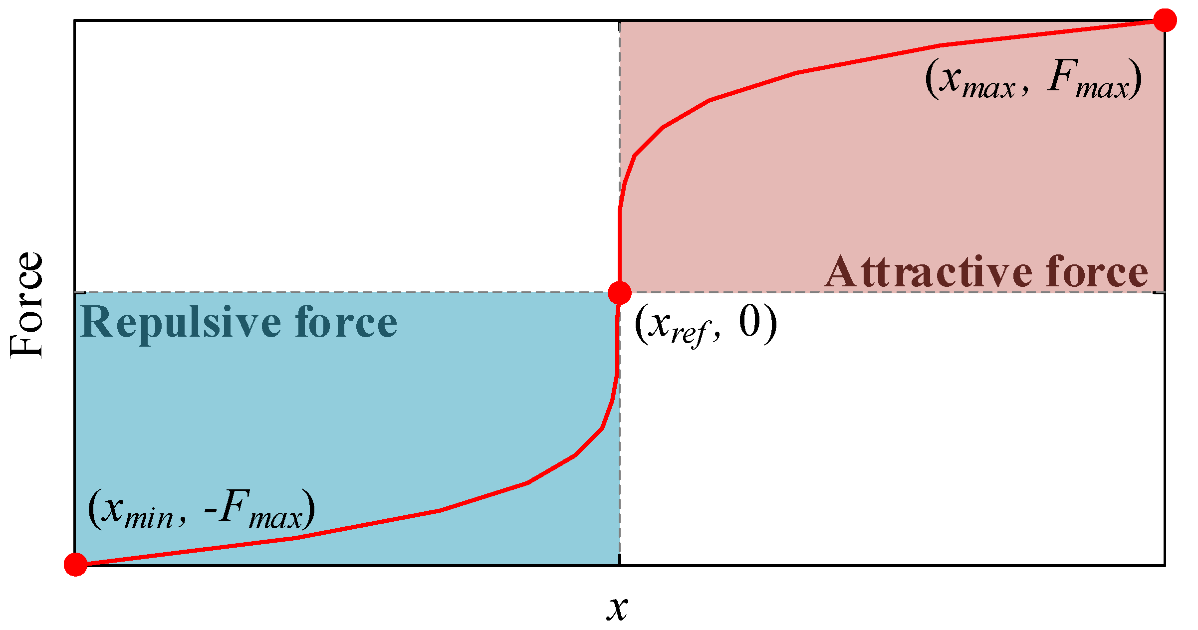
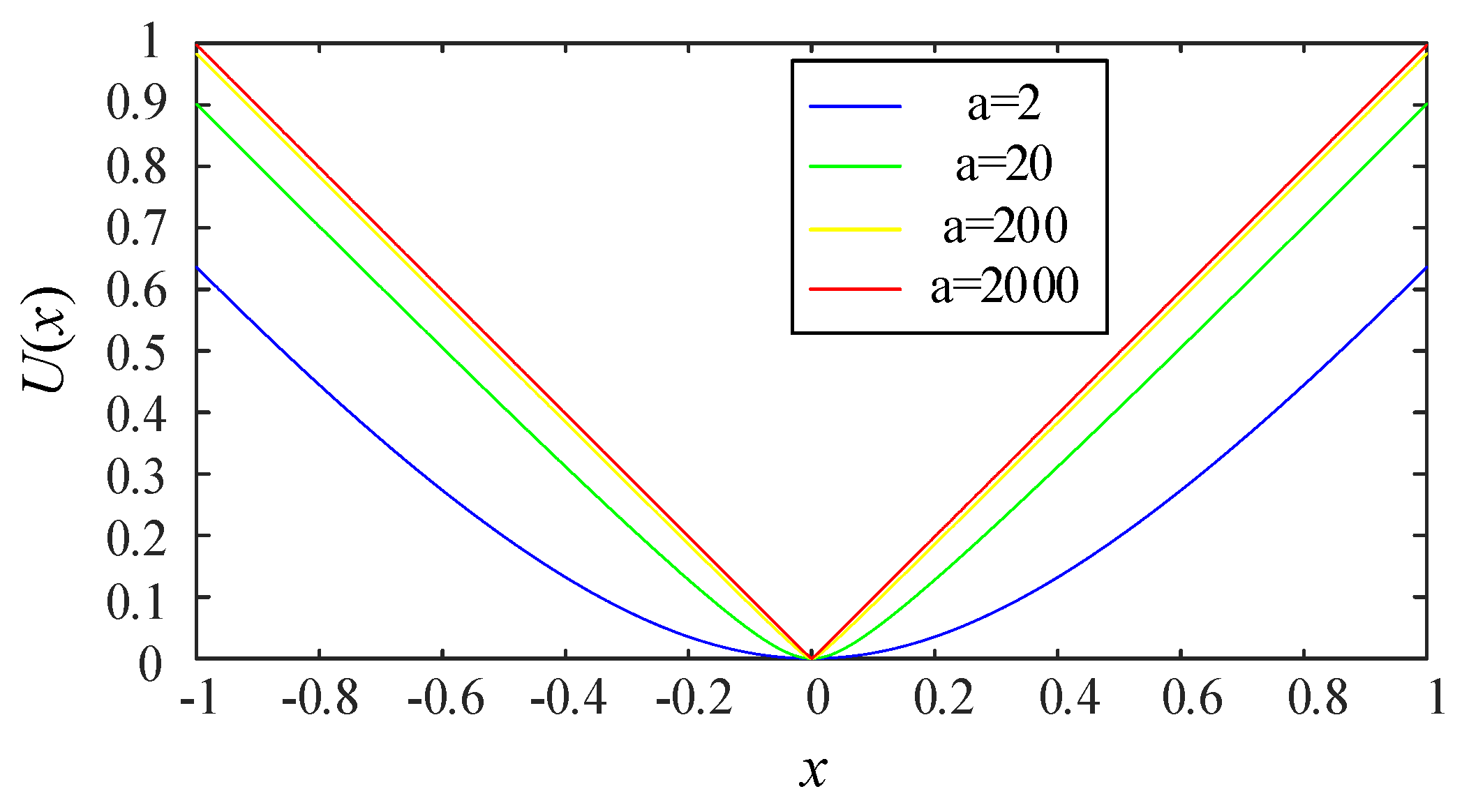
3.1. Artificial Potential Field

Artificial potential field was introduced to hybrid energy storage systems to allocate load power in real time [7]. Figure 4 shows the action function in the artificial potential field, i.e., the force function between any two agents. When the distance between any two agents is equal to the reference value, the force between them is zero, i.e., the potential energy is zero. However, when two agents are close to each other, there is a strong repulsion between them. When they are far away from each other, there is a great attraction between them. This large repulsive force, i.e., high potential energy, ensures that the distance between them can converge quickly to the given reference value. Based on the artificial potential field theory, this section proposes a real-time S o C balancing strategy to adaptively determine the charging current.

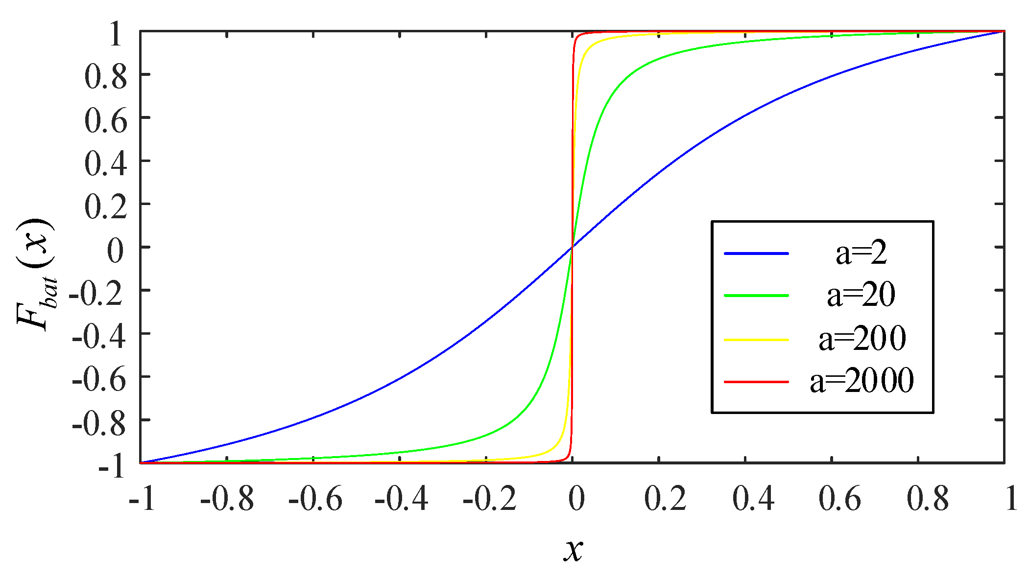
3.2. Construction of Artificial Potential Field

The objective of the equilibrium system is to make the S o C of all lithium-ion batteries uniform, that is, Δ S o C = 0 . By exerting the virtual force of artificial potential field to attract the S o C among battery cells, the proposed method can achieve S o C consistency. In this paper, to simplify the analysis, a case with 3 cells is investigated, which can be generalized to more cells conveniently. For example, When Δ S o C between the cell 1 and the cell 2 is greater than zero, that is, Δ S o C 0 , the virtual force of the artificial potential field makes the S o C s of cell 1 and the cell 2 close to a certain median value simultaneously. Cell 2 and cell 3 work in the same way. Finally, all battery cells can achieve synchronization and reach an agreement on the S o C of all battery cells. By constructing the artificial potential field, the relationship between virtual force and charging current is established. The virtual distance for each cell is defined by the S o C deviation with adjacent cell:
x = a i j S o C j S o C i ( i , j = 1 , 2 , , m ) .
Then the virtual force to attract the S o C can be defined by the virtual distance as follows, which is improved from our previous work [31] to acquire a more general form:
F b a t = arctan ( α x ) arctan ( α ) .
In (15), the range of x is [−1, 1], and the range of F b a t is [−1, 1]. The virtual force with four α values, i.e., 2, 20, 200 and 2000, are shown in Figure 5. It is worth noting that under this virtual force, when x 0 , the force F bat 0 . Thus, a positive force is generated to pull the cell with low S o C , accelerating its S o C increase. In addition, a negative force is generated to push the cell with high S o C , which makes its S o C rise slowly or even remain unchanged.
For better understanding, the virtual potential energy function can be given by the artificial potential field theory as:
U ( x ) = 0 x F b a t x d x .
As shown in Figure 6, when x = 0 , namely Δ S o C = 0 , the zero potential energy point is reached, neither positive force nor negative force is generated, which means S o C s of two battery cells are consistent. When x 0 , namely Δ S o C 0 , there is a none-zero potential energy for the two cells, pushing the S o C s of the cells to continue converging. Obviously, case α = 2000 provides a quite larger potential energy when x 0 then the others. In addition, case α = 2 has a wide low potential energy range, which may cause slow convergence of S o C consistency. It is worth noticing that U ( x ) is not used in the proposed algorithm.

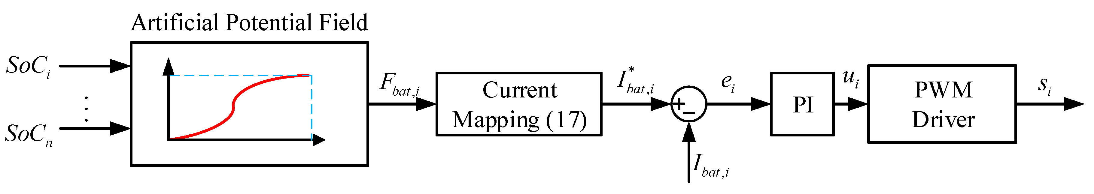
3.3. Measurement of Charge Current

In the practical battery charging process, the appropriate charging current should be determined according to the virtual force to eliminate the S o C inconsistency between different cells.
By normalizing F b a t to 0 , I max , the mapping relationship between the charging current of each cell and the virtual force F b a t can be obtained as follows:
I b a t * = I max 2 F b a t + 1 = I max ( arctan ( α x ) + arctan ( α ) ) 2 arctan ( α ) ,
where I max is the maximum acceptable current, the current range I b a t is 0 , I max , and F b a t denotes the virtual force, coming from Equation (15).
In charging mode, when x = 1 or 1 , there must be a low S o C cell charging with the maximum safe current I max , and a high S o C cell not being charged. When x = 0 , the adjacent battery cells are charged with the current I max / 2 until they are fully charged.

3.4. The Distributed Control Strategy Incorporating Artificial Potential Field

From the above discussion, we can find that the S o balance of batteries is achieved through the artificial potential field, i.e., if the current of each battery can track and follow the desired current I b a t , i * , the S o C balance among batteries is achieved. In the following, we will design a feedback control law to steer the charging current I b a t , i to the desired value. To do that, we define a tracking error as
e i = I b a t , i * I b a t , i
where e i is the tracking error, I b a t , i * is the desired current from Equation (17), I b a t , i is the measured battery current, which is used to estimate the battery S o C as well.
The current tracking error (18) further goes to a proportional-integral (PI) compensator to generate the control law u i
u i = K p ( e i + 1 T i 0 t e i d t ) ,
where K p is the proportional coefficient, and T i is the integral constant. Then the control law u i is used to drive the PWM module to generate duty cycle, i.e., signal s i in Figure 1.
The proposed distributed control strategy based on artificial potential field is depicted in Figure 7, where the reference charging current I b a t , i * comes from the S o C error between the battery and its neighbors. It is worth noticing that when α = 0 , F b a t = 0 , there is no synergistic effect for the charging process.

4. Experiment and Analysis

In this section, the effectiveness of the proposed battery charging and balancing strategy is evaluated through experimental results. Firstly the parameter setting and hardware configuration of the charging system are introduced, and then experiments are conducted to compare the performance of the proposed method with the classical method.

4.1. Parameter Setting

The selected battery type is ICR18650 with rated voltage of 3.7 V and capacity of 2200 mAh. The initial S o C s of the three batteries are different, that is, S o C 1 0 = 0 . 6 , S o C 2 0 = 0 . 55 and S o C 3 0 = 0 . 5 respectively. The target charging S o C of each battery is set to 0.9. The switching resistance is 1 Ω in the experiment.

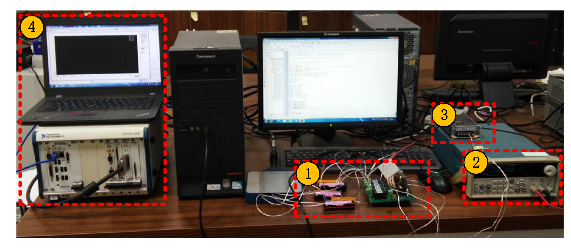
4.2. Experiment Platform

The hardware components of the battery equilibrium charging system are shown in Figure 8. The experiment platform mainly consists of four parts: (1) control board, three batteries, three yellow switching resistors; (2) DC 24 V power supply; (3) Constant-current constant-voltage power supply; (4) PXI device.
The main function of the control board is to control the charging current by operating the switch. The control board consists of a voltage measurement module, control module, communication module, and CAN module. Since measurement accuracy is very important, three high-precision voltage sampling sensors are selected to measure the terminal voltage of each battery. The control algorithm calculates S o C , based on the measured data, which are deployed on-chip TMS3202808.
The PXI device measures the voltage of the three batteries through a measuring board and displays the voltage curve in the host computer using Ni-Veristand. PXI is a robust PC-based system for measurement and automation with high-performance low-cost deployment. There are two power supplies in the experiment platform. CC power supply can provide charging current for the battery in the system.

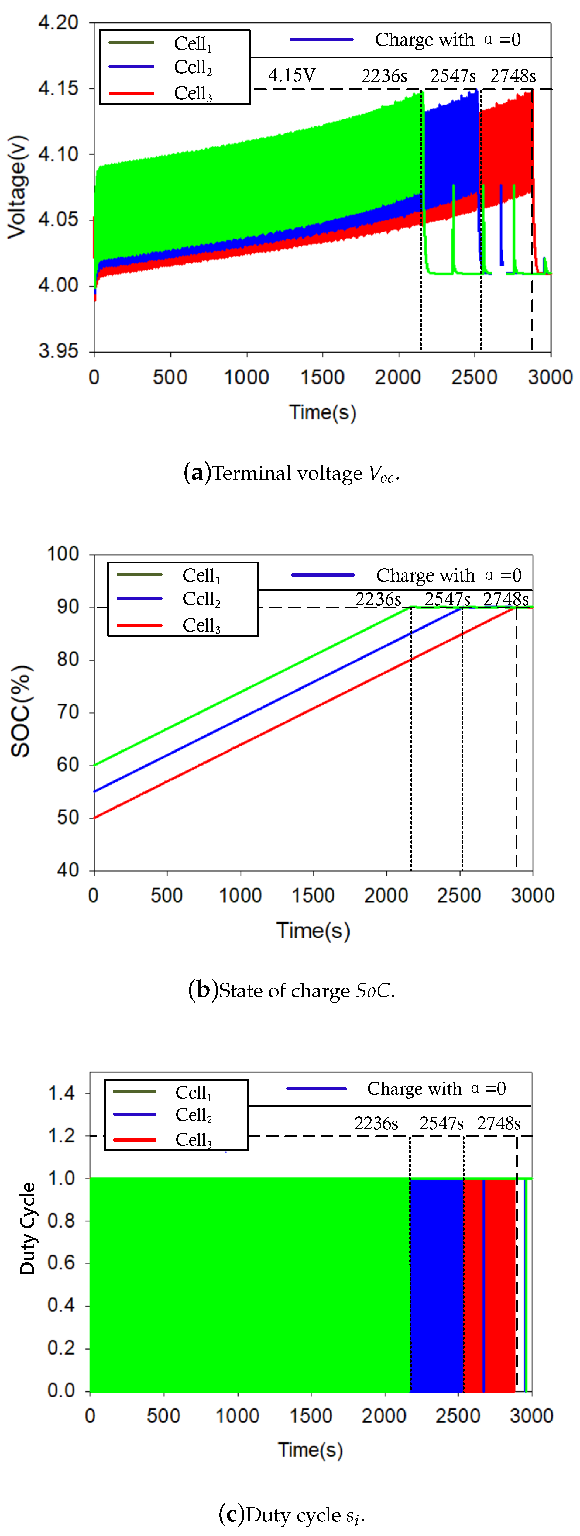
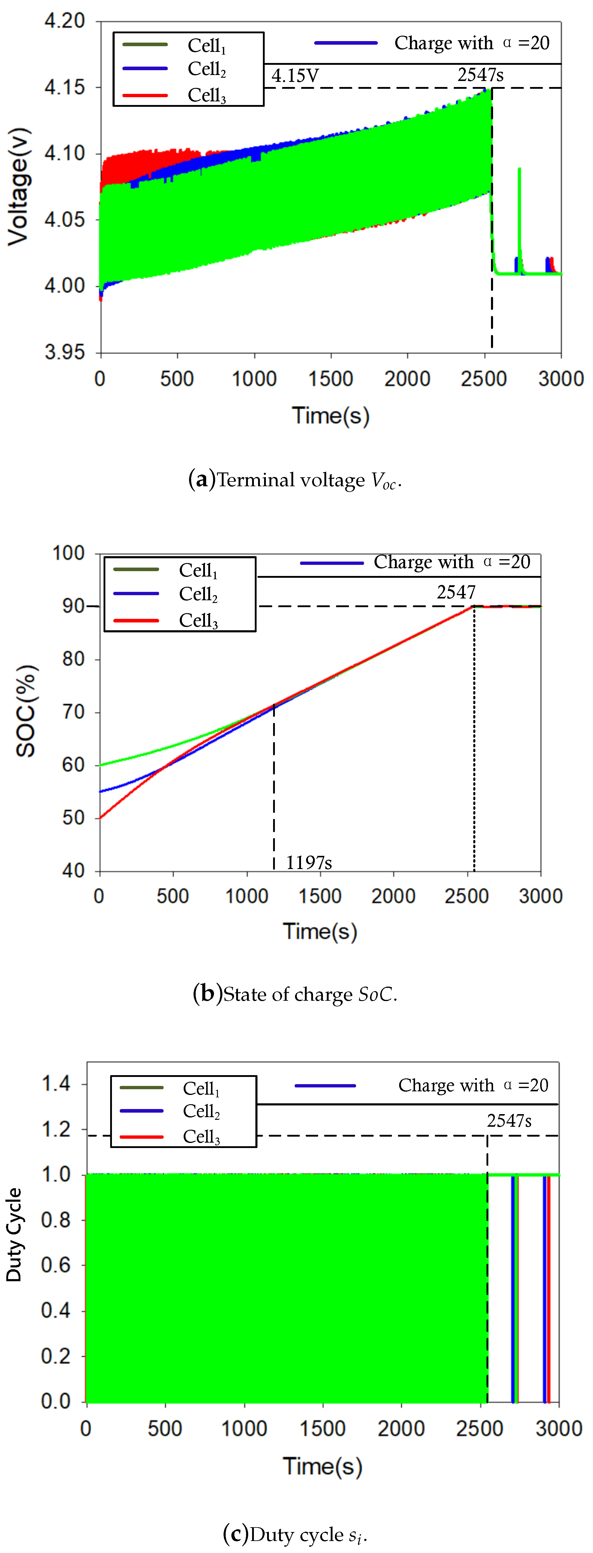
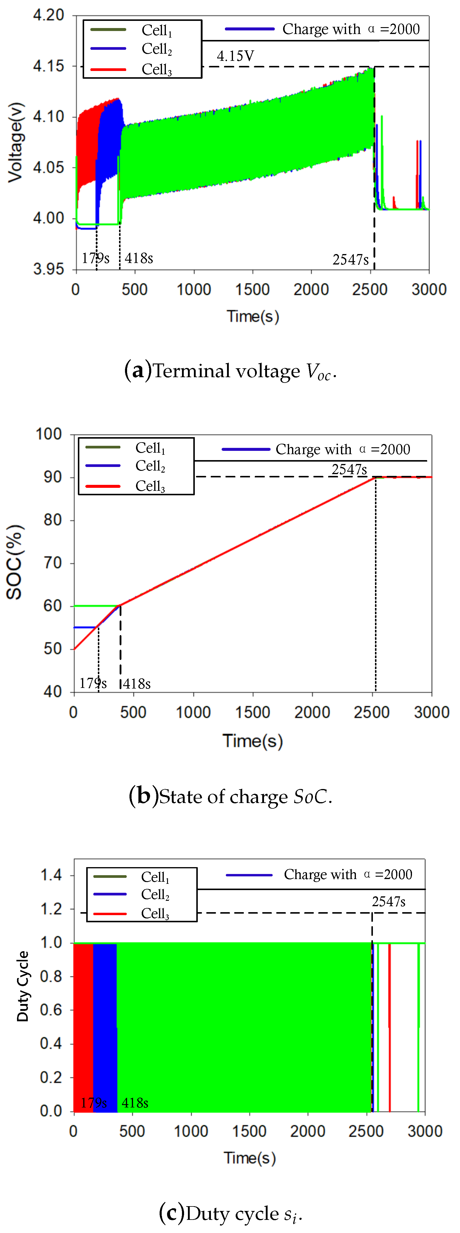
4.3. Experiment Results

Experiments are conducted to compare the proposed strategy based on artificial potential field with different parameters ( α = 20 and α = 2000 , respectively) and the conventional strategy without artificial potential field ( α = 0 ) [26]. Case α = 200 is not presented since α = 200 and α = 2000 have similar effects in Figure 5. The control performance of battery terminal voltage V o c , state-of-charge S o C and duty cycle S k are carried out of these three cases. Figure 9 presents the results with no artificial potential field control method, while Figure 10 and Figure 11 contain the results under artificial potential field with α = 20 and 2000 respectively.
From Figure 9a, it can be seen that the three batteries start charging with I max / 2 , i.e., 0.5 C at the same time. When the terminal voltage reaches the upper bound of 4.15 V, charging is stopped. The charging times of the three batteries are 2236 s, 2547 s and 2748 s respectively. As shown in Figure 9b, the S o C s of three cells rise at the same rate. When the upper bound 0.9 is reached, three cells are balanced. Figure 9c presents the drive signal of three MOSFETs. When Cell 1 is fully charged, the corresponding switch is turned off first, followed by the second and third switch at 2547 s and 2748 s, respectively.
The proposed artificial potential field-based method reveals completely different results in Figure 10 and Figure 11. With parameter α = 20 , it can be seen that Cell 3 with the lowest S o C has the maximal charging current, while Cell 2 and 3 have much smaller currents. The voltages of the three cells eventually achieve synchronously in the 1197 s. When the voltages reach the upper bound, they all stop charging. In Figure 10b, it can be seen that the three batteries start charging at the same time. The charging time of the three batteries is 2547 s. Before 1197 s, the charging current of Cell 3 is larger than 0.5 C, while charging currents of Cell 2 and 3 are smaller than 0.5 C. From 1197 s to 2547 s, three cells are charged with I max / 2 , i.e., 0.5 C. Since α = 20 is not large enough, and three cells share similar charging currents (around 0.5 C), there is no significant difference of the drive signals in Figure 10c. In fact, before 1197 s, the duty cycle of switch 1 is smaller than 2 and 3.
Under α = 2000 , Cell 3 with the lowest S o C starts to charge first, while there is no charge for Cell 1 and 2. This is because the steep force function with α = 2000 limits the charging current of cells with higher S o C to 0, and makes low S o C cell charge with I m a x . In Figure 11a, the voltage of Cell 3 rises rapidly, while Cell 2 and 3 start to charge at 179 s and 418 s respectively. Figure 11b demonstrates the S o C results, where Cell 3 is charged quickly before S o C convergence point t = 418 s, after 197 s Cell 2 joints the quick charging process. After three cells achieve S o C equilibrium at 418 s, they start to charge with I max / 2 . Figure 11c illustrates that Cell 1 and 2 start to charge at 418 s and 197 s respectively. It is worth noticing that the charging time has no difference between α = 2000 and α = 20 , but the S o C convergence time of case α = 2000 is much earlier than case α = 20 .

4.4. Results Discussion

The proposed method with large parameter α provides a fast S o C convergence of batteries, however, it suffers from high energy consumption. It can be clearly observed from Figure 11b that, when approaching the balance, excess energy is dissipated on the shunt resistance. The energy consumption of the artificial potential field method under three different parameters is shown in Table 1. As can be seen from the table, when the parameter α is large, the energy consumption of the system is also high, even greater than that of the traditional control method. In practice, a concave function mapping energy consumption and parameter α can be derived. An optimal α can be obtained by solving the concave function.

5. Conclusions

This paper proposes an artificial potential field-based S o C equilibrium algorithm for battery charging system. Firstly, a cyber-physical model of the battery equalization system is proposed, in which the physical layer models the circuit components and the cyber layer represents the communication topology between the batteries. Then, S o C state error of different batteries is defined as a new virtual distance, then virtual potential force is constructed based on the virtual distance for each battery cell. The charging current is adaptively adjusted through force mapping. Experimental results demonstrate the proposed algorithm can realize the rapid balance among batteries during charging process.

Author Contributions

Conceptualization, H.L. (Hongtao Liao) and F.J.; methodology, C.J. and H.L. (Hongtao Liao); validation, C.J. and Y.W.; data curation, H.L. (Hongtao Liao). and Y.L.; writing—original draft preparation, H.L. (Heng Li) and Z.H.; writing—review and editing, H.L. (Hongtao Liao) and J.P. All authors have read and agreed to the published version of the manuscript.

Funding

This work is supported by the National Natural Science Foundation of China (Grant Nos.61672537, 61803394).

Conflicts of Interest

The authors declare no conflict of interest.

References

  1. Andwari, A.M.; Pesiridis, A.; Rajoo, S.; Martinez-Botas, R.; Esfahanian, V. A review of Battery Electric Vehicle technology and readiness levels. Renew. Sustain. Energy Rev. 2017, 78, 414–430. [Google Scholar] [CrossRef]
  2. Hu, X.; Tang, X. Review of modeling techniques for lithium-ion traction batteries in electric vehicles. J. Mech. Eng. 2017, 53, 20–31. [Google Scholar] [CrossRef]
  3. Xiong, R.; Duan, Y. Development and verification of the equilibrium strategy for batteries in electric vehicles. J. Beijing Inst. Technol. 2018, 27, 22–28. [Google Scholar]
  4. Cheng, L.; Wang, W.; Wei, S.; Lin, H.; Jia, Z. An improved energy management strategy for hybrid energy storage system in light rail vehicles. Energies 2018, 11, 423. [Google Scholar] [CrossRef] [Green Version]
  5. Herrera, V.I.; Gaztañaga, H.; Milo, A.; Saez-de Ibarra, A.; Etxeberria-Otadui, I.; Nieva, T. Optimal energy management and sizing of a battery–supercapacitor-based light rail vehicle with a multiobjective approach. IEEE Trans. Ind. Appl. 2016, 52, 3367–3377. [Google Scholar] [CrossRef]
  6. Herrera, V.; Milo, A.; Gaztañaga, H.; Etxeberria-Otadui, I.; Villarreal, I.; Camblong, H. Adaptive energy management strategy and optimal sizing applied on a battery-supercapacitor based tramway. Appl. Energy 2016, 169, 831–845. [Google Scholar] [CrossRef]
  7. Wu, Y.; Huang, Z.; Liao, H.; Chen, B.; Zhang, X.; Zhou, Y.; Liu, Y.; Li, H.; Peng, J. Adaptive power allocation using artificial potential field with compensator for hybrid energy storage systems in electric vehicles. Appl. Energy 2020, 257, 113983. [Google Scholar] [CrossRef]
  8. Ahmad, A.B.; Ooi, C.A.; Ishak, D.; Teh, J. State-of-charge balancing control for On/OFF-line internal cells using hybrid modular multi-level converter and parallel modular dual L-bridge in a grid-scale battery energy storage system. IEEE Access 2018, 7, 131–147. [Google Scholar] [CrossRef]
  9. Huang, W.; Qahouq, J.A.A. Energy sharing control scheme for state-of-charge balancing of distributed battery energy storage system. IEEE Trans. Ind. Electron. 2014, 62, 2764–2776. [Google Scholar] [CrossRef]
  10. Zhang, S. Chemomechanical modeling of lithiation-induced failure in high-volume-change electrode materials for lithium ion batteries. NPJ Comput. Mater. 2017, 3, 1–11. [Google Scholar] [CrossRef]
  11. Nitta, N.; Wu, F.; Lee, J.T.; Yushin, G. Li-ion battery materials: Present and future. Mater. Today 2015, 18, 252–264. [Google Scholar] [CrossRef]
  12. Bruen, T.; Marco, J.; Gama, M. Model based design of balancing systems for electric vehicle battery packs. IFAC-PapersOnLine 2015, 48, 395–402. [Google Scholar] [CrossRef]
  13. Isaacson, M.; Hollandsworth, R.; Giampaoli, P.; Linkowsky, F.; Salim, A.; Teofilo, V. Advanced lithium ion battery charger. In Proceedings of the Fifteenth Annual Battery Conference on Applications and Advances (Cat. No. 00TH8490), Long Beach, CA, USA, 11–14 January 2000; IEEE: New York, NY, USA, 2000; pp. 193–198. [Google Scholar]
  14. Li, L.; Huang, Z.; Li, H.; Peng, J. A rapid cell voltage balancing scheme for supercapacitor based energy storage systems for urban rail vehicles. Electr. Power Syst. Res. 2017, 142, 329–340. [Google Scholar] [CrossRef]
  15. Agrawal, B.; Adam, M.; Vadala, B.; Koke, H.; McCurlie, L.; Preindl, M.; Ahmed, R.; Emadi, A. Non-dissipative battery cell balancing using half-bridge switching circuit. In Proceedings of the 2016 IEEE Transportation Electrification Conference and Expo (ITEC), Dearborn, MI, USA, 27–29 June 2016; IEEE: New York, NY, USA, 2016; pp. 1–6. [Google Scholar]
  16. Li, H.; Peng, J.; Zhou, Y.; He, J.; Huang, Z.; He, L.; Pan, J. Soh-aware charging of supercapacitors with energy efficiency maximization. IEEE Trans. Energy Convers. 2018, 33, 1766–1775. [Google Scholar] [CrossRef]
  17. Daowd, M.; Omar, N.; Van Den Bossche, P.; Van Mierlo, J. Passive and active battery balancing comparison based on MATLAB simulation. In Proceedings of the 2011 IEEE Vehicle Power and Propulsion Conference, Chicago, IL, USA, 6–9 September 2011; IEEE: New York, NY, USA, 2011; pp. 1–7. [Google Scholar]
  18. Vitols, K. Design of an embedded battery management system with passive balancing. In Proceedings of the 2014 6th European Embedded Design in Education and Research Conference (EDERC), Milan, Italy, 11–12 September 2014; IEEE: New York, NY, USA, 2014; pp. 142–146. [Google Scholar]
  19. Linzen, D.; Buller, S.; Karden, E.; De Doncker, R.W. Analysis and evaluation of charge-balancing circuits on performance, reliability, and lifetime of supercapacitor systems. IEEE Trans. Ind. Appl. 2005, 41, 1135–1141. [Google Scholar] [CrossRef]
  20. Quinn, D.D.; Hartley, T.T. Design of novel charge balancing networks in battery packs. J. Power Sources 2013, 240, 26–32. [Google Scholar] [CrossRef]
  21. Zhong, L.; Zhang, C.; He, Y.; Chen, Z. A method for the estimation of the battery pack state of charge based on in-pack cells uniformity analysis. Appl. Energy 2014, 113, 558–564. [Google Scholar] [CrossRef]
  22. Meng, J.; Ricco, M.; Luo, G.; Swierczynski, M.; Stroe, D.I.; Stroe, A.I.; Teodorescu, R. An overview and comparison of online implementable SOC estimation methods for lithium-ion battery. IEEE Trans. Ind. Appl. 2017, 54, 1583–1591. [Google Scholar] [CrossRef]
  23. Nejad, S.; Gladwin, D.; Stone, D. A systematic review of lumped-parameter equivalent circuit models for real-time estimation of lithium-ion battery states. J. Power Sources 2016, 316, 183–196. [Google Scholar] [CrossRef] [Green Version]
  24. Kim, J.; Shin, J.; Chun, C.; Cho, B. Stable configuration of a Li-ion series battery pack based on a screening process for improved voltage/SOC balancing. IEEE Trans. Power Electron. 2011, 27, 411–424. [Google Scholar] [CrossRef]
  25. Ouyang, Q.; Chen, J.; Zheng, J.; Hong, Y. SOC estimation-based quasi-sliding mode control for cell balancing in lithium-ion battery packs. IEEE Trans. Ind. Electron. 2017, 65, 3427–3436. [Google Scholar] [CrossRef]
  26. Daowd, M.; Omar, N.; Van den Bossche, P.; Van Mierlo, J. A review of passive and active battery balancing based on Matlab/Simulink. Int. Rev. Electr. Eng. 2011, 6, 2974–2989. [Google Scholar]
  27. Aizpuru, I.; Iraola, U.; Canales, J.; Echeverria, M.; Gil, I. Passive balancing design for Li-ion battery packs based on single cell experimental tests for a CCCV charging mode. In Proceedings of the 2013 International Conference on Clean Electrical Power (ICCEP), Alghero, Italy, 11–13 June 2013; IEEE: New York, NY, USA, 2013; pp. 93–98. [Google Scholar]
  28. Khatib, O. Real-time obstacle avoidance for manipulators and mobile robots. In Proceedings of the 1985 IEEE International Conference on Robotics and Automation, St. Louis, MO, USA, 25–28 March 1985; IEEE: New York, NY, USA, 2003. [Google Scholar]
  29. Mostafa, A.; Das, M. Robust identification of time-varying electrical equivalent circuit models of Li-ion batteries. In Proceedings of the 2017 IEEE International Conference on Electro Information Technology (EIT), Lincoln, NE, USA, 14–17 May 2017; pp. 382–387. [Google Scholar]
  30. Du, J.; Wang, Y.; Wen, C. Li-ion battery SOC estimation using particle filter based on an equivalent circuit model. In Proceedings of the 2013 10th IEEE International Conference on Control and Automation (ICCA), Hangzhou, China, 12–14 June 2013; IEEE: New York, NY, USA, 2013; pp. 580–585. [Google Scholar]
  31. Jiang, F.; Jin, C.; Liao, H.; Wu, Y.; Liu, Y.; Peng, J.; Huang, Z. An artificial potential field-based lithium-ion battery soc equilibrium method in electric vehicles. IFAC-PapersOnLine 2020. to be published. [Google Scholar]
Figure 1. The proposed cell balance method for the switched resistor circuit diagram.
Energies 13 05691 g001
Figure 2. The first-order RC circuit model for batteries.
Energies 13 05691 g002
Figure 3. The balancing circuit model diagram.
Energies 13 05691 g003
Figure 4. The force function of artificial potential field diagram.
Energies 13 05691 g004
Figure 5. Diagram of virtual force F b a t x function.
Energies 13 05691 g005
Figure 6. Virtual potential energy U ( x ) S o C diagram.
Energies 13 05691 g006
Figure 7. Distributed control strategy incorporating artificial potential field for battery cell.
Energies 13 05691 g007
Figure 8. Experiment hardware setup: (1) control board, three batteries and three resistors, (2) CC-CV power source, (3) DC 24 V power source, (4) PXI platform.
Energies 13 05691 g008
Figure 9. Results without artificial potential field (conventional) control method.
Energies 13 05691 g009
Figure 10. Results of the artificial potential field method with α = 20 .
Energies 13 05691 g010
Figure 11. Results of the artificial potential field method with α = 2000 .
Energies 13 05691 g011
Table 1. Energy consumption of shunt resistor.
CaseEnergy Consumption (wh)Convergence Time (s)Charing Time (s)
Conventional method α = 0 10.1827482748
α = 20 9.7111972547
α = 2000 10.434182547
Publisher’s Note: MDPI stays neutral with regard to jurisdictional claims in published maps and institutional affiliations.

