Abstract
The application of advanced technologies for engine efficiency improvement and emissions reduction also increase the occurrence possibility of abnormal combustions such as incomplete combustion, misfire, knock or pre-ignition. Novel promising combustion modes, which are basically dominated by chemical reaction kinetics show a major difficulty in combustion control. The challenge in precise combustion control is hard to overcome by the traditional engine map-based control method because it cannot monitor the combustion state of each cycle, hence, real-time cycle-resolved in-cylinder combustion diagnosis and control are required. In the past, cylinder pressure and ion current sensors, as the two most commonly used sensors for in-cylinder combustion diagnosis and control, have enjoyed a seemingly competitive relationship, so all related researches only use one of the sensors. However, these two sensors have their own unique features. In this study, the idea is to combine the information obtained from both sensors. At first, two kinds of ion current detection system are comprehensively introduced and compared at the hardware level and signal level. The most promising variant (the DC-Power ion current detection system) is selected for the subsequent experiments. Then, the concept of ion current/cylinder pressure cooperative combustion diagnosis and control system is illustrated and implemented on the engine prototyping control unit. One application case of employing this system for homogenous charge compression ignition abnormal combustion control and its stability improvement is introduced. The results show that a combination of ion current and cylinder pressure signals can provide richer and also necessary information for combustion control. Finally, ion current and cylinder pressure signals are employed as inputs of artificial neural network (ANN) models for combustion prediction. The results show that the combustion prediction performance is better when the inputs are a combination of both signals, instead of using only one of them. This offline analysis proves the feasibility of using an ANN-based model whose inputs are a combination of ion current and pressure signals for better prediction accuracy.
1. Introduction
Recently, internal combustion (IC) engines have been facing the problem of greenhouse gas emissions and exhaust pollutants. Some proposals have even suggested a ban on the sale of vehicles with combustion engines. However, from the statistical results, IC engines provide about 25% of the world’s power, while at the same time they only produce about 10% of the world’s greenhouse gas emissions [1,2]. Obviously, IC engines have made a huge contribution to promoting the development of the world. Moreover, due to the insufficient charging piles, short battery life, the recycling of used batteries, and other issues of hybrid or electric vehicles, it is highly probable that the IC engines still have a high share in the market [3].
With the application of advanced technologies such as direct fuel injection [4,5], high compression ratio [6,7], lean-burn [8,9], exhaust gas recirculation (EGR) [10,11], advanced ignition system [12,13], waste heat recovery [14,15], water injection [16,17], or novel combustion modes such as homogenous charge compression ignition (HCCI) [18,19], partial premixed compression ignition (PPCI) [20,21], and reactivity controlled compression ignition (RCCI) [22,23], the thermal efficiency and emissions of IC engines have been improved significantly. But at the same time, advanced technologies also increase the occurrence possibility of abnormal combustions such as incomplete combustion, misfire, knock or pre-ignition, and the difficulty in combustion control especially for novel combustion modes which are basically dominated by chemical reaction kinetics. The challenges in precise combustion control are hard to overcome by the traditional engine map-based control method because it cannot monitor the combustion state in every cycle. Real-time cycle-resolved in-cylinder combustion diagnosis and control will be required for the next generation of IC engines.
The cylinder pressure sensor is the most common means of in-cylinder combustion diagnosis and control. Its typical application scenarios are summarized in Figure 1 [24]. With its high-frequency characteristics, it is able to do knock diagnosis and control. With its low-frequency characteristics, it can be used for closed-loop control of maximum brake torque timing (MBT) and air-fuel ratio (A/F). It can also be applied for misfire diagnosis and transient performance control. The following will give a brief overview of the application of cylinder pressure in these fields.
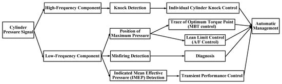
Figure 1.
The typical application scenarios of cylinder pressure signals [24].
As early as 1951, Draper et al. [25] proposed that cylinder pressure can be used as a closed-loop control signal for MBT. Subsequently, both Nissan and Honda [24,26] used the cylinder pressure peak time as a characteristic parameter to calculate the MBT compensation for each cycle. With this control strategy, the fuel consumption can be reduced by 1–3%. Zhu et al. [27] compared the performance of using cylinder pressure differential peak, cylinder pressure peak time, and 50% cumulative heat release (CA50) for MBT closed-loop control. It is found that all three parameters can control the ignition timing in the vicinity of MBT, but only the cylinder pressure differential peak does not need to be calibrated, which is more suitable for MBT closed-loop control. For the prediction of the air-fuel ratio based on cylinder pressure, Houpt et al. [28] used the combustion duration to fit the air-fuel ratio, but the limitation of this method is that it is related to the engine operating conditions, fuel, and other parameters. Tunestål et al. [29] employed the heat release rate curve to estimate the air-fuel ratio. However, none of the above methods consider the effect of residual exhaust gas coupling between cycles on the actual air-fuel ratio. Shen et al. [30] considered the transfer of residual exhaust gas between cycles. The results of using cylinder pressure to estimate the air-fuel ratio are very close to the results measured by the oxygen sensor under different operating conditions.
Another common application area of cylinder pressure is combustion diagnosis, especially for abnormal combustion. In 1979, Powell et al. [31] confirmed that the high-frequency oscillation of the cylinder pressure signal can characterize the intensity of knock. Then Sawamoto et al. [32] developed a closed-loop control strategy based on cylinder pressure signals for knock suppression. This strategy successfully expanded the engine torque by 15%. Ravaglioli et al. [33] installed one pressure sensor per cylinder on the Ferrari Formula 1 engines. Based on the combustion information calculated from cylinder pressure, the ignition and injection were adjusted to avoid pre-ignition. Cho et al. [34] improved the evaluation index of knock by reasonable filtering method for cylinder pressure. With this analysis method, it is able to realize transient knock control. Misfire diagnosis is also important as a part of the On-Board Diagnosis II (OBDII) regulation. A sustained misfire will increase the carbon deposit or even damage the three-way catalyst. Shimasaki et al. [35] proposed a misfire detection algorithm based on cylinder pressure when the calculated IMEP is below the predetermined threshold. Similarly, Cesario et al. [36] utilized cylinder pressure for the detection of misfire and partial burning. The misfire fault recognition probability is over 95% at different speeds and loads.
Apart from the cylinder pressure sensor, research on the application of ion current sensor in combustion control has gradually increased in recent years. The basic principle of its formation is that hydrocarbon fuel will generate ions and electrons during the combustion process. When an external electric field is applied to the ion current sensor, the ions and electrons will move directionally to form an ion current. For gasoline engines, the spark plug can be used directly as an ion current sensor, so the cost is much lower than the cylinder pressure sensor. Given its potential in industrial mass production applications, it has been extensively studied in recent years.
Gürbüz [37] studied the correlation between the ion current signal and cylinder pressure in a spark-ignition (SI) engine. A significant positive relationship between periods of combustion, ion current signals, and the local gas temperature was observed. When the engine is running under EGR conditions, the ion current signal is weakened due to the decrease in combustion temperature, but the correlation between the ion current signal and the combustion parameters is still as high as 0.9 [38]. On the natural gas engines and diesel engines, it is also found that the correlation between ion current signal and combustion parameters is higher than 0.9 [39,40]. In addition, on the HCCI engine, the experimental results of Johansson et al. [41] show that the correlation coefficient of the ion current characteristic parameter and CA50 is 0.877, so the ion current signal can be used to estimate the combustion phase of HCCI. Similar results are also reflected in [42,43]. Therefore, under various conditions, the ion current signal has been proved to be highly correlated with combustion parameters, which is the basis for the prediction, diagnosis, and control of combustion.
Hellring et al. [44] took the ion current signal as input and used a neural network model to estimate the CA50 and peak cylinder pressure, which was used for closed-loop control of ignition timing. In addition, similar to the cylinder pressure signal, the ion current signal can also predict the air-fuel ratio, but the difference is that the ion current signal predicts the local air-fuel ratio, that is, the air-fuel ratio near the spark plug. This feature has a special significance for engines that adopt a fuel stratification strategy because the fuel concentration near the spark plug needs to be strictly controlled [45].
Ion current signal can also be used for abnormal combustion diagnosis and control. Auzins et al. [46] tested the success rate of misfire diagnosis in the cases of fuel cutoff and ignition cutoff. Under different operation conditions, the success rate of misfire diagnosis based on ion current signals can be 100%. In our research group, lots of researches have been conducted related to ion current based misfire diagnosis and control [47,48,49]. Using the amplitude or integral value of ion current signals as the criterion, the misfire can be diagnosed in the current cycle. The methods of re-ignition and re-injection are applied for misfire control. For knock diagnosis and control, Collings et al. [50] compared the experimental results of knock diagnosis with ion current and cylinder pressure and confirmed the feasibility of ion current in knock detection. Laganá et al. [51] studied the characteristics of the ion current signal and knock sensor signal under no-knock, weak knock, and strong knock conditions. When knock occurs, the ion current signal begins to oscillate, and the higher the knocking intensity, the stronger the oscillation. By extracting the frequency domain information of the ion current signal, the correlation coefficient with the knock sensor signal is 0.74. The pre-ignition is a major problem faced by downsizing engines in recent years. Due to the early occurrence of pre-ignition, sufficient time is provided for pressure propagation, which is more destructive to the engine than an ordinary knock. In 2015, for the first time, Tong et al. [52] detected the pre-ignition on a turbocharged gasoline direct injection engine using the ion current signal. Then, in 2019, Wang et al. [53] used ion current signals to detect pre-ignition and used additional fuel injection cooling method to successfully suppress super knock which is induced by pre-ignition under current combustion cycle.
Overall, both the cylinder pressure and the ion current signal can be applied for combustion diagnosis and control. In the past, the two sensors are more like a competing relationship, hence, all related researches only use one of the sensors. However, these two sensors have their own unique features. The cylinder pressure sensor is a “physical sensor” which provides global pressure in the cylinder, while the ion current sensor is a “chemical sensor” that provides localized information around the spark plug. Therefore, in this study, the idea is to combine the information obtained from both sensors to get richer information for combustion diagnosis and control.
At first, two kinds of ion current detection systems are comprehensively introduced and compared. One of them is selected for the subsequent experiments. Then the ion current/cylinder pressure cooperative combustion diagnosis and control system is illustrated and implemented. One application case of using this system for HCCI abnormal combustion control and stability improvement is introduced. Finally, the potential of ion current/cylinder pressure synergy combined with an artificial neural network (ANN) model for combustion prediction has been evaluated.
2. Comparison of Ion Current Detection Systems
Due to the weak ion current signal (microampere level) and the complex electrical environment of the engine, to obtain a high-quality ion current signal requires careful design of the entire system and a large number of experiments for design iteration. In addition, although the basic principle of the circuit is simple, due to the different electronic components and signal processing methods used in each laboratory, the measured ion current signal differs in the waveform, amplitude, and signal-to-noise ratio. In this study, two ion current detection systems are introduced and compared from the hardware level and signal level in both SI and HCCI modes.
One is called direct current power (DC-Power) ion current detection system. Its basic circuit is shown in Figure 2a. On the basis of retaining the original ignition circuit, an ion current detection circuit is connected in parallel. The high voltage power supply module provides DC voltage for the ion current circuit. The capacitor connected in parallel with the high voltage module plays the role of voltage stabilization and energy storage, and its capacitance determines the speed of voltage attenuation. The high voltage silicon stack is used to isolate the instantaneous high voltage generated during ignition so that the electronic components will not be damaged. Another system named the capacitive ion current detection system is shown in Figure 2b. When ignition happens, the discharge current charges the capacitor and is used as the voltage supply to drive the ion current. Since the ion current loop is in series with the ignition loop, various diodes such as transient suppression diodes, fast recovery diodes, Schottky diodes are employed in this circuit to suppress the damage of discharge surge to electronic components. Due to the lack of high voltage modules to continuously charge the capacitor, it is necessary to consider the attenuation of the capacitor voltage. For the engine test, the capacitor is charged once after each cycle of ignition, so the capacitor only needs to ensure sufficient voltage in one cycle. Through calculation, the capacitor charging energy in the circuit is only 0.5 mJ, which is not enough to affect normal ignition process. Besides, the energy consumption of the capacitor in each cycle is only 10% when the data acquisition is completed. Therefore, the voltage decay process of the capacitor can be ignored. The original ion current signal obtained from two detection systems is processed with the same signal processing method including signal differential and resistor-capacitance filtering.
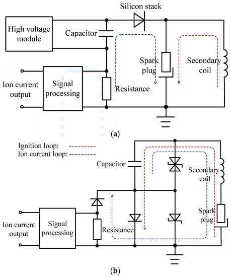
Figure 2.
Schematic of two ion current detection systems: (a) DC-Power type; (b) Capacitive type.
At the hardware level, the advantage of DC-Power ion current detection system is the adjustable output voltage from high voltage power supply. Since the ion current signal is quite sensitive to operating conditions such as air-fuel ratio or intake pressure, its amplitude should be maintained at a level that can be used for combustion analysis. The flexible out voltage can easily meet this requirement. However, the disadvantage is that it is not compatible with mainstream ignition systems, because the DC-Power ion current detection system requires the direction of the ignition current to flow from the center electrode of the spark plug to the side electrode, but the increasingly popular ignition system usually connects the center electrode of the spark plug as “negative electrode”, while the side electrode and the whole cylinder are “positive electrode”, causing the direction of the ignition current to change from the side electrode to the center electrode. The purpose of this design is mainly to improve the ignition stability, because the temperature of the center electrode is higher than that of the side electrode, and it is easier to emit electrons. Therefore, in order to be able to adopt a DC-Power ion current detection system in the test, the ignition coil of the engine was replaced from the original pen ignition coil (the direction of the ignition current flows from the side electrode to the center electrode) to a relatively traditional static split ignition coil (the direction of the ignition current flows from the center electrode to the side electrode).
For the capacitive ion current detection system, its advantages and disadvantages at the hardware level are just the opposite of DC-Power ion current detection systems. Once the withstand voltage of the capacitor is determined, its output voltage is also fixed. Hence, to change the amplitude of the ion current signal can only be achieved by adjusting the resistance. However, it is found that the amplitude of the ion current signal is not linearly related to the resistance. When the resistance increases to a certain extent such as 5 MΩ, the duration of the ion current signal will also be elongated, causing the signal to deform and fail to truly reflect the combustion process. On the other hand, the capacitive ion current detection system can perfectly adapt to the mainstream ignition systems since the ignition current direction of this system flows from the side electrode to the center electrode as shown in Figure 2b.
In addition to the differences in hardware, there are also differences in the ion current signals measured by the two detection systems. Figure 3 shows the typical ion current signals measured by two ion current detection systems in SI and HCCI modes. In the SI mode, the ion current signal measured by the DC-power ion current detection system has four peaks as shown in Figure 3a, which are an energy storage peak, a discharge peak, a chemical ionization peak, and a thermal ionization peak. Among them, the energy storage peak and the discharge peak are two interference peaks generated on the ion current detection circuit at the moment when the ignition coil starts to store energy and the ignition discharge occurs. When the discharge is over, it begins to enter the main part of the ion current signal. In the early stage of combustion, chemical reactions take place on the flame front, generating a large number of charged particles such as H3O+ and electrons. Under the effect of high voltage, a directional movement is generated to form a chemical ionization peak. In the burned area, part of the combustion products will be ionized at high temperatures to generate charged particles such as NO+ and electrons. This part of the charged particles forms a thermal ionization peak in the middle and late stages of the entire combustion process. Its peak position is very close to the peak position of the cylinder pressure.

Figure 3.
Typical ion current signals measured by two ion current detection systems in SI (1500 r/min, IMEP = 0.28 MPa, Ignition timing = −22 °CA aTDC (after Top Dead Center)) and HCCI modes (1500 r/min, IMEP = 0.3 MPa): (a) DC-Power type in SI mode; (b) Capacitive type in SI mode; (c) DC-Power type in HCCI mode; (d) Capacitive type in HCCI mode.
From Figure 3b, energy storage interference and discharge interference also can be observed in the ion current signal measured by the capacitive ion current detection system, but the main part of the ion current has only thermal ionization peaks. Through analysis, the oscillation duration of the discharge interference of this circuit is too long. Because chemical ionization occurs in the early stage of combustion, it is submerged in the discharge peak. This leads to a loss of combustion information at the early stage, which is one of the drawbacks of capacitive ion current detection systems.
In HCCI mode, Figure 3c shows the ion current signal measured by the DC-power ion current detection system. During the negative valve overlap period and the main combustion period, the ion current signal corresponds quite well to the cylinder pressure signal. Since in HCCI mode, ignition is no longer needed, there is no energy storage or discharge interferences. However, for the capacitive ion current detection system, the capacitor in the circuit needs ignition to charge for ensuring normal operation. In order to avoid affecting the combustion process, it can only be ignited once in the exhaust stroke, so it can be seen from Figure 3d that the energy storage and discharge interferences appear at this time. The additional ignition not only causes losses to the ignition system but also affects the ion current signal during NVO. From the red dotted circle in Figure 3d, due to the slower speed of the discharge peak falling to zero, the starting time of the ion current signal during NVO is affected. Moreover, instead of starting from zero, a certain offset can be observed in the ion current signal during NVO. Since the discharge interference varies from cycle to cycle, this offset cannot be quantitatively measured. Therefore, for the HCCI mode, the capacitive ion current detection system is not suitable.
Table 1 summarizes the pros and cons of the two ion current detection systems. Overall, the performance of the DC-power ion current detection system is better than that of the capacitive ion circuit detection system, and it is more suitable for laboratory research. Therefore, in this study, the DC-power ion current detection system is employed in subsequent experiments. The biggest advantage of the capacitive ion current detection system is that it is compatible with mainstream ignition systems, so it is more conducive to industrial applications.

Table 1.
Pros and cons of two ion current detection systems.
3. Development of Ion Current/Cylinder Pressure Cooperative Combustion Diagnosis and Control System
From the above analysis, an appropriate ion current detection system has been determined. In this chapter, at first, the concept of ion current/cylinder pressure cooperative combustion diagnosis and control will be introduced. Here, the case of HCCI mode is taken as an example, but this concept can also be extended to SI mode. Figure 4 shows the history of ion current and cylinder pressure signals in two consecutive cycles in HCCI mode. The preceding parameters obtained from the previous cycle are suffixed with (i-1), while the parameters obtained from the current cycle are suffixed with (i). Once the signals are acquired in real-time, characteristic parameters can be extracted from either the ion current signal or the cylinder pressure signal. Here, the cycle-resolved combustion control is divided into two categories, feedforward control, and feedback control.
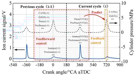
Figure 4.
Concept of ion current/cylinder pressure cooperative combustion diagnosis and control (1500 r/min, IMEP = 0.3 MPa).
By extracting parameters of cylinder pressure or ion current from the previous cycle, such as CA50(i-1), indicated mean effective pressure IMEP(i-1), the maximum cylinder pressure Pmax(i-1), the position of maximum cylinder pressure PosPmax(i-1), the maximum ion current signal Ionmax(i-1), the position of maximum ion current signal PosIonmax(i-1), etc., or extracting parameters of cylinder pressure or ion current from current cycle during NVO, such as the maximum cylinder pressure during NVO PmaxNVO(i), the position of maximum cylinder pressure during NVO PosPmaxNVO(i), the maximum ion current signal during NVO IonmaxNVO(i), the position of maximum ion current signal during NVO PosIonmaxNVO(i), etc., these parameters can be applied as input for combustion parameters prediction of the current cycle during the main combustion, such as CA50(i) or IMEP(i). The combustion prediction method could be simple linear regression or highly nonlinear prediction method such as an artificial neural network.
Apart from feedforward control, a combination of ion current and pressure signals can also be employed for feedback control. Here, a type of abnormal combustion, pre-ignition diagnosis, and control in SI mode is taken as an example. Basically, it is difficult to predict pre-ignition with feedforward control. Hence, a more feasible approach is to diagnose pre-ignition as early as possible before its occurrence and then take measures to control it. The whole process including diagnosis and control needs to be finished in dozens of crank angles, which has higher requirements on calculation speed and computing resources of the control system.
The experiments were performed on a modified second generation EA888 engine. Each of the four cylinders is equipped with different compression ratio pistons. Here, only one cylinder with a compression ratio of 16 is used. Specifications of test engine and equipment are shown in Table 2. The original valve system was replaced with a dual UniValve® system both for the intake and exhaust side [54]. A new cylinder head was designed and manufactured to incorporate the dual UniValve® system. Valve lifts can be continuously adjusted from 0 to 8 mm by electrically rotating control shafts, and valve timing can be continuously adjusted within 60 crank angles (CA) by hydraulic driven cam phasers. Besides, valve lifts and valve timing of intake and exhaust side can be adjusted individually. With this advanced system, HCCI combustion can be easily realized through residual gas recirculation without any intake heating assistance. The intake temperature was controlled 25 ± 1 °C, and the coolant temperature was controlled 80 ± 3 °C in SI mode or 90 ± 3 °C in HCCI mode.
Table 2.
Specifications of test engine and pressure sensor.
Figure 5 shows the schematic diagram of the engine test bench. The engine is equipped with an intake port water injector and a direct fuel injector. The water rail pressure is 0.4 MPa and the fuel rail pressure is 10 MPa. The spark plug is not only used for ignition, but also an ion current sensor. A side-mounted non-water-cooled pressure sensor is employed to record the in-cylinder pressure trace. The engine prototyping control unit is of type National Instruments® CompactRIO, including a field-programmable gate array (FPGA) module, a real-time controller, and reconfigurable input/output (RIO) modules. The reconfigurable chassis with embedded FPGA is the core of the embedded system. It has an ultra-fast timing resolution of 25 ns. The FPGA module is directly connected to RIO modules, which can access RIO circuits at high speed and flexibly implement functions such as timing, triggering, and synchronization. The real-time controller contains an industrial-grade processor that provides multi-rate control, process execution tracking, on-board data storage, and communication with external devices. The RIO modules contain isolation and conversion circuits, signal conditioning functions, which can be directly connected to industrial sensors or actuators, providing a variety of connection options. This prototyping unit is able to control throttle, ignition coil, injector, UniValve® system, and other actuators.
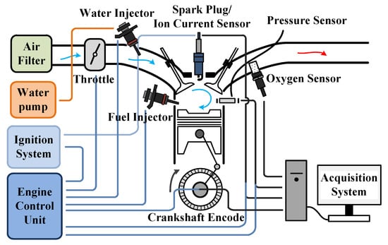
Figure 5.
The schematic diagram of engine test bench.
Apart from basic engine control function, the ion current/cylinder pressure cooperative combustion diagnosis and control algorithm are also implemented on CompactRIO as shown in Figure 6. The ion current and cylinder pressure signals are strictly synchronized into the FPGA chassis via the analog input modules. The FPGA box executes high-speed acquisition of two signals and simple parameters calculation, such as the maximum cylinder pressure and its position, the maximum ion current and its position. For HCCI combustion, the characteristic parameters of ion current and cylinder pressure are extracted both in NVO period and main combustion period. These parameters calculated by FPGA will be sent to the real-time controller using FIFO (first-in-first-out) logic. The real-time controller is responsible for complex parameters calculation such as CA50 or IMEP and control algorithm implementation according to specific control targets. The commands that need to be executed will be returned to the FPGA chassis, and then the RIO modules issue instructions to complete the action execution. The whole process will be finished between tens to hundreds of crankshaft angles, depending on in-cycle or cycle-to-cycle control algorithms. At the same time, manipulated variables such as fuel injection, ignition, valve timing, and valve lifts are also acquired by the real-time controller. Under this circumstance, all parameters extracted from ion current or cylinder pressure signals and manipulated variables are strictly guaranteed to be acquired and recorded by the real-time controller in the form of test data exchange stream (TDMS) files synchronously. These data will be used to verify whether the target actuators are executed correctly.
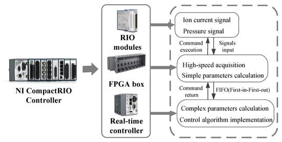
Figure 6.
Structure of ion current/cylinder pressure cooperative combustion diagnosis and control system.
Before applying the system for control, online calculation results should be accurate enough. Figure 7 shows the comparison results between online calculation and offline calculation of three randomly chosen parameters calculated from ion current or cylinder pressure signals. They are CA50, IonmaxNVO, and PosPmaxNVO. The raw data of offline calculation is processed by MATLAB®. A correlation analysis is performed to quantitatively evaluate the accuracy of the online calculation. From Figure 7, it can be seen that the correlation coefficient (r) of three parameters are all higher than 0.9, which belongs to “highly relevant”. The correlation coefficient between offline calculated PosPmaxNVO and online calculated PosPmaxNVO is up to 0.99. Hence, it can be considered that the online calculation results are accurate enough for combustion diagnosis and control application.
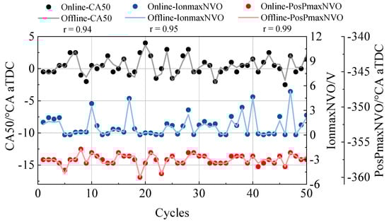
Figure 7.
Comparison between online calculation results and offline calculation results.
4. Application of Ion Current/Cylinder Pressure Cooperative Combustion Diagnosis and Control System
After validating the accuracy of online calculation results, in this chapter, an application case of ion current/cylinder pressure cooperative combustion diagnosis and control system in HCCI mode will be introduced.
Figure 8 shows the CA50 and knock intensity (KI) for 400 consecutive cycles of high load boundary conditions in HCCI mode. When the knock intensity is greater than 0.1 MPa, it indicates that knock has occurred. From Figure 8, it can be seen that the knock intensity of the partial cycle is even over 0.4 MPa, which is four times the acceptable limit. Such a strong knock limits the further increases in load. After analysis, knock is divided into two types. The first type is caused by incomplete combustion in the previous cycle, which is the unique regression characteristic of compression ignition engines. The other type is stochastic knock. There is no obvious warning for this kind of knock, so it is difficult to control.
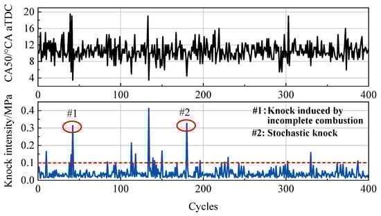
Figure 8.
Engine performance at HCCI high load boundary conditions (1500 r/min, IMEP = 0.4 MPa).
For the first type of knock, the reason is apparent. Unburned fuel of incomplete combustion combines with the regularly injected fuel through internal residual gas recirculation, resulting in excess fuel mass, so early combustion or even knock occurs near the top dead center. Thus, this type of knock can be determined by judging whether the previous cycle is incomplete combustion. The left subfigure of Figure 9 shows the CA50 return map at high load boundary conditions. The light grey points are all measurement data, in which the first type of knock cycle is highlighted by blue points. In this area, it is found that linear regression can be performed, and the correlation coefficient is as high as −0.94. It shows that if incomplete combustion occurred in the previous cycle, there will be a great probability of knock in current cycle. This linear regression can be simply fitted by Equation (1).
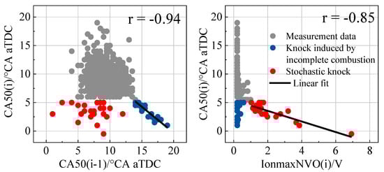
Figure 9.
Judgment basis for two kinds of knock.
Except for knock induced by incomplete combustion, stochastic knock highlighted with red points should also be controlled. Since the previous cycle of stochastic knock is normal combustion, the only information available for combustion prediction comes from the negative valve overlap period. By analyzing the correlation between CA50(i) and the cylinder pressure or ion current signal characteristic parameters during NVO, it is found that the IonmaxNVO(i) has a certain corresponding relationship with CA50(i) as shown in the right subfigure of Figure 9. The IonmaxNVO of most cycles is lower than 1 V, but the IonmaxNVO of stochastic cycles is particularly high. Similarly, linear regression is performed for these cycles and the fitted Equation (2) can be obtained. The correlation coefficient is also as high as −0.85, which belongs to highly correlated. This phenomenon confirms that the ion current signal is more sensitive to low-temperature chemical reaction than cylinder pressure signal. When the fuel reforming process during NVO is excessively strong, a stronger ion current signal during NVO can be observed, which becomes an indication of stochastic knock. Compared to the previous results conducted by Wick [16], whose purpose is only to prevent the knock induced by incomplete combustion of HCCI engine with only cylinder pressure for combustion control, the criterions found in this article can predict not only the knock induced by incomplete combustion but also stochastic knock. This result shows the superiority of ion current/cylinder pressure synergy in combustion diagnosis.
CA50(i) = −0.96* CA50(i-1) + 18.7
CA50(i) = −0.93* IonmaxNVO(i) + 5.4
Figure 10 shows the structure of whole control algorithm including knock judgement criterion and knock suprresion method. Real-time CA50 based on cylinder pressure signal and IonmaxNVO based on ion current signal will be caculated in each cycle. The judgment criterions are CA50(i-1) is greater than CA50threshold or IonmaxNVO(i) is greater than IonmaxNVOthreshold. Knock is consisdered to occur as long as any one of the two judgment criterions is met. It should be noted that the two thresholds need to be calibrated and may be different for different operating conditions or engines. Then CA50 of the next cycle can be linearly estimated by Equation (1) or Equation (2). The predicted CA50 is compared to the target CA50 so that ∆CA50predict can be obtained. This deviation is the advance of the combustion phase of the current cycle compared to the normal combustion cycle. Once ∆CA50predict is determined, reasonbale measures should be taken to supress the knock. In this case, intake water injection is employed. The water injection timing is set as −320 °CA aTDC to ensure thorough atomization and evaporation. From the experimental results, the target water injection width mwater(i) can be linearly estimated by Equation (3).
mwater(i) = (∆CA50predict + 1.22)/1.4
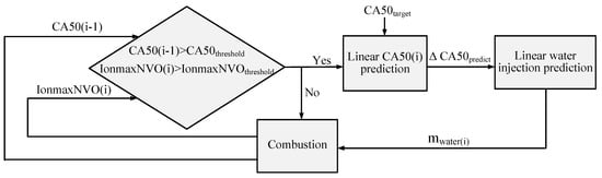
Figure 10.
Structure of control algorithm.
The controller was experimentally validated at 1500 r/min and 0.4 MPa IMEP. Specifically, the pre-injection and main-injection timing is −400 °CA aTDC and −260 °CA aTDC. The pre-injection and main-injection pulse is 0.37 ms and 0.975 ms. The intake and exhaust valve timing is 15 °CA and 45 °CA. In addition, both the intake and exhaust valve lifts are 3 mm. The test process is to continuously acquired 960 cycles of data, and turn on the control at the 481th cycle to compare the changes in engine combustion before and after the control. Figure 11 shows a comparison of water injection, cylinder pressure, and ion current signals of three continuous cycles before and after control. In the left subgraph, when the controller was off, a typical phenomenon that incomplete combustion and knock occurs alternately can be observed. The 97th cycle is a normal combustion cycle. Then incomplete combustion is randomly appeared in the 98th cycle. Later, knock occurs in the 99th cycle because no control measures are taken. An abnormally high ion current signal can also be observed during NVO in this cycle, which also indicated the occurrence of knock.
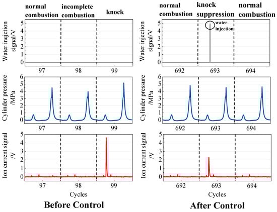
Figure 11.
Water injection, cylinder pressure, and ion current signals of three continuous cycles before and after control.
After the controller was turn on, the 692nd cycle is a normal combustion cycle. Then in the 693rd cycle, a high ion current during NVO can be observed, which is an indication of knock occurrence. Hence, a 5-V transistor-transistor logic (TTL) water injection signal appears in the 693rd cycle at −320 °CA aTDC, which means that in this cycle water injection was activated, and in this cycle, the knock was successfully suppressed. The followed 694th cycle is also a normal combustion cycle.
To get an overall evaluation of controller performance, the variation of CA50, IMEP, and knock intensity before and after control are shown in Figure 12. The standard deviation of CA50 (σCA50), the standard deviation of IMEP (σIMEP), and mean knock intensity are three quantitative evaluation indices of controller performance. In the first 480 cycles, CA50 and IMEP fluctuated due to lacking control measures. The CA50 and IMEP of some cycles significantly deviated from the normal value. Besides, the knock intensity of partial cycles has exceeded the limit of 0.1 MPa. After activating the controller, σCA50 is decreased from 1.88 °CA to 1.75 °CA, σIMEP is decreased from 0.011 MPa to 0.008 MPa, and mean knock intensity is decreased from 0.048 MPa to 0.041 MPa. More importantly, the knock intensity of controlled cycles can be kept lower than accceptable limit. Therefore, with this algorithm, knock can be effectively suppressed and the combustion stability has been improved. In this case, only 3.5% of cycles need water injection control intervention. Compared to the stationary continuous water injection, intermittent water injection can save water consumption and reduce the possibility of engine parts corrosion and oil emulsification.
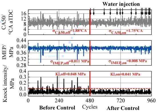
Figure 12.
The variation of CA50, IMEP, and knock intensity before and after control.
5. ANN-Based Ion Current/Cylinder Pressures Cooperative Combustion Prediction
In the previous chapter, one application case is introduced. However, the correlation analysis and controller design are mainly based on manual experience and linear regressions. While the engine is an object with multi-factor coupling and strong nonlinear characteristics, considering the advantages of machine learning in dealing with nonlinear problems, in this section, an artificial neural network model is developed to predict the combustion parameters of HCCI mode.
The schematic diagram of an artificial neural network is shown in Figure 13. In order to simply compare the prediction ability of ion current, cylinder pressure, and a combination of the two, the manipulated variables of all measurements were kept unchanged. Therefore, only ion current and cylinder pressure signals make up the data set. Some important characteristic parameters are extracted from both signals as mentioned in the previous session. During pre-processing, both input and observed output variables will be normalized into the range between (−1, 1). In this study, a simple type of artificial neural network, the feedforward neural network (FFNN), is used. Both the input layer and the output layer are one layer. The optimal number of hidden layers and neurons might be different depending on the number of input variables, which is determined using the map sweeping method and will be introduced in detail later. For more intuitive comparison, the results obtained from the output layer need to be anti-normalized. A Levenberg-Marquardt algorithm (trainlm), which combines the advantages of the Newton–Gaussian method and gradient descent method, is utilized as the training algorithm. This method offers faster convergence and lower mean squared error (MSE) than other algorithms when the number of network weights is not too large. A linear function is employed in the output layer. The whole training process is implemented offline using the ANN toolbox supported by MATLAB®.
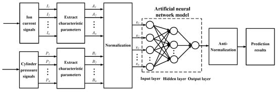
Figure 13.
Schematic diagram of artificial neural network.
We chose 154077 valid cycles to train the artificial neural network model. The overall database is divided into three sets. The validation and the testing set each own 15% of the entire database, while the remaining 70% is used as the training set. In order to compare the prediction performance of the model employing only ion current related-parameters, only cylinder pressure-related parameters, or both, three sets of input variables were selected as shown in Table 3. The input variables of the first model named as ANNIC are only ion current-related parameters, including Ionmax(i-1), PosIonmax(i-1), IonmaxNVO(i), PosIonmaxNVO(i). The input variables of the second model named as ANNCP are only cylinder pressure-related parameters, including CA50(i-1), IMEP(i-1), Pmax(i-1), PosPmax(i-1), PmaxNVO(i), and PosPmaxNVO(i). Meanwhile, the third group named ANNIP combines all the mentioned variables as input variables. The output variable is selected as CA50(i), which is identical for all groups.
Table 3.
The input and out variables of three ANN models.
After the input and output variables are determined, the optimal ANN structure for three models needs to be determined. The approach is to do the map sweeping of hidden layers and neurons. Specifically, the hidden layer sweeps from 1 to 4, and the neurons of each hidden layer sweep from 4 to 10. Then each combination will be automatically trained and the MSE can be calculated with Equation (4):
in which is the observed value of output variables, is the predicted value of output variables, and n is the number of data points.
The cost function as shown in Equation (5) is the evaluation index to determine the optimal ANN structure, which has compromised the training error, validation error, and training duration [55]. The combination with the lowest cost will be the optimal hidden layer and neurons for a specific model.
in which is the MSE of training data set, is the MSE of validation data set, and is the training duration.
Figure 14 shows the cost map of three ANN models. Basically, the difference in cost among various combinations is small. The cost increases with the increase of hidden layers and neurons since the training duration increases significantly. The minimal cost is highlighted with a star symbol. For the ANNIC, the optimal number of the hidden layer is 1 with 9 neurons per layer. For the ANNCP, the optimal number of the hidden layer is 1 with 5 neurons per layer. And For the ANNIP, the optimal number of the hidden layer is 2 with 6 neurons per layer. After optimal network structures have been settled, each ANN model will be trained five times with randomly generated initial matrices. Because different initial matrixes may lead to different final values of matrixes, the model with the lowest cost will be selected and analyzed.
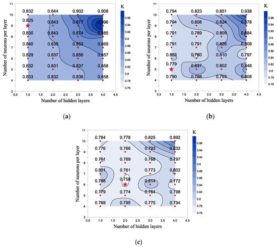
Figure 14.
Cost maps for determination of optimal ANN structure: (a) ANNIC; (b) ANNCP; (c) ANNIP.
To intuitively present the prediction performance of ANN models, the predicted CA50 of testing data set are compared with the experimental results as shown in Figure 15. In case that the model can predict CA50 correctly, the data points should be distributed near the black short dotted line. From Figure 15a, when the input parameters are only ion current-related parameters, the prediction accuracy of the ANNIC model is low. The experimental CA50 changes between −15 °CA aTDC and 15 °CA aTDC, but the predicted CA50 is not sensitive enough and only changes between −5 °CA aTDC and 5 °CA aTDC. When the input variables are only cylinder pressure-related parameters, the prediction accuracy improves significantly as more data distribute near the black short dotted line, but there are also several outlier cycles. When the input variables are a combination of ion current and cylinder pressure-related parameters, almost all data points are concentrated, distributing around the black short dotted line, so the prediction accuracy has been further improved.
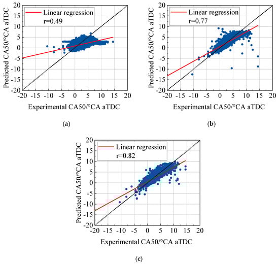
Figure 15.
Comparison of predicted CA50 and experimental CA50: (a) ANNIC; (b) ANNCP; (c) ANNIP.
To get a quantitative comparison result, two evaluation indices are chosen. One is the correlation coefficient between predicted CA50 and experimental CA50, the other is the root mean squared error (RMSE) which has the same dimensions as the output variables. The statistical results are shown in Table 4. The ANNIC model has the worst prediction accuracy as its correlation coefficient is the lowest while the RMSE is the highest. Compared to the ANNIC model, the correlation coefficient of the ANNCP model is enhanced from 0.49 to 0.77, and the RMSE is reduced from 1.40 °CA to 1.06 °CA. For the ANNIP model, it shows the best prediction accuracy as the correlation coefficient further increases from 0.77 to 0.82, at the same time, the RMSE is further reduced from 1.06 °CA to 0.94 °CA.
Table 4.
Prediction performance of three ANN models.
The above results show that on the one hand, the prediction robustness based on the cylinder pressure is better than based on the ion current signal. A reasonable interpretation is that it is a global measurement quantity that is much less sensitive to the boundary condition. However, on the other hand, the results confirmed that the ion current signal can give significant additional information beyond pressure trace. It should be noted that this is another situation different from the application case in the previous section. In the previous section, only by combining both signals, two kinds of knock can be completely predicted. Meanwhile, in this session, the results show that under normal circumstances, the combination of ion current and cylinder pressures still makes sense. Therefore, it is promising to integrate an ANN-based ion current/cylinder pressure cooperative combustion prediction model to the existing ion current/cylinder pressure cooperative combustion diagnosis and control system developed in this article.
6. Conclusions and Outlook
This article summarizes the following conclusions:
- (1)
- Two kinds of ion current detection systems are comprehensively introduced and compared at the hardware level and signal level. In general, the performance of the DC-power ion current detection system is better than that of the capacitive ion circuit detection system both in SI and HCCI modes, so it is more suitable for laboratory research. The biggest advantage of the capacitive ion current detection system is that it is compatible with mainstream ignition systems, so it is more conducive to industrial applications.
- (2)
- The ion current/cylinder pressure cooperative combustion diagnosis and control system is implemented on the engine prototyping control unit. The accuracy of online calculation results has been validated as its correlation coefficient to the offline calculation results is higher than 0.9. One application case of using this system for HCCI abnormal combustion control and stability improvement under high load boundary condition is introduced. After activating the controller, the standard deviation of CA50 is decreased from 1.88 °CA to 1.75 °CA and the standard deviation of IMEP is decreased from 0.011 MPa to 0.008 MPa. More importantly, the knock intensity of all cycles after water injection control is below the acceptable limit. Hence, with this algorithm, the knock can be effectively suppressed and the combustion stability has been improved.
- (3)
- The potential of ion current/cylinder pressure synergy combined with an artificial neural network (ANN) model for combustion prediction has been evaluated. The ANNIC model (only ion current as input) has the worst prediction accuracy. The prediction accuracy of the ANNCP model (only cylinder pressure as input) is significantly improved, whose correlation coefficient is enhanced from 0.49 to 0.77, and the RMSE is reduced from 1.40 °CA to 1.06 °CA. The ANNIP model (both ion current and cylinder pressure as inputs) shows the best prediction accuracy since the correlation coefficient further increases from 0.77 to 0.82 and the RMSE is further reduced from 1.06 °CA to 0.94 °CA. The results confirmed that the ion current signal can give additional information beyond the pressure trace.
For the next step, the ANN-based ion current/cylinder pressure cooperative combustion prediction model will be integrated into the existing ion current/cylinder pressure cooperative combustion diagnosis and control system developed in this article. There will be more application attempts with this system in SI and HCCI modes in the future.
Author Contributions
Conceptualization, D.Z. and L.L.; formal analysis, D.Z.; funding acquisition, J.D., J.A., and L.L.; investigation, D.Z., H.W., S.W., and H.Z.; methodology, D.Z.; project administration, J.D., J.A., and L.L.; resources, J.D., J.A., and L.L.; software, D.Z., J.W., S.W., and H.Z.; supervision, L.L.; writing—original draft, D.Z.; writing—review & editing, J.A. and L.L. All authors have read and agreed to the published version of the manuscript.
Funding
This research was funded by China Natural Science Foundation (No.52076153 & No.51761135105), German Research Association (the joint Sino-German research project “Ion-Current Sensor based Closed-Loop Control of Lean Gasoline Combustion with High Compression Ratio”, No.392430670), and KSPG Professorship Chair of CDHK in Tongji University.
Conflicts of Interest
The authors declare no conflict of interest.
References
- Reitz, R.D.; Ogawa, H.; Payri, R.; Fansler, T.; Kokjohn, S.; Moriyoshi, Y.; Agarwal, A.K.; Arcoumanis, D.; Assanis, D.; Bae, C.; et al. IJER editorial: The future of the internal combustion engine. Int. J. Eng. Res. 2019, 21, 1–8. [Google Scholar] [CrossRef]
- Kalghatgi, G. Is it really the end of internal combustion engines and petroleum in transport? Appl. Energy 2018, 225, 965–974. [Google Scholar] [CrossRef]
- Chu, S.; Majumdar, A. Opportunities and challenges for a sustainable energy future. Nature 2012, 488, 294–303. [Google Scholar] [CrossRef]
- Luo, H.; Nishida, K.; Uchitomi, S.; Ogata, Y.; Zhang, W.; Fujikawa, T. Microscopic behavior of spray droplets under flat-wall impinging condition. Fuel 2018, 219, 467–476. [Google Scholar] [CrossRef]
- Luo, H.; Nishida, K.; Uchitomi, S.; Ogata, Y.; Zhang, W.; Fujikawa, T. Effect of temperature on fuel adhesion under spray-wall impingement condition. Fuel 2018, 234, 56–65. [Google Scholar] [CrossRef]
- Zhou, F.; Fu, J.; Li, D.; Liu, J.; Lee, C.; Yin, Y. Experimental study on combustion, emissions and thermal balance of high compression ratio engine fueled with liquefied methane gas. Appl. Therm. Eng. 2019, 161, 114125. [Google Scholar] [CrossRef]
- Yang, Z.; Miganakallu, N.; Miller, T.; Worm, J.; Naber, J.; Roth, D. Comparing methods for improving spark-ignited engine efficiency: Over-expansion with multi-link cranktrain and high compression ratio with late intake valve closing. Appl. Energy 2020, 262, 114560. [Google Scholar] [CrossRef]
- Doğan, H.E.; Kutlar, O.A.; Javadzadehkalkhoran, M.; Demirci, A. Investigation of Burn Duration and NO Emission in Lean Mixture with CNG and Gasoline. Energies 2019, 12, 4432. [Google Scholar] [CrossRef]
- Gong, C.; Yi, L.; Zhang, Z.; Sun, J.; Liu, F. Assessment of ultra-lean burn characteristics for a stratified-charge direct-injection spark-ignition methanol engine under different high compression ratios. Appl. Energy 2020, 261, 114478. [Google Scholar] [CrossRef]
- Zhao, L.; Qi, W.; Wang, X.; Su, X. Potentials of EGR and lean mixture for improving fuel consumption and reducing the emissions of high-proportion butanol-gasoline engines at light load. Fuel 2020, 266, 116959. [Google Scholar] [CrossRef]
- Zhen, X.; Li, X.; Wang, Y.; Liu, D.; Tian, Z.; Wang, Y. Effects of the initial flame kernel radius and EGR rate on the performance, combustion and emission of high-compression spark-ignition methanol engine. Fuel 2020, 262, 116633. [Google Scholar] [CrossRef]
- Esfahanian, V.; Salahi, M.M.; Gharehghani, A.; Misrsalim, M. Extending the lean operating range of a premixed charged compression ignition natural gas engine using a pre-chamber. Energy 2019, 119, 1181–1194. [Google Scholar] [CrossRef]
- Tsuboi, S.; Miyokawa, S.; Matsuda, M.; Yokomori, T.; Iida, N. Influence of spark discharge characteristics on ignition and combustion process and the lean operation limit in a spark ignition engine. Appl. Energy 2019, 250, 617–632. [Google Scholar] [CrossRef]
- Pan, M.; Zhu, Y.; Bian, X.; Liang, Y.; Lu, F.; Ban, Z. Theoretical analysis and comparison on supercritical CO2 based combined cycles for waste heat recovery of engine. Energy Convers. Manag. 2020, 219, 113049. [Google Scholar] [CrossRef]
- Zhu, S.; Zhang, K.; Deng, K. A review of waste heat recovery from the marine engine with highly efficient bottoming power cycles. Renew. Sustain. Energy Rev. 2020, 120, 113049. [Google Scholar] [CrossRef]
- Wick, M.; Bedei, J.; Gordon, D.; Wouters, C.; Lehrheuer, B.; Nuss, E.; Andert, J.; Koch, C. In-cycle control for stabilization of homogeneous charge compression ignition combustion using direct water injection. Appl. Energy 2019, 240, 1061–1074. [Google Scholar] [CrossRef]
- Schmitt, S.; Wick, M.; Wouters, C.; Ruwe, L.; Graf, I.; Andert, J.; Hansen, N.; Pischinger, S.; Höinghaus, K. Effects of water addition on the combustion of iso-octane investigated in laminar flames, low-temperature reactors, and an HCCI engine. Combust. Flame 2020, 212, 433–447. [Google Scholar] [CrossRef]
- Onishi, S.; Jo, S.; Shoda, K.; Jo, P.; Kato, S. Active Thermo-Atmosphere Combustion (ATAC)—A New Combustion Process for Internal Combustion Engines; SAE Technical Paper 790501; SAE International: Detroit, MI, USA, 1979. [Google Scholar]
- Noguchi, M.; Tanaka, Y.; Tanaka, T.; Takeuchi, Y. A Study on Gasoline Engine Combustion by Observation of Intermediate Reactive Products during Combustion; SAE Technical Paper 790840; SAE International: Detroit, MI, USA, 1979. [Google Scholar]
- Sauter, J.; Lee, C.; Ra, Y.; Reitz, R. Model Parameter Sensitivity of Mixing and UHC/CO Emissions in a PPCI, Low-Load Optical Diesel Engine; SAE Technical Paper 2011-01-0844; SAE International: Detroit, MI, USA, 2011. [Google Scholar]
- Reezaei, S.; Zhang, F.; Xu, H.; Ghafourian, A.; Herreros, J.; Shuai, S. Investigation of two-stage split-injection strategies for a Dieseline fuelled PPCI engine. Fuel 2013, 107, 299–308. [Google Scholar] [CrossRef]
- Ansari, E.; Shahbakhti, M.; Naber, J. Optimization of performance and operational cost for a dual mode diesel-natural gas RCCI and diesel combustion engine. Appl. Energy 2018, 231, 549–561. [Google Scholar] [CrossRef]
- Liu, X.; Kokjohn, S.; Li, Y.; Wang, H.; Li, H.; Yao, M. A numerical investigation of the combustion kinetics of reactivity controlled compression ignition (RCCI) combustion in an optical engine. Fuel 2019, 241, 753–766. [Google Scholar] [CrossRef]
- Kawamura, Y.; Shinshi, M.; Sato, H.; Takahashi, N.; Irlyama, M. MBT Control through Individual Cylinder Pressure Detection; SAE Technical Paper 881779; SAE International: Detroit, MI, USA, 1988. [Google Scholar]
- Draper, C.S.; Li, Y.T. Principles of Optimalizing Control Systems and an Application to the Internal Combustion Engine; American Society of Mechanical Engineers: New York, NY, USA, 1951. [Google Scholar]
- Fujii, I.; Yagi, S.; Kawai, M.; Yoshikawa, H. MBT Control Utilizing Crank Angle of Maximum Combustion Pressure; SAE Technical Paper 890759; SAE International: Detroit, MI, USA, 1989. [Google Scholar]
- Zhu, G.; Daniels, C.; Winkelman, J. MBT Timing Detection and its Closed-Loop Control Using In-Cylinder Pressure Signal; SAE Technical Paper 2003-01-3266; SAE International: Detroit, MI, USA, 2003. [Google Scholar]
- Houpt, P.; Andreadakis, S. Estimation of Fuel-Air Ratio from Cylinder Pressure in Spark Ignited Engines; SAE Technical Paper 830418; SAE International: Detroit, MI, USA, 1983. [Google Scholar]
- Tunestål, P.; Hedrick, J.K. Cylinder air/fuel ratio estimation using net heat release data. Control Eng. Pract. 2003, 11, 311–318. [Google Scholar] [CrossRef]
- Kumar, M.; Shen, T. In-cylinder pressure-based air-fuel ratio control for lean burn operation mode of SI engines. Energy 2017, 120, 106–116. [Google Scholar] [CrossRef]
- Randall, K.; Powell, J. A Cylinder Pressure Sensor for Spark Advance Control and Knock Detection; SAE Technical Paper 790139; SAE International: Detroit, MI, USA, 1979. [Google Scholar]
- Sawamoto, K.; Kawamura, Y.; Kita, T.; Matsushita, K. Individual Cylinder Knock Control by Detecting Cylinder Pressure; SAE Technical Paper 871911; SAE International: Detroit, MI, USA, 1987. [Google Scholar]
- Ravaglioli, V.; Bussi, C. Model-Based Pre-Ignition Diagnostics in a Race Car Application. Energies 2019, 12, 2277. [Google Scholar] [CrossRef]
- Cho, S.; Park, J.; Song, C.; Oh, S.; Lee, S.; Kim, M.; Min, K. Prediction Modeling and Analysis of Knocking Combustion using an Improved 0D RGF Model and Supervised Deep Learning. Energies 2019, 12, 844. [Google Scholar] [CrossRef]
- Shimasaki, Y.; Kobayashi, M.; Sakamoto, H.; Ueno, M.; Hasegawa, M.; Yamaguchi, S. Study on Engine Management System Using in-Cylinder Pressure Sensor Integrated with Spark Plug; SAE Technical Paper 2004-01-0519; SAE International: Detroit, MI, USA, 2004. [Google Scholar]
- Cesario, N.; Tagliatatela, F.; Lavorgna, M. Methodology for misfire and partial burning diagnosis in SI engines. IFAC PapersOnline 2006, 4, 1024–1028. [Google Scholar] [CrossRef]
- Gürbüz, H. Experimental evaluation of combustion parameters with ion-current sensor integrated to fast response thermocouple in SI engine. J. Energy Eng. 2017, 143, 04016046. [Google Scholar] [CrossRef]
- Zhu, D.; Chen, Z.; Chao, Y.; Deng, J.; Li, L. Primary Study on the Transient EGR Control of GDI Turbocharged Engine by Ion Sensing Technology. IFAC PapersOnLine 2018, 51, 146–153. [Google Scholar] [CrossRef]
- Badawy, T.; Rai, N.; Singh, J.; Bryzik, W.; Henein, N. Effect of design and operating parameters on the ion current in a single-cylinder diesel engine. Int. J. Eng. Res. 2011, 12, 601–616. [Google Scholar] [CrossRef]
- Gao, Z.; Liu, B.; Gao, H.; Meng, X.; Tang, C.; Wu, X.; Huang, Z. The correlation between the cylinder pressure and the ion current fitted with a Gaussian algorithm for a spark ignition engine fuelled with naturalgas–hydrogen blends. Proc. Inst. Mech. Eng. D J. Automob. Eng. 2014, 228, 1480–1490. [Google Scholar] [CrossRef]
- Strandh, P.; Christensen, M.; Bengtsson, J.; Johansson, R.; Vressner, A.; Tunestål, P.; Johansson, B. Ion Current Sensing for HCCI Combustion Feedback; SAE Technical Paper 2003-01-3216; SAE International: Detroit, MI, USA, 2003. [Google Scholar]
- Xie, H.; Wu, Z.; Sun, Y. Ion current characteristics of gasoline HCCI combustion process based on internal EGR. J. Tianjin Univ. 2008, 41, 547–552. [Google Scholar]
- Dong, G.; Li, L.; Zhu, D.; Deng, J. Ion Current Features of HCCI Combustion in a GDI Engine. Automot. Innov. 2019, 2, 305–313. [Google Scholar] [CrossRef]
- Hellring, M.; Munther, T.; Rögnvaldsson, T.; Wickström, N.; Carlsson, C.; Larsson, M.; Nytomt, J. Spark Advance Control Using the Ion Current and Neural Soft Sensors; SAE Technical Paper 1999-01-1162; SAE International: Detroit, MI, USA, 1999. [Google Scholar]
- Reinmann, R.; Saitzkoff, A.; Mauss, F. Local Air-Fuel Ratio Measurements Using the Spark Plug as an Ionization Sensor; SAE Technical Paper 970856; SAE International: Detroit, MI, USA, 1997. [Google Scholar]
- Auzins, J.; Johansson, H.; Nytomt, J. Ion-Gap Sense in Misfire Detection, Knock and Engine Control; SAE Technical Paper 950004; SAE International: Detroit, MI, USA, 1995. [Google Scholar]
- Fan, Q.; Bian, J.; Lu, H.; Tong, S.; Li, L. Misfire detection and re-ignition control by ion current signal feedback during cold start in two-stage direct-injection engines. Int. J. Eng. Res. 2014, 15, 37–47. [Google Scholar] [CrossRef]
- Chao, Y.; Chen, X.; Deng, J.; Hu, Z.; Wu, Z.; Li, L. Additional injection timing effects on first cycle during gasoline engine cold start based on ion current detection system. Appl. Energy 2018, 221, 55–66. [Google Scholar] [CrossRef]
- Liu, Y.; Deng, J.; Hu, Z.; Li, L. In-cycle combustion feedback control for abnormal combustion based on digital ion current signal. Int. J. Eng. Res. 2018, 19, 241–249. [Google Scholar] [CrossRef]
- Collings, N.; Dinsdale, S.; Eade, D. Knock Detection by Means of the Spark Plug; SAE Technical Paper 860635; SAE International: Detroit, MI, USA, 1986. [Google Scholar]
- Laganá, A.; Lima, L.; Justo, J.; Arruda, B.; Santos, M. Identification of combustion and detonation in spark ignition engines using ion current signal. Fuel 2018, 227, 469–477. [Google Scholar] [CrossRef]
- Tong, S.; Li, H.; Yang, Z.; Deng, J.; Hu, Z.; Li, L. Cycle Resolved Combustion and Pre-Ignition Diagnostic Employing Ion Current in a PFI Boosted SI Engine; SAE Technical Paper 2015-01-0881; SAE International: Detroit, MI, USA, 2015. [Google Scholar]
- Wang, J.; Hu, Z.; Zhu, D.; Ding, W.; Li, L.; Yan, W.; Jian, T.; Chen, L. In Cycle Pre-Ignition Diagnosis and Super-Knock Suppression by Employing Ion Current in a GDI Boosted Engine; SAE Technical Paper 2020-01-1148; SAE International: Detroit, MI, USA, 2020. [Google Scholar]
- Flierl, R.; Gollasch, D.; Knecht, A.; Hannibal, W. Improvements to a Four Cylinder Gasoline Engine through the Fully Variable Valve Lift and Timing System UniValve®; SAE Technical Paper 2006-01-0223; SAE International: Detroit, MI, USA, 2006. [Google Scholar]
- Wick, M.; Bedei, J.; Andert, J.; Lehrheuer, B.; Pischinger, S.; Nuss, E. Dynamic measurement of HCCI combustion with self-learning of experimental space limitations. Appl. Energy 2020, 262, 114364. [Google Scholar] [CrossRef]


Publisher’s Note: MDPI stays neutral with regard to jurisdictional claims in published maps and institutional affiliations. |
© 2020 by the authors. Licensee MDPI, Basel, Switzerland. This article is an open access article distributed under the terms and conditions of the Creative Commons Attribution (CC BY) license (http://creativecommons.org/licenses/by/4.0/).