Article

Switching Sequence Model Predictive Direct Torque Control of IPMSMs for EVs in Switch Open-Circuit Fault-Tolerant Mode

1
School of Science and Technology, Gunma University, Kiryu, Gunma 376-8515, Japan
2
School of Energy Engineering, Yulin University, Yulin 719100, China
3
School of Electrical Energy and Power Engineering, YangZhou University, Yangzhou 225127, China
*
Author to whom correspondence should be addressed.
Energies 2020, 13(21), 5593; https://doi.org/10.3390/en13215593
Submission received: 15 September 2020 / Revised: 21 October 2020 / Accepted: 23 October 2020 / Published: 26 October 2020
(This article belongs to the Section E: Electric Vehicles)

Abstract

:
A switching sequence model predictive direct torque control (MPDTC) of IPMSMs for EVs in switch open-circuit fault-tolerant mode is studied in this paper. Instead of selecting one space vector from the possible four space vectors, the proposed MPDTC method selects an optimized switching sequence from two well-designed switching sequences, including three space vectors, according to a new designed cost function of which the control objectives have been transferred to the dq-axes components of the stator flux-linkage under the maximum-torque-per-ampere control. The calculation method of the durations of the adopted space vectors in the optimized switching sequence is studied to realize the stator flux-linkage reference tracking. In addition, the capacitor voltage balance method, by injecting a dc offset to the current of fault phase, is given. Compared with the conventional MPDTC method, the complicated weighting factors designing process is avoided and the electromagnetic torque ripples can be greatly suppressed. The experimental results prove the effectiveness and advantages of the proposed scheme.

1. Introduction

The drive system of interior permanent magnet synchronous motors (IPMSMs) [1,2] based on two-level voltage source inverters (2L-VSIs) [3,4] has become one of the mainstream speed control schemes for electric vehicles (EVs) due to advantages, such as high efficiency, excellent speed regulation performance, and high power density. In order to improve the security of EVs, the functional safety of the drive system has gradually become one of the research hotspots. According to the failure mode analysis of the drive system [5], it is noted that the switch open-circuit faults of the 2L-VSI can have catastrophic consequences. In some hazardous environments, such as on highway or crowded roads, it is desirable that the 2L-VSI can continuously operate in the case of switch open-circuit failures. Thus, the fault-tolerant control of the 2L-VSI, which allows the EVs to work in the limp-home mode [6,7], is one of the key issues to ensure functional safety.
In the switch open-circuit fault-tolerant mode, the remedial methods consist of hardware and software reconfigurations. For the hardware reconfigurations, an auxiliary fourth leg is added to the 2L-VSI topology [8]. However, the cost, volume, and weight are increased, which are limited in the EV applications. Three-phase and four-switch inverters (3P4SIs) [9] can realize the switch open-circuit fault-tolerant control without increasing the cost, volume, and weight, and thus, it has outstanding advantages in the field of EVs. After an open-circuit fault is detected and located with the fault-detection strategy [10,11], the four normal switches continue to work by connecting the dc bus midpoint to the faulty phase with bidirectional thyristors.
For the software reconfigurations in the case where 3P4SIs are adopted as the fault-tolerant topology, the existing studies can be divided into three aspects according to the control strategies, i.e., flux-oriented control (FOC) with pulse-width modulation (PWM) [12,13,14], direct torque control (DTC) [15,16], and model predictive control (MPC) [17,18,19,20,21,22]. The above three control strategies all face the same problems, namely torque ripple suppression and capacitor voltage balance. In [12], a hybrid space vector PWM is proposed to minimize the torque ripples of the FOC by selecting optimized equivalent zero vectors. To suppress the second periodic torque ripple caused by the fluctuations of the capacitor voltages of the dc-link, a proportional integral resonant (PIR) controller is utilized for the FOC method [13]. In [14], the current reconstruction strategy using a single current sensor for 3P4SIs with FOC is studied and the errors of the sampled currents are compensated according to the current change rates under different voltage vectors. Owing to one phase winding being directly connected with the dc-link midpoint during the operation of 3P4SIs, it has been found that the predicted stator flux imbalance of DTC may be caused by unbalanced inverter voltage drop in [15], which will increase the torque ripple. A compensation scheme considering the forward voltage-drop of the switches is proposed for the DTC of 3P4SIs.
MPC strategies have the ability to deal with system constraints, multi-objective optimization, and multivariable control problems, and have been widely used in the control of power electronic converters. For the conventional MPC methods, the future values of the state variable are predicted and the space vector that minimizes the predesigned cost function is selected [17,18]. However, there are some problems to be solved for the conventional MPC methods. Firstly, the number of the space vectors has been decreased from seven to four in the switch-open fault-tolerant mode, and it is difficult to ensure the multi-objective control performance by selecting only one space vector from four space vectors, which will cause serious torque, flux, and current ripples. Secondly, the design process of the weighting factors in the cost function is complicated owing to the dimensions of the control objectives not being identical. Thirdly, the switching frequency of the conventional MPC is usually far smaller than the sampling frequency and it is not fixed, which makes the filter design complicated. An improved MPC for 3P4SIs connected to surface permanent magnet synchronous generators by increasing the adopted space vectors is studied in [19] to minimize the current reference tracking error. A 3P4SI operation of the grid-side converter of the doubly fed induction generator with the three-vector MPC strategy is studied in [20], where three space vectors are adopted to decrease the ripples of the control variables and make the switching frequency fixed. However, the methods in [19,20] are complicated to implement and the corresponding control strategy for IPMSMs has not been studied. To avoid the complicated weighting factor tuning work, a simplified model predictive flux control with capacitor voltage offset suppression for 3P4SIs is proposed in [21], and the stator flux-linkage is taken as the only control term in the cost function. An improved model predictive flux control based on the id = 0 control mode is studied in [22], where a reference stator flux vector is obtained to represent the reference flux, the reference torque, and the capacitor voltage offset. Nevertheless, the methods in [21,22] only adopt one space vector in a single control period, and the electromagnetic torque ripples reduction has not been considered. For EVs where IPMSMs are coupled to gearboxes, the electromagnetic torque ripples can excite gearbox oscillations, which may seriously reduce the driving comfort.
In this paper, a switching sequence model predictive direct torque control (MPDTC) of IPMSMs for EVs in switch open-circuit fault-tolerant mode is proposed. The stator flux-linkage reference calculation method under maximum-torque-per-ampere (MTPA) control is given. Two switching sequences including three space vectors are designed according to the features of the space vector diagram. Instead of selecting one space vector from the possible four space vectors, the proposed MPDTC method selects an optimized switching sequence from the well-designed two switching sequences according to a new designed cost function without weighting factors. Then, the durations of the adopted space vectors in the optimized switching sequence are calculated to realize the stator flux-linkage reference tracking. In addition, the capacitor voltage balance method by injecting a dc offset to the current of fault phase is studied. Compared with the conventional MPDTC method, the complicated weighting factors designing process is avoided and the electromagnetic torque ripples can be greatly suppressed. An experimental prototype is established, and the experimental results prove the effectiveness and advantages of the proposed scheme.

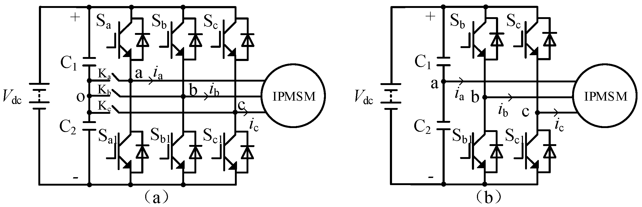
2. Conventional MPDTC of IPMSM for EV in Switch Open-Circuit Fault-Tolerant Mode

The speed regulation system of EVs on the basis of IPMSMs is shown in Figure 1a, where Vdc is the dc-link voltage; C1 and C2 are the upper and lower capacitors; and Sj and Sj1 (j = a, b, c) are the up and low switches, which are composed of insulated gate bipolar transistors (IGBTs) and antiparallel diodes. The energy of the lithium battery pack is transmitted to the IPMSM through the 2L-VSI. To realize the fault-tolerant control of switch-open-circuit fault, three bi-directional thyristors Ka, Kb, and Kc are added between the middle point of the dc-link capacitors (‘o’ as defined in Figure 1a) and the output terminal of the VSI. In normal operation mode, Ka, Kb, and Kc are all in off state, and when one of the phases has an open-circuit fault, the bidirectional thyristor of the corresponding phase is closed, and the output terminal of the fault phase is connected to the middle point of the dc-link capacitors to realize the circuit reconstruction. As an example, the equivalent fault-tolerant circuit in the case where either Sa or Sa1 is open is shown in Figure 1b, which is the so-called 3P4SI.
In Figure 1b, the terminal voltage of phase a is 0 because it is directly connected to the midpoint of the dc-link capacitors, while for phases b and c, the terminal voltage is equal to the voltage of C1 (Vc1) with Sj switching on, and it is equal to the negative voltage of C2 (-Vc2) with Sj switching off. The switching states are defined as ‘1’ and ‘0’ for the former and latter cases, respectively. The combination of the switching states of phases b and c, as shown in Figure 2b, can form four space vectors in the two-phase static coordinate system (α-β), i.e., V1V4. In Figure 2b, it is assumed that Vc1 is equal to Vc2. Taking V2 as an example, the corresponding switching state of phase b is 1 and the one of phase c is 0. By comparing the space vector diagrams in normal mode and in switch-open fault-tolerant mode as shown in Figure 2, the number of space vectors was decreased from 7 to 4.
The voltage and flux equations of IPMSMs are given in (1) and (2), where ud/uq, id/iq, Ld/Lq, Ψd/Ψq, are the dq-axes voltages, currents, inductances, and stator flux-linkages, respectively, Rs is the stator resistance, ωe is the electric angular velocity, and Ψf is the permanent magnet flux linkage:
[ u d u q ] = R s [ i d i q ] + [ L d 0 0 L q ] d d t [ i d i q ] + [ ω e L q i q ω e L d i d + ω e Ψ f ] ,
[ Ψ d Ψ q ] = [ L d 0 0 L q ] [ i d i q ] + [ Ψ f 0 ] .
The current predictive equations can be obtained by discretizing (1) and they are given in (3) and (4), where Ts is the sampling period and k is the number of Ts:
i d ( k + 1 ) = ( 1 R T s L d ) i d ( k ) + ω e T s i q ( k ) L q L d + T s L d u d ( k ) ,
i q ( k + 1 ) = ( 1 R T s L q ) i q ( k ) ω e T s i d ( k ) L q L d + T s L q u q ( k ) ω e T s ω f L q .
Substituting (3) and (4) into (2), the stator flux-linkage predictive equations are given in (5) and (6):
Ψ d ( k + 1 ) = L d i d ( k + 1 ) + Ψ f ,
Ψ q ( k + 1 ) = L q i q ( k + 1 ) .
Then, the amplitude of the stator flux-linkage is calculated as follows:
Ψ s ( k + 1 ) = Ψ d ( k + 1 ) 2 + Ψ q ( k + 1 ) 2 .
In addition, the electromagnetic torque can be predicted according to (8), where Pn is the pole pairs:
T e ( k + 1 ) = 1.5 P n i q ( k + 1 ) [ Ψ f + ( L d L q ) i d ( k + 1 ) ] .
Because the midpoint of the dc-link capacitors is connected with phase a, the difference between the voltage of C1 and C2 (Vc_e) can be calculated by (9):
C d ( V c 1 V c 2 ) d t = C d V c _ e d t = i a ,
where Vc1, Vc2 are the voltage of C1 and C2, and ia is the current of phase ‘a’. Then, the predictive equation of Vc_e is given in (10):
V c _ e ( k + 1 ) = V c _ e ( k ) + i a T s C .
For the conventional MPDTC of IPMSMs for EVs in switch-open fault-tolerant mode, the controlled variables, including the stator flux, the electromagnetic torque, and the difference between the voltage of C1 and C2 for the four space vectors as shown in Figure 2b, are predicted according to (7), (8), and (10), respectively. Then, the cost function as given in (11) is calculated for each prediction, where T e * , Ψ s * are the reference of electromagnetic torque and stator flux; and λ 1 , λ 2 , and λ 3 are the weighting factors. At last, the space vector that minimizing the cost function is selected as the optimized solution:
g = λ 1 | T e * T e ( k + 1 ) | + λ 2 | Ψ s * Ψ s ( k + 1 ) | + λ 3 | V c _ e | .
However, there are some drawbacks for the conventional MPDTC method. Firstly, the number of space vectors has been decreased from 7 to 4 in the switch-open fault-tolerant mode, and the torque and flux ripples become a serious problem owing to the number of the selectable space vectors to optimize the three objectives in (11) has been decreased by 42.85%. Secondly, the design process of λ 1 , λ 2 , and λ 3 is complicated owing to the dimensions of Te, Ψ s , and Vc_e not being identical. Thirdly, the switching frequency of the conventional MPDTC is usually far smaller than the sampling frequency (1/Ts) and it is not fixed, which makes the filter design complicated.

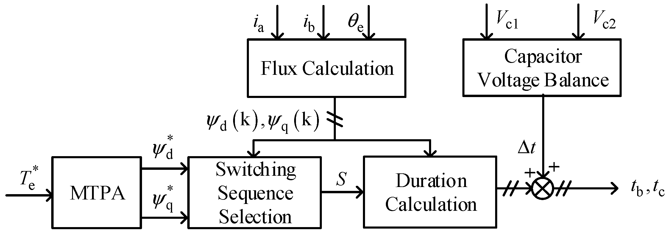
3. Switching Sequence MPDTC of IPMSM for EV in Switch Open-Circuit Fault-Tolerant Mode

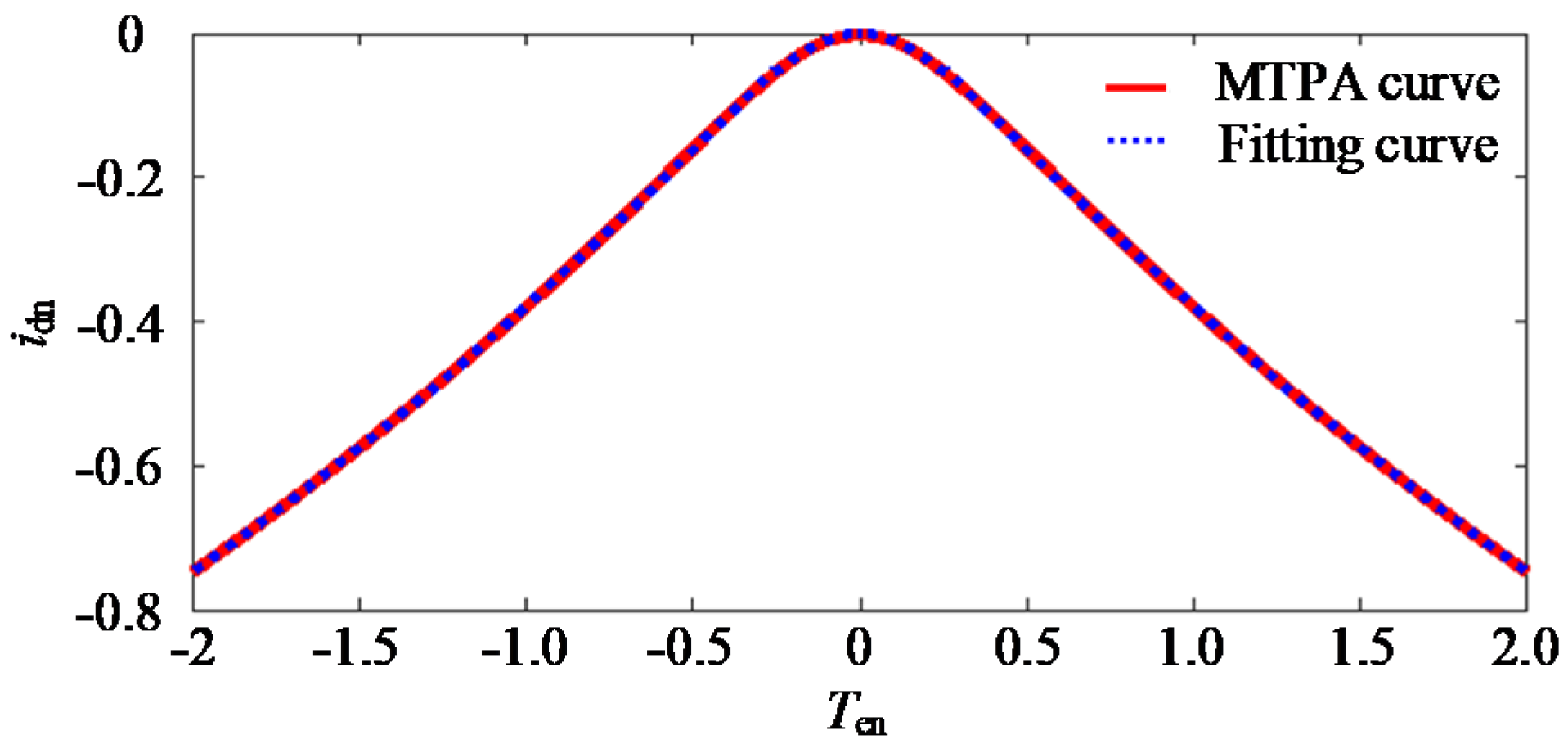
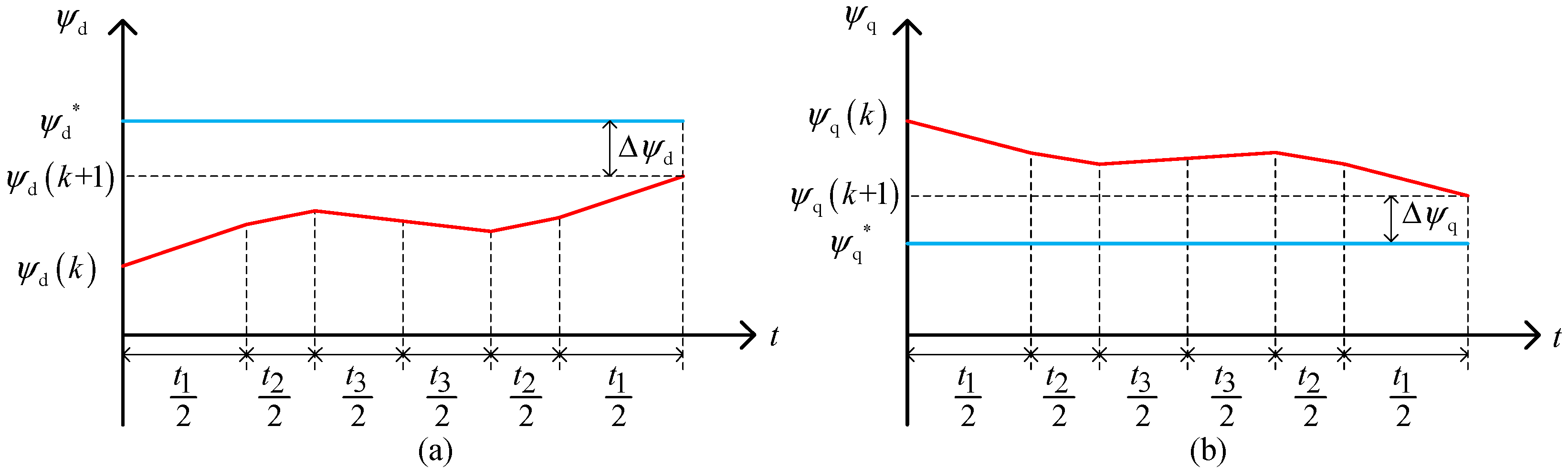
3.1. Stator Flux-Linkage Calculation under MTPA Control

The electromagnetic torque equation is given in (12) with a simplified form, where T e n * , idn, and iqn can be calculated by (13). The base value of the current and electromagnetic torque is defined in (14):
T e n * = i q n ( 1 i d n ) ,
{ T e n * = T e * T e B i d n = i d I B i q n = i q I B ,
{ I B = Ψ f ( L q L d ) T e B = 1.5 P n Ψ f I B .
The efficiency of the speed control system is one of the key indicators of EVs, which is of great significance to the improvement of driving mileage and energy saving. Efficiency optimization of IPMSMs is achieved through MTPA control, of which the relationship between Ten and idn can be obtained in (15) by making T e n * i d n equal to 0:
| T e n * | = i d n ( i d n 1 ) 3 .
To realize the MTPA control, the inverse function of (15) is needed. However, it is hard to obtain the analytic formula owing to (15) is a high-order nonlinear equation. A fitting function as shown in (16) is given to calculate idn with a specific T e n * . Both the MTPA and the fitting curves are plotted in Figure 3, and the two curves are nearly in coincidence, which indicates the effectiveness of the fitting function:
i d n = { 0 , | T e n * | 0.02 0.7272 ( T e n * ) 2 0.0403 T e n * + 0.0013 , | T e n * | 0.24 0.0284 ( T e n * ) 2 0.4769 T e n * + 0.0694 , | T e n * | 1.3 0.039 ( T e n * ) 2 0.4828 T e n * + 0.0612 , e l s e   ,
i d n = { 0 , | T e n * | 0.02 0.7272 ( T e n * ) 2 0.0403 T e n * + 0.0013 , | T e n * | 0.24 0.0284 ( T e n * ) 2 0.4769 T e n * + 0.0694 , | T e n * | 1.3 0.039 ( T e n * ) 2 0.4828 T e n * + 0.0612 , e l s e .
After calculating idn, iqn can be obtained by (17) according to (12):
i q n = T e n * ( 1 i d n ) .
Furthermore, the stator flux-linkage references in the synchronous rotating coordinate axes for a specific T e * can be calculated by (18) and (19) to realize the MTPA control:
Ψ d * = L d i d n I B + Ψ f ,
Ψ q * = L q i q n I B .
That is to say, the control objectives can be transferred to Ψ d * and Ψ q * from T e * and Ψ s * under the MTPA control.

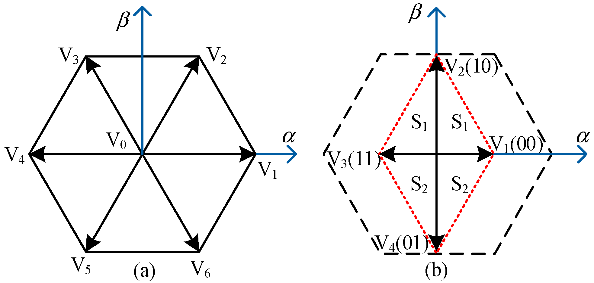
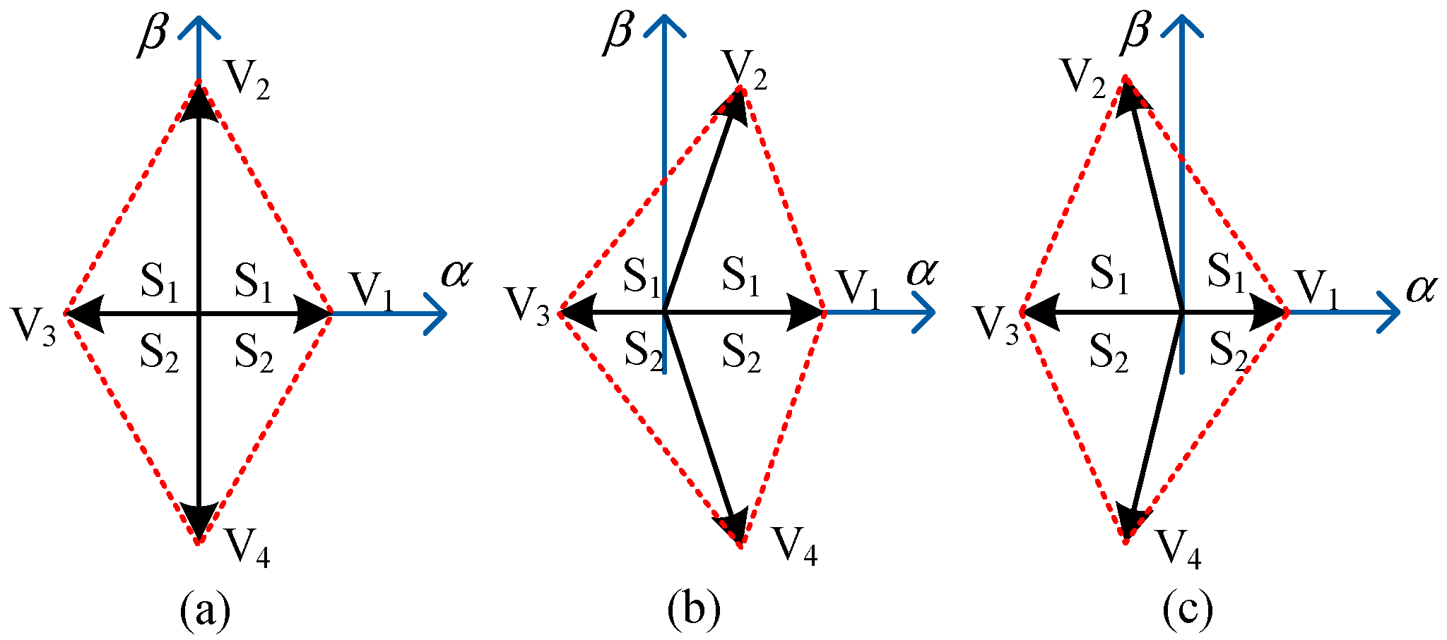
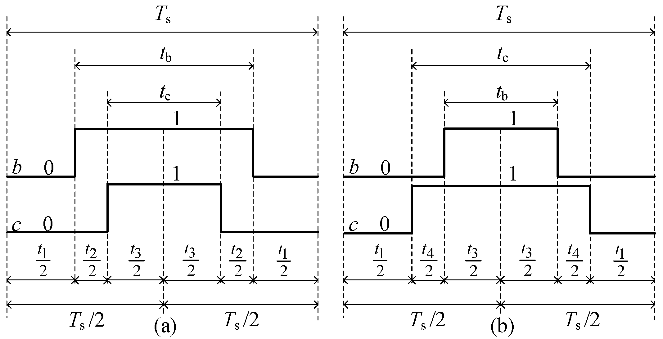
3.2. Switching Sequence Selection

In Figure 2b, the space vector diagram can be divided into 2 sectors, i.e., S1 and S2. Sector S1 is above the α-axis, and it consists of V1, V2, and V3. Sector S2 is below the α-axis, and it consists of V1, V3, and V4. As shown in Figure 4b,c, the positions of V1 and V3 are also lined in the α-axis in the case where Vc1 is not equal to Vc2, and thus, the sector definition method can be applied in the three cases shown in Figure 4.
The switching sequences in S1 and S2 can be designed as Figure 5 according to the nearest-three-vectors (NTVs) principle. In the sector S1, V1, V2, and V3 are selected as the NTVs, and the corresponding switching sequence is shown in Figure 5a. However, in the sector S2, V1, V3, and V4 are selected as the NTVs, and the corresponding switching sequence is shown in Figure 5b. The two cases in Figure 5a,b are defined as the switching sequence I and II, respectively.
In Figure 5, t1t4 are the durations of V1V4, and tb and tc are the durations of state ‘1’ of phase ‘b’ and ‘c’, respectively. For the switching sequence I, tb is bigger than tc and the size-relation of tb and tc is opposite for the switching sequence II.
It can be seen from Figure 5 that both the switching sequences adopt V1 and V3, the difference is that the switching sequence I adopts V2 while the switching sequence II adopts V4. The optimized switching sequence can be selected according to (20) where a new evaluation criteria (g1) is defined in (21). If S is I, the switching sequence I is selected; otherwise, the switching sequence II is selected:
S = { I ,    g 1 ( V 2 ) < g 1 ( V 4 ) II ,    g 1 ( V 2 ) g 1 ( V 4 ) ,
g 1 = ( Ψ d * Ψ d ( k + 1 ) ) 2 + ( Ψ q * Ψ q ( k + 1 ) ) 2 .
According to the part A of this section, the control objectives of tracking of T e * and Ψ s * under the MTPA control can be transferred to the tracking of Ψ d * and Ψ q * . Thus, the optimized switching sequence selecting method in (20) can ensure the optimization of the electromagnetic torque and stator flux.

3.3. Duration Calculation

After determining the switching sequence type, the durations of the adopted space vectors should be calculated to realize the tracking of Ψ d * and Ψ q * . Taking the switching sequence I as an example, Figure 6 shows one of the possible trajectories of Ψ d and Ψ q .
With the switching sequence I, the difference between the reference and predicted stator flux in the synchronous rotating coordinate can be calculated by (22):
{ Δ Ψ d = Ψ d * ( Ψ d ( k ) + k 1 d t 1 + k 2 d t 2 + k 3 d t 3 ) Δ Ψ q = Ψ q * ( Ψ q ( k ) + k 1 q t 1 + k 2 q t 2 + k 3 q t 3 ) ,
where k1d, k2d, and k3d are the slopes of Ψ d with V1, V2, and V3 and k1q, k2q, and k3q are the slopes of Ψ q with V1, V2, and V3. They can be calculated by (23) and (1):
{ k j d = L d d i d d t | ( u d = V j d ) k j q = L q d i q d t | ( u q = V j q ) ,
where j = 1, 2, 3, 4 and Vid, Viq are the d,q-axes component of space vector Vj. According to Figure 5a, (24) can be obtained:
{ t 1 = T s t b t 2 = t b t c t 3 = t c .
By substituting (24) in (22), (22) can be written as (25):
{ Δ Ψ d = Ψ d * ( Ψ d ( k ) + k 1 d ( T s t b ) + k 2 d ( t b t c ) + k 3 d t c ) Δ Ψ q = Ψ q * ( Ψ q ( k ) + k 1 q ( T s t b ) + k 2 q ( t b t c ) + k 3 q t c ) .
The target of the duration calculation is to determine the durations ta and tb in order to minimize the ripples of Ψ d and Ψ q under MTPA control. The optimal tb and tc can be obtained by minimizing the function g2 defined in (26):
g 2 ( t b , t c ) = ( Δ Ψ d ) 2 + ( Δ Ψ q ) 2 .
Furthermore, the optimal tb and tc can be calculated by (27) and the results are given in (28):
{ g 2 t b = 0 g 2 t c = 0 ,
{ t b = ( m 1 d 1 b 1 n 1 ) ( a 1 d 1 b 1 c 1 ) t c = ( a 1 n 1 c 1 m 1 ) ( a 1 d 1 b 1 c 1 ) ,
where the variables in (28) satisfy (29):
{ a 1 = k 2 d k 1 d ,     b 1 = k 3 d k 2 d c 1 = k 2 q k 1 q ,     d 1 = k 3 q k 2 q m 1 = Ψ d * Ψ d ( k ) k 1 d T s n 1 = Ψ q * Ψ q ( k ) k 1 q T s .
For the switching sequence II, the optimal tb and tc can be calculated following the same principle and the results are given in (30) and (31):
{ t b = ( m 2 d 2 b 2 n 2 ) ( a 2 d 2 b 2 c 2 ) t c = ( a 2 n 2 c 2 m 2 ) ( a 2 d 2 b 2 c 2 ) ,
{ a 2 = k 3 d k 4 d ,     b 2 = k 4 d k 1 d c 2 = k 3 q k 4 q ,     b 2 = k 4 q k 1 q m 2 = Ψ d * Ψ d ( k ) k 1 d T s n 2 = Ψ q * Ψ q ( k ) k 1 q T s .

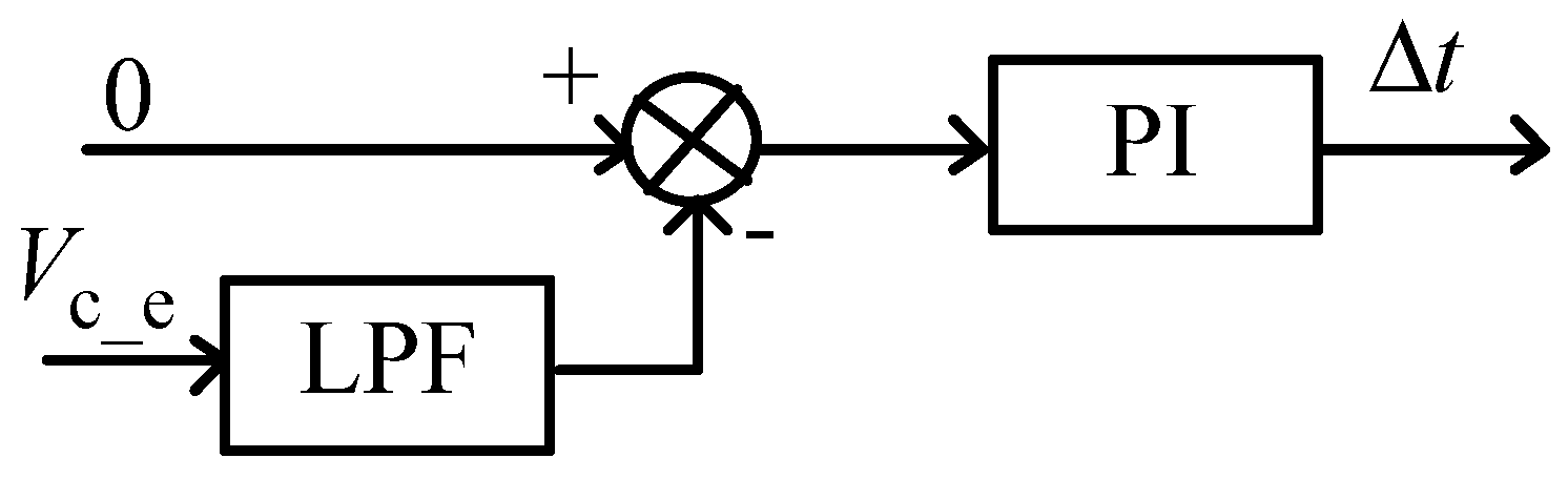
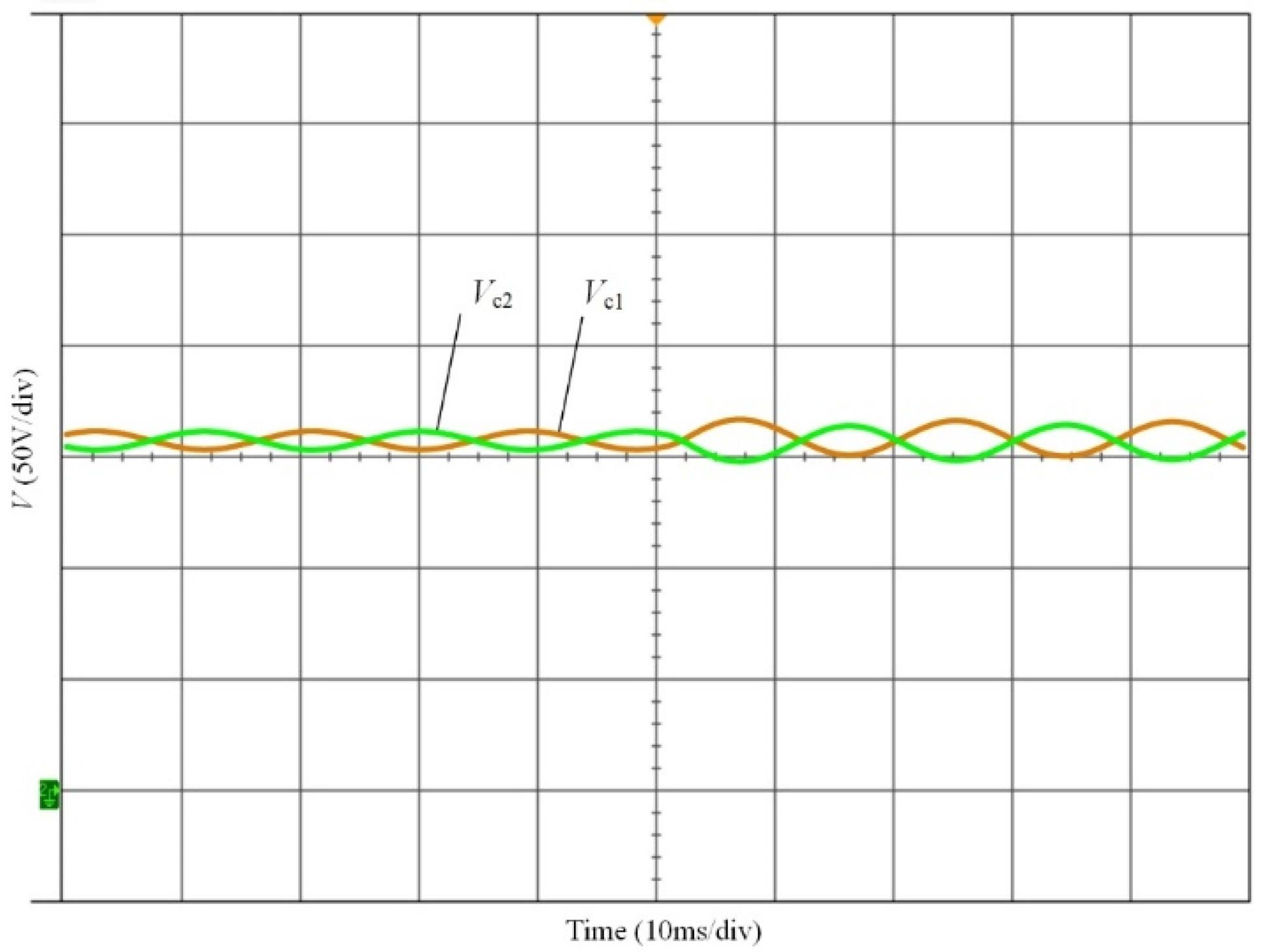
3.4. Capacitor Voltage Balance

It can be seen from (10) that the capacitor voltage balance can be realized by injecting a dc offset to ia. For the space vector V1 and V3, the output voltage of phase ‘a’ (Van) is 2/3Vc2 and −2/3Vc1, respectively. Thus, increasing the duration of V1 (t1) is equivalent to injecting a positive dc component into ia, and increasing the duration of V3 (t3) is equivalent to injecting a negative dc component into ia. According to Figure 5, an offset ( Δ t ), as given in (32), can be added to tb and tc to adjust the durations of V1 and V3:
{ t b = t b + Δ t t c = t c + Δ t .
If Δ t is positive, t1 is decreased and t3 is increased; it is equivalent to injecting a negative dc component into ia and it is helpful to decrease Vc_e. On the contrary, it is helpful to increase Vc_e if Δ t is negative. Accordingly, the control diagram of the capacitor voltage balance by adjusting Δ t can be designed as shown in Figure 7. The dc offset of Vc_e is obtained by a low pass filter (LPF), and a proportional integral (PI) controller is designed to make it 0.
The whole control diagram of the switching sequence MPDTC is shown in Figure 8. With the process of stator flux calculation under MTPA control as shown in the part A, the control objectives can be transferred to Ψ d * and Ψ q * from T e * and Ψ s * , which can avoid the complicated process of adjusting λ 1 , λ 2 in the conventional MPDTC. In addition, there is no need to design a cost function for the proposed capacitor voltage balance method, i.e., the design process of λ 3 in the conventional MPDTC can also be avoided. Thus, the problem of designing the weighting factors in the conventional MPDTC can be solved. Instead of selecting one space vector from V1V4 as shown in Figure 4, the switching sequence with three space vectors is selected for the proposed method. The switching frequency of the proposed switching sequence MPDTC is fixed and it is equal to the sampling frequency, which is helpful to decrease the torque and flux ripples.

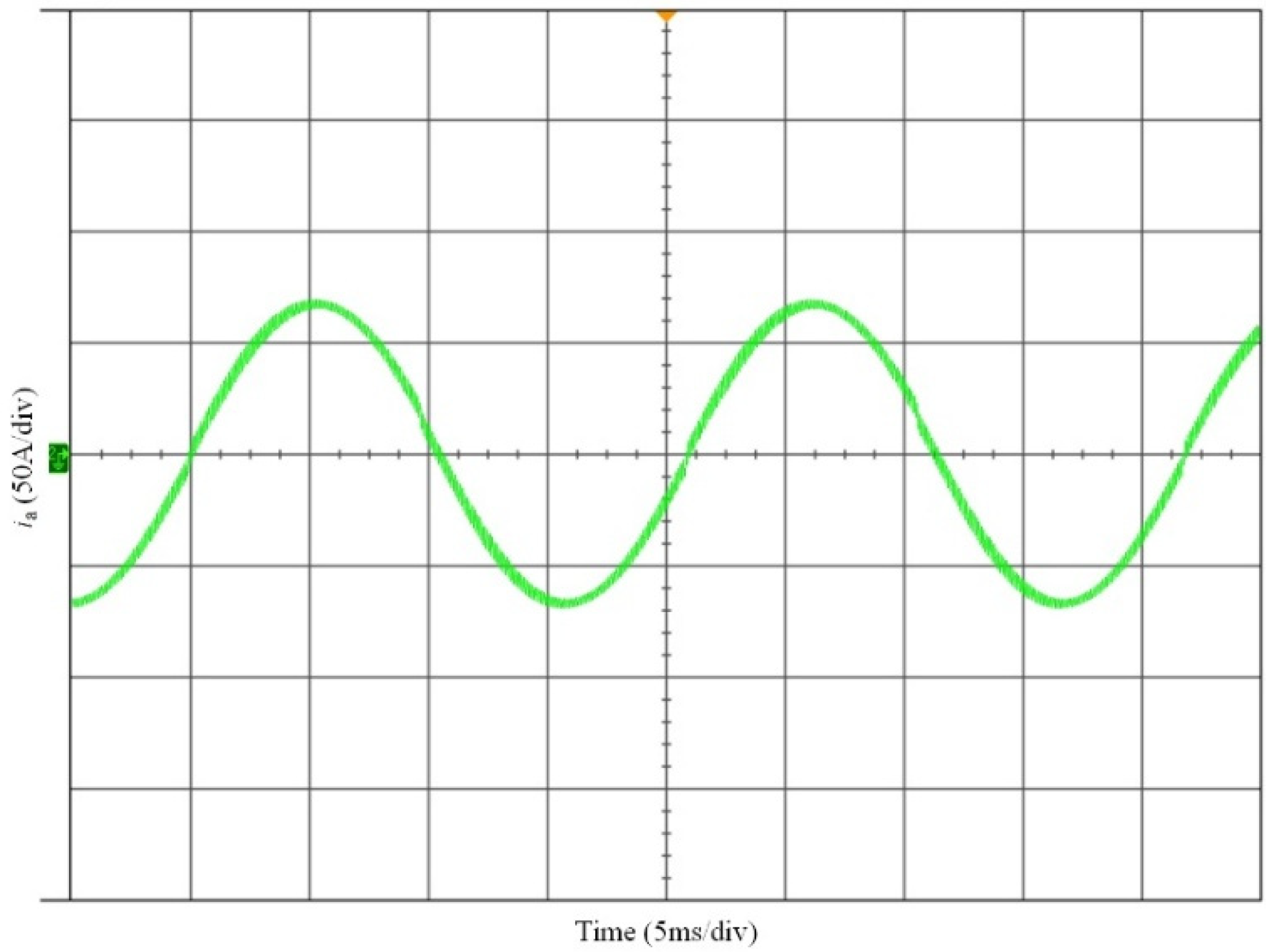
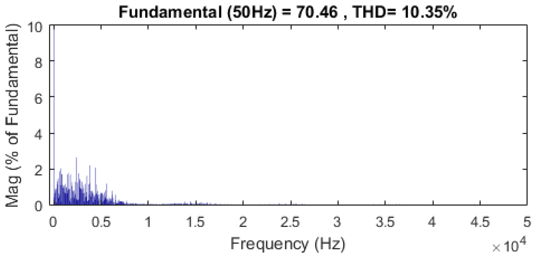
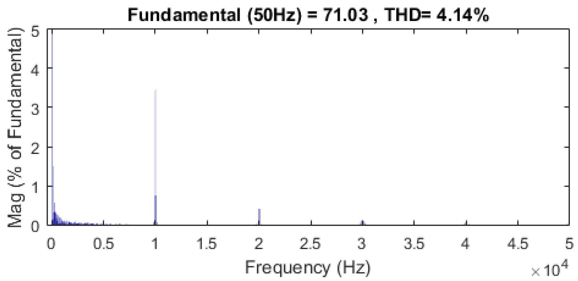
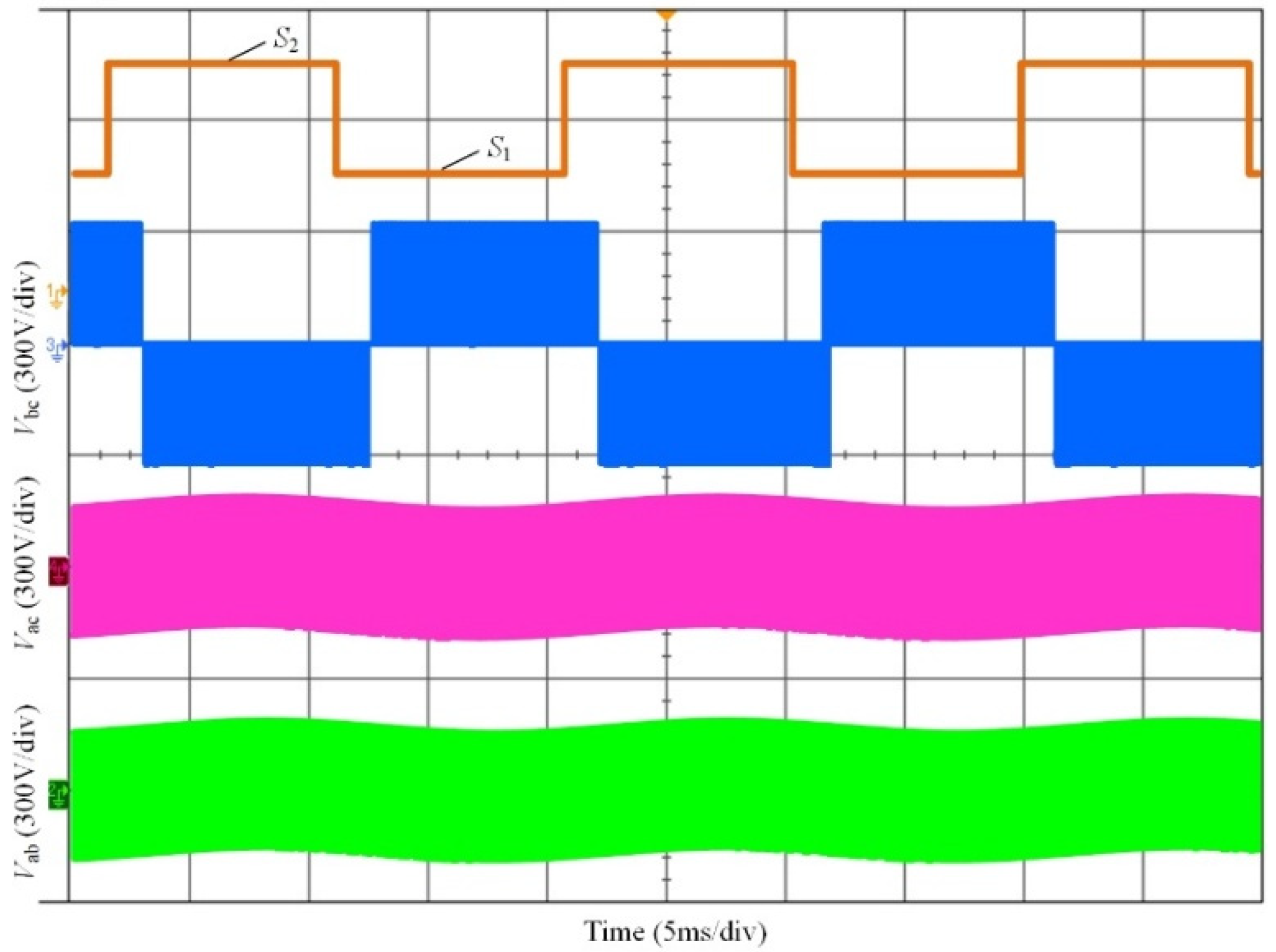
4. Experimental Results and Discussion

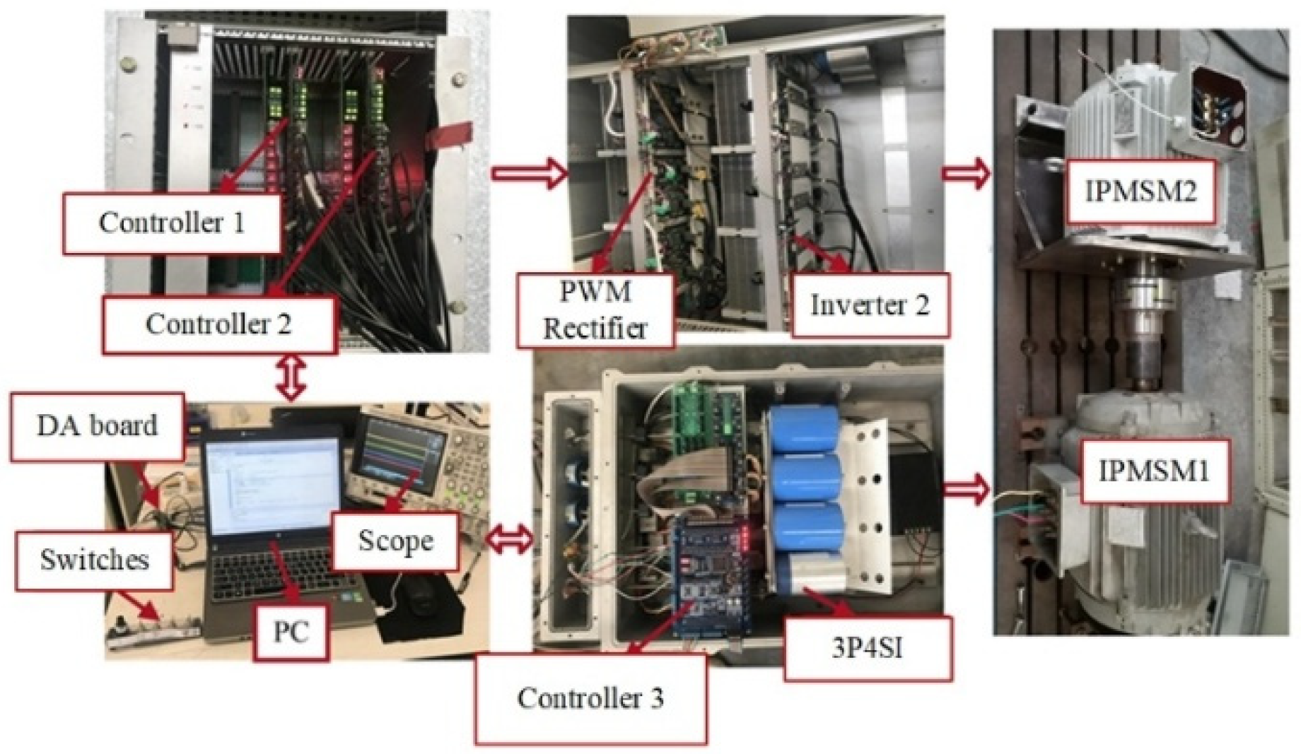
4.1. Experimental Prototype

To validate the effectiveness of the proposed switching sequence MPDTC of IPMSM for EV in switch-open fault-tolerant mode, an experimental setup as shown in Figure 9 was established. A 320 V dc-link voltage is obtained by the PWM rectifier controlled by the controller 1 to simulate the lithium battery packs. IPMSM1 and IPMSM2 are coaxially connected. IPMSM1 is connected with the 3P4SI, and the proposed control strategy is implemented by the controller 3. IPMSM2 is the load motor, which is fed by the inverter 2 with controller 2. The main parameters of the 3P4SI and IPMSM1 are given in Table 1.

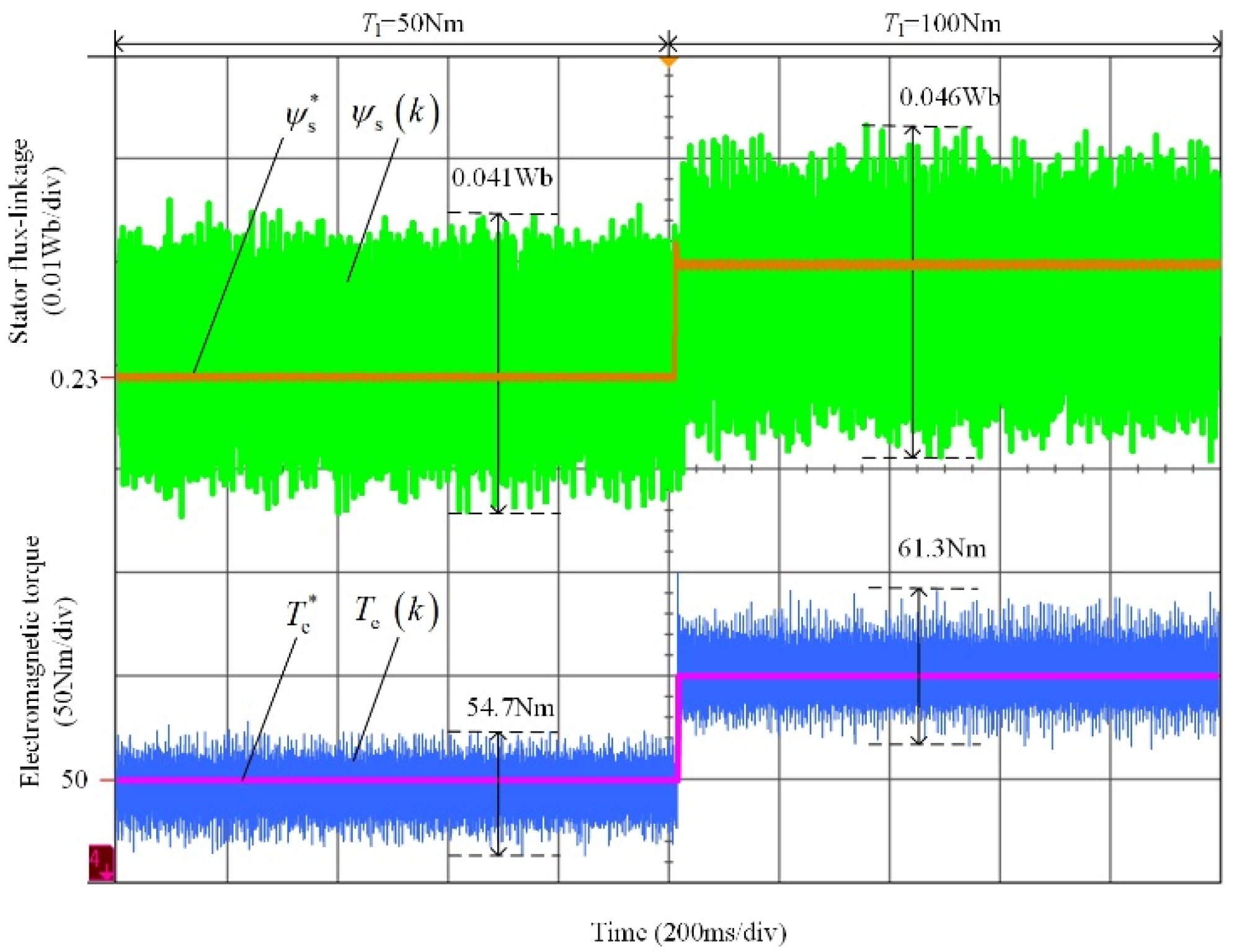
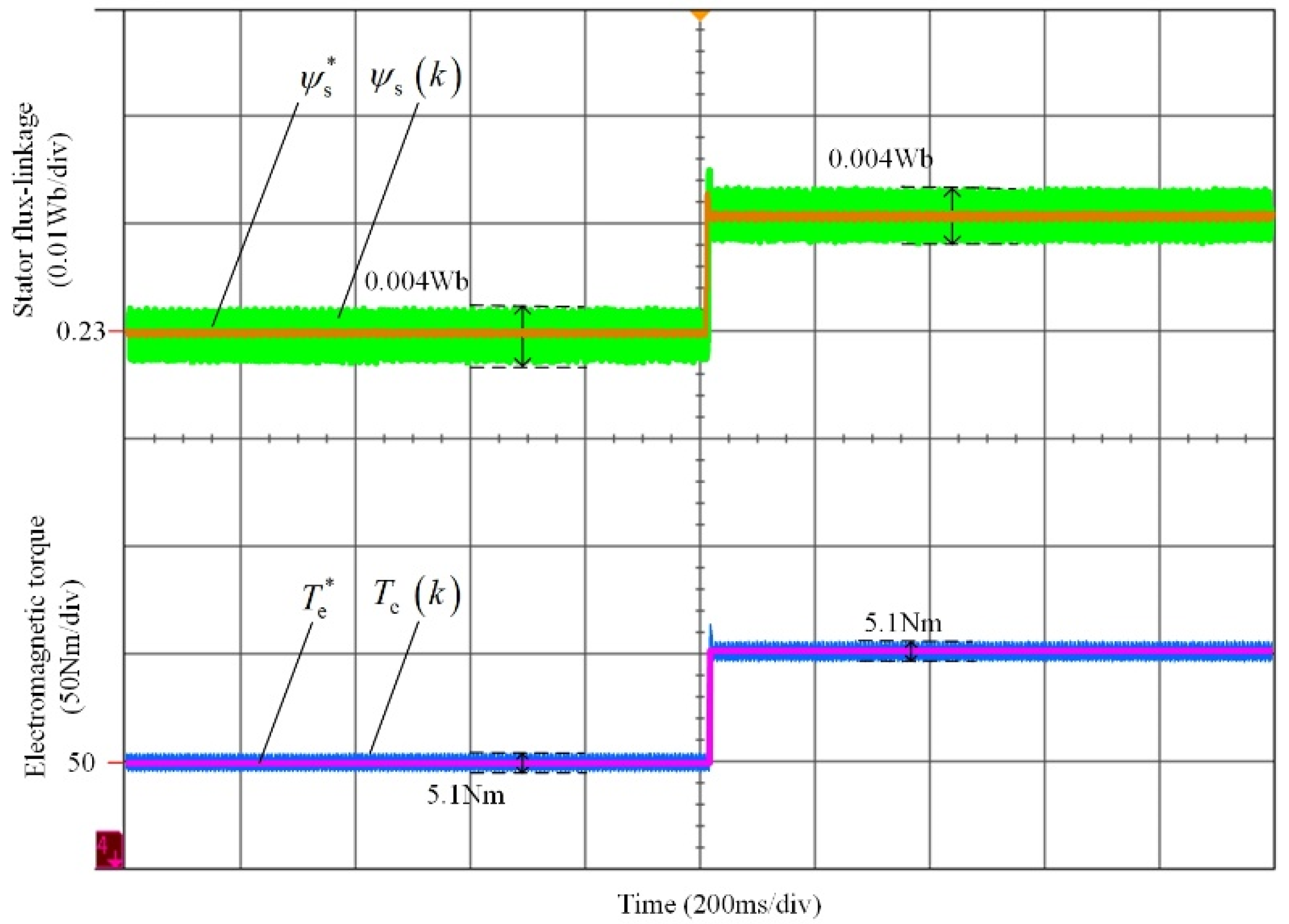
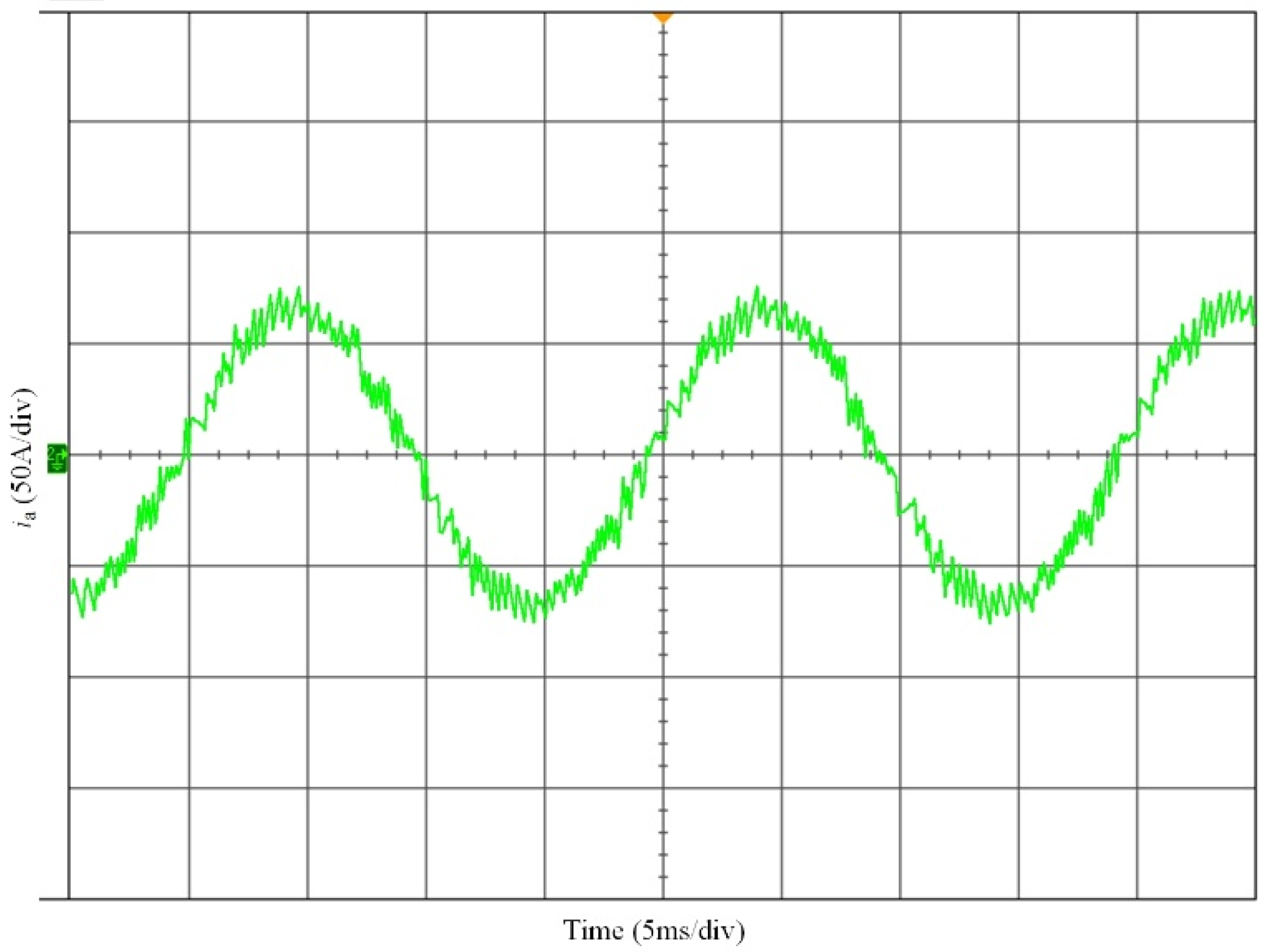
4.2. Results and Discussion

In the experiment, the speed of IPMSM1 is controlled as 750 r/min and the load torque (Tl) is set at 50 and 100 Nm at different periods. The curves of stator flux-linkage and electromagnetic torque for the conventional method as given in [22] and the proposed MPDTC are shown in Figure 10 and Figure 11, respectively. In the middle of Figure 10 and Figure 11, the load torque changes from 50 to 100 Nm. It can be seen from Figure 10 that the peak-to-peak values of the stator flux-linkage ripple for the conventional MPDTC are 0.041 and 0.046 Wb with Tl set at 50 and 100 Nm, respectively. With the proposed MPDTC, the stator flux-linkage ripple has been greatly reduced. As shown in Figure 11, the peak-to-peak values of the stator flux-linkage ripple for the proposed MPDTC are 0.004 and 0.004 Wb with Tl setting at 50 and 100 Nm, respectively. They were reduced by 90.2% and 91.3% in the two cases.
In addition, the peak-to-peak values of the electromagnetic torque ripple for the conventional MPDTC, as shown in Figure 10, are 54.7 and 61.3 Nm with Tl set at 50 and 100 Nm, respectively. With the proposed MPDTC, the electromagnetic torque ripple was also greatly reduced. As shown in Figure 11, the peak-to-peak values of the electromagnetic torque ripple for the proposed MPDTC are 5.1 and 5.1 Nm with Tl set at 50 and 100 Nm, respectively. They were reduced by 90.7% and 91.7% in the two cases. In addition, both the stator flux-linkage and electromagnetic torque can be fast tracked in the load sudden change case, and thus the proposed MPDTC has an excellent dynamic performance.
The curves of the phase current with Tl set at 100 Nm for the conventional and the proposed MPDTC are shown in Figure 12 and Figure 13, respectively. It is obvious that the current ripples were greatly reduced. The spectra of the phase current are shown in Figure 14 and Figure 15. For the conventional MPDTC, the total harmonic distortion (THD) of the phase current is 10.35%, and it was reduced to 4.14% with the proposed MPDTC method. As shown in Figure 14, the harmonic components of the phase current concentrate on the low frequency range, mainly owing to the switching frequency of the conventional MPDTC being far smaller than the sampling frequency and it is not fixed. On the contrary, the low frequency harmonic components as shown in Figure 15 were decreased, and the harmonic order concentrate on 200, which is equal to the switching frequency of the proposed MPDTC.
The curves of the sector and line-to-line voltage (Vab, Vac, Vbc) with Tl set at 100 Nm for the proposed MPDTC are shown in Figure 16. The line-to-line voltage curve between the two fault-free phases, i.e., Vbc as shown in Figure 16, is similar as the one of the 2L-VSI, while the line-to-line voltage curves between the fault-free and the fault phase were changed as Vac and Vab in Figure 16.
The curves of the capacitor voltages for the proposed MPDTC are shown in Figure 17. With the capacitor voltage balance control, both Vc1 and Vc2 are adjusted near 160 V.
Accordingly, the above analysis indicates that the proposed MPDTC method is effective. Compared with the conventional method, the ripples of the stator flux-linkage, electromagnetic torque, and phase current were greatly reduced with the same sampling period.

5. Conclusions

A switching sequence MPDTC of IPMSM for EV in switch open-circuit fault-tolerant mode was studied. The control objectives were transferred to Ψ d * and Ψ q * from T e * and Ψ s * under the MTPA control. Instead of selecting one space vector from the possible four space vectors, the proposed MPDTC method selects an optimized switching sequence including three space vectors and the calculation method of the durations of the adopted space vectors is given to realize the tracking of Ψ d * and Ψ q * . The capacitor voltage balance method, by injecting a dc offset to the current of the fault phase, is also given. The experimental results indicate the effectiveness of the proposed method and the electromagnetic torque ripples were decreased by more than 90% compared with the conventional method, which is helpful to maintain the driving comfort in the open-circuit fault-tolerant mode. In the future research, the smooth transition strategy from a healthy to open-circuit fault state with a model predictive controller will be investigated.

Author Contributions

T.Y. developed the switching sequence MPDTC control algorithms and performed the experiments and analyzed the data. S.H., T.K. and W.J. guided and revised the manuscript. All authors have read and agreed to the published version of the manuscript.

Funding

This research was funded by the 2019 Special Science and Technology Research Program of the Department of Education of Shaanxi grant number [19JK1005] and Yulin College School-level Teaching Reform Research Project grant number [JG1846].

Acknowledgments

The project is partially supported by the 2019 Special Science and Technology Research Program of the Department of Education of Shaanxi Province under award 19JK1005 and is partially supported by Yulin College School-level Teaching Reform Research Project under award JG1846.

Conflicts of Interest

The authors declare no conflict of interest.

References

  1. Hwang, M.-H.; Lee, H.-S.; Yang, S.-H.; Lee, G.-S.; Han, J.-H.; Kim, D.-H.; Kim, H.-W.; Cha, H.-R. Cogging Torque Reduction and Offset of Dual-Rotor Interior Permanent Magnet Motor in Electric Vehicle Traction Platforms. Energies 2019, 12, 1761. [Google Scholar] [CrossRef] [Green Version]
  2. Chen, J.; Chen, S.; Wu, X.; Tan, G.; Hao, J. A Super-Twisting Sliding-Mode Stator Flux Observer for Sensorless Direct Torque and Flux Control of IPMSM. Energies 2019, 12, 2564. [Google Scholar] [CrossRef] [Green Version]
  3. Wu, X.; Tan, G.; Ye, Z.; Liu, Y.; Xu, S. Optimized Common-Mode Voltage Reduction PWM for Three-Phase Voltage-Source Inverters. IEEE Trans. Power Electron. 2016, 31, 2959–2969. [Google Scholar] [CrossRef]
  4. De Pinto, S.; Camocardi, P.; Chatzikomis, C.; Sorniotti, A.; Bottiglione, F.; Mantriota, G.; Perlo, P. On the Comparison of 2- and 4-Wheel-Drive Electric Vehicle Layouts with Central Motors and Single- and 2-Speed Transmission Systems. Energies 2020, 13, 3328. [Google Scholar] [CrossRef]
  5. Mirafzal, B. Survey of Fault-Tolerance Techniques for Three-Phase Voltage Source Inverters. IEEE Trans. Ind. Electron. 2014, 61, 5192–5202. [Google Scholar] [CrossRef]
  6. Kersten, A.; Oberdieck, K.; Bubert, A.; Neubert, M.; Grunditz, E.A.; Thiringer, T.; De Doncker, R.W. Fault Detection and Localization for Limp Home Functionality of Three-Level NPC Inverters with Connected Neutral Point for Electric Vehicles. IEEE Trans. Transp. Electri. 2019, 5, 416–432. [Google Scholar] [CrossRef]
  7. Dehghanazad, E.; Gadoue, S.; Atkinson, D.J.; Slater, H.; Barrass, P.; Blaabjerg, F. Sensorless Control of IM Based on Stator-Voltage MRAS for Limp-Home EV Applications. IEEE Trans. Power Electron. 2018, 33, 1911–1921. [Google Scholar] [CrossRef]
  8. Zhou, X.; Sun, J.; Li, H.; Lu, M.; Zeng, F. PMSM Open-Phase Fault-Tolerant Control Strategy Based on Four-Leg Inverter. IEEE Trans. Power Electron. 2020, 35, 2799–2808. [Google Scholar] [CrossRef]
  9. Kivanc, O.; Ozturk, S. Low-Cost Position Sensorless Speed Control of PMSM Drive Using Four-Switch Inverter. Energies 2019, 12, 741. [Google Scholar] [CrossRef] [Green Version]
  10. Li, Z.; Wheeler, P.; Watson, A.; Costabeber, A.; Wang, B.; Ren, Y.; Ma, H. A Fast Diagnosis Method for Both IGBT Faults and Current Sensor Faults in Grid-Tied Three-Phase Inverters with Two Current Sensors. IEEE Trans. Power Electron. 2020, 35, 5267–5278. [Google Scholar] [CrossRef]
  11. Jlassi, I.; Cardoso, A.J.M. A Single Method for Multiple IGBT, Current, and Speed Sensor Faults Diagnosis in Regenerative PMSM Drives. IEEE J. Emerg. Sel. Top. Power Electron. 2020, 8, 2583–2599. [Google Scholar] [CrossRef]
  12. Zeng, Z.; Zhu, C.; Jin, X.; Shi, W.; Zhao, R. Hybrid Space Vector Modulation Strategy for Torque Ripple Minimization in Three-Phase Four-Switch Inverter-Fed PMSM Drives. IEEE Trans. Ind. Electron. 2017, 64, 2122–2134. [Google Scholar] [CrossRef]
  13. Fang, W.; Wang, Z.; Wang, D.; Li, R.; Li, M. A Strategy of Suppressing Torque Ripple in PMSM Drive System with Open-Phase Fault. In Proceedings of the 39th Chinese Control Conference, Shenyang, China, 27–29 July 2020; pp. 2573–2580. [Google Scholar]
  14. Lu, J.; Hu, Y.; Liu, J. Analysis and Compensation of Sampling Errors in TPFS IPMSM Drives With Single Current Sensor. IEEE Trans. Ind. Electron. 2019, 66, 3852–3855. [Google Scholar] [CrossRef]
  15. Hoang, K.D.; Zhu, Z.Q.; Foster, M.P. Influence and Compensation of Inverter Voltage Drop in Direct Torque-Controlled Four-Switch Three-Phase PM Brushless AC Drives. IEEE Trans. Power Electron. 2011, 26, 2343–2357. [Google Scholar] [CrossRef] [Green Version]
  16. Badsi, B.E.; Bouzidi, B.; Masmoudi, A. DTC Scheme for a Four-Switch Inverter-Fed Induction Motor Emulating the Six-Switch Inverter Operation. IEEE Trans. Power Electron. 2013, 28, 3528–3538. [Google Scholar] [CrossRef]
  17. Zhou, D.; Zhao, J.; Liu, Y. Predictive Torque Control Scheme for Three-Phase Four-Switch Inverter-Fed Induction Motor Drives with DC-Link Voltages Offset Suppression. IEEE Trans. Power Electron. 2015, 30, 3309–3318. [Google Scholar] [CrossRef]
  18. Rivera, M.; Yaramasu, V.; Llor, A.M.; Rodriguez, J.; Wu, B.; Fadel, M. Digital Predictive Current Control of a Three-Phase Four-Leg Inverter. IEEE Trans. Ind. Electron. 2013, 60, 4903–4912. [Google Scholar] [CrossRef]
  19. Zarei, M.E.; Ramirez, D.; Nicolas, C.V.; Arribas, J.R. Three-Phase Four-Switch Converter for SPMS Generators Based on Model Predictive Current Control for Wave Energy Applications. IEEE Trans. Power Electron. 2020, 35, 289–302. [Google Scholar] [CrossRef]
  20. Zarei, M.E.; Nicolas, C.V.; Arribas, J.R.; Ramirez, D. Four-Switch Three-Phase Operation of Grid-Side Converter of Doubly Fed Induction Generator With Three Vectors Predictive Direct Power Control Strategy. IEEE Trans. Ind. Electron. 2019, 66, 7741–7752. [Google Scholar] [CrossRef]
  21. Hua, W.; Huang, W.; Yu, F. Improved model-predictive-flux-control strategy for three-phase four-switch inverter-fed flux-reversal permanent magnet machine drives. IET Electr. Power Appl. 2017, 11, 717–728. [Google Scholar] [CrossRef]
  22. Sun, D.; Su, J.; Sun, C.; Nian, H. A Simplified MPFC With Capacitor Voltage Offset Suppression for the Four-Switch Three-Phase Inverter-Fed PMSM Drive. IEEE Trans. Ind. Electron. 2019, 66, 7633–7642. [Google Scholar] [CrossRef]
Figure 1. Speed regulation system of EVs on the basis of IPMSMs (a) 2L-VSI (b) 3P4SI.
Energies 13 05593 g001
Figure 2. Space vector diagrams. (a) In normal mode. (b) In switch-open fault-tolerant mode.
Energies 13 05593 g002
Figure 3. MTPA and the fitting curve.
Energies 13 05593 g003
Figure 4. Space vector diagram for 3P4SI. (a) Vc1 = Vc2 (b) Vc1 < Vc2 (c) Vc1 > Vc2.
Energies 13 05593 g004
Figure 5. Switching sequence diagram (a) Switching sequence I (b) Switching sequence II.
Energies 13 05593 g005
Figure 6. Trajectory of (a) Ψ d and (b) Ψ q with the switching sequence I.
Energies 13 05593 g006
Figure 7. Diagram of capacitor voltage balancing strategy.
Energies 13 05593 g007
Figure 8. Control diagram of the switching sequence MPDTC.
Energies 13 05593 g008
Figure 9. Experimental setup.
Energies 13 05593 g009
Figure 10. The curves of stator flux-linkage and electromagnetic torque for the conventional MPDTC.
Energies 13 05593 g010
Figure 11. The curves of stator flux-linkage and electromagnetic torque for the proposed MPDTC.
Energies 13 05593 g011
Figure 12. The curve of phase current for the conventional MPDTC.
Energies 13 05593 g012
Figure 13. The curve of phase current for the proposed MPDTC.
Energies 13 05593 g013
Figure 14. Spectrum of the phase current for the conventional MPDTC.
Energies 13 05593 g014
Figure 15. Spectrum of the phase current for the proposed MPDTC.
Energies 13 05593 g015
Figure 16. The curves of the sector and line-to-line voltage for the proposed MPDTC.
Energies 13 05593 g016
Figure 17. Curves of the capacitor voltages for the proposed MPDTC.
Energies 13 05593 g017
Table 1. Parameters of the IPMSM.
ParameterValue
Vdc320 V
C1,C24 mF
ψ f 0.21 Wb
Ld/Lq0.94/2.1 mH
R0.08 Ω
Pole Pairs4
Ts0.0001 s
Imax100 A
Publisher’s Note: MDPI stays neutral with regard to jurisdictional claims in published maps and institutional affiliations.

