1. Introduction
Line start permanent magnet synchronous motors (LSPMSM) are increasingly used in electric drives without a speed control instead of squirrel cage induction motors. This is due to the fact that, among other reasons, these motors obtain higher power densities, efficiency and power factor than induction motors with the same power [
1,
2,
3,
4]. As a result, widespread use of LSPMSMs allows one to achieve a significant reduction in the cost of electricity consumed, especially in drives operating continuously. Additionally, due to the increase of the power factor, the reactive power balance in the power systems supplying these motors is improving. For the above reasons, it is advisable to use such motors, for example, to drive pumps and fans in mines. The widespread use of this type of motor will help to reduce greenhouse gas emissions.
LSPMSMs are designed for direct start-up as well as for constant rotational speed operation. Expensive power electronics systems enabling starting and regulation of motor speed do not have to be used in this type of drive. As a result, the price decreases and the reliability of the drive increases.
An LSPMSM is equipped with two windings: a three-phase winding in the stator slots, and a cage winding in the rotor [
1,
2,
4,
5,
6,
7,
8]. The cage winding is used to start the motor. During a direct start of the motor, the stator winding is connected to a three-phase voltage source. It induces a rotating field in the machine, and the asynchronous electromagnetic torque generated by the cage winding causes the motor to start. The asynchronous torque disappears at the rotor speed equal to the rotation speed of the magnetic field created by the stator winding.
During the asynchronous starting process, currents with a maximum value up to several times greater than the amplitude of the rated motor current can flow in the stator winding [
8,
9]. Supply voltage, the magnetic flux generated by magnets, the moment of inertia of rotating masses and load torque affect the start-up course and the amplitude of the inrush current [
8,
9]. The impact of the magnetomotive force caused by the armature interaction related to the amplitude of the stator currents may cause partial demagnetization of the permanent magnets located in the motor [
9]. This situation can occur in machines with an improperly designed electromagnetic circuit. Due to the partial demagnetization of the magnets, the main magnetic flux in the machine is irreversibly reduced. This diminishes the generated electromagnetic torque, and thus the motor power [
5].
It should be emphasized that magnets can accumulate negative outcomes of impact effects of armature magnetomotive force, if it occurs often [
10]. This situation may happen, among others, in frequently repeated starting processes. If during one of the start-ups the magnets are partially demagnetized, the next start of the motor will take place at a lower main magnetic flux. This can increase the inrush current amplitude and further demagnetize the magnets. Therefore, it is desirable to design the motor in such a way that the effect of the repeated partial demagnetization process serves to stabilize the flux generated by the permanent magnets. It should be pointed out that the motor operation with the magnetic flux smaller than the rated one causes an increase in current, power loss, and raises the temperature in magnets, which, in effect, further reduces the main flux of the machine.
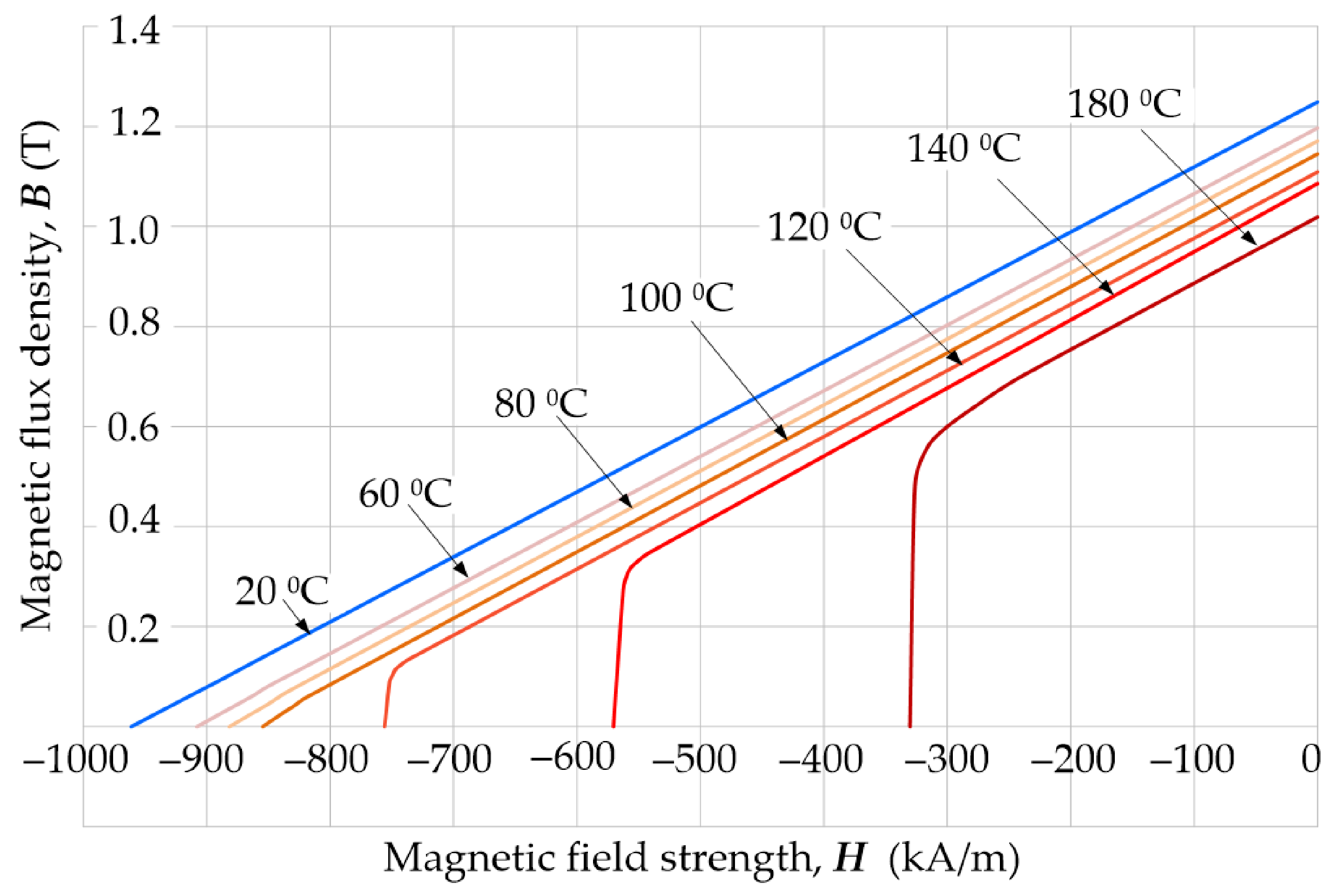
The susceptibility of magnets to partial demagnetization increases with the rise of temperature. In catalogs of magnetically hard materials, the influence of temperature
τ on magnetic properties of magnets is most often presented using a family of demagnetization characteristics—see
Figure 1.
The temperature of motor components and permanent magnets depends on the power losses emitted in the machine. It also depends on the ambient temperature and the ability to transfer heat from the machine to the environment. Several heat sources can be identified in the motor. These are the power losses emitted in the windings, stator and rotor core and in bearings [
11]. Eddy currents induced in solid conductive elements are also the sources of the power losses, e.g., permanent magnets. Large increases in temperature of the magnets can be observed at frequently repeated heavy starting processes of the motor or its reversals carried out at high values of load and the moment of inertia of rotating masses. The thermal exposure occurring during the prolonged operation of the machine in an environment with elevated temperature is particularly dangerous for the magnets. The accumulation of adverse thermal exposures can cause a decrease in the magnet’s resistance to demagnetization and, as a consequence, partial demagnetization of permanent magnets due to the impact of armature magnetomotive force. It should be emphasized that the process of partial demagnetization of the magnets is irreversible and causes permanent deterioration of functional parameters of the motor [
2,
11,
12]. For the above reasons, in order to analyze this process, electromagnetic and thermal phenomena should be considered at the same time in connection with the dynamics of the machine’s moving elements.
For practical reasons, the issue of partial demagnetization of permanent magnets in electric motors is still current and has been discussed in a number of publications for many years. Several lines of research can be distinguished in studies presented in the literature. They concern, among others, experimental research on the behavior of magnets subjected to external demagnetizing fields [
13,
14,
15]. For the analysis of the irreversible demagnetization process, models of phenomena of varying complexity are proposed. Most of them are based on the magnetization characteristic of magnets [
13,
16,
17], and in the papers [
13,
18] the influence of temperature on the magnetic behavior in the external magnetic field is additionally taken into account. In the most complex aspects, magnetic hysteresis models [
10,
19,
20] are used to map the partial demagnetization of magnets. However, for the determination of magnetic fields that demagnetize magnets in electric machines, both models, based on simplified substitute schemes [
15,
21] and the finite element method [
16,
17,
22], are used. In [
23,
24], a combination of numerical integration of machine equations and the finite-element method is used to study the irreversible demagnetization process. These types of aspect were used to analyze the process of partial demagnetization of magnets, including LSPMSM start-up [
22,
25], short circuits in the motor’s electrical circuits [
26,
27], the motor falling out of synchronism [
9,
23,
27], and when seeking structural solutions limiting the partial demagnetization of magnets [
18,
22]. Studies described in the literature mostly present analyses of the partial demagnetization process carried out for the set temperature of magnets [
13,
18]. In Refs. [
28,
29], a simplified, thermal substitute diagram of a motor was used to determine the temperature of the machine’s components. There is relatively little work on the comprehensive field analysis of compressed electromagnetic-thermal phenomena including the irreversible process of partial demagnetization of magnets [
2,
6]. The comprehensive models allow the analysis of the dynamic state of the machine, taking into account both the process of partial demagnetization of magnets and the effect of temperature on the magnetic, electrical and thermal properties of materials.
The authors, due to the lack of commercial software enabling the analysis of the simultaneous effect of stator current and temperature during motor dynamics on the process of partial demagnetization of permanent magnets, have attempted to develop a field model of coupled electromagnetic-thermal phenomena in an LSPMSM. Based on the algorithm for solving equations of the model presented in the paper, the authors developed special software. The software was used to analyze the simultaneous impact of armature current and temperature during motor dynamics on the process of partial demagnetization of permanent magnets. The simulation and experimental studies were limited to testing this process during the direct start-up of the permanent magnet synchronous motor. The research aimed to confirm the usefulness of the developed software for the mentioned above objective.
2. Mathematical Model of Line Start Permanent Magnet Synchronous Motors (LSPMSM)
The mathematical model of transient coupled phenomena in an LSPMSM includes equations describing the distribution of the magnetic field, currents in the windings, temperature distribution and the equation for dynamics of mobile elements in the drive system.
It has been assumed that in the electromagnetically active region of the motor, magnetic and thermal fields are two-dimensional [
2,
6]. Based on the above, the distribution of the transient magnetic field can be described by a system of equations [
11].
where
ν is the magnetic reluctivity of the domain,
A is the magnetic vector potential,
J is the current density vector,
σ is the conductivity of the medium
Jm is the current density vector representing the magnetization of the permanent magnet that depends on the magnetization vector in the region with the permanent magnets
M,
V is the electric scalar potential,
B is the vector of magnetic flux density.
In the developed model of phenomena, the reluctivity of soft magnetic material and permanent magnetization are determined according to the following relationship [
2]:
where:
H is the magnetic field strength vector,
νo is the reluctivity of the vacuum.
When calculating the reluctivity from relationship (5), the magnetizing characteristic of soft magnetic material is used. However, when modeling the properties of magnetically hard material, it is assumed that it is characterized by rectangular magnetic anisotropy [
12]. For each elemental volume of the magnet, a local coordinate system with orthogonal axes α,
β is introduced and it is assumed that the α axis coincides with the direction of the magnetization vector
M.
The magnetization of the magnet in the α direction depends on the intensity
H of the external magnetic field and on the temperature as well as being calculated from the family of
B(
H,
τ) demagnetization characteristics of magnets. An exemplary family of such characteristics for the N38SH material is shown in
Figure 1. However, in the
β direction it is assumed that the magnetization vector component is equal to zero.
To determine the magnetization from the
B(
H,
τ) demagnetization characteristic, the following model of partial demagnetization of the magnet has been proposed. It is based on the well-known behavior of magnetically hard material in the external magnetic field [
30].
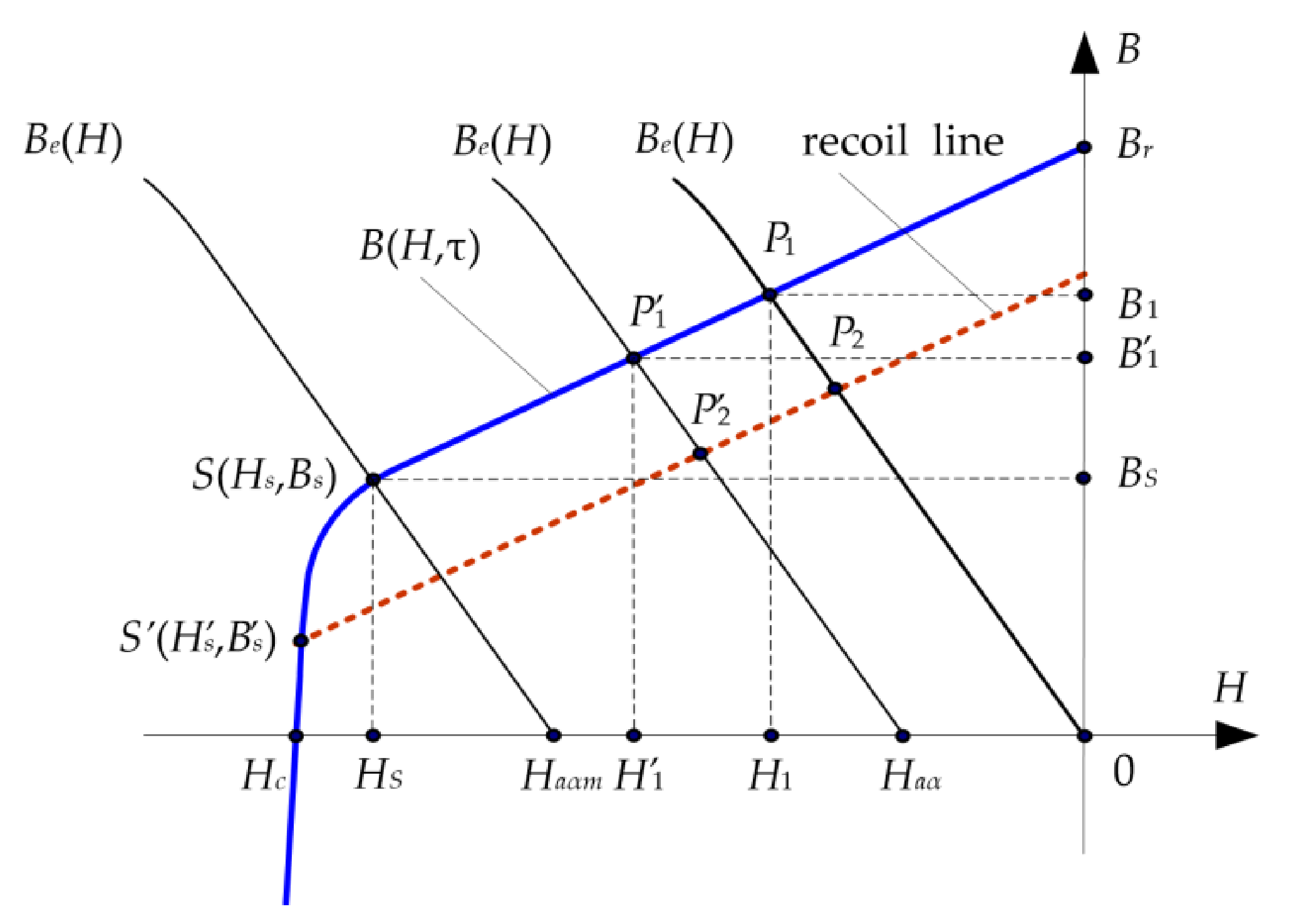
In order to explain the functioning of the model, it has been assumed that the work point of the elemental volume of the magnet lies on the linear part of the demagnetization characteristic
B(
H,
τ) [
30]. In particular, with the absence of current in the armature winding, the operating point
lies at the intersection of the
B(
H,
τ) characteristic and the
(
H) characteristic of magnetization of the external magnetic circuit with respect to the considered elemental volume of the magnet (
Figure 2).
During the machine operation, currents in the stator winding cause the magnetic field
in the magnet. The
component of the
field with the opposite turn to the magnetization vector
M acting in the direction of the
α axis, causes the work point
to shift to the left on the
B(
H,
τ) characteristic. As a result, the magnetic flux density from
to
B1’ and thus the magnetic flux produced by the permanent magnet decrease. When the armature field disappears, the flux density in the magnet again becomes
. If the field amplitude
(where
< 0,
< 0), then the work point will not move below the
S point and the armature field will not partially demagnetize the considered magnet volume (point
S is on the linear part of the characteristic
B(
H,
τ)). The irreversible, partial demagnetization of the magnet will occur if
<
. Then point
S will move along the bend, down the demagnetization characteristic, e.g., to point
S’, and the new magnet work point
will then lie on the recoil line, marked as a dashed line in
Figure 2. Changing the position of the starting point
S of the recoil line on the demagnetization characteristic is called the magnet stabilization process. The presented process of the magnet stabilization is caused by the impact field of the armature. After the stabilization process, the flux density and field strength in the magnet depend on the location of the point
S’ on the
B(
H,
τ) demagnetization characteristic and on the slope of the recoil line relative to the abscissa. The slope of the recoil line for neodymium magnets practically coincides with the slope of the straight portion of the demagnetization characteristic.
The current density
J from Equation (2) that appears in the winding area is not known in advance. For this reason, the Kirchhoff equations for electric circuits of the motor and the power supply system must be included in the phenomena model:
where:
U is the vector of supply voltages,
R and
L represent the matrix of loop resistances and the matrix of end-turn inductances, respectively,
i is the vector of loop currents,
Φ is the flux linkage vector calculated.
The components of the current vector
i depend on the current density distribution
J in the conductors and, for example, the current
ik for the
k-th conductor is:
where
Sk is the cross-sectional area of the
k-th conductor.
In the model of electromagnetic phenomena, the three-dimensionality of the field in the area of winding front connections was taken into account in an approximate way by introducing lumped parameters, mapping the resistance and inductance of these connections into Equation (7).
In order to model transient states of the synchronous motor, Equations (1)–(6), describing the slowly varying magnetic field and Equation (7), describing the currents in the electrical circuits, are solved simultaneously with the mechanical equilibrium equation of the drive system [
2,
6,
31].
where:
is the moment of inertia of rotating masses,
ω = d
α/d
t is the angular velocity,
α is the angular position of the rotor,
is the friction torque,
is the load torque,
is the driving torque.
In the presented model of electromagnetic phenomena, the torque
is determined on the basis of magnetic field distribution [
31].
As mentioned in section I, during motor operation, power losses are generated in its windings, ferromagnetic core, solid conductive elements and bearings. They increase the temperature of the motor components. As the temperature changes, the electrical, magnetic and thermal properties of the materials that form the machine also change. The altered properties of the materials affect the course of electromagnetic and thermal processes in the machine. Due to the presented coupled phenomena in the mathematical model, the equation describing thermal phenomena in the motor is also taken into account [
2,
6]
where:
λ is the tensor of thermal conductivity,
Q is the power loss density,
τ is the temperature,
c is the specific heat and
ρ is the specific mass.
When calculating the power loss density in windings and permanent magnets, it is assumed that
Q = |
J|
2/
ρ, whereas, power losses in the core composed of magnetic sheets are caused by the hysteresis phenomenon and eddy currents induced in the sheets. It has been assumed that they are determined in a classic way on the basis of sheet loss and magnetic flux density distribution [
2].
The process of modeling the boundary conditions for Equation (10) assumed that the heat flux
qN penetrating the machine’s edge surface and entering the environment is equal to the heat flux transmitted to the environment by convection:
where:
N is the normal direction in relation to the edge surface,
is the bulk temperature of the fluid,
is the ambient temperature,
κ is the heat transfer coefficient.
In order to calculate the temperature on the housing of the motor cooled with an air stream, the substitute coefficient of the heat transfer in (11) was calculated as:
where
is the natural thermal convection coefficient,
v is the linear velocity of air,
is the coefficient characterized by the cooling intensity.
As is well known, the both conductive and convective heat transfers occur in the air gap between the rotor and the stator [
32]. Therefore, an effective thermal conductivity must be determined, which includes both conduction and convection in the air gap. In order to calculate the convective heat coefficients considering the state of the air flow in the air gap, the authors used the method proposed in [
33]. The solution of Equation (10) is unambiguously determined by the boundary conditions (11) and initial conditions [
29,
34].
To solve Equations (1), (7), (9) and (10) of the presented model of coupled electromagnetic and thermal phenomena in an LSPMSM, numerical methods based on space and time discretization were used [
2,
6,
12,
29,
35]. The model of coupled phenomena can be written as a system of non-linear algebraic equations [
2,
5], after space discretization, application of the finite element method and using the step-by-step algorithm:
where:
S is the magnetic reluctance matrix,
φ is the vector of the potential in nodes of the mesh,
C is the matrix of coefficients,
z is the matrix describing the number of turns assigned to the mesh nodes,
G is the matrix of equivalent electrical conductances,
fm is the vector representing the magnetization of the permanent magnets,
is the matrix of thermal conductances,
represent the matrices of thermal capacitances,
τ is the vector of unknown temperatures,
KτS and
KτA are the matrices of the coefficient describing heat transfer transport to the ambience of the motor.
is the time-step length,
n and
n − 1 denote the quantities of the current
and the previous (
t =
tn-1) time-step number.
It should be emphasized that in the presented numerical model of transient electromagnetic-thermal phenomena, the elements of the
G, R, Sτ matrices and the
fm and
Q vectors depend on temperature [
2,
5,
35]. When determining the elements of the
fm vector that map the magnetization of the magnets, the
B(
H,
τ) series of the demagnetization characteristic (
Figure 1) and principles of interpolation of the magnetic flux density
B with respect to the magnetic field strength
H and temperature
τ are used.
For the mapping of the rotor’s movement in a discrete model of coupled phenomena, the distorted element and the remeshed band method was used [
31]. However, the electromagnetic torque
in Equation (15) is calculated on the basis of the potential distribution of the grid nodes
using the Maxwell stress tensor formula [
11,
31].
To solve the non-linear Equations (13)–(15) of the discrete model of electromagnetic and thermal phenomena in an LSPMSM, the authors used the Newton–Raphson procedure coupled with the block-over relaxation method. The developed algorithm for solving equations assumes that the calculation blocks correspond to Equations (13) and (14) of the discrete model of phenomena, respectively. In order to reduce the calculation time, due to the much lower dynamics of thermal phenomena in relation to electromechanical phenomena, the authors used the cascade approach of selecting the time-step length [
33].
It should be emphasized that the advantage of the presented algorithm for the analysis of coupled electromagnetic and thermal phenomena is that it takes into account the influence of temperature and the process of partial demagnetization of magnets on the course of LSPMSM dynamic states. Such a possibility is not available in commercially available software packages for analysis of coupled phenomena in machines excited by permanent magnets.
On the basis of the presented algorithm for solving the equations of the discrete model of coupled phenomena, the authors developed their own software for analyzing the influence of temperature and impact current of a stator on the partial demagnetization of LSPMSM excitation magnets. It was written in the Delphi programming environment, implemented for calculations on a PC.
3. Results
The software was used to analyze the effect of temperature on the LSPMSM behavior in dynamic and steady-state operating conditions. The structure of the considered LSPMSM is shown in
Figure 3.
The motor has 36 drop-shaped slots in the stator, and the rotor has a copper starting cage with 28 round bars. The excitation flux is produced by N38SH neodymium magnets arranged in a
U-shape on the pole pitch of the rotor core [
2]. The stator phase winding is adapted for 400 V power supply and connected in a star configuration. The motor parameters are summarized in
Table 1.
In the developed discrete 2D model of the LSPMSM, the numbers of the calculated potentials φ and temperatures of the τ mesh nodes stand at about 37,000 and 40,000, respectively. Test calculations carried out on a PC with an Intel CORE i7 processor show that for a time step length of ∆t = 0.0001 s the calculation time for one supply voltage period was about 6 min.
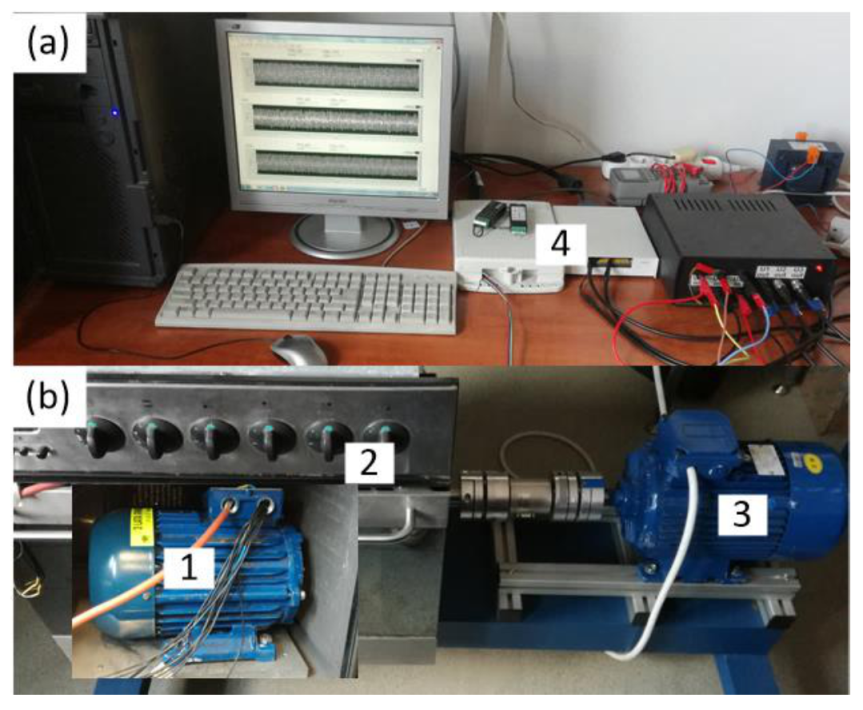
The states of generator and motor machine operation were considered. In order to confirm the credibility of the simulation tests, a comparison of the results of calculations to the results of experimental tests was made. The experimental tests were carried out on a specially designed and constructed test stand,
Figure 4. The tested motor (1) was placed in a thermal chamber (2) which enabled the temperature to be set from ambient to 250 °C. Depending on the type of work, the tested LSPMSM was coupled with a three-phase propulsion motor (3) (during generator operation of the machine) or a magnetorheological brake (4) (during motor operation). The advantage of the brake used is the lack of pulsation of its anti-torque. To measure the temperature of coils belonging to different phase windings, authors used PT-100 temperature sensors. These sensors are located along the circumference of the stator core, in the middle of the length of the slots, next to their openings near the winding surface. SCC-RTD01 modules from the National Instruments (NI) Corporation (5) and an application developed in the LabView environment were used to measure and record voltage, current, temperature and rotational speed [
33]. The torque on the motor shaft was measured with a torque transducer (6).
Before starting the calculations, the calibration procedure used in the author’s software of the discrete two-dimensional model of thermal phenomena was carried out. The calibration consisted in such selection of the value of the equivalent coefficient of heat transfer from the motor to the environment described by the relation (11), for which the best compliance of the calculation results with the results of the experimental tests of the motor heating process was obtained. Details of the tuning process of the applied thermal model are discussed in [
33].
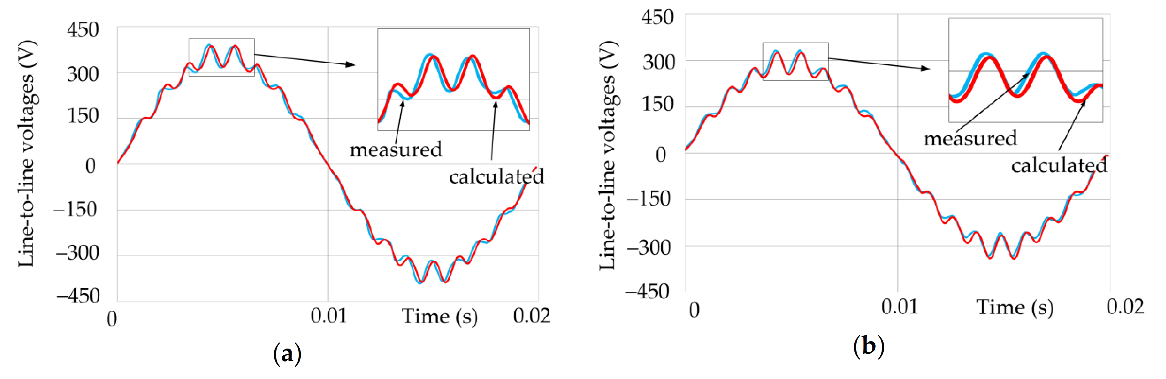
First, the effect of temperature on the waveform and root mean square (RMS) value of the electromotive force e(t) induced in the windings of the machine operating at no-load as a generator was analyzed. The tests were carried out for the thermally steady state at the rotation speed of the rotor equal to synchronous speed = 1500 rpm. When measuring the induced voltage waveforms e(t) on the test bench, for fear of exceeding the permissible operating temperature of the magnets, it was limited to operating the machine in the temperature range τ from 26 °C to 140 °C. The same machine operating conditions were reproduced in the simulation tests.
It should be emphasized that the induced voltage tests were carried out immediately after installing magnetized permanent magnets in the motor. Thus, the magnets were not exposed to demagnetization before the machine tests, due to the high temperature and the impact magnetomotive force of the armature.
The measured, line-to-line voltage
eL1-L2 waveforms for given machine component temperatures equal to
τ = 26 °C and
τ = 140 °C, are shown in
Figure 5a,b. Because the other line-to-line voltages differed only in their phase displacement, their waveforms were not included in the paper. The figures also show the voltage waveforms obtained from the calculations. RMS values of the induced voltages are summarized in
Table 2. The table also gives the values of the coefficient
determining the discrepancy between the results of the calculations and measurements:
where
and
are the effective values of the voltages
e(
t) obtained from the measurements and calculations, respectively. The table shows that the relative percentage difference between the results of the calculations and measurements does not exceed 3.80%.
The obtained results of the measurements and simulations confirm that the value of induced voltage decreases with increasing temperature. It can also be seen that the temperature has little effect on the shape of voltage waveforms.
Repeated measurements of the electromotive force after the machine had cooled to ambient temperature confirmed that the tests carried out at elevated temperature did not affect the voltage induced in the windings, and thus the magnetization state of the magnets.
According to the authors, the differences between the measurement results and calculation results were caused, among other factors, by: (a) the assumption of a two-dimensional field in the machine, (b) the accuracy of the measurements, (c) discrepancies between the catalog calculations and actual magnetic properties of the materials used, (d) the inaccuracy of circuit components of the electromagnetic motor, (e) errors of the applied method resulting from the assumed density of space and time discretization as well as the assumed accuracy when solving the equations of the discrete model.
In order to further verify the developed algorithm for analyzing phenomena and the computer software as well as to examine the simultaneous effect of armature magnetomotive force (
MMF) and temperature on the work of the motor and magnetization state of the magnets, simulation and experimental tests of the motor starting process were carried out. Direct motor start-ups were repeated for given values of the load torque
, initial temperature τ and machine components. The set values of the load torque
and temperature
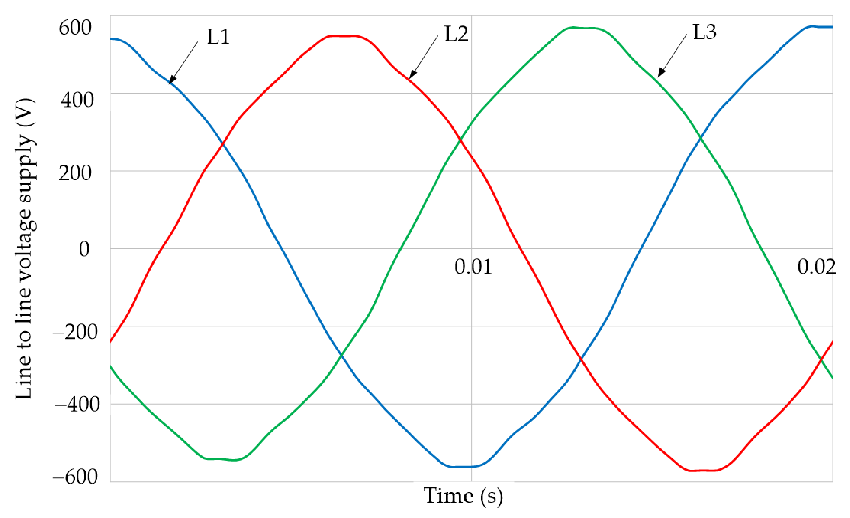
were {0, 9.5, 14.5, 19.5} Nm and {26, 40, 60, 80, 100} °C, respectively. The motor was supplied directly from the power grid. An example of the supply voltage waveform measured at the test stand is shown in
Figure 6. It follows that the waveforms of line-to-line voltages are deformed compared to the sinusoidal waveforms. In addition, as is known, the course of the LSPMSM start-up process depends both on the angular position of the rotor relative to the stator and on the voltage phase at the time the motor windings are connected to the power grid [
22]. For these reasons, the calculations assumed that for each of the start-ups the motor was supplied with voltage of such a course and phase as was measured on the test stand. In addition, the same rotor’s angular position relative to the stator was set before each motor start-up. The obtained results of the simulation calculations were compared to the results of the experimental studies.
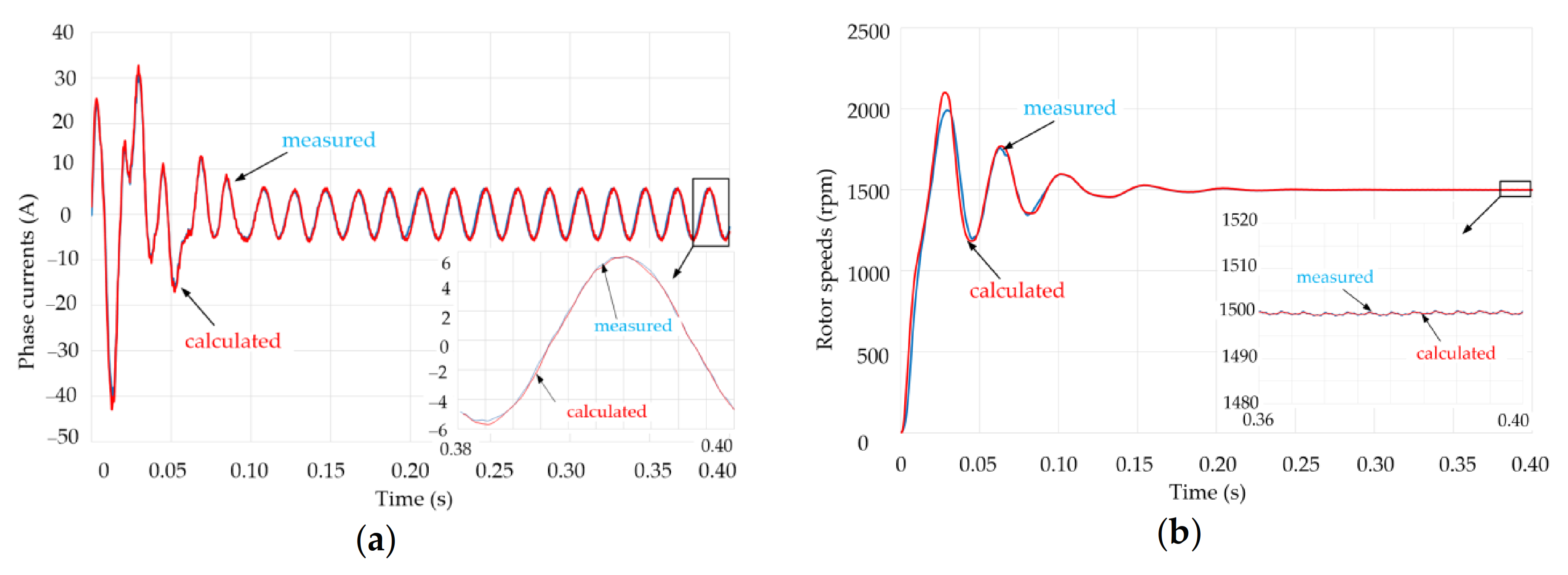
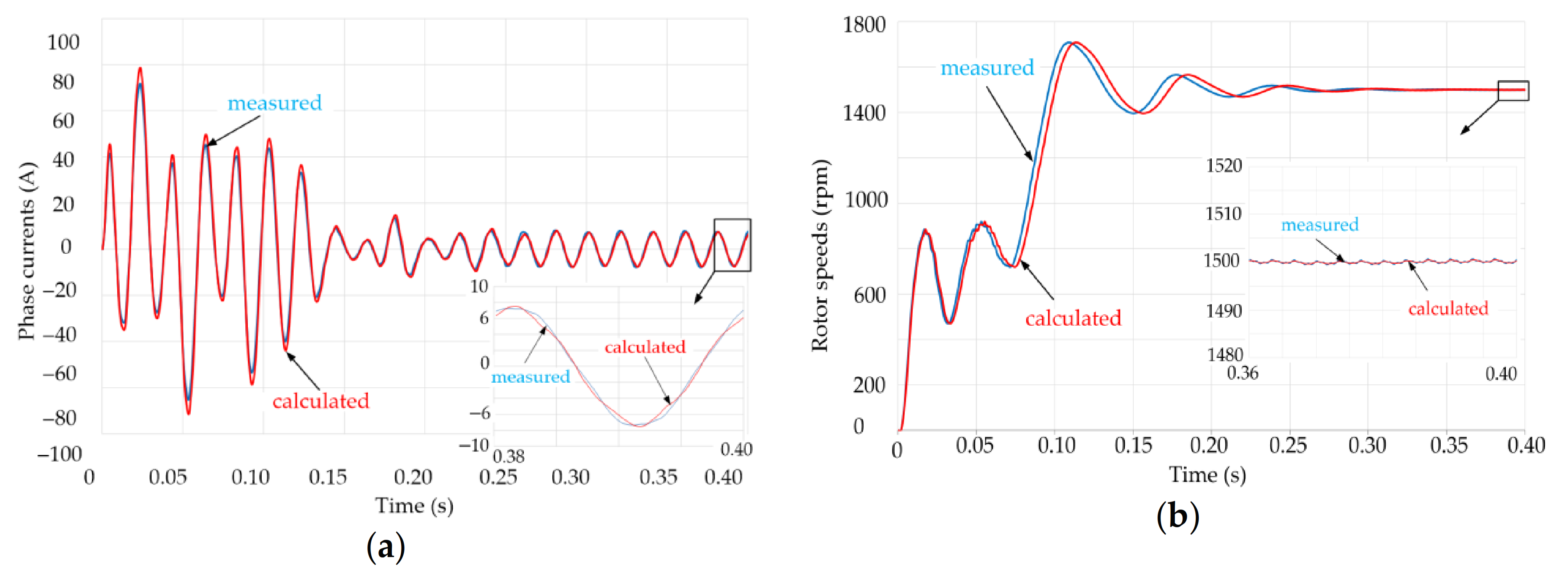
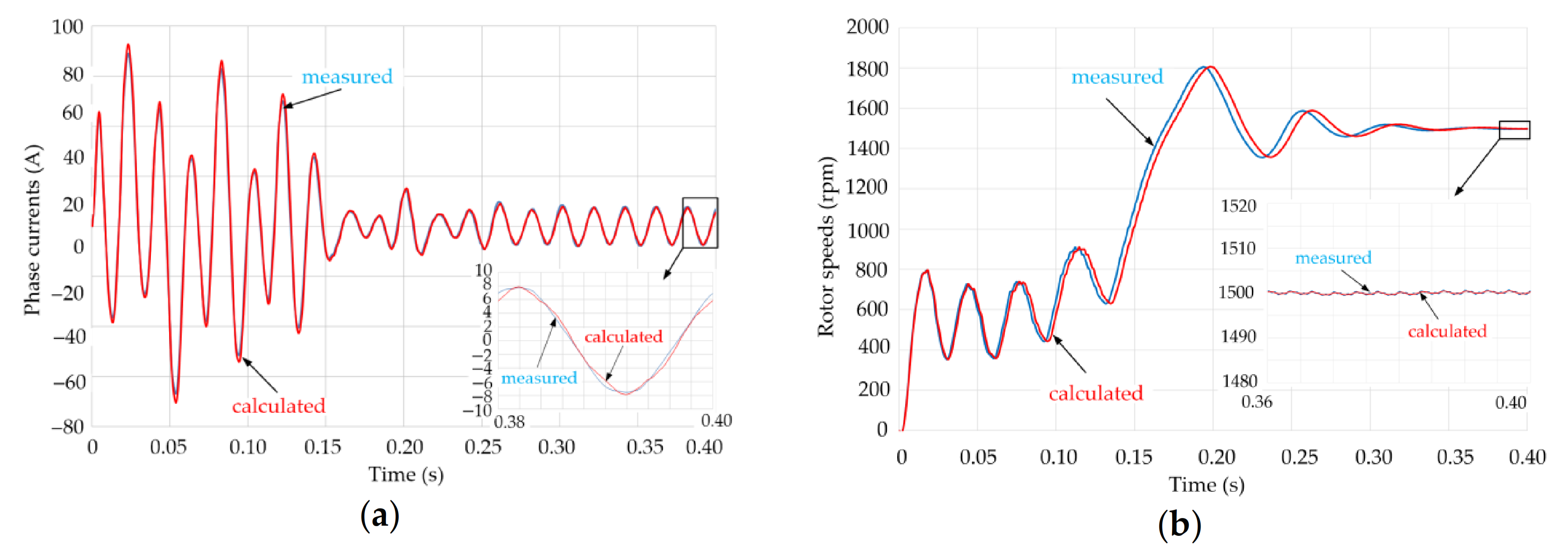
In order to illustrate this stage of the research,
Figure 7,
Figure 8,
Figure 9 and
Figure 10 summarize the compiled time curves of one of the phase currents and the rotational speed obtained during the motor’s start-ups performed for selected values of the load torque
and initial temperature
of the motor. In addition, the figures show a close-up of steady-state operations of current and time curves for the last considered supply voltage period. However,
Table 3 compiles the
RMS values of
and
for phase currents, accordingly calculated and measured for the implemented test variants. These are
RMS values of currents for the electromechanical steady-state obtained immediately after start-ups of the motor.
The comparison of the simulation and experimental results presented above shows that the developed algorithm and program for analyzing coupled phenomena maps the influence of temperature on operation of LSPMSMs with a high degree of reliability.
For this reason, the software was used to model the effect of temperature on the course of motor dynamics and on the process of partial demagnetization of permanent magnets. It should be emphasized that the advantage of the proposed approach, in addition to the lack of fear for demagnetization of the magnets during the experimental research, is low cost and short calculation time. The simulation tests, similarly to the tests verifying the developed software presented above, were carried out for the given load moments and initial temperature values = τ (t = 0) of motor components. It was assumed that the motor was supplied by a symmetrical three-phase voltage system with an RMS value of 400 V. In addition, all calculations assumed the same initial rotor position relative to the stator, the same phase of supply voltage, and that the magnets were fully magnetized before the start-up process.
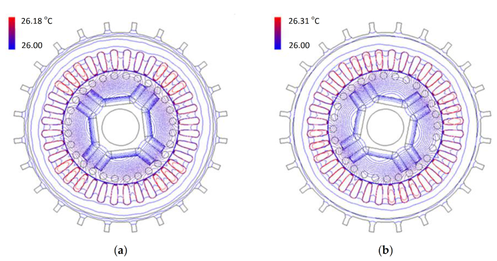
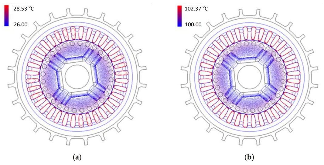
First, it was examined how the motor starting process affects the value and temperature distribution in the machine immediately after the starting process, for
t = 0.6 s. After this time, the electromechanical steady-state was obtained for each of the analyzed start-ups. Exemplary temperature distributions in the motor after the start-up process, for the time
t = 0.6 s, are shown in
Figure 11 and
Figure 12. The initial temperature (equal to the ambient temperature) and the highest temperature in the machine can be read from the temperature scales located in the upper left corner of the figures. The highest temperature values are in the area of the stator’s winding. Based on the drawings, one can determine the temperature rises Δ
τ in the machine during the start-up processes. They were defined as differences between the maximum temperatures and ambient temperature. It was found that the increases of Δ
τ were negligible in the no-load motor and they slightly increased with the increasing load and moment of inertia of rotating elements. The highest temperature increase Δ
τ of approximately 2.5 °C (
Figure 12a) was obtained at the start of the motor that runs the system characterized by a very high moment of inertia of the rotating masses and negligibly low anti-torque (the motor was not started at a load greater than zero). The calculations also show that the initial temperature of the motor components was slightly affected by the temperature rise.
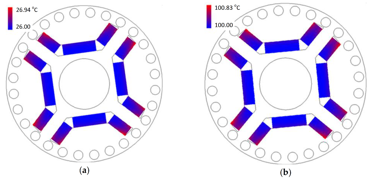
However,
Figure 13a,b show the temperature distributions in the magnets corresponding to the temperature distributions in
Figure 12a,b, respectively. From the above it follows that the highest temperature have the magnet sub-areas near the rotor cage winding, and the maximum temperature increase in the magnet area does not exceed 0.94 °C.
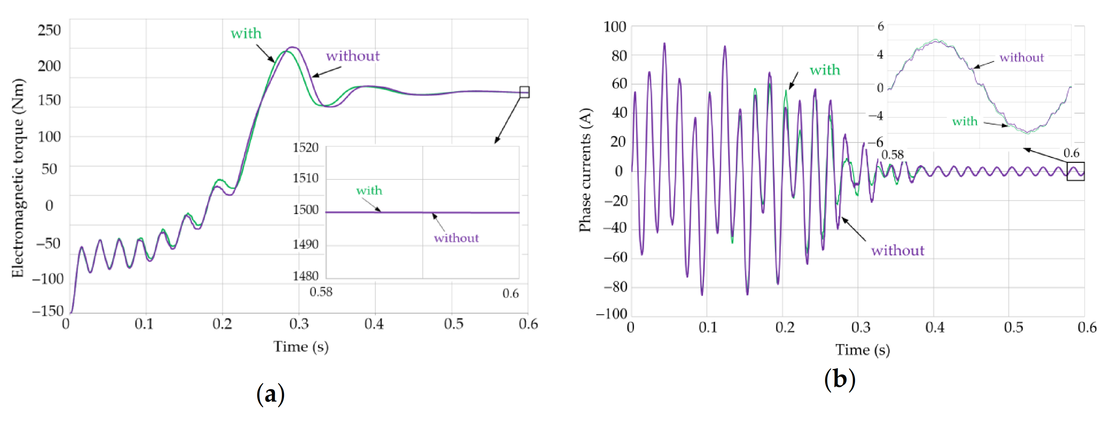
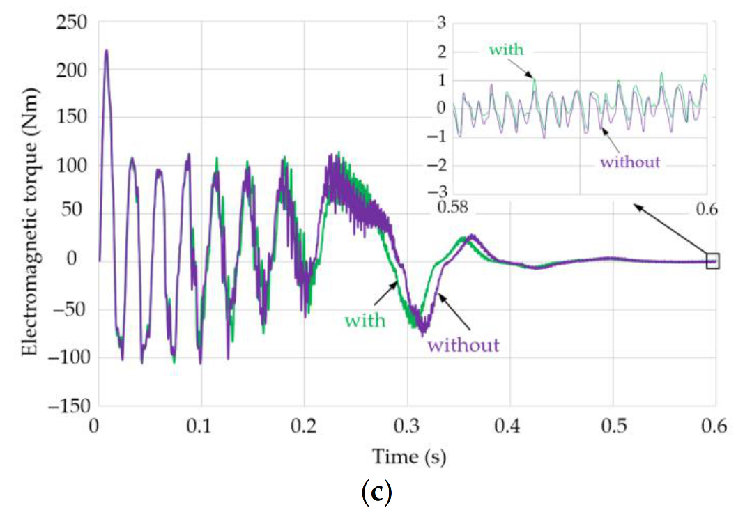
In the next stage of the research, it was analyzed to what extent the temperature of the electrical, thermal and magnetic properties of the materials affected the motor starting process. The paper contains results of the calculations only for the start-up process, for which the largest increase in temperature was observed.
Figure 14a–c show the time curves of the rotor speed
n(
t), phase current
(
t) and electromagnetic moment
(
t) determined without taking into account the effect (without) and the effect (with) of temperature on the course of the start-up process. A comparison of the time curves obtained shows the visible effect of temperature on the start-up process, thus it is advisable to consider changes in the properties of the materials as influenced by that temperature.
Figure 14b shows that the motor start-up is accompanied by high overcurrents. The impact values of the magnetomotive force of the stator associated with these currents can lead to partial demagnetization of the magnets in the rotor. The susceptibility of the magnets to partial demagnetization increases with increasing temperature. In order to assess and visualize the degree of partial demagnetization of the permanent magnets, the location of the
S(
) point (see
Figure 2) on the
B(
H,
τ) characteristic describing the material properties was analyzed in each elemental sub-magnet. It was assumed that the elemental sub-areas coincided with the elements of the grid discretizing the area of the permanent magnets. When assessing and visualizing the degree of partial demagnetization in all the elemental sub-areas, the values
for the magnetic flux density, before and after the motor starting, were compared.
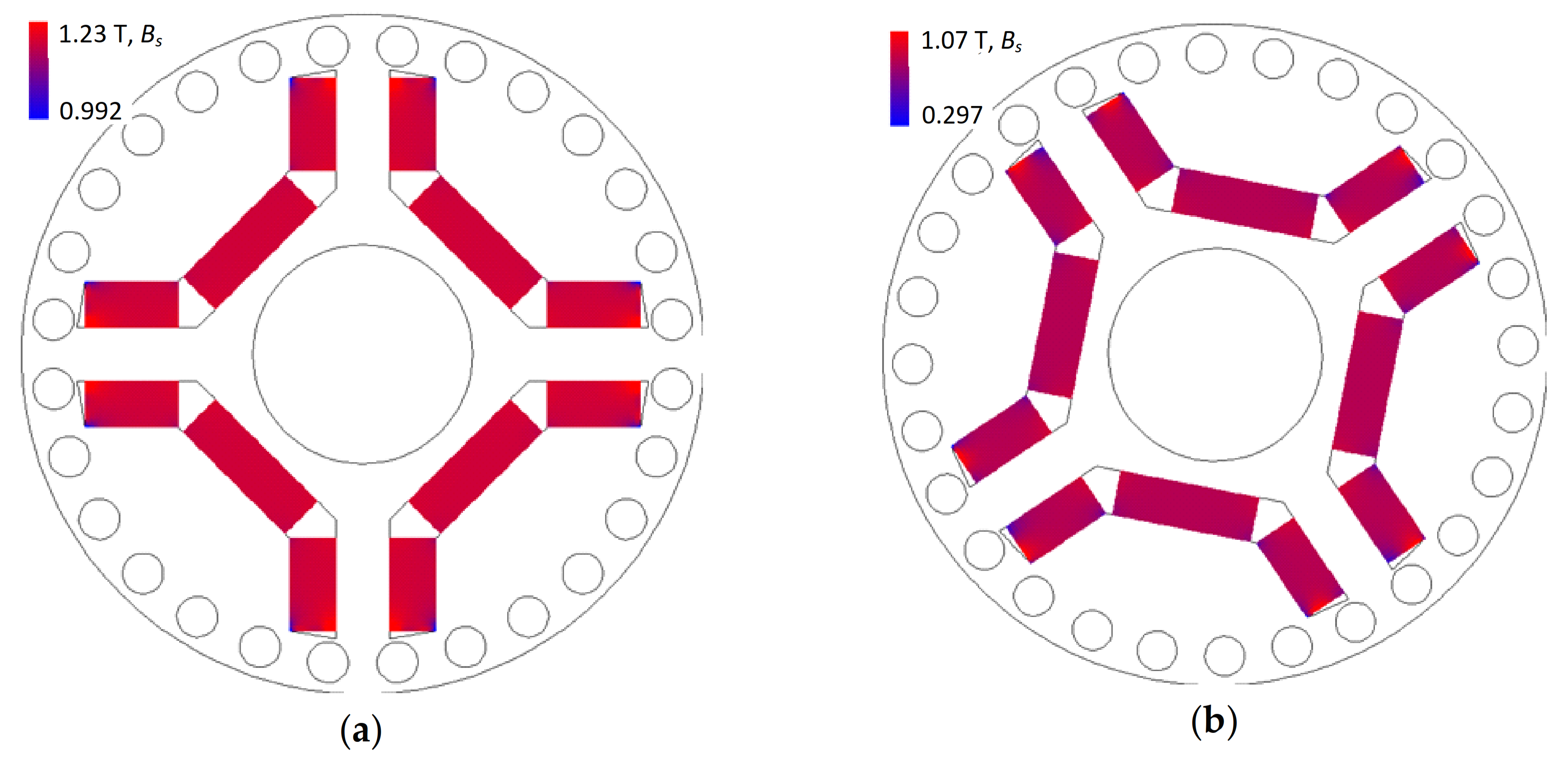
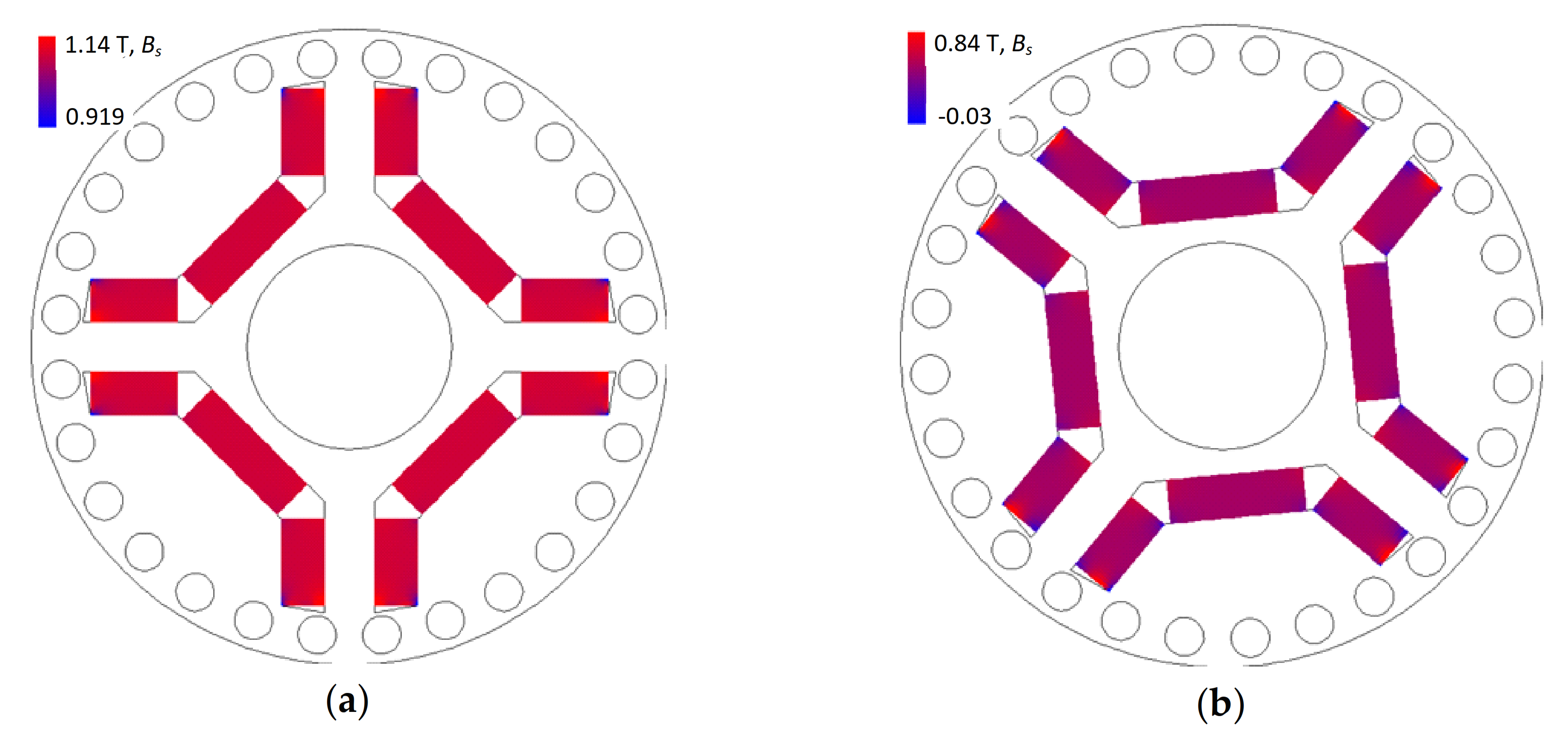
The effect of temperature on the magnetic flux density distributions
Bs before and after the start-ups is shown in
Figure 15 and
Figure 16. It follows that the magnetic flux density distributions
Bs before the start-up depend only on the temperature of the magnets. However, the magnetic flux density distributions
after the start-up depend additionally on the moment of load and the moment of inertia of the rotating masses. The magnetic flux density values
can even have values lower than zero. It should be emphasized, however, that the negative value of the magnetic flux density
does not clearly determine the partial demagnetization of the elemental sub-area. It has been assumed that partial demagnetization of the elemental sub-area takes place if the working point
S moves below the bend of the
B(
H,
τ) characteristic (see
Figure 1 and
Figure 2). Thus, partial demagnetization can also take place when the magnetic flux density
> 0.
To visualize the sub-areas of the magnet in which partial demagnetization occurred, a procedure that determines whether the operating point
S of the sub-area is on the straight part of the
B(
H,
τ) characteristic (see
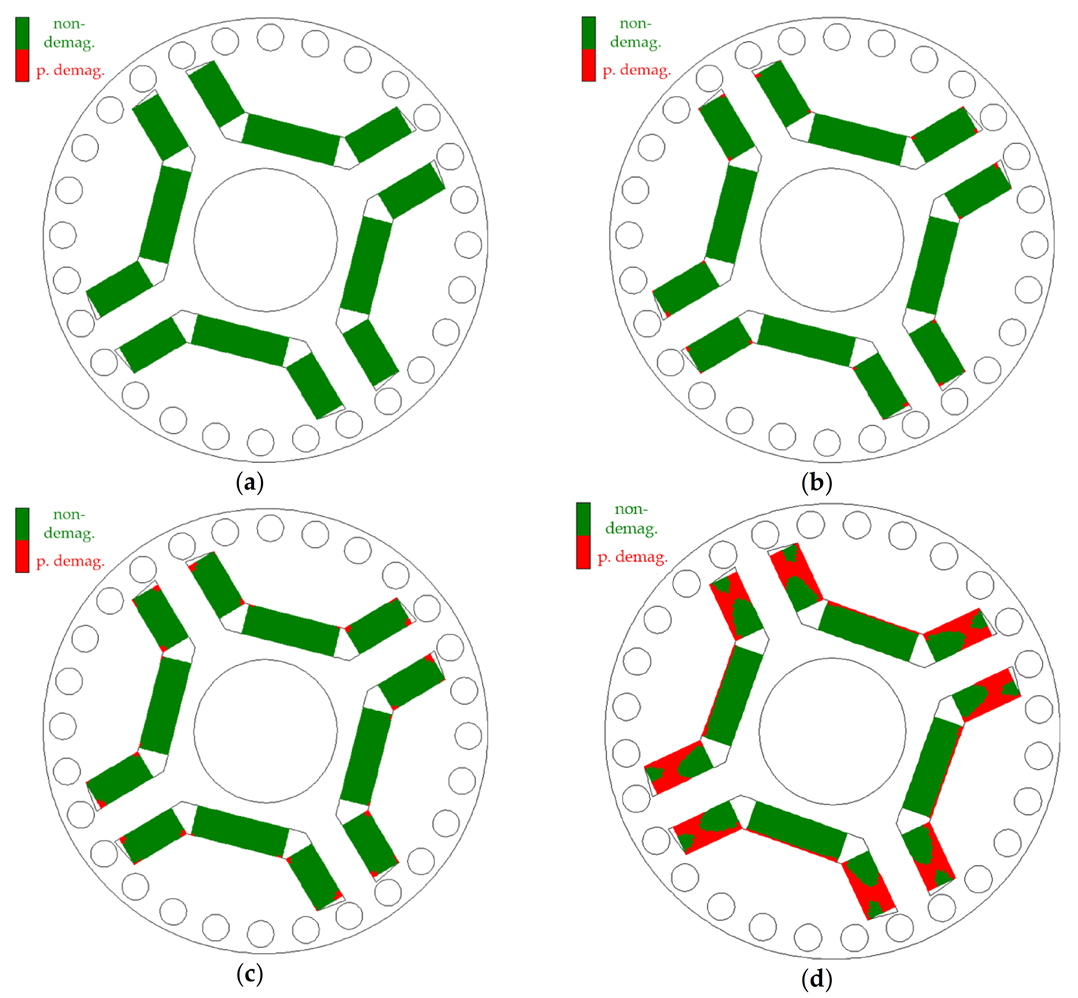
Figure 1) has been added to the developed software. The effects of this procedure are shown in
Figure 17a–d. The elemental sub-areas for which the work point is located on the straight part of the
B(
H,
τ) characteristic are marked on a computer screen in green. In contrast, the sub-areas in which the magnets were partially demagnetized were highlighted in red. The motor operating conditions specified in the description of
Figure 17a did not cause partial demagnetization of the motor. The remaining figures show the sub-areas in which the magnets were partially demagnetized. The simulation studies show that the magnets are most exposed to partial demagnetization in the sub-areas located around the edges of the magnets. The areas of partial demagnetization enlarge with the increasing temperature
τ of the magnets before starting the motor.
Figure 17d shows the areas of the magnets that were partially demagnetized after the starting process with a magnet temperature of 140 °C. It shows that almost all of the magnets were partially demagnetized.
A coefficient
δDE% was proposed to assess the degree of partial magnetization of the magnets in the motor:
where
and
are the
RMS values of the voltage
e(
t) determined for the same temperature of the machine components before and after the process of partial demagnetization of the magnets.
The values of the coefficient
after the start-up processes carried out for
= 19.5 Nm,
= 0.0082 kgm
2 (see
Figure 17a–d) are summarized in
Table 4. The table shows that after the start-up carried out at a temperature of 140 °C, the electromotive force and thus the main magnetic flux in the machine, decreased by over 8.588%.
It should be emphasized that due to the possibility of partial demagnetization, the most dangerous factors are dynamic states occurring at high temperature of magnets. Despite the high temperature of the magnets, such high exposure to demagnetization is not found in steady-state conditions. It follows that in steady-state conditions, there are no impact currents in stator windings. Partial demagnetization of motor excitation magnets leads to the irreversible reduction of the main flux and permanent deterioration of the nominal parameters of the machine.


