Review

An Overview of Applications of the Modular Multilevel Matrix Converter

1
Electrical Engineering Department, University of Santiago of Chile, Avenida Ecuador 3519, Santiago 9170124, Chile
2
Electrical Engineering Department, University of Chile, Avenida Tupper 2007, Santiago 8370451, Chile
3
Electrical Engineering Department, Universidad Técnica Federico Santa María, Valparaíso 1680, Chile
4
School of Electrical Engineering, University of Costa Rica, San José 11501-2060, Costa Rica
5
PEMC Group, Faculty of Engineering, University of Nottingham, Nottingham NG7 2RD, UK
*
Author to whom correspondence should be addressed.
Energies 2020, 13(21), 5546; https://doi.org/10.3390/en13215546
Submission received: 10 July 2020 / Revised: 16 September 2020 / Accepted: 6 October 2020 / Published: 22 October 2020
(This article belongs to the Special Issue Control Strategies for Power Conversion Systems)

Abstract

:
The modular multilevel matrix converter is a relatively new power converter topology suitable for high-power alternating current (AC)-to-AC applications. Several publications in the literature have highlighted the converter capabilities, such as full modularity, fault-redundancy, control flexibility and input/output power quality. However, the topology and control of this converter are relatively complex to realise, considering that the converter has a large number of power-cells and floating capacitors. To the best of the authors’ knowledge, there are no review papers where the applications of the modular multilevel matrix converter are discussed. Hence, this paper aims to provide a comprehensive review of the state-of-the-art of the modular multilevel matrix converter, focusing on implementation issues and applications. Guidelines to dimensioning the key components of this converter are described and compared to other modular multilevel topologies, highlighting the versatility and controllability of the converter in high-power applications. Additionally, the most popular applications for the modular multilevel matrix converter, such as wind turbines, grid connection and motor drives, are discussed based on analyses of simulation and experimental results. Finally, future trends and new opportunities for the use of the modular multilevel matrix converter in high-power AC-to-AC applications are identified.

Graphical Abstract

1. Introduction

Modular multilevel cascaded converters (MMCCs) have attracted considerable attention from the power electronic and drive research community since its introduction at the beginning of the 2000s [1]. Originally, MMCCs were proposed for high voltage direct current (HVDC) transmission systems, but recently, they have been introduced into other fields, e.g., static compensators (STATCOMs) [2,3,4], wind energy conversion systems (WECSs) [5,6], drives [7,8], etc.
Some of the well-known advantages of MMCCs are related to their modular topology, which allows a relatively simple expansion to higher voltages and powers; redundancy; high efficiency; robustness; and high power quality [9]. For instance, if a larger nominal voltage is required, more power-cells can be cascaded into each cluster; if a larger nominal current is required, then power-cells can be paralleled. Moreover, redundancy is simple to provide by including a number of additional power-cells in each cluster, which can be activated to replace those damaged or in a faulty condition.
Among MMCCs, the modular multilevel converter ( M 2 C ) is a well-established topology used extensively for HVDC transmission [2,10,11], and more recently in motor-drive applications [12,13,14,15] with some solutions being commercially provided to the market [12,13].
However, as it has been reported in several publications, the M 2 C has some difficulties in achieving good performances in applications where the electrical machine is operating at very low-speed (low stator frequency) and at high-torque. Moreover, the M 2 C is not an AC-to-AC topology, and a back-to-back connection is required if AC-to-AC conversion is necessary, and this increases the numbers of semiconductor switches, capacitors and inductors. Therefore, other MMCC topologies, such as the Hexverter and the modular multilevel matrix converter ( M 3 C ), have been studied in the last few years [16,17] for high-power AC-to-AC drive applications. In particular, the M 3 C has shown some advantages when the control of electrical machines operating at low-speed and high-torque is required. Moreover, as reported in several publications [18,19,20], for this operating range, the M 3 C has advantages when compared to other MMCC topologies. Currently, several works have highlighted the M 3 C as a suitable AC-to-AC topology for high-power motor-drive applications [8,18,21].
A matrix converter topology with a resemblance to the modern M 3 C was first proposed by a research group from the National Renewable Energy Laboratory for high-power WECSs [22,23,24]. In this topology, filter inductances were not included in each cluster, and this produces several drawbacks. For instance, as reported in [23], only five clusters were permitted to be switched on (simultaneously) to avoid the problems of producing a short circuit by parallel connection of voltage sources. This problem was solved in [25] by introducing cluster inductors (see Figure 1) allowing a continuous and regulated cluster currents flow; i.e., with the addition of the inductances each cluster could be represented as a controllable current source.
The topology of the M 3 C currently being used is shown in Figure 1. The converter is composed of nine clusters comprising a stack of series-connected full-bridge power-cells and one inductance. Each power-cell is composed of a full-bridge connected to a floating capacitor on the DC-side. The voltage in this capacitor has to be well regulated in order to achieve proper and stable operation of the converter in the whole operating range [18]. The capacitor voltage regulation is usually performed using four linearly independent circulating currents [26,27]. In this work, the term circulating current is utilised to refer to the internal currents of the converter which are neither present at the input a-b-c nor present at the output r-s-t terminals.
Figure 1. M 3 C topology. From [28].
Energies 13 05546 g001
In the M 3 C , the AC-to-AC power conversion is performed without using a DC-link, which eliminates the capacitor voltage fluctuations when the converter operates with a low-frequency on the output-side [29,30]. Consequently, in this operating point, lower circulating currents and common-mode voltage are required to mitigate the capacitor’s voltage oscillations compared with those typically required in the M 2 C [8,21]. This advantage makes the M 3 C a promising topology for high-power variable-speed drive applications, such as medium-voltage motor drives [8,21,31], gearless Semi-Autogenous Grinding (SAG) mills [32], offshore wind-power generators [27] and full-electric marine propulsion systems [33], where the M 3 C can substitute the line-commutated converters to reduce current harmonics, to improve the power factor and to increase the efficiency and flexibility. Additionally, in contrast to the back-to-back M 2 C topology, the M 3 C can still be operated after a failure in a power-cell or a whole cluster, regardless of the cluster in which the failure occurred [34].
Unlike the M 2 C , at the present time, there are no commercial solutions available for the M 3 C . That is probably because the M 3 C is more complex to control, has a high component count and is more costly to build. However, it is forecasted that shortly the M 3 C will replace the conventional thyristor-based cycloconverters utilised for the control of high-power machines, e.g., the SAG mills, as reported in [26]. Complex implementation and control have also hindered the number of works where experimental results of this topology are reported. This is further discussed in the next sections.
This work aims to provide an extensive and thorough review of the state-of-the-art of the M 3 C . This review paper is focused on describing practical implementations and applications, such as the utilisation of the M 3 C in wind turbines and motor-drive systems. The contributions of this paper can be summarised as follows.
  • To the best of the authors’ knowledge, this is the first review paper discussing and comparing experimental implementations and applications of the M 3 C . In the field of MMCCs, there are other review papers available for the M 2 C [2,9,35,36,37] and Hexverter [16]; comparisons between the M 2 C and M 3 C for motor-drive applications [8,21]; and modelling and control approaches for the M 3 C (a recent review) [28]. However, those papers neither describe practical issues related to the implementation of the M 3 C nor describe applications of the M 3 C .
  • Some of the most well-known implementations of the M 3 C reported in the literature are listed and classified.
  • In this paper, guidelines to designing and dimensioning the most important electrical parameters of the M 3 C are described.
  • The M 3 C is compared to other MMCCs, such as the Hexverter and the M 2 C , in terms of component counts and effectiveness. Results were obtained for a 10 MW case of study.
  • Furthermore, a review of promissory applications for the M 3 C , such as wind energy, motor drives and flexible AC transmission systems (FACTSs), is presented. Simulations and experimental results are given to support the effectiveness of the topology in these applications.
The rest of this paper is organised as follows. Design guidelines and the details of the currently implemented M 3 C prototypes are presented in Section 2. Then, the M 3 C , Hexverter and M 3 C are compared in terms of flexibility, component counts and other technical parameters in Section 3. Section 4 presents a summary of M 3 C applications such as wind turbines, motor drives and FACTSs. After that, future research opportunities and trends and identified in Section 5. Finally, an appraisal of the applications discussed in this paper is presented in the conclusions.

2. M3C Control and Hardware Challenges

The M 3 C is composed of nine cluster, as illustrated in Figure 1. Normally, each cluster of the M 3 C can be represented as a controllable voltage source to simplify the analysis of the converter, as presented in Figure 2b [27]. The connection of three clusters linking the three phases of the input system (e.g., phases a , b , c ) to one phase of the output system (e.g., phase r) has been referred to as a sub-converter or single-phase M 3 C [32]. The composition of a sub-converter is presented in Figure 2c. Additionally, the composition of each cluster comprises the connection of n power-cells connected in cascade with one inductor L c , as depicted in Figure 2d. Finally, the power-cell comprises a full-bridge connected to a DC capacitor, as presented in Figure 2d.
In this converter, the number of power-cells can be increased to reach higher power and voltage ratios. Therefore, the control and hardware of the converter must be designed to handle the possible addition of more power-cells. Additionally, as the voltages in the capacitors of each power-cell are floating, the regulation of the M 3 C must ensure a good regulation of these floating capacitor voltages over all the operational range. These two facts can be complicated to accomplish, as indicated in some publications [17,28,32]. Consequently, in the following subsections, the main highlights regarding the modelling, control and nature of the voltage oscillations are briefly revised. More details regarding these topics can found in [28].

2.1. Control Issues and Floating Capacitor Voltage Oscillations

Analysing the circuit diagram depicted in Figure 1a, the nine cluster voltage equations of the M 3 C can be expressed as follows:
v m a v m b v m c v m a v m b v m c v m a v m b v m c V m x = L c d d t i a r i b r i c r i a s i b s i c s i a t i b t i c t I x y + v a r v b r v c r v a s v b s v c s v a t v b t v c t V x y + v g r v g r v g r v g s v g s v g s v g t v g t v g t V g y + v n 1 1 1 1 1 1 1 1 1
In Equation (1), the subscript m is used to represent the input-side voltages and currents; meanwhile, the subscript g is used to represent the output-side variables. The voltage between external neutral points is denoted by v n .
If the voltage drops in the cluster inductors are neglected, and neither common-mode voltage nor circulating currents are utilised, the cluster voltages and the cluster currents can be expressed in terms of the input and output matrices as follows:
V x y = V m x V g y
I x y = 1 3 ( I m x + I g y )
where I m x and I g y are input and output current matrices; V m x and V g y are input and output voltage matrices. Note that x { a , b , c } and y { r , s , t } . Considering that each cluster is composed of n full-bridge power-cells, every component of the V x y matrix can be expressed as follows:
v x y = i = 1 n v x y , i = i = 1 n S x y , i v C x y , i
In Equation (4), v x y , i stands for the voltage synthesised at the output of each power-cell, the switching state of each power-cell is represented by S x y , i { 1 , 0 , 1 } and v C x y , i is the floating capacitor voltage of the ith power-cell within the cluster x y .
Additionally, the sum of all the voltages within a cluster is referred to as the cluster capacitor voltage (CCV) as follows:
v C x y = i = 1 n v C x y , i
Using the CCV definition, is possible to define the CCVs matrix:
V C x y = v C a r v C b r v C c r v C a s v C b s v C c s v C a t v C b t v C c t
The CCVs represent the total capacitor voltages available in clusters, and they are dependent on the instantaneous active power of their clusters. This instantaneous active power can be expressed as a function of the cluster currents and voltages. Thus, the cluster power matrix is determined as:
P x y = ( V m x V g y ) 1 3 ( I m x + I g y )
The symbol “∘” represents the Hadamard product (element by element product). Then, the CCVs can be related to the cluster power components as follows:
d d t V C x y P x y C v C *
Note that in Equation (8), the power losses and the voltage drops in the inductances are neglected (see [38]). It is also assumed that neither common-mode voltage nor circulating currents are utilised. In addition, v C * is defined as the desired average capacitor voltage in each power-cell and C is the capacitance of each power-cell capacitor.
By substituting Equation (7) into Equation (8) and after some manipulations it could be shown that low-frequency instantaneous capacitor voltage oscillation of large magnitudes could be obtained in some operating points [32]. To illustrate this fact, the nine CCVs of an M 3 C are plotted as a function of the output port frequency, representing the typical operation obtained when a electrical machine with an almost linear back electromotive force versus rotational speed characteristic is fed by the M 3 C (see Figure 3). Notice that the CCVs are normalised by n v C * to obtain a per-unit representation. The input-port frequency ( f m ) is varied from 60 Hz to 60 Hz, whereas the output-port frequency ( f g ) is set at a fixed value of 50 Hz. Notice that considerable voltage oscillations are produced when f m is very close or equal to ± f g . In other cases, i.e., when the frequency difference between the input and output voltage ports is relatively large, the CCV oscillations are not considerably high.
The operation of the M 3 C is usually divided into the different frequency mode (DFM) and the equal frequency mode (EFM), as depicted in Figure 3. Both modes can be defined as indicated in [39,40]:
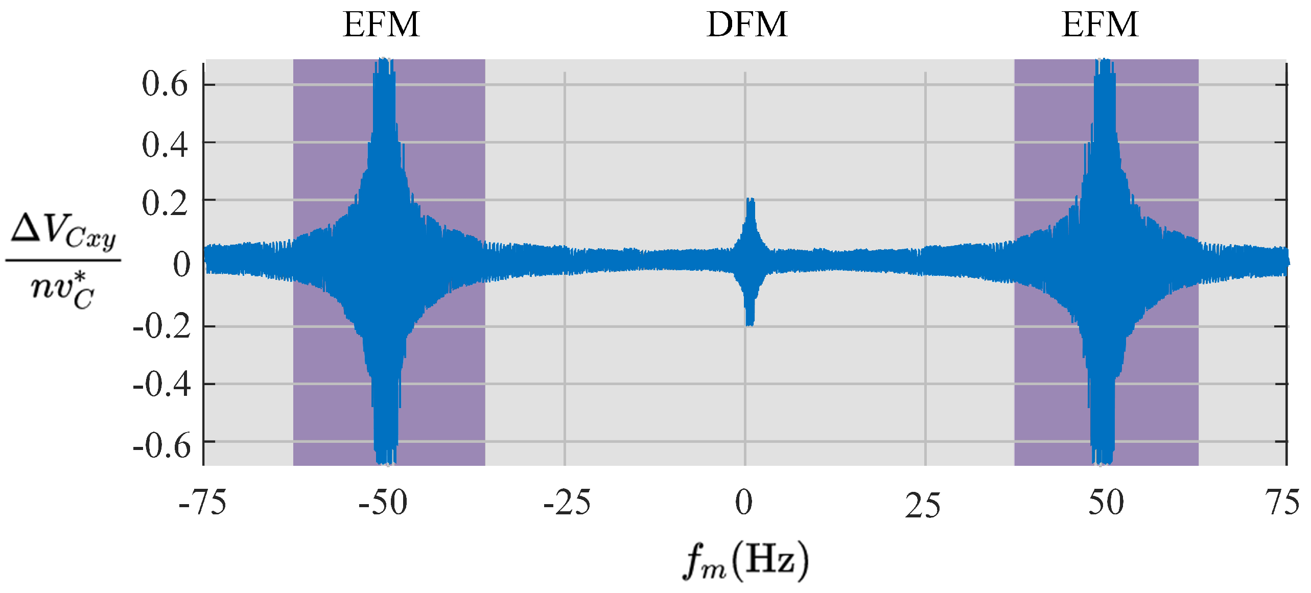
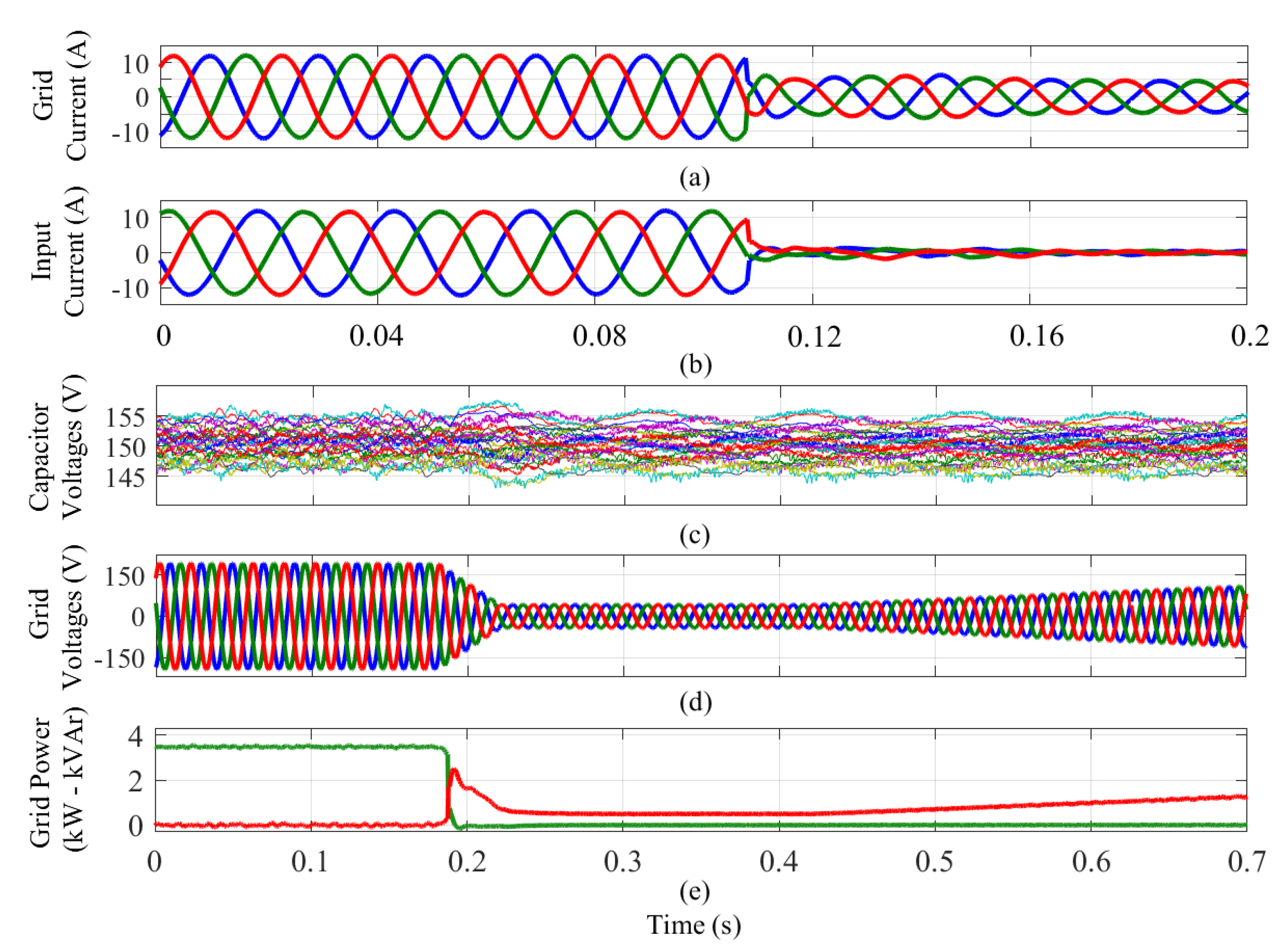
  • The DFM is defined as the zone where the input-port frequency is lower or higher (by a given threshold) than the output-port frequency. In this mode, the floating capacitor voltage oscillations are not high (see Figure 3). Then, the control of the M 3 C needs to regulate just the mean values of the floating capacitor voltages using mostly circulating currents.
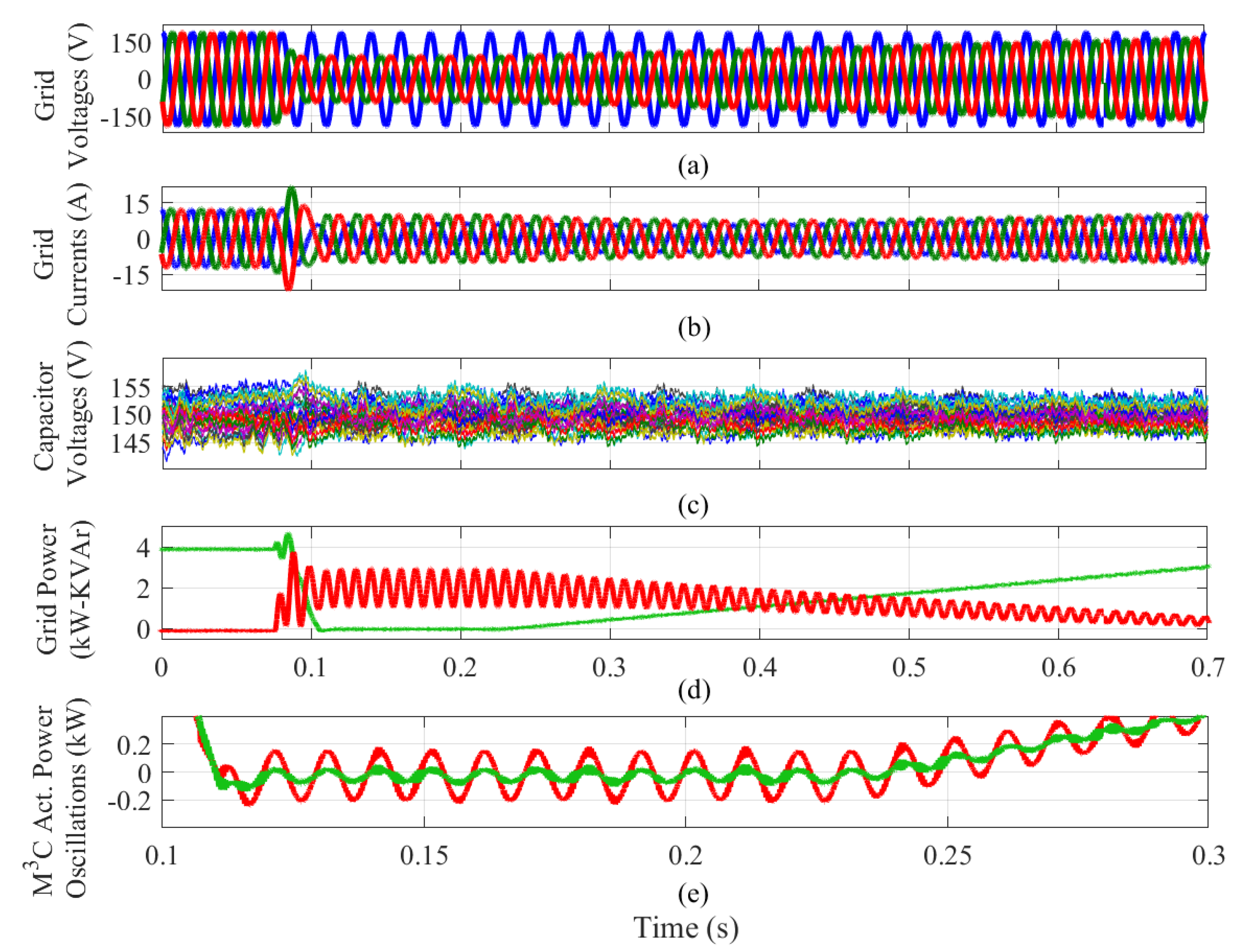
  • The EFM is defined as the zone where the absolute value of the input-port frequency is pretty close or equal to the output-port frequency, i.e., f m ± f g . In EFM, high oscillations appear in the floating capacitor voltages, and then mitigation signals (circulating currents and common-mode voltage) or operation point constraints must be employed to reduce them.

Control Issues

The control of the floating capacitor voltages is fundamental to provide stability and safety, especially in the critical operating points depicted in Figure 3. For the case f m = 0 , the CCV oscillations are somehow reduced when compared to those produced at the other critical operating frequencies. This feature is because, in a typical drive application, the back-emf of the electrical machine is low at low rotational speed, reducing, therefore, the power and voltage oscillations calculated using Equations (7) and (8) (see [39,41]). Nonetheless, due to the integrating effect of the capacitors, CCV regulation is required over the full frequencies range because even small power variations can produce significant voltage imbalances [27]. In the cases when f m ± f g , the CCVs can be unstable and the use of mitigation control systems is required. As indicated in [42], additional circulating currents for mitigation purposes and the injection of common-mode voltage are required to prevent unstable voltages in the M 3 C , ensuring stable operation of the converter.
Typically, the control of the M 3 C is performed using nested-control structures to achieve, at least, the following control targets [8,38,39]:
  • The control of the input and output currents.
  • The control of the floating capacitor voltages.
  • The minimisation of circulating currents and common-mode voltage (CMV).
Nested control systems based on decoupled modelling of the M 3 C have been proposed in the literature [26,27,38,39,43,44]. These methodologies enable a decoupled control on input currents I m x , output currents I g y and circulating currents I z of the M 3 C . As each control system is decoupled, it is possible to regulate the floating capacitor voltages without affecting the input and output port systems. Linear transformations are used to enable the use of the common-mode voltage v n and the circulating currents I z to regulate the CCVs. Up to date, the most effective approaches seem to be those based on a double Clarke transformation, referred to as a double− α β γ transformation [38,44], and a Σ Δ transformation referred to as diagonal [41] or Σ Δ double– α β γ transformation [39].
Most of the control systems reported in the literature (e.g., [26,27,38,39,43,44]) are based on the three-stage nested control structure shown in Figure 4. The outer control stage regulates the CCVs and the control of the input and output port variables. Typically, the outputs of the outer control stage are the references required for the currents located in the inner control loops (e.g., the circulating currents I z * ). The second control stage regulates the currents in a decoupled manner. The control systems depicted in Figure 4 are typically based on standard and well-known vector control methods (e.g., field- and voltage-oriented control techniques [45,46,47]), with the circulating currents being regulated using proportional controllers [38,48]). Finally, the third control stage is used to locally balance the floating capacitor voltages in the power-cells within the same cluster. In this case, most of the control strategies discussed in the literature (e.g., [30,49,50]) to perform this task are based on using additional compensating signals for each cell or sorting algorithms.
The main research challenges related to the M 3 C control are summarised below. Additional details regarding this topic are addressed in [28].
  • One of the most critical control tasks is to maintain the floating capacitor voltages fluctuating within an acceptable range. The oscillations in the floating capacitor voltages are inversely proportional to the difference between the input and output port frequencies (i.e., | f m f g |). Then, the operation of the M 3 C for similar or equal input/output port frequencies is challenging to achieve because the large oscillations produced in the CCVs (see Equation (8)) must be mitigated using compensation currents and common-mode voltage [39,51].
  • The regulation of the internal currents of the M 3 C , referred to as circulating currents [18], plays a vital role in achieving effective floating capacitor voltage regulation. Then, the measurement and estimation of these currents must be performed while dealing with currents with several frequency components that must be regulated without affecting the input and output port variables [43].
  • In high-power applications, a high number of power-cells can be required, and then a very high number of possible voltage vectors can be obtained ( 3 9 n where n indicates the number of power-cells [27]). Therefore, some methodologies which are based on voltage states, for example, the space vector modulation techniques and/or finite set model predictive control, are very difficult to implement. Therefore, other modulation techniques and methods to achieve voltage regulation of the power-cell must be considered without increasing the complexity of the overall control system, ensuring proper voltage balancing and ensuring low power losses [52].

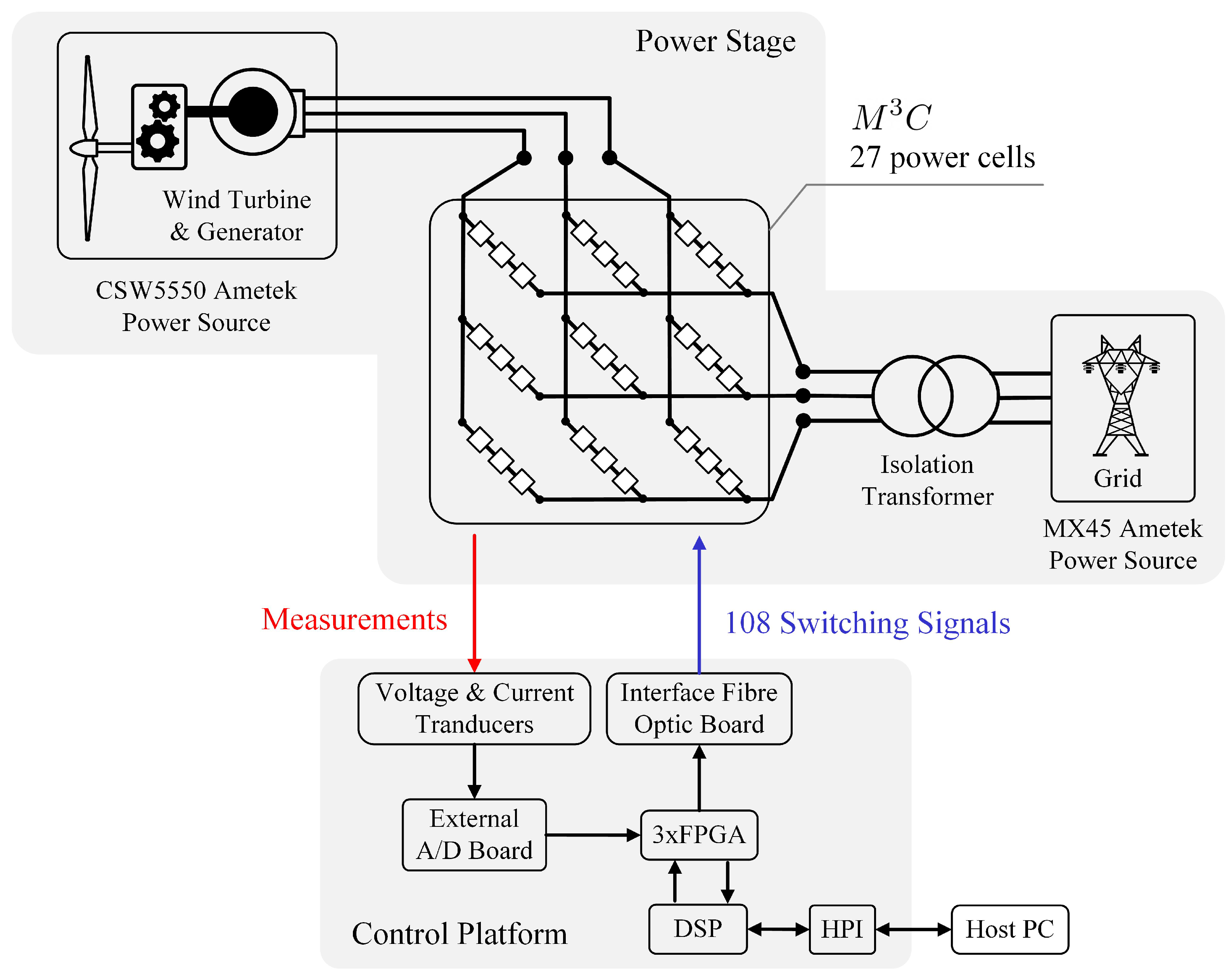
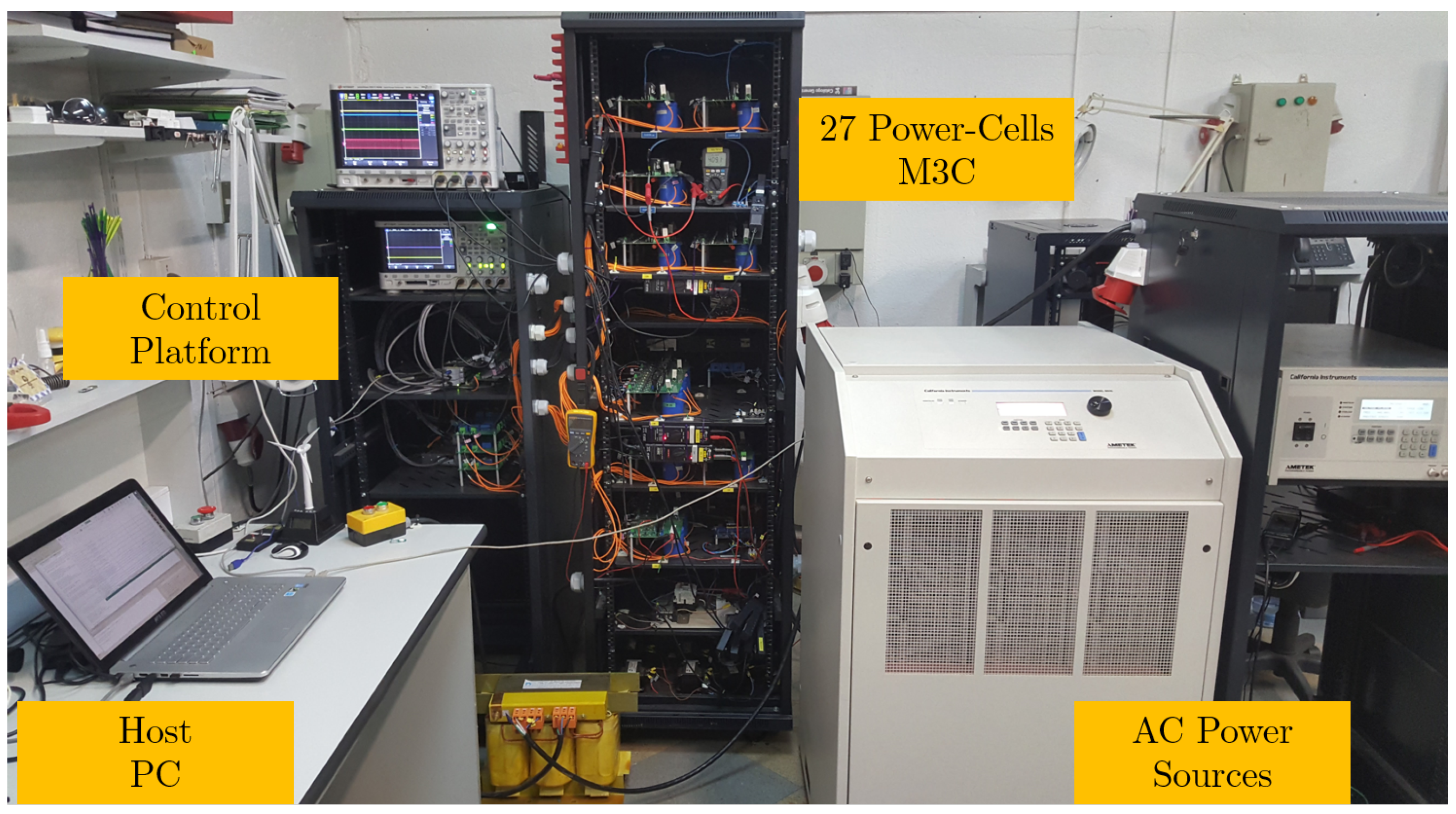
2.2. Hardware Implementations of M 3 C

As aforementioned, the M 3 C is considered a suitable power converter topology for high-power, variable-speed motor drives (including wind energy generators). Furthermore, the M 3 C has been suggested as an alternative to the traditional line-commutated cycloconverters and it is forecasted that in the future this thyristor based topology could be replaced by the M 3 C [26]. Nevertheless (as discussed above), until now there are no commercial solutions based on the M 3 C available on the market. Some of the reasons are the high component count, cost and control complexity required in this power converter. Therefore, more research is required in order to eliminate some of these drawbacks [26].
The control complexity and the high component count have also hindered the implementation of fully operational M 3 C prototypes. Consequently, few research groups have reported experimental verification of M 3 C applications. According to [8], until 2016, just four research groups had managed to build operational M 3 C prototypes. From that date until now, the research related to the M 3 C has been very active. A high number of new research proposals, validated through simulations and experimental work, focusing on the M 3 C , allows one to foresee an expansion of the current knowledge about this topology [43,53,54,55,56]. Further experimental work has also been produced in the last few years. Currently, approximately 18 journal papers reported experimental work, as listed in Table 1. These papers have been published by research groups from the University of Tokio [8,38,42,57,58], Tsinghua University [29,33,48] and the University of Santiago of Chile−University of Chile [27,39,40,59]. Furthermore, research groups from the Karlsruhe Institute of Technology [41,51,60] and the Leibniz Universitat Hannover [61] have published conference papers discussing decoupled control strategies for the M 3 C . These strategies have been validated through simulations and at least partially by experimental results.
Typically the experimental prototypes of M 3 C utilised in the publications presented in Table 1, are each composed of a control platform and a power stage. As a representative example, the circuit diagram of the experimental system employed in [27] is presented in Figure 5. In this case, a 27 power-cell prototype was utilised to perform research in the control system required for high-power wind turbine applications. The M 3 C was composed of nine clusters considering three full-bridge power-cells. The system was controlled using a digital signal processor (DSP) from Texas Instruments (Texas, USA), and three Actel ProAsic3 field programmable gate array (FPGA) (Aliso Viejo, USA) boards which were used for the Pulse Width Modulation (PWM), analogue-digital conversion and overcurrent-overvoltage protection tasks. The control platform was equipped with 50 14-bit analogue-digital channels and 54 optical fibre-based PWM channels. Additionally, two programmable Ametek (Berwyn, USA) AC power sources were utilised to emulate the electrical grid and the wind turbine.
Usually the M 3 C implementations reported in the literature are similar to the system shown in Figure 5. The control platforms consider the use of DSP and FPGA boards for control processing, computer communications, analogue–digital conversion and hardware protections. The power stage comprises the connections of full-bridge power-cells, cluster inductors and the input and output port related hardware. Currently, the research group from the University of Tokyo has developed the most complex M 3 C experimental prototype [38] reported in the literature. In this case, the prototype has 36 power-cells (four power-cells per cluster), and the control platform handles around 50 analogue measurements and 144 gate signals.

2.3. M 3 C Design and Dimensioning

Guidelines for the design of MMCCs have been investigated for the M 2 C , focusing on HVDC and motor-drive applications [9,66,67,68]. Nevertheless, the dimensioning of the M 3 C has only been discussed in a few papers [57,69]. Therefore, some guidelines regarding the voltage rating, number of power-cells, cluster inductor selection and the required size of the capacitors in the power-cells are discussed in this section. To this end, steady-state operating conditions are assumed, and thus, the following expressions are used to define each input (subscript m) and output port’s (subscript g) current and voltage:
v m x = V m cos ( ω m t + θ x )
i m x = I m cos ( ω m t + θ x + ϕ m )
v g y = V g cos ( ω g t + δ + θ y )
i g y = I g cos ( ω g t + δ + θ y + ϕ g )
where V m and V g are the phase-to-neutral voltage amplitudes, and I m and I g are the current magnitudes.
The angular frequencies are assumed as ω m = 2 π f m and ω g = 2 π f g . The angles ϕ m and ϕ g are the phase angles, which in turn are related to the reactive power injected/consumed at the output ports. The angle δ is the initial phase of the input port with respect to the output port at t = 0 . Besides, the angle θ x , with x { a , b , c } , stands for the phase angle related to the three-phase input systems, i.e., θ a = 0 , θ b = 2 π / 3 and θ c = 2 π / 3 . The phase angles θ y with y { r , s , t } can be defined accordingly.

2.3.1. Voltage and Current Rating

As the M 3 C performs direct connection of two AC ports, each cluster must be able to block, at least, the sum of the peak input and output voltages. Therefore, the CCV of a generic x y cluster must satisfy the following restriction:
v C x y V m + V g + V n = V C , m i n
where V C , m i n is the minimum voltage required in the CCVs and V n is the amplitude of the CMV.
On the other hand, the cluster current of a generic cluster x y , namely, i x y , is defined as follows:
i x y = 1 3 ( i m x + i m y ) + i z , x y
The circulating current component i z , x y in the cluster current depends on the operating point of the M 3 C , the control strategy used to regulate the CCVs and the maximum allowed floating capacitor voltage oscillations, among other variables. The amplitude of the circulating current is designed as a fraction of the cluster current without injecting circulating currents, leading to:
I z , m a x = η 1 3 ( I m + I g )
where η is a factor usually between 0 and 1. Therefore, the maximum cluster current must be designed to accommodate the input and output current components plus the circulating current as follows [58]:
I x y , m a x = 1 3 ( I m + I g ) ( 1 + η )

2.3.2. Number of Power-Cells

In the M 3 C , each cluster must be able to synthesise the same voltage; i.e., a generic cluster x y must have a voltage level of at least V C , m i n , as shown in Equation (13) [7]. The number of power-cells can be calculated based on the the blocking voltage of the semiconductors V i g b t utilised in the M 3 C . Thus, the number of power-cells is determined as follows:
n = V C , m i n V i g b t
Then, the floating capacitor voltage of each power-cell can be established as:
v C * = V C , m i n n
Additionally, some publications suggest to provide some level of redundancy in the converter [70]. One alternative is to design the power-cell to withstand a voltage higher than the nominal value. This methodology design allows getting a voltage margin which could be used in the event of a fault. For instance, for a redundancy of one, i.e., to enable a cluster to operate normally in the event of a faulty power-cell, the required nominal voltage in the capacitor voltage is:
v C * = V C , m i n n 1

2.3.3. Power-Cell Capacitor

The correct design of the power-cell capacitor is essential for a good performance of an M 3 C [20,69]. The capacitance has to be designed to buffer the peak energy variations, keeping the voltage oscillations bounded inside a suitable range. The energy stored in every cluster of the M 3 C is determined as follows:
w x y = 1 2 C i = 1 n v C x y , i 2
Then, by assuming that all the capacitor voltages have the same average voltage v C * , the energy variations of every cluster can be rewritten in terms of the voltage deviations of the CCVs Δ v C x y as:
Δ w x y = i = 1 n w x y v C x y , i Δ v C x y , i = C v C * i = 1 n Δ v C x y , i = C v C * Δ v C x y
Moreover, by taking into account Equation (8), the dynamic model for the energy variations in terms of the AC components of the instantaneous cluster power Δ P x y can be established as:
d d t Δ w x y = Δ P x y ,
It is worth mentioning that, in the absence of CMV and circulating currents, the energy variations in Equation (22) depend on the operating conditions of the external systems which define the AC components of the cluster power Δ P x y . From Equation (7), it is shown that these oscillating power components are given at the frequencies 2 ω m , 2 ω g and ω m ± ω g . Consequently, for the design, the total energy variation should be calculated considering the worst-case scenario. From this perspective, and following the methodology presented in [69], the maximum energy variation in a single cluster can be determined as:
Δ W x y , m a x = P g 9 ω m 1 cos ϕ m + 1 ω g ω m cos ϕ g + V m V g cos ϕ g + V g V m cos ϕ m 2 1 ω g ω m + 2 1 + ω g ω m
where P g = 3 2 V g I g cos ϕ g is the M 3 C output power.
At this stage, the capacitance of the power-cells can be easily calculated using Equations (21) and (23) when a maximum admissible voltage ripple Δ V C , m a x is defined for the floating capacitor voltages. Therefore, the minimum power-cell capacitance is given by:
C m i n = 1 n v C * Δ W x y , m a x Δ V C , m a x

2.3.4. Cluster Inductor

The design of cluster inductors is done by imposing a maximum value for the ripple of the cluster current [7]. This limit Δ I x y , m a x is usually set to a 10–15% of the nominal cluster current [57]. Then, the cluster inductor can be calculated as indicated in [7]:
L c = v C * + 0.5 Δ V C , m a x f s w Δ I x y , m a x
where f s w is the output switching frequency. Note that f s w is related to the modulation method utilised to generate the pulse signals in the M 3 C . For instance, if the Phase Shifted PWM (PS-PWM) method is employed, the output switching frequency is given by f s w = 2 n f c , where f c is the frequency of the carrier signals.
It is worth mentioning that Equation (25) can be used to select the value L c of the cluster inductor when single-phase inductors are used. Nevertheless, cluster inductors can have different configurations. The most straightforward approach is to implement nine single-phase, independent inductors. The use of three-phase, three-core coupled inductors or three-phase, single-core coupled inductors has been proposed to reduce the size and weight [7,17]. The designs and implementations of these configurations for the cluster inductors are discussed in [57].

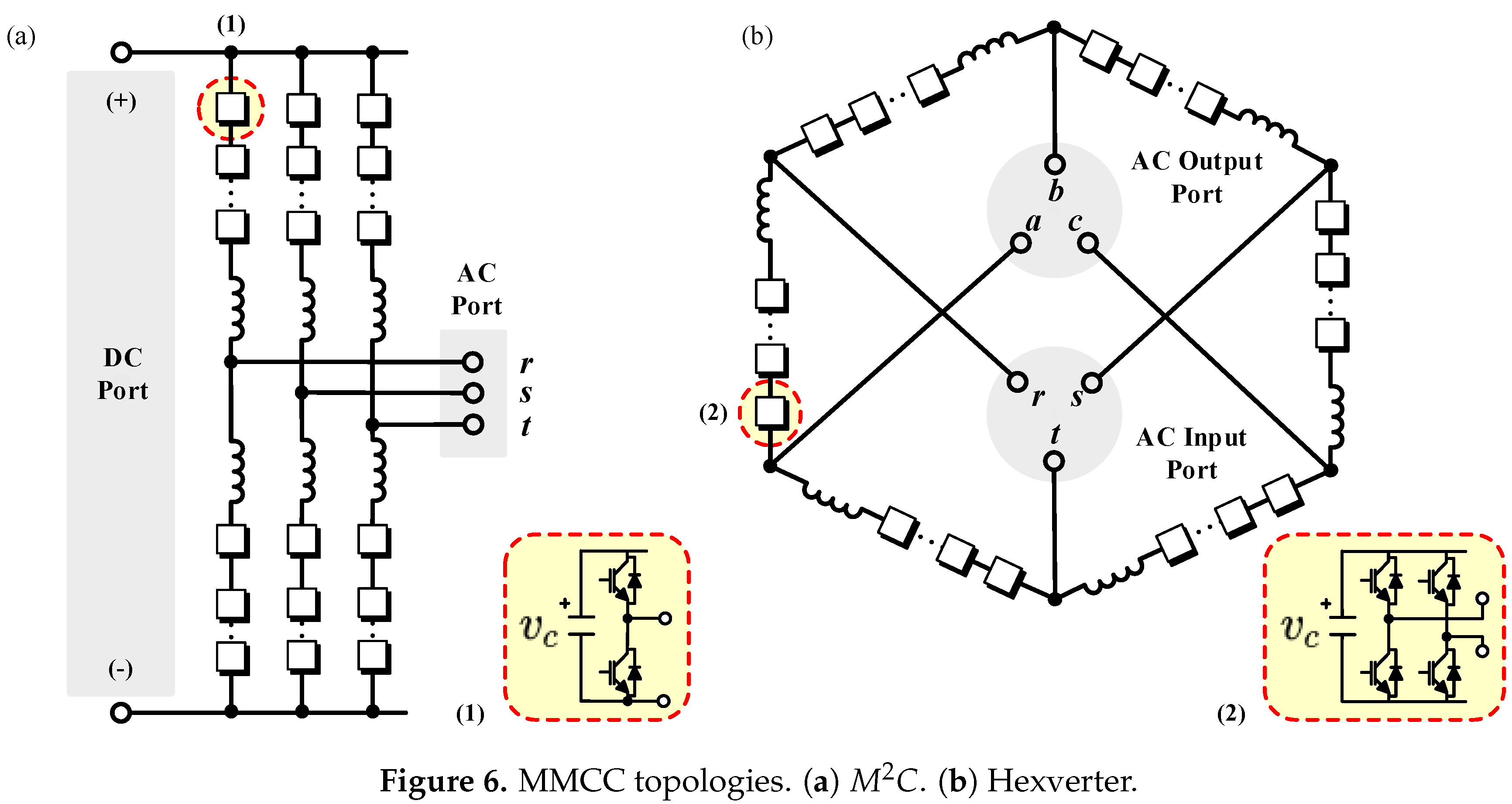
3. Comparison to Others MMCCs

The M 3 C had been compared to other MMCC topologies, such as the modular multilevel converter ( M 2 C ) in back-to-back configuration, and the Hexverter—the most developed alternatives for AC-to-AC applications [19,20,21].
The M 2 C topology is presented in Figure 6a. This converter is composed of six clusters performing AC-to-DC conversion. Each cluster is built considering the cascaded connection of n half-bridge power-cells and an inductor. If AC-to-AC conversion is required, a back-to-back topology with two M 2 C s can be used [71]. The M 2 C is already a well established methodology for HVDC applications [36] and other applications, such as STATCOMs [4], WECSs [5,6], motor drives [14,15,72] and electric vehicles in the automotive industry [73,74] have been proposed in the literature.
The Hexverter topology is shown in Figure 6b. This converter is composed of six clusters, connected in a hexagonal ring to interconnect two AC ports. Each cluster is composed of a stack of full-bridge power-cells connected in cascade with an inductor.
From the analysis and discussion presented in [19,20,21], a comparison among the M 2 C , Hexverter and M 3 C is summarised in Table 2. It is important to mention that a M 2 C in back-to-back configuration is considered, which means that in fact there are two M 2 C s interconnected by their DC-ports.
To support this comparison, the following parameters are considered for the three converters:
  • Nominal power: 10 MVA.
  • Input-port voltage: 6 kV and 20 Hz.
  • Ouput-port voltage: 6.6 kV and 50 Hz.
  • The power-cells operates at 1.7 kV with a 7 mF capacitance.
The performance indicators are the number of power-cells, the normalised power rating of the semiconductors, the unit capacitance constant (UCC), the operation in DFM (which is defined as operation when the output port of the MMCC is connected to different frequencies AC systems, for instance, during the starting-up of an electrical motor), the operation in EFM (i.e., when the output port of the MMCC is connected to an AC system operating with a similar frequency to that of the input port) and the number of circulating currents that can be used to regulate each converter. Notice that the goodness factor utilised to measure the suitability of each topology in DFM/EFM operation is shown as the labels ranging from - as not advisable up to +++ as very appropriate.
The normalised power rating of the semiconductors is defined in Equation (26) [20]. This index is used to compare semiconductor requirements in different topologies.
S s w = S s m S c o n v = n x y · n s m · V ^ x y · I ^ x y S c o n v
where the number of clusters is denoted by n x y ; the number of semiconductors per power-cell is n s m ; V ^ x y and I ^ x y are the peak values of the cluster voltage and cluster current, respectively; and S c o n v is the nominal power of the converter.
The definition of the UCC index is presented in Equation (27). The UCC is a simile of the inertia J used in electrical machines, and it is defined for MMCCs as the total energy stored in the floating capacitors divided by the power rating [75]. The UCC is regularly used as a dimensioning parameter to compare MMCCs [18,76].
Assuming that all the power-cells have the same capacitance C, and all floating capacitors are charged at the same voltage level, v C , the UCC can be calculated as follows:
U C C = 1 2 C n x y · n · v C 2 S c o n v
where the number of cells is denoted by n.
As shown in Table 2, the back-to-back M 2 C has the lowest semiconductor current rating among the topologies compared in this work, but the highest number of power-cells and UCC index. In general, the back-to-back M 2 C is considered the most suitable solution for EFM operation because in this operational state no mitigation signals are required to control the voltages in the floating capacitors. Consequently, the back-to-back M 2 C has been extensively used in HVDC transmission systems, where is somehow an established technology [9,35,36,37]. On the other hand, the operation of the M 2 C in DFM involves the injection of mitigation signals to keep the regulation in the floating capacitor voltages, resulting in decreased efficiency and an increase of the control complexity for this operating range [14,15,77].
In DFM operation, the Hexverter and the M 3 C are better suited than the M 2 C [8,16] because smaller voltage oscillations are produced at this operating point when the converter (i.e., M 3 C or Hexverter) is feeding an electrical machine with a low back-emf during low-frequency operation. As shown in Table 2, the Hexverter has the highest semiconductor current rating because a compensation power (referred to as adjacent power) is required in this converter [16]. Then, higher circulating currents are needed to mitigate the capacitor voltage oscillations compared to those required in the M 3 C . Additionally, there are some operational points where the injection of common-mode voltage is required to perform balancing control. Nonetheless, the Hexverter presents the lowest number of power-cell requirement because it is composed of just six clusters.
For the EFM operating point, it is worth mentioning that the operation in EFM is challenging for the Hexverter and the M 3 C . Both converters require the injection of mitigating signals to ensure appropriate control of the floating capacitors in EFM [39]. However, the M 3 C is more suitable than the Hexverter in terms of semiconductor ratings and control flexibility for DFM and EFM operation. During DFM, the M 3 C does not require the injection of mitigation signals. On the other hand, the Hexverter requires the injection of a compensation power for balancing and mitigation purposes. Therefore, continuous injection of common-mode voltage and circulating currents are utilised, reducing the efficiency and increasing the built-in ratio. The M 3 C favourably compares to the Hexverter for EFM operation because it has more degrees of freedom and this provides more control flexibility. As shown in Table 2, the M 3 C has four circulating currents which can be manipulated to allow proper EFM operation [39,78]. If the common-mode voltage is considered the M 3 C has a total of up to five degrees of freedom for control purposes which can be used in different operating points.
It is relevant to mention that the comparison presented above strongly depends on the applications being studied, efficiency required, total harmonic distortion allowed in the input/output voltage and current, etc. Different scenarios can lead to different results in the comparison.

M 3 C , M 2 C and Hexverter Advantages and Disadvantages

In this section, some additional comparisons are realised and summarised for the three converters discussed in the previous section. As shown in Table 2, the Hexverter is a suitable converter for applications where the power to volume density is critical, mainly because it operates with fewer power-cells in comparison with the M 3 C and the M 2 C . Nonetheless, as aforementioned, the reduced number of cells decreases the available degrees of freedom in the converter, reducing the control flexibility of the topology [16,20]. Regarding applications, this converter has been proposed for WECSs and low-frequency AC transmission. However, the Hexverter is not recommended for off-shore WECSs or any critical application due to its limited fault-tolerance.
Nowadays, the most established MMCC topology is the M 2 C , also referred to as the Marquardt converter [2]. This converter is considered a well-established technology with commercial solutions in the market for HVDC transmission and motor-drive applications. The power-cells in the M 2 C are usually half-bridges. Then a reduced number of semiconductors is required in comparison with full-bridge power-cell-based topologies such as the Hexverter and M 3 C . Nevertheless, the application of the M 3 C in motor drives is challenging since high voltage fluctuations appear in the floating capacitor voltages [14,15] during DFM operation.
Finally, Table 3 summarises the main characteristics of the M 3 C . This converter has the advantages of high controllability with several degrees of freedom and fault-tolerance when compared with the M 3 C and Hexverter [27]. For instance, it has been demonstrated that when a cluster of the M 3 C faults, the converter can still operate as a Hexverter, reducing its power conversion ratio [29]. In this manner, the M 3 C is a suitable topology for off-shore WECSs, where the maintenance and fault tolerance play important roles. The application of the M 3 C for drive applications and low-frequency AC (LFAC) transmission systems has also been validated [8,79]. However, the drawbacks of this topology are its high component count, and the difficulties in EFM operation due to the high capacitor voltage fluctuations produced at this operating point.

4. Applications

The M 3 C have been indicated as an appropriate alternative for high-power AC-to-AC applications such as wind energy conversion systems, variable-speed drives, FACTS applications and low-frequency AC transmission. The M 3 C is a good alternative for WECSs and drive applications, because of its appropriate performance in low-frequency operation. Moreover the M 3 C has all the advantages of modular multilever converters, including modularity, scability, fault redundancy, etc. In consequence, there are many areas such as FACTs and LFAC transmission where the M 3 C is considered a suitable candidate. This is discussed in the next subsections where simulations and experimental results are provided to validate the applications.

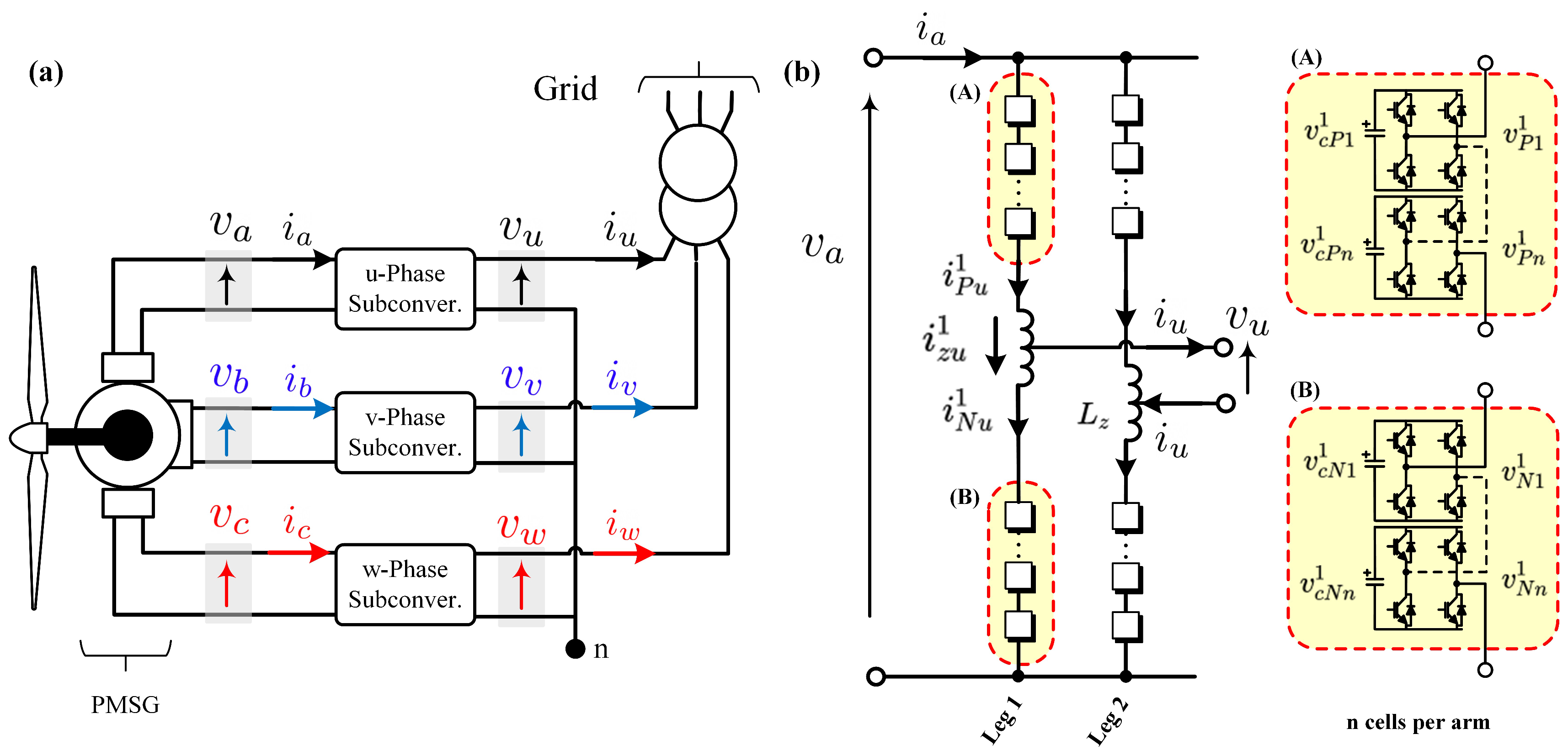
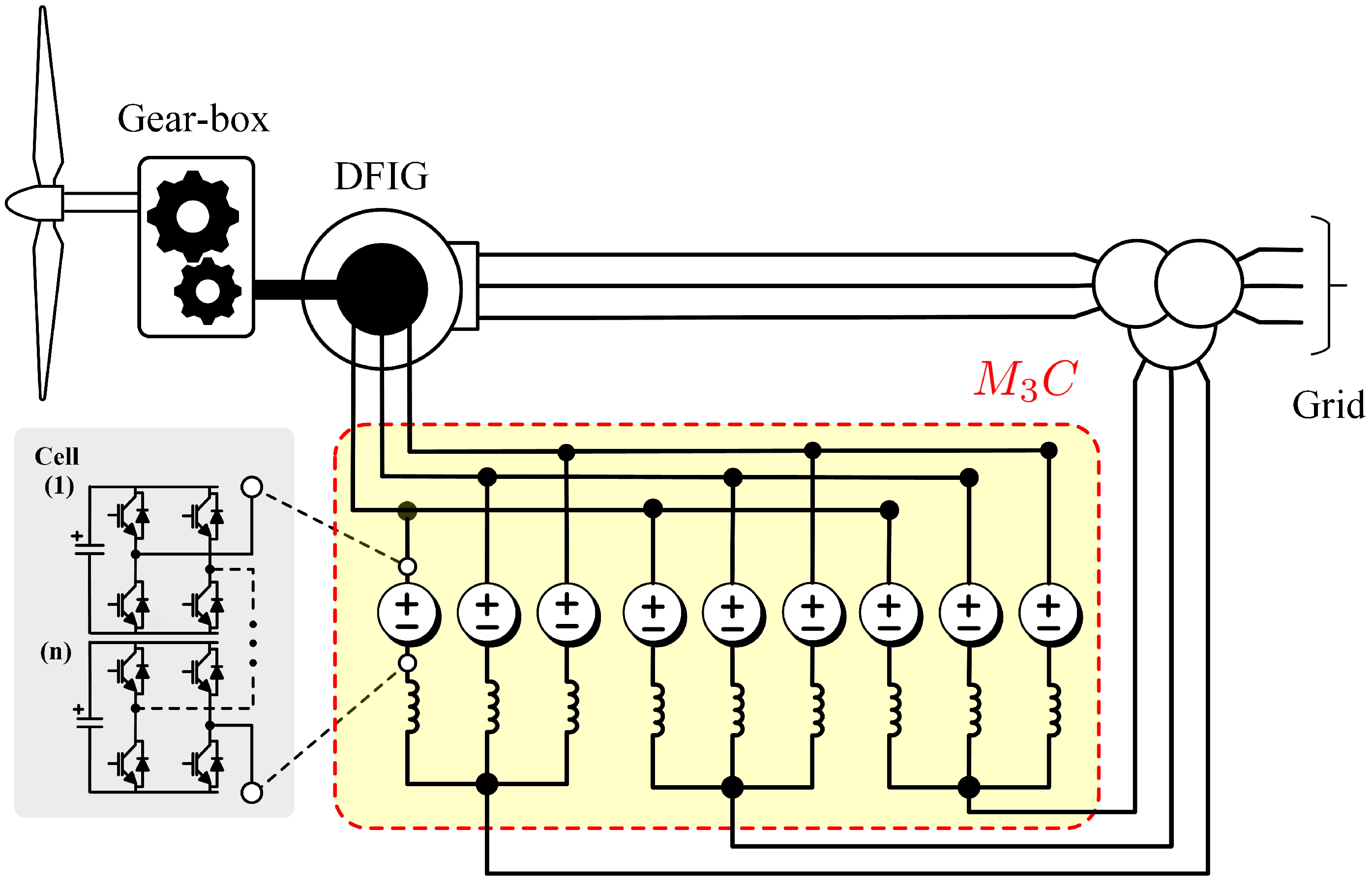
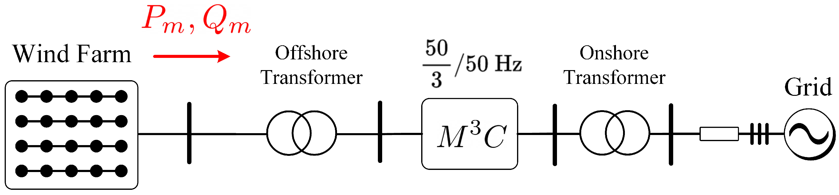
4.1. Wind Energy Conversion Systems

Wind energy has grown at a faster rate than all the other renewable energy sources in recent times. The wind power production capacity for the whole world increased from 17.4 GW in 2000 to about 600 GW at the end of 2018. In 2018 though, 50.1 GW of wind power capacity was installed in the world (60 GW in 2017) [80].
A significant part of the wind power capacity is installed offshore, due to the presence of higher wind energy, the lower environmental impact, the lack of suitable onshore sites available, etc. For offshore applications, high-power wind turbines can reduce the cost structure of offshore WECSs [81]. Accordingly, the power rate and rotor diameters of a single WECS have increased to 12 MW and 220 m in 2020. For instance, the Haliade-X, a 12 MW WECS produced by GE (Boston, MA, USA), has a rotor diameter of 220 m [82].
Most of the existent wind turbines are composed of low-voltage power converters, usually implemented using back-to-back voltage source inverters based on 1700 V insulated gate bipolar transistors (IGBTs), which are connected to 690 V low-voltage bars. Therefore, for multi-MW wind turbines, high currents are produced at the WECSs’ outputs. To overcome this problem, medium-voltage converters have been proposed for this task [19,22,23,27,83,84,85].
The M 3 C has also been proposed for wind energy applications since the early work of Erickson (see [22,23]) but also in more recent papers [19,54,86,87,88,89,90,91,92]. In these works, the M 3 C is proposed for the interconnection of the electrical generator, of a large-power WECS, to the grid. This is shown in Figure 7.
The M 3 C is considered a good alternative with which to control high-power, variable-speed generators and motors. As aforementioned, some of the main advantages are simple scalability in the voltage range; good fault-ride-through performance [27,88]; simplicity to provide converter fault-redundancy; and good performance when the machine is operating at nominal torque and low rotational speed [8,21]. As discussed before, in the latter case, the frequency applied to the stator of the electrical machine is relatively low, but also the machine back-emf is usually small. Hence, (unlike the M 2 C ) the voltage fluctuations in the capacitors, at this operating point, are relatively simple to control, even without the utilisation of mitigation currents [27].
The operation at high-power with similar or equal frequencies at the input and output ports of the M 3 C is challenging. Some overrating of the converter (to accommodate for the required circulating currents and common-mode voltages) could be necessary to achieve good stable performance (see [39]). Otherwise, a M 3 C -based WECS would likely have to be designed to achieve nominal power output when the machine operating frequency is ≈10% below the grid-frequency. However, as discussed in [93], for high-power, direct-drive Permanent Magnet Synchronous Generator (PMSG) based WECS, nominal output frequencies of around 15 Hz could be obtained in the machine side of the topology depicted in Figure 7. Therefore, in this case the frequencies | f m ± f g | (with f g as the grid frequency and f m as the machine frequency) have relatively large values for the whole operating range, and the voltage oscillations produced are relatively simple to control if appropriate voltage and current capability margins are available at the M 3 C .
The application of an MMCC, similar to the M 3 C , has also been reported for the control of multi-channel generators in [90] (see Figure 8). Multi-channels generators have been proposed in [94] to improve fault redundancy. Therefore, if a fault is produced in one of the phases, e.g., because of a short circuit in the winding or a single power converter failure, then the healthy phases can be used to supply power to the grid. In this case, the generator is derated by a factor of ( n 1 ) / n , where n is the number of windings. Alternatively, the generator could be designed to maintain nominal power operation even in the event of one phase failure.
The topology depicted in Figure 8b has also been proposed to interlink two single-phase AC systems directly. In [95], the single-phase M 3 C illustrated in Figure 8b was utilised as a power conditioner which is particularly appropriate for Scott traction systems. Besides, as shown in Figure 8a, three identical single-phase M 3 C s were proposed in [90] to interconnect a three-phase open-winding PMSG with six lead terminals to a step-up line-frequency transformer for grid connection. The terminals of the resulting MMCC topology are connected in a star connection, as shown in Figure 8a, producing the primary winding voltages required to feed the power transformer.
The M 3 C could also be used for DFIG-based WECs. This is shown in Figure 9 and further discussed in [86,91]. It is claimed that the M 3 C improves the low voltage ride-through (LVRT) performance owing to the capability of the M 3 C to impose a larger voltage in the DFIG rotor, maintaining current control and avoiding the utilisation of crowbars to demagnetise the machine. In the case crowbars are still required, it is claimed in [91] that a smaller reduced-power device would be necessary.
Only simulation results for a three-phase symmetric fault are presented in [91]. The performance of the proposed topology for asymmetric faults has neither been discussed nor analysed.

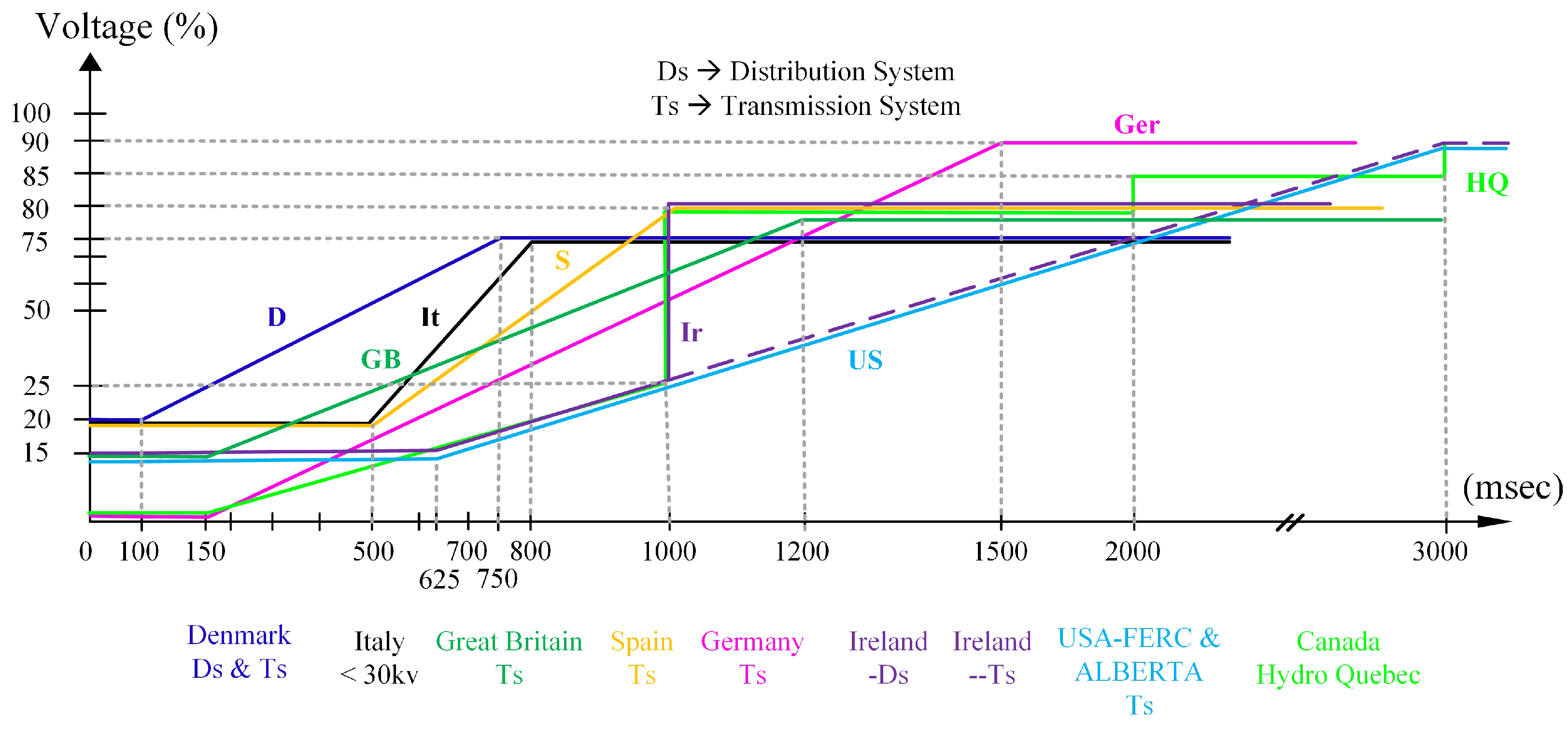
4.2. Low-Voltage Ride-Through Control Considering Permanent Magnet Machines

To avoid stability issues in power systems with extensive penetration of wind energy systems, the transmission system operators are enforcing stringent grid-codes to prevent the disconnection of large WECSs during low-voltage faults in the grid. A summary of grid-codes for several countries is reported in [96,97], and some grid-code requirements are illustrated in Figure 10. Notice that the allowed depth and duration of the voltage fault, before disconnection of the WECS, might vary from country to country. As stated in [96], the time-length where WECSs have to remain connected in case of a fault might last from milliseconds up to minutes. When the voltage at the point of common connection is operating above the line of the respective country’s grid-code, the WECS must maintain connected. Otherwise, it can be disconnected.
The control systems required for grid-code compliance of a M 3 C -based WECS utilising a PMSG have been partially investigated in [27,87,88,89,98]. Experimental results for LVRT performance are presented in [27]. In this work an experimental system composed of 27 full-bridge power-cells is used to validate the proposed LVRT algorithm which is designed to avoid second order (100 Hz) power oscillations in the floating capacitors of the converters. The performance of the proposed LVRT algorithm was tested for several conditions, including zero voltage ride-through (ZVRT) (see [96] and Figure 10). Some of the experimental results obtained in [27] are briefly discussed below.
The experimental system used in [27] is shown in Figure 11 and it considers a 27 power-cell M 3 C prototype. Note that the diagram of this setup is presented in Figure 5. The grid and the machine were emulated using programmable power supplies, which were used to analyse the performance of the M 3 C for LVRT control. Using the grid-side programmable power supply, a symmetrical dip type A fault (a three-phase short circuit) was emulated. The experimental results are shown in Figure 12. For this test, the three grid voltages were reduced to 30% of their voltage magnitudes at t ≈ 0.2 s. Notice that Figure 12a,b utilises a different time scale when compared to Figure 12c–e. Immediately after the fault was applied, the active power current (grid-side of the M 3 C ) was regulated at 0 A, and the reactive power current was regulated to 50 % of the nominal current to provide support for the grid-voltage recovery (see Figure 12e). Notice that during the fault, the capacitor voltages are well regulated in the prototype with a ripple component below 5 % of the reference value.
The performance of the proposed LVRT control has also been experimentally tested considering a dip type C fault (a short circuit between two phases), and the experimental results are shown in Figure 13. In this case, the voltage magnitudes in phases b and c decreased to 50% of their nominal values (see Figure 13a). For this test, the current control system regulated the grid current supplied by the M 3 C to produce an active power without double frequency oscillations (see [99,100]), as depicted in Figure 13d. However, double frequency oscillation could not be eliminated from the reactive power, as shown in Figure 13d. Finally, the instantaneous active power oscillation in the M 3 C can have double frequency oscillations, and this can produce more oscillations in the 27 floating capacitor voltages, as shown in Figure 13c.

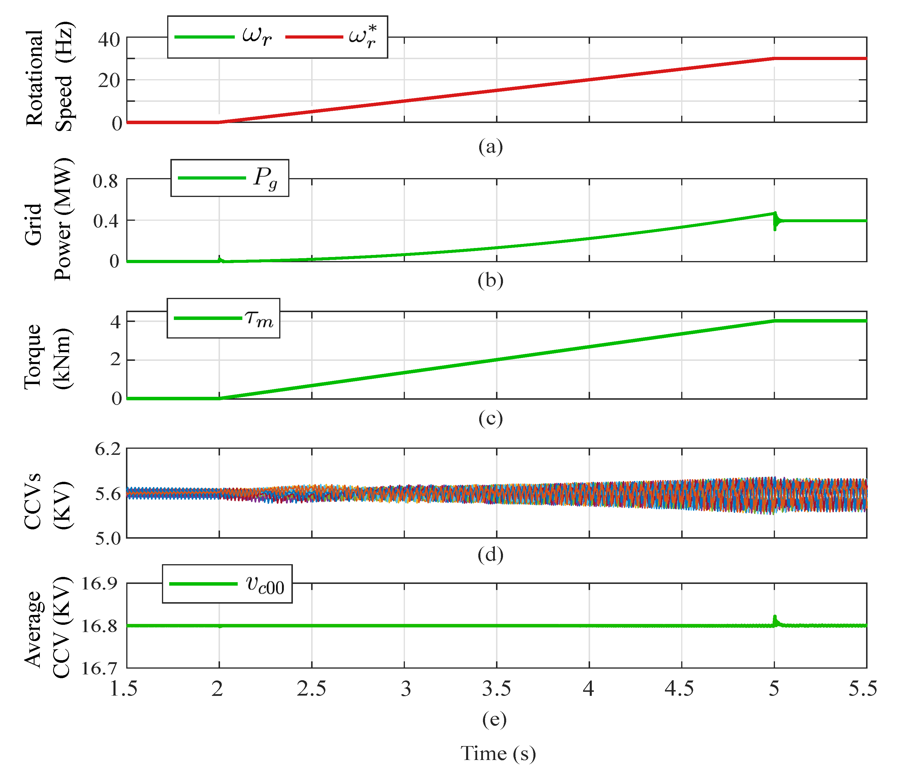
4.3. Variable-Speed Drives

The market for medium-voltage motor drives has been expanding rapidly with new improved solutions being provided to the market [101]. A good discussion of the power converters typically used in this voltage range is provided in [26,102].
Nowadays, the three-level neutral point clamped (NPC) converter is the multilevel topology most employed for medium-voltage applications [103]. The NPC converter was introduced in 1979 [26]), and it has been used in several applications, including the Japanese high-speed train “Shinkasen”. Another topology with commercial applications is the multilevel converter based on flying capacitors [104]. Alstom Power and Grid offer this converter as a 4-level flying capacitor inverter for medium voltage drive solutions. A significant advance in the development of modular multilevel converters for medium voltage drives was the development of the cascaded H-bridge (CHB) drive produced by Robicon Corporation, now part of Siemens (Munich, Germany). This converter is based on the cascade connection of full-bridges (see [105]), each of which are controlled using PWM. The main disadvantage of the Robicon converter is that a bulky multi winding transformer is required. However, this converter has modularity; i.e., “H” bridges can be added to the topology to increase the output voltage level and power, and can be efficiently designed to provide fault redundancy. This converter is considered a precursor of the modern modular multilevel topologies utilised in medium voltage drives.
In 2003, Marquardt introduced a new converter topology named the modular multilevel converter [1,2] or the Marquartd converter. Even though the main applications of this topology are related to HVDC transmission [26], since 2016 the M 2 C topology has been offered by Benshaw [12] and Siemens [13] as a commercial solution for medium-voltage drives. Other modular multilevel topologies proposed for medium voltage drives are the M 3 C and the Hexverter.
The comparison between the Hexverter, the back-to-back M 2 C and the M 3 C previously presented in Table 1 is further expanded in this section to include more aspects related to the control of electrical drives. Other topologies, as the series-parallel MMCC, also referred to as π -MMC, (see [106]) have not been included in this comparison because they have not been investigated for drive applications. Therefore, in Table 4, some topologies are compared in terms of control flexibility and degrees of freedom available for control purposes. Additionally, the topologies of the power-cells are considered to distinguish two types of M 2 C . In motor-drive applications, the M 2 C can be implemented using half-bridge cells, or it can be composed of a mixture of half-bridge and full-bridge power-cells, the latter topology being referred as a hybrid M 2 C [107,108].
As discussed previously in this work, the M 3 C is more suitable for low-frequency, high-torque operation of drives when compared to the M 2 C . As discussed in [14,15], during DFM operation, high voltages oscillations are produced in the M 2 C which are proportional to the magnitude of the machine stator currents. Therefore, the M 2 C converter is considered more suitable for rotational loads where the required electrical torque is quadratic with respect to the rotational speed [8,21,26]. For control purposes, the M 3 C has five variables which can be utilised as degrees of freedom to balance the energy in the converter and mitigate large voltage oscillations in the capacitors. These are four circulating currents and the common-mode voltage, and depending on the drive design and/or operating point of the drive, the common-mode voltage may be not required to operate the converter.
As the M 3 C is an AC-to-AC topology, a fairer comparison is realised when this power converter is compared to the back-to-to back M 2 C and the hybrid back-to-back M 2 C . As mentioned, the back-to-to back M 2 C has been extensively studied. On the other hand, the later topology has been recently reported and discussed in [107,108]. One of the main benefits of the back-to-back hybrid M 2 C is the capacity to reduce the DC-link voltage, which has some advantages for the low-speed operation of variable-speed drives (see [108]). The hybrid back-to-back M 2 C has more degrees of freedom in total (four circulating currents, common-mode voltage(s) and variable DC-link voltage). Nevertheless, the circulating currents are controlled separately in the M 2 C ; i.e., two circulating currents are utilised on the machine-side and two circulating currents for the grid-side converter. Moreover, one of the well-known problems of the hybrid M 2 C is the large circulating current required in the grid-side M 2 C when the DC-link voltage is very low (see [107,108,109]). The comparison between the regular back-to-back M 2 C and the M 3 C for variable-speed drives has been realised in various publications (see [19,20]. However, it is important to mention that the performance of the hybrid back-to-back M 2 C has not been thoroughly studied yet, and it is difficult to adequately compare the performance of an M 3 C to the hybrid back-to-back M 2 C in terms of the attributes depicted in Table 2 and Table 4.
Analysing Table 2, it is confirmed that the M 3 C has an excellent performance when operating a drive at low rotational speed—better than those obtained using the back to back M 2 C and the Hexverter [16,20,48]. The main problem of the M 3 C to control motors and generators is during operation with equal (or very similar) frequency in the input and output ports. Solutions have been reported in [39,58,60,77,78]. The most common approach is to operate with a complementary power factor at the input and output ports (i.e., Q g = Q m ) and synthesise a voltage of the same magnitude at the input and machine sides (i.e., V g = V m ) (see [39,78]). Using these conditions, the floating capacitor oscillations are reduced. However, when this strategy is implemented using an open-loop scheme, any deviation from the conditions Q g = Q m and V g = V m may produce large capacitor voltage oscillations and instability. Alternatively, EFM operation can be achieved by using common-mode voltage and circulating currents. The advantage is that this approach relies on a closed-loop control system to regulate the voltage oscillations in the capacitors. The disadvantages are that it is necessary to increase the rating of the M 3 C because of the additional capacitor voltage and cluster currents required for the common-mode voltage and circulating currents.
Simulation and experimental results for an M 3 C -based drive are discussed in this section. The simulation results of a 10 MW M 3 C based drive have been obtained using PLECS software (Plexim, Zurich, Switzerland). The main parameters of the M 3 C and induction machine (IM) are provided in Table 5. More details are in [31,110].
The speed profile used in these tests is shown in Figure 14a, and it was regulated to start at 0 Hz and reach 30 Hz. Regardless of the machine frequency, proper balancing of the floating capacitor voltages was achieved, as shown in Figure 14b. In this case, as presented in Figure 14c, a lineal torque-speed load was considered. Finally, Figure 14d,e confirms that the total voltages available in each cluster, referred to as CCVs, are properly regulated.
The experimental results have been obtained considering the experimental setup depicted in Figure 11a. Results for open-loop control are shown in Figure 15 using the modelling and control strategies discussed in [39]. In this approach, the CCVs are transformed to the Σ Δ double– α β γ frame representing unbalanced voltages. As indicated in [92], the CCVs have to be regulated at 0 V in Σ Δ double– α β γ frame to ensure equal voltage distribution in all the clusters of the M 3 C . In the first test, the performance of the control system was tested considering a small frequency difference between the input and output ports (at the beginning of the test) up to equal frequency operation. First, the input port frequency was f m = 48 Hz and the output port frequency was set to f g = 50 Hz. Consequently, voltage fluctuations of 2 Hz appeared in some of the CCVs, as shown in Figure 15b. The remaining CCVs were well regulated, as shown in Figure 15b,c. In this approach, the power oscillations are not directly controlled using closed-loop control. Therefore, the system can hardly respond to changes in the operating points, incorrect estimations of the reactive powers, etc. Consequently, in an experimental implementation, it is difficult to operate at equal frequencies (open-loop control) even when it is theoretically possible. This is further demonstrated by the experimental results shown in Figure 15d, where the performance for a step-change from 48 Hz to 50 Hz is depicted. In this case, the control system is not able to regulate the capacitor voltage oscillations, and some of the floating capacitors drift away from the reference value.
In Figure 16, the closed-loop CCV control system proposed in [39] is utilised to regulate the capacitor voltage oscillations during EFM. For this test the input/output port grid frequencies were set to 50 Hz with different power factor demands: The output port grid operated with −3.3 kW/0 kVAr, and the input side with 3.3 kW/2.1 kVar; the reactive power magnitude in the input side was regulated to achieve nominal current amplitude in the input side. The regulation of the CCVs was performed by using a combination of circulating currents and common-mode voltage.As illustrated in Figure 16a, the M 3 C capacitor voltages are well regulated at v c * = 150 V even when the input and output frequencies are equal. Moreover, the CCV imbalances are adequately regulated, as shown in Figure 16b,c. Experimental results from oscilloscope captures are presented in Figure 16d,e. The floating capacitor voltage of a single power-cell, a generic cluster voltage v x y and phase-to-phase voltages of the input and output port are displayed in Figure 16e. Finally, the three-phase input currents are presented in Figure 16f.

4.4. FACTS

In the last rew decades and considering the widespread use of electronic non-linear load and power converters, several power quality problems, such as voltage swells and sags and harmonic distortion, have expanded in power grids. These problems have enforced the use and evolution of FACTS devices. The integration of FACT devices is being used to improve power grid dynamic and static behaviours, providing higher operating flexibility and better use of the power system infrastructure [111].
Considering their connection to the power system, FACTSs can be classified as shunts, series and combined devices [112]. Shunt FACTS, such as the STATCOM and the Static Var Compensator (SVC), are generally used to provide voltage and power factor compensation [113]. Series FACTS, such as the series static synchronous compensator (SSSC), are used to provide impedance line control and transmission line relief [114]. Finally, combined FACTS such as the Unified Power Flow Controller (UPFC) are hybrid or combined control FACTS with the capability of bidirectional power flow control; voltage and reactive power control; and the capability to increase the steady and dynamic stability of power grids [113,114].
For high-power applications, thyristor-based FACTS are the preferred technology due to their reliability and the higher capability of the semiconductors. However, even when thyristor-based FACTS are reliable, they have significant disadvantages, such as low power factor, limited regulation capability, limited redundancy, high harmonic distortion, restricted operation in cases of faults and high output ripple. Due to these disadvantages, the development of FACT devices based on MMCCs has gained attention as a proper and feasible alternative in the industrial market [115,116,117].
Examples of the use of MMCCs in FACTS applications are reported in [59,64,118]. For instance, the connection of the M 3 C to provide UPFC capabilities is illustrated in Figure 17a [59,64,118]. In this case the M 3 C is connected to operate as a shunt FACTS at the input-port, and as a series FACTS at the output port. As both ports have the same frequency, the M 3 C must be controlled to provide precise EFM operation.
In [118], a direct power control of an M 3 C for FACTS applications is proposed. This paper studies a control system implemented in the Σ Δ double– α β γ coordinates to regulate the floating capacitor voltages, whereas the converter provides functions of a series connected FACTS. Recently, a control strategy implemented on the Σ Δ double– α β γ frame was proposed for a M 3 C -based UPFC, considering shunt and series FACTS behaviour, as discussed in [59]. The control of the input port of the M 3 C regulates the average voltage, whereas the output port control is focused on power flow compensation. The proposed vector control scheme was successfully validated through simulation and experimental results with a 5kVA M 3 C prototype composed of 27 power-cells. Some of the experimental results provided in [59] are summarised in Figure 17b,c. The active and reactive powers of the input and output ports are separately regulated. To corroborate the response of the overall system, step changes in the active/reactive power components are used. As shown in Figure 17c, the capacitor voltages remain regulated at 150 V during the step variation in the power demand. The active/reactive power injection/demand of the input/output port are depicted in Figure 17b.
Due to the control flexibility of the M 3 C , an extension to the control capabilities of a traditional UPFC can be obtained. In [64], the M 3 C is proposed as a unified power quality conditioner (UPQC). The UPQC has the same functionalities of a UPFC, i.e., shunt and series FACTS compensation, plus active filter capabilities for harmonic mitigation.

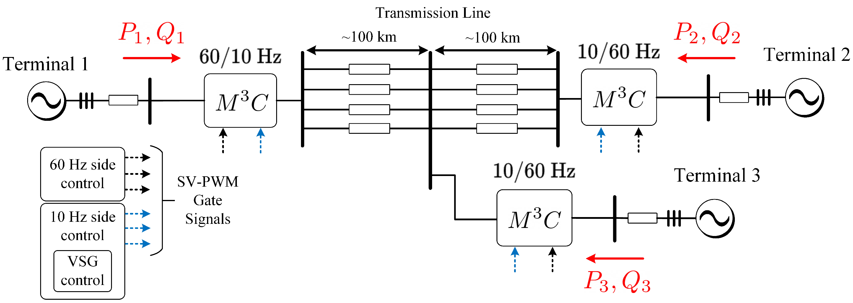
4.5. Low-Frequency AC Transmission Systems

LFAC transmission systems, also referred to as fractional frequency transmission systems, have been proposed as an alternative to conventional AC and DC transmission systems. Typically, LFAC transmission is performed using a 1–20 Hz frequency range [119]. LFAC systems have some advantages compared to 50/60 Hz and HVDC transmission systems. Firstly, because of a reduced capacitive current component, LFAC systems have an increased use of the power capability of the transmission cables, in comparison to standard 50 Hz or 60 Hz AC transmission systems, thereby achieving a longer length of the AC transmission lines [120]. Secondly, the investment cost of an LFAC transmission system is reduced in comparison to that required for HVDC transmission. Moreover, the fault protection requirements in LFAC are much more straightforward to implement than those required in HVDC, due to the zero-crossing nature of the AC current [121].
As for the advantages of MMCC topologies, for the HVDC connection of wind parks, the M 2 C is considered the state-of-the-art technology in Europe [121]. Consequently, AC-to-AC MMCCs can be appropriate solutions for LFAC transmission systems [122]. Several research proposals have discussed the control of the M 3 C in this application [79,123,124,125,126,127]. The application of the M 3 C in the power system shown in Figure 18 is presented in [79], where an Space Vector Modulation (SVM) control approach is proposed. As discussed in [27], SVM control is only feasible when a small number of power-cells is considered. Therefore, the results in [79], which are obtained with a 1-power-cell per cluster M 3 C , are not an adequate reference for a real case application (with more than two cells per cluster). A similar approach is presented in [124].
An M 3 C -based multiterminal LFAC system has been proposed in [127]. The electrical system diagram is shown in Figure 19, considering the use of three M 3 C s to perform 10–60 Hz conversion. In [127], a novel control scheme based on a virtual synchronous generator (VSG) scheme for the M 3 C -based LFAC is proposed. In [123,124,125,126,127], the focus is the control of the M 3 C from a power system point of view. Therefore, the converter modelling and control is simplified and just M3C-output power at input/output ports is contemplated. In those proposals, the M 3 C regulation considers just the regulation of the sum of all the floating capacitor voltages. The management of the voltage imbalance in the floating capacitors is not considered. As simulation results are presented, there are not imbalances to control and the operation of the M 3 C for the LFAC systems seems to be appropriate.

5. Trends and Future Research for the M3C

During the last few years, more research efforts related to the M 3 C have produced significant advances in areas such as modelling, control, modulation schemes, new applications, dimensioning and other features. Nevertheless, no companies are commercialising medium- or high-voltage converters based on the M 3 C , mainly due to the high cost, high number of components, control complexity and hardware limitations. Numerous aspects should still be addressed to overcome the main disadvantages of the M 3 C and to extend its utilisation into commercial applications, for instance, those described in Section 4.
The technological improvements of semiconductor devices might contribute to upgrading the cost-effectiveness of the topology, enhancing characteristics such as cost reduction, efficiency, power density, specific power density and operating voltage-power limits. Therefore, further research on dimensioning and fabrication of M 3 C based on high-efficiency, fast semiconductors is required.
The extensive use of measurements and communication channels required to control an M 3 C is still a practical restriction when the number of power-cells is large. When a centralised control platform is used, just one main controller needs to handle a high amount of input-output, to compute the whole control algorithm in one short period and to provide the switching signals to all the devices located in the power-cells. Therefore, an interesting research area is to study the application of distributed control algorithms to divide the computational burden and the required peripherals. Compared to the centralised control, distributed control algorithms can offer advantages in MMCC applications, due to the reduced number of peripherals and lesser computational burden assigned to each controller. This research field is relatively new for MMCCs, and its benefits include the easy scalability when more cells are integrated and the enhancement reliability of the converter. The three-stage control structure presented in Figure 4 can be implemented in a multi-DSP-based digital control system architecture, as proposed in [53]. The proposals for the M 2 C [128], can be expanded and adapted to the M 3 C case.
Another interesting topic for future research would be to introduce fault tolerance capability in the M 3 C . At the moment, just a few works have studied the continuous operation during this contingency [34,48]. The impact of the loss of power-cells or even a complete cluster must be analysed and considered to design the control of the floating capacitor voltages, circulating currents and modulation schemes. The fault capability includes two main goals: the fault identification and online reconfiguration of the control references for the specific modified structure. For power-cell faults, the n 1 design criteria shown in Equation (19) can be incorporated to provide voltage margin under power-cell faults. For cluster faults, there are some research works presenting the operation of the M 3 C when a full cluster is disconnected. In [34], the failed cluster is bypassed along to other two clusters, and the M 3 C is reconfigured as a Hexverter. The output power of the M 3 C is reduced to approximately 70 % of its nominal rate.
The ride-through capability of the M 3 C could be further analysed under grid-voltage perturbations. As indicated in Equation (13), the M 3 C has an inherent voltage margin as the minimum CCV is composed by the sum of the input and output voltages (see Equation (13)). When a grid-voltage dip is produced, the available voltage in the CCVs can be used to enhance the fault-ride-through performance of the M 3 C . The LVRT behaviour of the M 3 C has been highlighted [98]. Still, there are other grid-voltage perturbations such as symmetrical and unsymmetrical grid-voltage dips, harmonic contamination and flicker that could be matters for new investigations. The compensation of harmonic distortion, or more generally, the use of the M 3 C for improvement of the quality of the overall power system has not been well investigated.
Regarding applications, more research in the following fields could be required:
  • Ongoing work on motor-drive applications
    The use of the M 3 C in medium-voltage and high-voltage motor-drive applications is foreseen to be expanded. The voltage extensibility of the M 3 C can be advantageously used to connect electrical machines directly to medium-voltage grids, and then, bulky step-up transformers can be avoided.
    However, a critical drawback of the M 3 C in drive applications is to achieve EFM operation without requiring a large over-rating of the converter to provide circulating currents or to accommodate relatively large common-mode voltages. Thus, the development of enhanced mitigation techniques for the regulation of the oscillations in EFM is required. High-performance control strategies, with high bandwidth, reduced circulating current and reduced common-mode voltage references must be further developed [28,58].
  • Ongoing work on WECS applications
    There are still research challenges related to reducing both the volume and weight of the passive components of high-power WECSs, including transformers, inductors and power-cell capacitors typically located in the nacelle. Then, the optimisation of the passive components of the M 3 C , as preliminarily proposed in [7,17,20,69], could be focused in this aim. For this task, other parameters have to be considered, such as size, weight and volume restrictions of the M 3 C . The possible transformerless operation of the M 3 C in large wind turbines could be also exploited.
    Currently, most of the research proposals are based on type IV PMSG-based WECS. However, different generator- M 3 C configurations should be analysed. The benefits of the M 3 C for type III WECSs have been studied but not experimentally verified yet. Moreover, other generators, such as the superconducting synchronous generator, can be interfaced to the grid using the M 3 C , reaching power ratios of up to 20 MW [81]. As discussed in this paper, applications of the single phase matrix converter for multi-winding generators are also feasible and can be further studied.
    As the participation of wind energy in power systems increases, it is very likely that more stringent grid-code requirements for WECSs will be used in the coming years. Therefore, M 3 C based WECSs should be able to provide new grid-supporting functionalities, and issues such as fault ride-through requirements would have significant impacts on the design and operation of modern WECSs. Fault-ride-through strategies such as that presented in [27] must be expanded to provide zero-voltage and over-voltage ride-through, alongside new functionalities to provide ancillary services, such as frequency support, short-circuit power level, voltage variations, flicker and harmonic mitigation.
  • LFAC Transmission
    The research revised in this paper shows that promissory applications of the M 3 C in LFAC transmission systems are possible. However, there is still work to be realised on dimensioning and control of M 3 C based LFAC systems. On the one hand, the M 3 C can be used to connect an LFAC system to a 50/60 Hz grid. In this case, the difference among the input and output port frequencies is relatively high, and the capacitor of the power-cells can be designed using a small capacitance value (see Equation (24)). Moreover, the regulation of the voltages in the floating capacitors can be performed using circulating currents of reduced magnitudes, without the requirement of injecting common-mode voltages. Therefore, the cost-effectiveness of the topology is increased by a compact design of the passive components of the M 3 C . Nevertheless, in this case, hundreds of kilovolts must be handle by the converter, and then efficient power-cell voltage balancing algorithms must be developed. The current methods are not feasible or do not consider the balancing of the voltages within a cluster when the number of power-cells is large [125,126,127].
  • Other applications
    Regarding new applications, the M 3 C could be successfully applied to several industrial processes requiring high-power AC-to-AC conversion. The first possible future application of the M 3 C is related to new high-power motor-drive applications requiring high torque at zero or low-speed operation. Some of these applications are related to conveyors, kilns, mills and extruders.
    Other applications of the M 3 C are related to solid-state transformers. In this case, it would be possible to connect a low-frequency AC port to a medium-frequency AC port. Additionally, as proposed in [56], a single M 3 C -subconverter can be used with the same purpose of connecting a three-phase, low-frequency and medium-voltage AC port to a single-phase, medium-frequency and low-voltage port. One of the major advantages of using the M 3 C in such applications is that the M 3 C can be designed to step-up or step-down the voltage. Additionally, low-capacitance power-cell capacitors are required due to the medium frequency of one of the port. This implies that the difference between the input and the output port frequencies is high, and then small voltage oscillations are generated. Consequently, low circulating currents are required for the regulation of the floating capacitor voltages. Nonetheless, the solid-state transformer operation of the M 3 C has a significant challenge related to the modulation techniques—synthesising the medium frequency voltage at the output.
The benefits of the M 3 C can be applied in FACTS, as presented in Section 4.4. Besides FACTS and UPFC applications, the M 3 C could be used as a unified power quality conditioner. In this case, the M 3 C can provide UPFC series and shunt compensation at the same time as active filtering of harmonic contamination is performed [118]. Finally, low-voltage AC-to-AC applications can also obtain benefits from the M 3 C , mainly when power quality and power density benefits outweigh cost restrictions.
As discussed in this section, several applications can be fitted to expand the use of the M 3 C . Consequently, further research will play a major role in making the M 3 C an industrial power converter. It is expected that the information provided in this paper will encourage power electronics engineers and scientists to carry out further research on the M 3 C .

6. Conclusions

In this paper, a detailed review of the state-of-the-art of the M 3 C applications has been presented. A topology description, comparisons with other MMCC topologies and revision of the proposed applications are presented.
The M 3 C is a relatively new power converter topology proposed as a future technological solution for high-power AC-to-AC applications. However, its inherent control and hardware complexity, plus the newness of the topology, are the main reasons why there are just about six research groups (see Table 1) which have succeeded in realising experimental validation of control strategies related to the M 3 C . Nonetheless, lots of new research proposals, validated using simulation work, are discussed.
To compare the M 3 C with other topologies, the M 2 C , the back to back M 2 C , the hybrid M 2 C and the Hexverter have been briefly discussed in this work. A comparison between these topologies and the M 3 C indicates that the former is the best suited alternative for low-speed, low-frequency operation of drives because much-reduced mitigation currents and common-mode voltages are required for regulating the voltage oscillations in the floating capacitors. In DFM, the M 3 C has some advantages over both the M 2 C and Hexverter because common-mode voltage is not required and the magnitudes of the necessary circulating currents are smaller.
Due to the aforementioned advantages, the M 3 C has been widely studied for high-power applications such as WECSs and motor drives. To support the pertinence of the M 3 C in these applications, simulation and experimental results have been analysed in this paper. In WECS, the main advantages of the M 3 C are related to a better power density of the topology, leading to weight and size reductions. Moreover, the high control flexibility of the converter allows some simplicity to fulfil grid-code requirements such as LVRT.
For motor-drive systems, the M 3 C has been highlighted as an appropriate solution for low-speed and high-torque applications such as conveyors and extruders. One exciting opportunity is the use of the M 3 C as a replacement of line-commutated cycloconverters, which has been highly recommended by several publications.
Additionally, the application of the M 3 C in LFAC transmission systems is promissory. In this case, DFM operation is involved due to the fractional frequency of the LFAC grid. Then, small capacitor voltage oscillations are produced, yielding simplified control requirements and compact dimensions of the converter.
As highlighted in this article, the technological development of the M 3 C is still in an early stage, with experimental assessments being performed in downscaled laboratory environments. Therefore, it is still necessary to demonstrate and validate the effectiveness of this technology under full-power and operational-environment applications. In this regard, further research is still needed to achieve a higher maturity level of the M 3 C and reduce the gap between the current academic work and the requirements of industrial applications.

Author Contributions

M.D. and R.C.D. worked on the conceptualisation and methodology. A.M., E.I. and M.U. supported the state-of-the-art revision and helped to edit the paper. A.M and M.E. helped to compare control strategies. R.C., F.R. and P.W. provided supervision on all the stages of this research work. All authors have read and agreed to the published version of the manuscript.

Funding

This work was funded by the Agencia Nacional de Investigación y Desarrollo (ANID) of Chile, under projects Fondecyt 11191163, Fondecyt 1180879, Fondecyt 11190852 ANID Basal FB0008 and Fondef ID19I10370. Additionally, the support provided by the University of Santiago through project Dicyt 091813DD is recognised.

Conflicts of Interest

The authors declare no conflict of interest.

References

  1. Marquardt, R.; Lesnicar, A. A new modular voltage source inverter topology. In Proceedings of the European Power Electronics Conference (EPE), Toulouse, France, 3–5 September 2013; pp. 1–10. [Google Scholar]
  2. Marquardt, R. Modular Multilevel Converter: An universal concept for HVDC-Networks and extended DC-bus-applications. In Proceedings of the 2010 International Power Electronics Conference-ECCE Asia, Ankara, Turkey, 21–24 June 2010; pp. 502–507. [Google Scholar]
  3. Pereira, M.; Retzmann, D.; Lottes, J.; Wiesinger, M.; Wong, G. SVC PLUS: An MMC STATCOM for network and grid access applications. In Proceedings of the 2011 IEEE PES Trondheim PowerTech: The Power of Technology for a Sustainable Society, Trondheim, Norway, 19–23 June 2011; pp. 1–5. [Google Scholar]
  4. Akagi, H.; Inoue, S.; Yoshii, T. Control and performance of a transformerless cascade PWM STATCOM with star configuration. IEEE Trans. Ind. Appl. 2007, 43, 1041–1049. [Google Scholar] [CrossRef]
  5. Debnath, S.; Saeedifard, M. A new hybrid modular multilevel converter for grid connection of large wind turbines. IEEE Trans. Sustain. Energy 2013, 4, 1051–1064. [Google Scholar] [CrossRef]
  6. Vidal-Albalate, R.; Beltran, H.; Rolán, A.; Belenguer, E.; Peña, R.; Blasco-Gimenez, R. Analysis of the Performance of MMC under Fault Conditions in HVDC-Based Offshore Wind Farms. IEEE Trans. Power Deliv. 2016, 31, 839–847. [Google Scholar] [CrossRef] [Green Version]
  7. Kolb, J.; Kammerer, F.; Braun, M. Dimensioning and design of a modular multilevel converter for drive applications. In Proceedings of the 15th International Power Electronics and Motion Control Conference and Exposition, Novi Sad, Serbia, 4–6 September 2012. [Google Scholar]
  8. Okazaki, Y.; Kawamura, W.; Hagiwara, M.; Akagi, H.; Ishida, T.; Tsukakoshi, M.; Nakamura, R. Experimental Comparisons Between Modular Multilevel DSCC Inverters and TSBC Converters for Medium-Voltage Motor Drives. IEEE Trans. Power Electron. 2017, 32, 1802–1817. [Google Scholar] [CrossRef]
  9. Debnath, S.; Qin, J.; Bahrani, B.; Saeedifard, M.; Barbosa, P. Operation, control, and applications of the modular multilevel converter: A review. IEEE Trans. Power Electron. 2015, 30, 37–53. [Google Scholar] [CrossRef]
  10. Saeedifard, M.; Iravani, R. Dynamic performance of a modular multilevel back-to-back HVDC system. IEEE Trans. Power Deliv. 2010, 25, 2903–2912. [Google Scholar] [CrossRef]
  11. Glinka, M.; Marquardt, R. A new AC/AC multilevel converter family. IEEE Trans. Ind. Electron. 2005, 52, 662–669. [Google Scholar] [CrossRef]
  12. Benshaw. Medium voltage Variable Frequency Drive M2L 3000 Series. Available online: https://benshaw.com/wp-content/uploads/2020/01/benshaw-m2l-3000-brochure.pdf (accessed on 10 July 2020).
  13. Siemens. Sinamics Perfect Harmony GH150. Available online: https://w3.siemens.com/drives/global/en/converter/mv-drives/Documents/technical-data-sheets/sinamics-perfect-harmony-gh150-technical-data-en.pdf (accessed on 5 July 2020).
  14. Espinoza, M.; Cárdenas, R.; Díaz, M.; Clare, J.C. An Enhanced dq-Based Vector Control System for Modular Multilevel Converters Feeding Variable-Speed Drives. IEEE Trans. Ind. Electron. 2017, 64, 2620–2630. [Google Scholar] [CrossRef]
  15. Espinoza-B, M.; Cárdenas, R.; Clare, J.; Soto-Sanchez, D.; Diaz, M.; Espina, E.; Hackl, C.M. An Integrated Converter and Machine Control System for MMC-Based High-Power Drives. IEEE Trans. Ind. Electron. 2019, 66, 2343–2354. [Google Scholar] [CrossRef]
  16. Karwatzki, D.; Baruschka, L.; Mertens, A. Survey on the Hexverter topology - A modular multilevel AC/AC converter. In Proceedings of the 9th International Conference on Power Electronics—ECCE Asia: “Green World with Power Electronics”, Seoul, Korea, 1–5 June 2015; pp. 1075–1082. [Google Scholar]
  17. Kammerer, F.; Kolb, J.; Braun, M. A novel cascaded vector control scheme for the Modular Multilevel Matrix Converter. In Proceedings of the IECON Proceedings (Industrial Electronics Conference), Victoria, Australia, 7–10 November 2011; pp. 1097–1102. [Google Scholar]
  18. Akagi, H. Classification, terminology, and application of the modular multilevel cascade converter (MMCC). IEEE Trans. Power Electron. 2011, 26, 3119–3130. [Google Scholar] [CrossRef]
  19. Kucka, J.; Karwatzki, D.; Mertens, A. AC/AC modular multilevel converters in wind energy applications: Design considerations. In Proceedings of the 2016 18th European Conference on Power Electronics and Applications, Karlsruhe, Germany, 5–9 September 2016; pp. 1–10. [Google Scholar]
  20. Ilves, K.; Bessegato, L.; Norrga, S. Comparison of cascaded multilevel converter topologies for AC/AC conversion. In Proceedings of the 2014 International Power Electronics Conference, Hiroshima, Japan, 18–21 May 2014; pp. 1087–1094. [Google Scholar]
  21. Okazaki, Y.; Kawamura, W.; Hagiwara, M.; Akagi, H.; Ishida, T.; Tsukakoshi, M.; Nakamura, R. Which is more suitable for MMCC-based medium-voltage motor drives, a DSCC inverter or a TSBC converter? In Proceedings of the 9th International Conference on Power Electronics—ECCE Asia: “Green World with Power Electronics”, Seoul, Korea, 1–5 June 2015; pp. 1053–1060. [Google Scholar]
  22. Erickson, R.W.; Al-Naseem, O.A. A new family of matrix converters. In Proceedings of the IECON Proceedings (Industrial Electronics Conference), Denver, CO, USA, 29 November–2 December 2001; pp. 1515–1520. [Google Scholar]
  23. Erickson, R.; Angkititrakul, S.; Almazeedi, K. A New Family of Multilevel Matrix Converters for Wind Power Applications: Final Report; National Renewable Energy Laboratory (NREL): Golden, CO, USA, 2006.
  24. Angkititrakul, S.; Erickson, R.W. Control and implementation of a new modular matrix converter. In Proceedings of the IEEE Applied Power Electronics Conference and Exposition, Anaheim, CA, USA, 22–26 February 2004; pp. 813–819. [Google Scholar]
  25. Oates, C. A methodology for developing ‘Chainlink’ converters. In Proceedings of the 13th European Conference on Power Electronics and Applications, Barcelona, Spain, 8–10 September 2009; pp. 1–10. [Google Scholar]
  26. Akagi, H. Multilevel Converters: Fundamental Circuits and Systems. Proc. IEEE 2017, 105, 2048–2065. [Google Scholar] [CrossRef]
  27. Diaz, M.; Cardenas, R.; Espinoza, M.; Rojas, F.; Mora, A.; Clare, J.C.; Wheeler, P. Control of Wind Energy Conversion Systems Based on the Modular Multilevel Matrix Converter. IEEE Trans. Ind. Electron. 2017, 64, 8799–8810. [Google Scholar] [CrossRef]
  28. Diaz, M.; Cardenas, R.; Ibaceta, E.; Mora, A.; Urrutia, M.; Espinoza, M.; Rojas, F.; Wheeler, P. An Overview of Modelling Techniques and Control Strategies for Modular Multilevel Matrix Converters. Energies 2020, 13, 4678. [Google Scholar] [CrossRef]
  29. Fan, B.; Wang, K.; Wheeler, P.; Gu, C.; Li, Y. A Branch Current Reallocation Based Energy Balancing Strategy for the modular multilevel matrix converter Operating Around Equal Frequency. IEEE Trans. Power Electron. 2018, 33, 1105–1117. [Google Scholar] [CrossRef]
  30. Kawamura, W.; Chen, K.L.; Hagiwara, M.; Akagi, H. A Low-Speed, High-Torque Motor Drive Using a Modular Multilevel Cascade Converter Based on Triple-Star Bridge Cells (MMCC-TSBC). IEEE Trans. Ind. Appl. 2015, 51, 3965–3974. [Google Scholar] [CrossRef]
  31. Ibaceta, E.; Diaz, M.; Duran, A.; Rojas, F.; Espinoza, M.; Mora, A. Vector Control of a Modular Multilevel Matrix Converter for Variable-Speed Drive Applications. In Proceedings of the IEEE CHILEAN Conference on Electrical, Electronics Engineering, Information and Communication Technologies, Valparaiso, Chile, 29–31 October 2019. [Google Scholar]
  32. Korn, A.J.; Winkelnkemper, M.; Steimer, P.; Kolar, J.W. Direct modular multi-level converter for gearless low-speed drives. In Proceedings of the 2011 14th European Conference on Power Electronics and Applications, Birmingham, UK, 30 August–1 September 2011. [Google Scholar]
  33. Fan, B.; Wang, K.; Wheeler, P.; Gu, C.; Li, Y. An Optimal Full Frequency Control Strategy for the Modular Multilevel Matrix Converter Based on Predictive Control. IEEE Trans. Power Electron. 2018, 33, 6608–6621. [Google Scholar] [CrossRef]
  34. Karwatzki, D.; Von Hofen, M.; Baruschka, L.; Mertens, A. Operation of modular multilevel matrix converters with failed branches. In Proceedings of the IECON Proceedings (Industrial Electronics Conference), Dallas, TX, USA, 29 October–1 November 2014; pp. 1650–1656. [Google Scholar]
  35. Perez, M.A.; Bernet, S.; Rodriguez, J.; Kouro, S.; Lizana, R. Circuit topologies, modeling, control schemes, and applications of modular multilevel converters. IEEE Trans. Power Electron. 2015, 30, 4–17. [Google Scholar] [CrossRef]
  36. Peng, F.Z.; Qian, W.; Cao, D. Recent advances in multilevel converter/inverter topologies and applications. In Proceedings of the 2010 International Power Electronics Conference, Sapporo, Japan, 21–24 June 2010; pp. 492–501. [Google Scholar]
  37. Behrouzian, E.; Bongiorno, M.; De La Parra, H.Z. An overview of multilevel converter topologies for grid connected applications. In Proceedings of the 2013 15th European Conference on Power Electronics and Applications, Lille, France, 3–5 September 2013; pp. 1–10. [Google Scholar]
  38. Kawamura, W.; Hagiwara, M.; Akagi, H. Control and Experiment of a Modular Multilevel Cascade Converter Based on Triple-Star Bridge Cells. IEEE Trans. Ind. Appl. 2014, 50, 3536–3548. [Google Scholar] [CrossRef]
  39. Diaz, M.; Cardenas, R.; Espinoza, M.; Hackl, C.M.; Rojas, F.; Clare, J.C.; Wheeler, P. Vector control of a modular multilevel matrix converter operating over the full output-frequency range. IEEE Trans. Ind. Electron. 2019, 66, 5102–5114. [Google Scholar] [CrossRef]
  40. Diaz, M.; Espinosa, M.; Rojas, F.; Wheeler, P.; Cardenas, R. Vector control strategies to enable equal frequency operation of the modular multilevel matrix converter. J. Eng. 2019, 2019, 4214–4219. [Google Scholar] [CrossRef]
  41. Kammerer, F.; Gommeringer, M.; Kolb, J.; Braun, M. Energy balancing of the Modular Multilevel Matrix Converter based on a new transformed arm power analysis. In Proceedings of the 2014 16th European Conference on Power Electronics and Applications, Lappeenranta, Finland, 26–28 August 2014; pp. 1–10. [Google Scholar]
  42. Kawamura, W.; Chiba, Y.; Akagi, H. A Broad Range of Speed Control of a Permanent Magnet Synchronous Motor Driven by a Modular Multilevel TSBC Converter. IEEE Trans. Ind. Appl. 2017, 53, 3821–3830. [Google Scholar] [CrossRef]
  43. Urrutia, M.; Donoso, F.; Mora, A.; Espina, E.; Diaz, M.; Cardenas, R. Enhanced circulating-current control for the modular multilevel matrix converter based on model predictive control. In Proceedings of the 2019 21st European Conference on Power Electronics and Applications, Genova, Italy, 2–5 September 2019; pp. 1–9. [Google Scholar]
  44. Kammerer, F.; Kolb, J.; Braun, M. Fully decoupled current control and energy balancing of the Modular Multilevel Matrix Converter. In Proceedings of the 15th International Power Electronics and Motion Control Conference and Exposition, Novi Sad, Serbia, 4–6 September 2012; pp. 3–8. [Google Scholar]
  45. Leonhard, W. Control of Electrical Drives; Springer: Berlin, Germany, 2001. [Google Scholar]
  46. Holtz, J. The representation of AC machine dynamics by complex signal flow graphs. IEEE Trans. Ind. Electron. 1995, 42, 263–271. [Google Scholar] [CrossRef] [Green Version]
  47. Malinowski, M.; Kazmierkowski, M.P.; Trzynadlowski, A.M. A comparative study of control techniques for PWM rectifiers in AC adjustable speed drives. IEEE Trans. Power Electron. 2003, 18, 1390–1396. [Google Scholar] [CrossRef]
  48. Fan, B.; Wang, K.; Zheng, Z.; Xu, L.; Li, Y. Optimized Branch Current Control of Modular Multilevel Matrix Converters under Branch Fault Conditions. IEEE Trans. Power Electron. 2018, 33, 4578–4583. [Google Scholar] [CrossRef]
  49. Mora, A.; Urrutia, M.; Cardenas, R.; Angulo, A.; Espinoza, M.; Diaz, M.; Lezana, P. Model-predictive-control-based capacitor voltage balancing strategies for modular multilevel converters. IEEE Trans. Ind. Electron. 2019, 66, 2432–2443. [Google Scholar] [CrossRef]
  50. Mora, A.; Espinoza, M.; Diaz, M.; Cardenas, R. Model Predictive Control of Modular Multilevel Matrix Converter. In IEEE International Symposium on Industrial Electronics; Institute of Electrical and Electronics Engineers Inc.: New York, NY, USA, 2015; Volume 2015, pp. 1074–1079. [Google Scholar]
  51. Kammerer, F.; Gommeringer, M. K.J.B.M. Overload Capability of the Modular Multilevel Matrix Converter for Feeding High Torque Low Speed Drives. Proc. IET 2014, 20–27. [Google Scholar] [CrossRef]
  52. Urrutia, M.; Mora, A.; Angulo, A.; Lezana, P.; Cardenas, R.; Diaz, M. A novel Capacitor Voltage Balancing strategy for Modular Multilevel Converters. In Proceedings of the 2017 IEEE Southern Power Electronics Conference, Puerto Varas, Chile, 4–7 December 2017; pp. 1–6. [Google Scholar]
  53. Yao, W.; Liu, J.; Lu, Z. Distributed Control for the Modular Multilevel Matrix Converter. IEEE Trans. Power Electron. 2019, 34, 3775–3788. [Google Scholar] [CrossRef]
  54. Melendez, C.; Diaz, M.; Cerda, S.; Rojas, F.; Chavez, H. Frequency support control of a modular multilevel matrix converter based wind energy conversion system. In Proceedings of the 2018—IEEE International Conference on Automation/23rd Congress of the Chilean Association of Automatic Control: Towards an Industry 4.0, Concepcion, Chile, 17–19 October 2019. [Google Scholar]
  55. Caceres, S.; Rojas, F.; Barbosa, K.; De La Cuadra, T.; Diaz, M.; Gatica, G. Fault detection in triple star bridge cell modular multilevel converter using sliding mode observer. In Proceedings of the IEEE International Conference on Industrial Technology, Buenos Aires, Argentina, 26–28 February 2020; pp. 831–836. [Google Scholar]
  56. Droguett, G.; Rojas, F.; Arancibia, D.; Diaz, M.; Mirzaeva, G.; Uriarte, M. Nearest level control for a three-phase to single-phase modular multilevel converter for solid state transformers. In Proceedings of the 2018 - IEEE International Conference on Automation/23rd Congress of the Chilean Association of Automatic Control: Towards an Industry 4.0, Concepcion, Chile, 17–19 October 2019. [Google Scholar]
  57. Kawamura, W.; Hagiwara, M.; Akagi, H.; Tsukakoshi, M.; Nakamura, R.; Kodama, S. AC-Inductors Design for a Modular Multilevel TSBC Converter, and Performance of a Low-Speed High-Torque Motor Drive Using the Converter. IEEE Trans. Ind. Appl. 2017, 53, 4718–4729. [Google Scholar] [CrossRef]
  58. Kawamura, W.; Chiba, Y.; Hagiwara, M.; Akagi, H. Experimental Verification of an Electrical Drive Fed by a Modular Multilevel TSBC Converter When the Motor Frequency Gets Closer or Equal to the Supply Frequency. IEEE Trans. Ind. Appl. 2017, 53, 2297–2306. [Google Scholar] [CrossRef]
  59. Duran, A.; Ibaceta, E.; Diaz, M.; Rojas, F.; Cardenas, R.; Chavez, H. Control of a modular multilevel matrix converter for unified power flow controller applications. Energies 2020, 13, 953. [Google Scholar] [CrossRef] [Green Version]
  60. Kammerer, F.; Brackle, D.; Gommeringer, M.; Schnarrenberger, M.; Braun, M. Operating performance of the modular multilevel matrix converter in drive applications. In Proceedings of the PCIM Europe, Nuremberg, Germany, 19–21 May 2015. [Google Scholar]
  61. Karwatzki, D.; Baruschka, L.; Kucka, J.; Mertens, A. Current control and branch energy balancing of the Modular Multilevel Matrix Converter. In Proceedings of the 2015 IEEE Energy Conversion Congress and Exposition, Montreal, QC, Canada, 20–24 September 2015; pp. 6360–6367. [Google Scholar]
  62. Soto, D.; Borquez, J. Control of a modular multilevel matrix converter for high power applications. Stud. Informatics Control. 2012, 21, 85–92. [Google Scholar] [CrossRef] [Green Version]
  63. Hayashi, Y.; Takeshita, T.; Muneshima, M.; Tadano, Y. Independent control of input current and output voltage for Modular Matrix Converter. In Proceedings of the IECON Proceedings (Industrial Electronics Conference), Vienna, Austria, 10–13 November 2013; pp. 888–893. [Google Scholar]
  64. Xu, Q.; Ma, F.; Luo, A.; He, Z.; Xiao, H. Analysis and Control of M3C-Based UPQC for Power Quality Improvement in Medium/High-Voltage Power Grid. IEEE Trans. Power Electron. 2016, 31, 8182–8194. [Google Scholar] [CrossRef]
  65. Wang, R.; Lei, D.; Zhao, Y.; Liu, C.; Hu, Y. Modulation strategy of a 3 × 5 modular multilevel matrix converter. Energies 2018, 11, 464. [Google Scholar] [CrossRef] [Green Version]
  66. Tu, Q.; Xu, Z.; Huang, H.; Zhang, J. Parameter design principle of the arm inductor in modular multilevel converter based HVDC. In Proceedings of the 2010 International Conference on Power System Technology: Technological Innovations Making Power Grid Smarter, Hawaii, HI, USA, 15–17 June 2010. [Google Scholar]
  67. Utvić, M.; Lobos, I.P.; Dujić, D. Low voltage modular multilevel converter submodule for medium voltage applications. In Proceedings of the PCIM Europe Conference, Nuremberg, Germany, 7–9 May 2019; pp. 424–431. [Google Scholar]
  68. Unruh, R.; Schafmeister, F.; Fröhleke, N.; Böcker, J. MMC-topology for high-current and low-voltage applications with minimal number of submodules, reduced switching and capacitor losses. In Proceedings of the PCIM Europe Conference, Nuremberg, Germany, 7–9 May 2019. [Google Scholar]
  69. Kammerer, F.; Kolb, J.; Braun, M. Optimization of the passive components of the modular multilevel matrix converter for drive applications. In Proceedings of the PCIM Europe Conference, Nuremberg, Germany, 8–10 May 2012; pp. 702–709. [Google Scholar]
  70. Chen, Y.; Li, Z.; Zhao, S.; Wei, X.; Kang, Y. Design and Implementation of a Modular Multilevel Converter with Hierarchical Redundancy Ability for Electric Ship MVDC System. IEEE J. Emerg. Sel. Top. Power Electron. 2017, 5, 189–202. [Google Scholar] [CrossRef]
  71. Espinoza, M.; Cárdenas, R.; Díaz, M.; Mora, A.; Soto, D. Modelling and control of the modular multilevel converter in back to back configuration for high power induction machine drives. In Proceedings of the IECON Proceedings (Industrial Electronics Conference), Florence, Italy, 24–27 October 2016; pp. 5046–5051. [Google Scholar]
  72. Espinoza, M.; Espina, E.; Diaz, M.; Mora, A.; Cardenas, R. Improved control strategy of the modular multilevel converter for high power drive applications in low frequency operation. In Proceedings of the 2016 18th European Conference on Power Electronics and Applications (EPE’16 ECCE Europe), Karlsruhe, Germany, 6–8 September 2016; pp. 1–10. [Google Scholar]
  73. Gan, C.; Sun, Q.; Wu, J.; Kong, W.; Shi, C.; Hu, Y. MMC-Based SRM Drives with Decentralized Battery Energy Storage System for Hybrid Electric Vehicles. IEEE Trans. Power Electron. 2019, 34, 2608–2621. [Google Scholar] [CrossRef]
  74. Quraan, M.; Tricoli, P.; D’Arco, S.; Piegari, L. Efficiency Assessment of Modular Multilevel Converters for Battery Electric Vehicles. IEEE Trans. Power Electron. 2017, 32, 2041–2051. [Google Scholar] [CrossRef]
  75. Fujita, H.; Tominaga, S.; Akagi, H. Analysis and design of a DC voltage-controlled static var compensator using quad-series voltage-source inverters. IEEE Trans. Ind. Appl. 1996, 32, 970–978. [Google Scholar] [CrossRef] [Green Version]
  76. Hagiwara, M.; Hasegawa, I.; Akagi, H. Start-up and low-speed operation of an electric motor driven by a modular multilevel cascade inverter. IEEE Trans. Ind. Appl. 2013, 49, 1556–1565. [Google Scholar] [CrossRef]
  77. Kolb, J.; Kammerer, F.; Gommeringer, M.; Braun, M. Cascaded control system of the modular multilevel converter for feeding variable-speed drives. IEEE Trans. Power Electron. 2015, 30, 349–357. [Google Scholar] [CrossRef]
  78. Kawamura, W.; Chiba, Y.; Hagiwara, M.; Akagi, H. Experimental verification of TSBC-based electrical drives when the motor frequency is passing through, or equal to, the supply frequency. In Proceedings of the 2015 IEEE Energy Conversion Congress and Exposition, Montreal, QC, Canada, 20–24 September 2015; pp. 5490–5497. [Google Scholar]
  79. Miura, Y.; Mizutani, T.; Ito, M.; Ise, T. Modular multilevel matrix converter for low frequency AC transmission. In Proceedings of the International Conference on Power Electronics and Drive Systems, Kitakyushu, Japan, 22–25 April 2013; pp. 1079–1084. [Google Scholar]
  80. Global Wind Energy Council. Global Wind Statistics: Brussels, Belgium; Global Wind Energy Council: Brussels, Belgium, 2020. [Google Scholar]
  81. European Wind Energy Association. UpWind Design Limits and Solutions for Very Large Wind Turbines; European Wind Energy Association: Brussels, Belgium, 2016. [Google Scholar]
  82. General Electric, Co. Haliade-X 12 MW Offshore Wind Turbine Platform; General Electric: San Jose, CA, USA, 2020. [Google Scholar]
  83. Liserre, M.; Cárdenas, R.; Molinas, M.; Rodríguez, J. Overview of multi-MW wind turbines and wind parks. IEEE Trans. Ind. Electron. 2011, 58, 1081–1095. [Google Scholar] [CrossRef]
  84. Blaabjerg, F.; Ma, K. Future on Power Electronics for Wind Turbine Systems. IEEE J. Emerg. Sel. Top. Power Electron. 2013, 1, 139–152. [Google Scholar] [CrossRef]
  85. Yaramasu, V.; Wu, B.; Sen, P.C.; Kouro, S.; Narimani, M. High-power wind energy conversion systems: State-of-the-art and emerging technologies. Proc. IEEE 2015, 103, 740–788. [Google Scholar] [CrossRef]
  86. Melendez, C.; Diaz, M.; Rojas, F.; Cardenas, R.; Espinoza, M. Control of a Double Fed Induction Generator based Wind Energy Conversion System equipped with a Modular Multilevel Matrix Converter. In Proceedings of the 2019 Fourteenth International Conference on Ecological Vehicles and Renewable Energies (EVER), Monte-Carlo, Monaco, 8–10 May 2019; pp. 1–11. [Google Scholar]
  87. Díaz, M.; Cárdenas, R.; Mauricio Espinoza, B.; Mora, A.; Rojas, F. A novel LVRT control strategy for modular multilevel matrix converter based high-power wind energy conversion systems. In Proceedings of the 2015 10th International Conference on Ecological Vehicles and Renewable Energies, Monte-Carlo, Monaco, 31 March–4 April 2015; pp. 1–11. [Google Scholar]
  88. Diaz, M.; Cárdenas, R.; Espinoza, M.; Mora, A.; Wheeler, P. Modelling and control of the modular multilevel matrix converter and its application to wind energy conversion systems. In Proceedings of the IECON Proceedings (Industrial Electronics Conference), Florence, Italy, 24–27 October 2016; pp. 5052–5057. [Google Scholar]
  89. Diaz, M.; Espinoza, M.; Mora, A.; Cardenas, R.; Wheeler, P. The application of the modular multilevel matrix converter in high-power wind turbines. In Proceedings of the 2016 18th European Conference on Power Electronics and Applications, Karlsruhe, Germany, 5–9 September 2016. [Google Scholar]
  90. Thitichaiworakorn, N.; Hagiwara, M.; Akagi, H. A Medium-Voltage Large Wind Turbine Generation System Using an AC/AC Modular Multilevel Cascade Converter. IEEE J. Emerg. Sel. Top. Power Electron. 2016, 4, 534–546. [Google Scholar] [CrossRef]
  91. Kammerer, F.; Gommeringer, M.; Kolb, J.; Braun, M. Benefits of operating Doubly Fed Induction Generators by Modular Multilevel Matrix Converters. In Proceedings of the PCIM Europe Conference Proceedings, Nuremberg, Germany, 14–16 May 2013; pp. 1149–1156. [Google Scholar]
  92. Diaz, M.; Rojas, F.; Donoso, F.; Cardenas, R.; Espinoza, M.; Mora, A.; Wheeler, P. Control of modular multilevel cascade converters for offshore wind energy generation and transmission. In Proceedings of the 2018 13th International Conference on Ecological Vehicles and Renewable Energies, Monte-Carlo, Monaco, 10–12 April 2018; pp. 1–10. [Google Scholar]
  93. Yuan, X. A set of multilevel modular medium-voltage high power converters for 10-MW wind turbines. IEEE Trans. Sustain. Energy 2014, 5, 524–534. [Google Scholar] [CrossRef]
  94. Andresen, B.; Birk, J. A high power density converter system for the Gamesa G10x 4,5 MW wind turbine. In Proceedings of the 2007 European Conference on Power Electronics and Applications, Aalborg, Denmark, 2–5 September 2007; pp. 1–8. [Google Scholar]
  95. Ma, F.; Xu, Q.; He, Z.; Tu, C.; Shuai, Z.; Luo, A.; Li, Y. A Railway Traction Power Conditioner Using Modular Multilevel Converter and Its Control Strategy for High-Speed Railway System. IEEE Trans. Transp. Electrif. 2016, 2, 96–109. [Google Scholar] [CrossRef]
  96. Iov, F.; Hansen, A.D.; Sørensen, P.; Cutululis, N.A. Mapping of Grid Faults and Grid Codes; Technical Report; Technical University of Denmark: Roskilde, Denmark, 2007. [Google Scholar]
  97. Wu, Y.; Chang, S.; Mandal, P. Grid-Connected Wind Power Plants: A Survey on the Integration Requirements in Modern Grid Codes. IEEE Trans. Ind. Appl. 2019, 55, 5584–5593. [Google Scholar] [CrossRef]
  98. Liu, S.; Saeedifard, M.; Wang, X. Analysis and control of the modular multilevel matrix converter under unbalanced grid conditions. IEEE J. Emerg. Sel. Top. Power Electron. 2018, 6, 1979–1989. [Google Scholar] [CrossRef]
  99. Cárdenas, R.; Díaz, M.; Rojas, F.; Clare, J.; Wheeler, P. Resonant control system for low-voltage ride-through in wind energy conversion systems. IET Power Electron. 2016, 9, 1297–1305. [Google Scholar] [CrossRef]
  100. Díaz, M.; Cárdenas, R.; Rojas, F.; Clare, J. 3-Phase 4-wire matrix converter-based voltage sag/swell generator to test low-voltage ride through in wind energy conversion systems. IET Power Electron. 2014, 7, 3116–3125. [Google Scholar] [CrossRef]
  101. IHS Markit. Medium Voltage Drives Report-2017; Technical Report; IHS: Englewood, CO, USA, 2017. [Google Scholar]
  102. Abu-Rub, H.; Bayhan, S.; Moinoddin, S.; Malinowski, M.; Guzinski, J. Medium-Voltage Drives: Challenges and existing technology. IEEE Power Electron. Mag. 2016, 3, 29–41. [Google Scholar] [CrossRef]
  103. Donoso, F.; Mora, A.; Espinoza, M.; Urrutia, M.; Espina, E.; Cardenas, R. Predictive-based Modulation Schemes for the Hybrid Modular Multilevel Converter. In Proceedings of the 2019 21st European Conference on Power Electronics and Applications (EPE ’19 ECCE Europe), Genova, Italy, 2–5 September 2019. [Google Scholar]
  104. Meynard, T.A.; Foch, H. Multi-level conversion: high voltage choppers and voltage-source inverters. In Proceedings of the 23rd Annual IEEE Power Electronics Specialists Conference, Toledo, Spain, 29 June–3 July 1992; pp. 397–403. [Google Scholar]
  105. Hammond, P.W. A new approach to enhance power quality for medium voltage AC drives. IEEE Trans. Ind. Appl. 1997, 33, 202–208. [Google Scholar] [CrossRef]
  106. Soto-Sanchez, D.E.; Pena, R.; Cardenas, R.; Clare, J.; Wheeler, P. A cascade multilevel frequency changing converter for high-power applications. IEEE Trans. Ind. Electron. 2013, 60, 2118–2130. [Google Scholar] [CrossRef]
  107. Zeng, R.; Xu, L.; Yao, L.; Williams, B.W. Design and operation of a hybrid modular multilevel converter. IEEE Trans. Power Electron. 2015, 30, 1137–1146. [Google Scholar] [CrossRef] [Green Version]
  108. Li, B.; Zhou, S.; Xu, D.; Finney, S.J.; Williams, B.W. A Hybrid Modular Multilevel Converter for Medium-Voltage Variable-Speed Motor Drives. IEEE Trans. Power Electron. 2017, 32, 4619–4630. [Google Scholar] [CrossRef] [Green Version]
  109. Li, R.; Adam, G.P.; Holliday, D.; Fletcher, J.E.; Williams, B.W. Hybrid Cascaded Modular Multilevel Converter with DC Fault Ride-Through Capability for the HVDC Transmission System. IEEE Trans. Power Deliv. 2015, 30, 1853–1862. [Google Scholar] [CrossRef] [Green Version]
  110. Diaz, M.; Ibaceta, E.; Duran, A.; Melendez, C.; Urrutia, M.; Rojas, F. Field oriented control of a modular multilevel matrix converter based variable speed drive. In Proceedings of the 2019 21st European Conference on Power Electronics and Applications, EPE 2019 ECCE Europe, Genova, Italy, 2–5 September 2019. [Google Scholar]
  111. Kotsampopoulos, P.; Georgilakis, P.; Lagos, D.T.; Kleftakis, V.; Hatziargyriou, N. Facts providing grid services: Applications and testing. Energies 2019, 12, 2554. [Google Scholar] [CrossRef] [Green Version]
  112. Hingorani, N.G.; Gyugyi, L. Understanding FACTS: Concepts and Technology of Flexible AC Transmission Systems; Wiley-IEEE Press: New York, NY, USA, 2000. [Google Scholar]
  113. Zhang, X.P.; Handschin, E.; Yao, M. Multi-control functional static synchronous compensator (STATCOM) in power system steady-state operations. Electr. Power Syst. Res. 2004, 72, 269–278. [Google Scholar] [CrossRef]
  114. Sen, K.K. SSSC—Static Synchronous Series Compensator: Theory, modeling, and applications. IEEE Trans. Power Deliv. 1998, 13, 241–246. [Google Scholar] [CrossRef] [Green Version]
  115. Zhuo, G.; Jiang, D.; Lian, X. Modular multilevel converter for unified power flow controller application. In Proceedings of the 2012 3rd International Conference on Digital Manufacturing and Automation, Guilin, China, 31 July–2 August 2012. [Google Scholar]
  116. Liu, J.; Xu, Z.; Xiao, L. Comprehensive power flow analyses and novel feedforward coordination control strategy for MMC-based UPFC. Energies 2019, 12, 824. [Google Scholar] [CrossRef] [Green Version]
  117. Li, P.; Wang, Y.; Feng, C.; Lin, J. Application of MMC-UPFC in the 500 kV power grid of Suzhou. J. Eng. 2017, 2017, 2514–2518. [Google Scholar] [CrossRef]
  118. Duran, A.; Diaz, M.; Ibaceta, E.; Rojas, F.; Wheeler, P. Direct Power Control of Modular Multilevel Matrix Converter for Flexible AC Transmission System Applications. In Proceedings of the IEEE CHILEAN Conference on Electrical, Electronics Engineering, Information and Communication Technologies, Valparaiso, Chile, 29–31 October 2019. [Google Scholar]
  119. Funaki, T.; Matsuura, K. Feasibility of the low frequency AC transmission. In Proceedings of the 2000 IEEE Power Engineering Society, Singapore, 23–27 January 2000; pp. 2693–2698. [Google Scholar]
  120. Fischer, W.; Braun, R.; Erlich, I. Low frequency high voltage offshore grid for transmission of renewable power. In Proceedings of the IEEE PES Innovative Smart Grid Technologies Conference Europe, Berlin, Germany, 14–17 October 2012. [Google Scholar]
  121. Erlich, I.; Shewarega, F.; Wrede, H.; Fischer, W. Low frequency AC for offshore wind power transmission-prospects and challenges. In Proceedings of the IET Seminar Digest. Institution of Engineering and Technology, Birmingham, UK, 10–12 February 2015. [Google Scholar]
  122. Ngo, T.; Lwin, M.; Santoso, S. Steady-State Analysis and Performance of Low Frequency AC Transmission Lines. IEEE Trans. Power Syst. 2016, 31, 3873–3880. [Google Scholar] [CrossRef]
  123. Yuan, C.; Zhou, R.; Tong, M. Topologies and control of low-frequency alternating current for offshore wind farms based on modular multilevel matrix converter. J. Eng. 2019, 2019, 2271–2277. [Google Scholar] [CrossRef]
  124. Ma, J.; Dahidah, M.; Pickert, V.; Yu, J. Modular multilevel matrix converter for offshore low frequency AC transmission system. In Proceedings of the IEEE International Symposium on Industrial Electronics, Edinburgh, UK, 19–21 June 2017; pp. 768–774. [Google Scholar]
  125. Huang, L.; Yang, X.; Zhang, B.; Qiao, L.; Li, H.; Tian, M. Hierarchical model predictive control of modular multilevel matrix converter for low frequency AC transmission. In Proceedings of the 9th International Conference on Power Electronics—ECCE Asia: “Green World with Power Electronics”, Seoul, Korea, 1–5 June 2015; pp. 927–933. [Google Scholar]
  126. Liu, S.; Wang, X.; Meng, Y.; Sun, P.; Luo, H.; Wang, B. A decoupled control strategy of modular multilevel matrix converter for fractional frequency transmission system. IEEE Trans. Power Deliv. 2017, 32, 2111–2121. [Google Scholar] [CrossRef]
  127. Al-Tameemi, M.; Miura, Y.; Liu, J.; Bevrani, H.; Ise, T. A novel control scheme for multi-terminal low-frequency AC electrical energy transmission systems using modular multilevel matrix converters and virtual synchronous generator concept. Energies 2020, 13, 747. [Google Scholar] [CrossRef] [Green Version]
  128. Talon, E.L.; Gavin, S.; Siemaszko, D.; Biya-Motto, F.; Essimbi, B.Z.; Carpita, M. Design and implementation of a multi-dsp based digital control system architecture for modular multilevel converters. In Proceedings of the 2016 IEEE International Power Electronics and Motion Control Conference, Varna, Bulgaria, 22–26 May 2016; pp. 1182–1187. [Google Scholar]
Figure 2. M 3 C topology. (a) Simplified circuit of the M 3 C . (b) Simplified circuit of a sub-converter. (c) Cluster. (d) Power-cell. Adapted from [28].
Energies 13 05546 g002
Figure 3. Normalised cluster capacitor voltage (CCV) oscillations.
Energies 13 05546 g003
Figure 4. Three-stage control system of the M 3 C .
Energies 13 05546 g004
Figure 5. Diagram of an M 3 C experimental prototype. Adapted from [27].
Energies 13 05546 g005
Figure 6. MMCC topologies. (a) M 2 C . (b) Hexverter.
Energies 13 05546 g006
Figure 7. Implementation of a wind energy conversion system based on a Permanent Magnet Synchronous Generator (PMSG) and an M 3 C . Adapted from [27,39].
Energies 13 05546 g007
Figure 8. MMCC topology proposed in [90] for grid-integration of multi-channel generators. (a) WECS application. (b) Topology details.
Energies 13 05546 g008
Figure 9. Topology based on an M 3 C to improve the performance of doubly-fed induction generators during low-voltage ride-through conditions (see [86,91]).
Energies 13 05546 g009
Figure 10. Grid-codes utilised by several countries. If the system is operating above the respective grid-code line, the M 3 C -based WECS must remain connected. Adapted from [96].
Energies 13 05546 g010
Figure 11. Experimental system utilised to test the performance of a WEC-based prototype for LVRT control. Adapted from [27,87,88].
Energies 13 05546 g011
Figure 12. Experimental results obtained for a balanced grid fault. (a) Output port currents. (b) Input port currents. (c) Voltages in the 27 capacitors. (d) Grid voltages. (e) Active and reactive powers. Adapted from [27].
Energies 13 05546 g012
Figure 13. Experimental results obtained for a unbalanced grid fault. (a) Output port voltages. (b) Output port currents. (c) Voltages in the 27 power-cell capacitors. (d) Active and reactive powers supplied to the grid. (e) Oscillation at the M 3 C terminals. Adapted from [27].
Energies 13 05546 g013
Figure 14. Results for variable-speed operation at lineal load. (a) Rotational speed ω r . (b) Input port power P i n . (c) Mechanical torque τ m . (d) CCVs. (e) Average CCV. Adapted from [31].
Energies 13 05546 g014
Figure 15. Experimental results considering open loop operation. (a) Twenty-seven floating capacitor voltages. (b) Four CCV components. (c) Four CCV components. (d) Twenty-seven Floating Capacitor Voltages. Adapted from [39].
Energies 13 05546 g015
Figure 16. Experimental results considering closed-loop CCV regulation in EFM. (a) Twenty-seven floating capacitor voltages. (b) Four CCVs in Σ Δ double– α β γ . (c) Remaining CCVs in Σ Δ double– α β γ . (d) Oscilloscope voltage waveforms. (e) Oscilloscope current waveforms. Adapted from [39].
Energies 13 05546 g016
Figure 17. M 3 C -based UPFC. (a) Topology. (b) Floating capacitor voltage results. (c) Active and reactive power. Based on [59].
Energies 13 05546 g017
Figure 18. LFAC transmission system for offshore wind farms. Based on [79].
Energies 13 05546 g018
Figure 19. Multi-terminal LFAC system. Based on [127].
Energies 13 05546 g019
Table 1. Papers where experimental results are reported and discussed. Adapted from [28].
Ref.Paper TitleYearExperimental
Validation
Ref.Paper TitleYearExperimental
Validation
[62]Control of a Modular
Multilevel Matrix Converter for
High Power Applications
20121 cell
per cluster
Subconverter
[57]AC-Inductors Design
for a Modular Multilevel
TSBC Converter and
Performance of a Low-Speed
High-Torque Motor Drive
Using the Converter
20174 cells
per cluster
15 kVA
[38]Control and Experiment of a
Modular Multilevel Cascade
Converter Based on Triple-Star
Bridge Cells
20144 cells
per cluster
15 kVA
[29]A Branch Current Reallocation
Based Energy Balancing
Strategy for the Modular
Multilevel Matrix Converter
Operating Around Equal
Frequency
20181 cell
per cluster
low power
[63]Independent Control of
Input Current, Output Voltage,
and Capacitor Voltage Balancing
for a Modular Matrix Converter
20153 cells
per cluster
3 kVA
[33]An Optimal Full Frequency
Control Strategy for the
Modular Multilevel Matrix
Converter
Based on Predictive Control
20183 cells
per cluster
2.2 kVA
[30]A Low-Speed, High-Torque
Motor Drive Using a Modular
Multilevel Cascade Converter
Based on Triple-Star Bridge
Cells (MMCC-TSBC)
20154 cells
per cluster
15 kVA
[48]Optimized Branch Current
Control of Modular
Multilevel Matrix
Converters under
Branch Fault Conditions
20183 cells
per cluster
≈ 8 kVA
[64]Analysis and Control of
M3C-Based UPQC for Power
Quality Improvement in
Medium/High-Voltage
Power Grid
20163 cells
per cluster
8 kVA
[65]Modulation Strategy
of a 3 × 5 Modular
Multilevel Matrix Converter
20183 cells
per cluster
[42]A Broad Range of Speed
Control of a Permanent
Magnet Synchronous Motor
Driven by a Modular
Multilevel TSBC Converter
20174 cells
per cluster
15 kVA
[39]Vector Control of a Modular
Multilevel Matrix Converter
Operating Over the Full
Output-Frequency Range
20193 cells
per cluster
5 kVA
[58]Experimental Verification
of an Electrical Drive Fed
by a Modular Multilevel
TSBC Converter When the
Motor Frequency Gets
Closer or Equal to the
Supply Frequency
20174 cells
per cluster
15 kVA
[53]Distributed Control
for the Modular
Multilevel Matrix Converter
20193 cells
per cluster
3.6 kVA
[27]Control of Wind Energy
Conversion Systems Based
on the Modular Multilevel
Matrix Converter
20173 cells
per cluster
4 kVA
[40]Vector control strategies
to enable equal frequency
operation of the modular
multilevel matrix converter
20193 cells
per cluster
≈ 5 kVA
[8]Experimental Comparisons
Between Modular
Multilevel DSCC Inverters
and TSBC Converters for
Medium-Voltage Motor
Drives
20174 cells
per cluster
15 kVA
[59]Control of a Modular
Multilevel Matrix Converter
for Unified Power
Flow Controller Applications
20203 cells
per cluster
5 kVA
Table 2. Preliminary comparison of AC-to-AC MMCs. Source [19,20].
ConverterNumber of Power-Cells S s w UCCDFMEFMCirculating Currents
Hexverter42 FB3743.2 ms++-1
Back-to-Back M 2 C 84 HB2486.5 ms++++4
M 3 C 63 FB3264.8 ms+++++4
Table 3. Advantages and disadvantages of the MMCC topologies compared in this work.
ConverterAdvantagesDisadvantagesProposed Applications
Hexverter– Low component count– Low control flexibility– WECSs
– High oscillations in EFM– LFAC transmission
M 2 C – Excellent behaviour in EFM– High CCV oscillations in low-frequency applications– Widely used in HVDC
– Well established technology– High component count in back-to-back configuration– Motor drives with low starting torque
– Low semiconductor count
M 3 C – High control flexibility– High component count– WECSs
– Fault-tolerance– High oscillations EFM– Motor drives with high starting torque
– Excellent behaviour in DFM – LFAC transmission
Table 4. Modular multilevel topologies for drive applications. N.A = not applicable.
AttributeM3CM2CHexverterBTB M2CHybrid M2C
Circulating Currents4214 (2 each side)4 (2 each side)
Common Mode VoltageYesYesYesYesYes
DC-link Voltage VariationN.A.Usually NoN.A.NoYes
Degrees of Freedom5326 (3 each side)7
Reported ApplicationsDrives, WECSsDrives, HVDCSteel mills [26]HVDC, DrivesHVDC, Drives
Table 5. Simulation parameters of the M 3 C and induction machine. Based on [31].
M3C ParametersIM Parameters
Nominal Power1 MVA Output power1250 HP
Cells per branch7Line-to-line voltage4160 V
Input Voltage/Freq.3.00 kV /50 Hz Stator current150 A
Cluster Inductor L c 1.3 mH Rated speed1189 rpm
Single cell C4 mF Rated torque7490 Nm
Capacitor Voltage0.8 kV
inertia index H80.64 ms
Publisher’s Note: MDPI stays neutral with regard to jurisdictional claims in published maps and institutional affiliations.

