Developing Induction Motor State Observers with Increased Robustness


Abstract
1. Introduction
- Application of a reduced order integral unit PI observer, a modified integral observer and proportional observers with additional integrators in an induction motor control system for the first time.
- Proposed modification of non-proportional observers’ mathematical models that prevents them from structural instability.
- Proposed new simple gain selection criterion that enhances observer’s robustness.
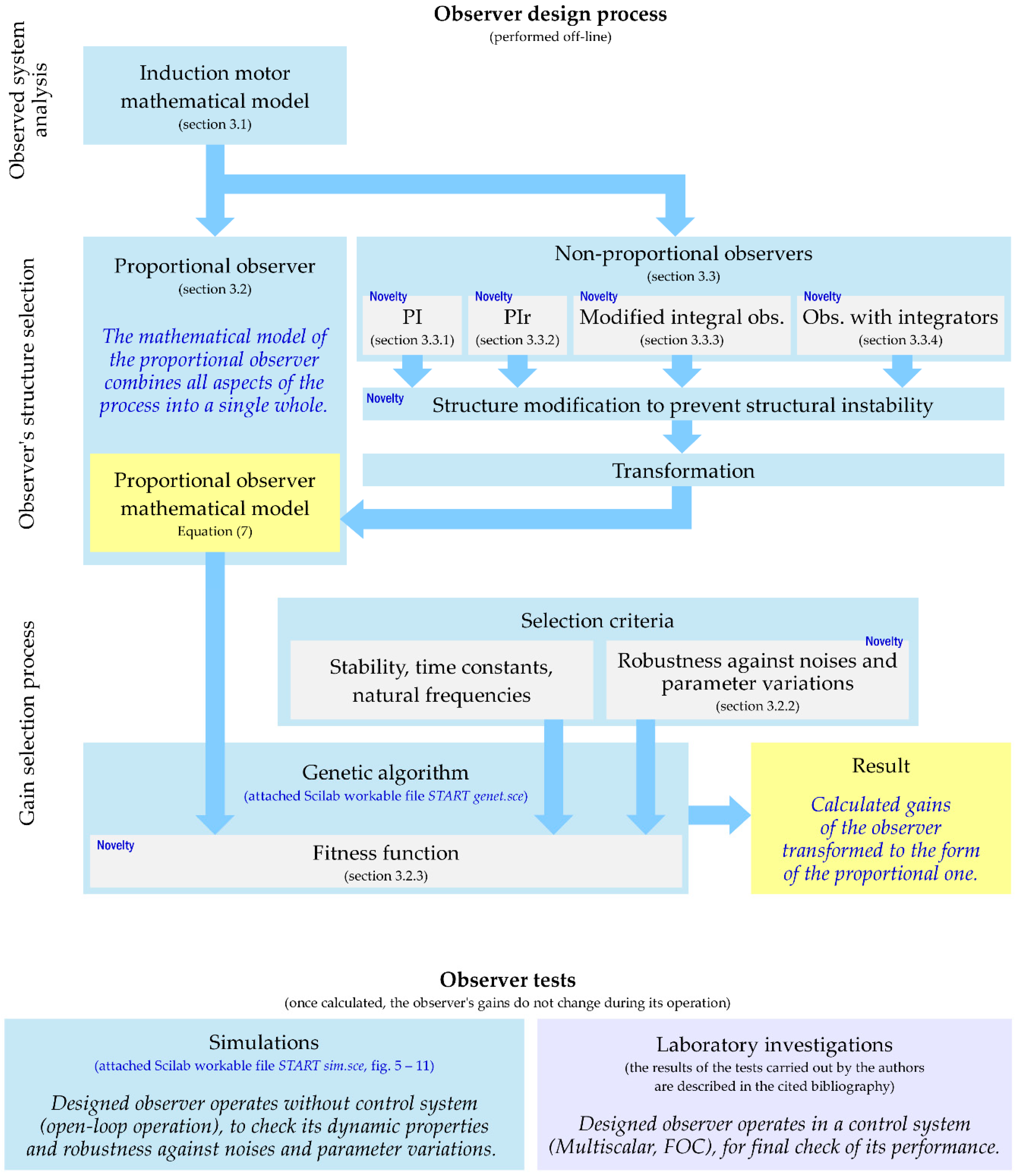
2. Methodology
3. Results
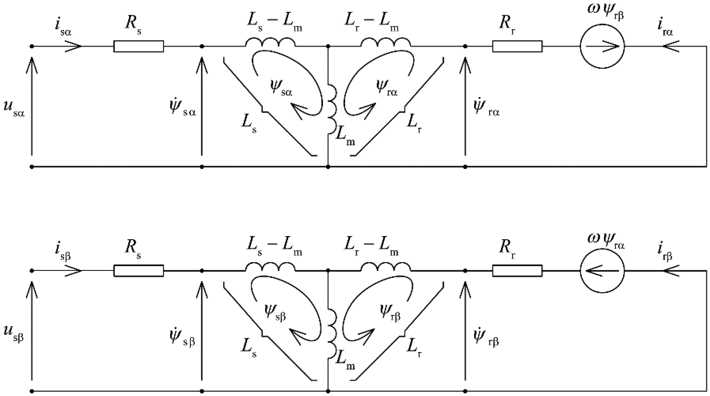
3.1. Mathematical Model of the Motor
3.2. Proportional Observer and Its Gain Selection
3.2.1. Error Equation and Disturbances
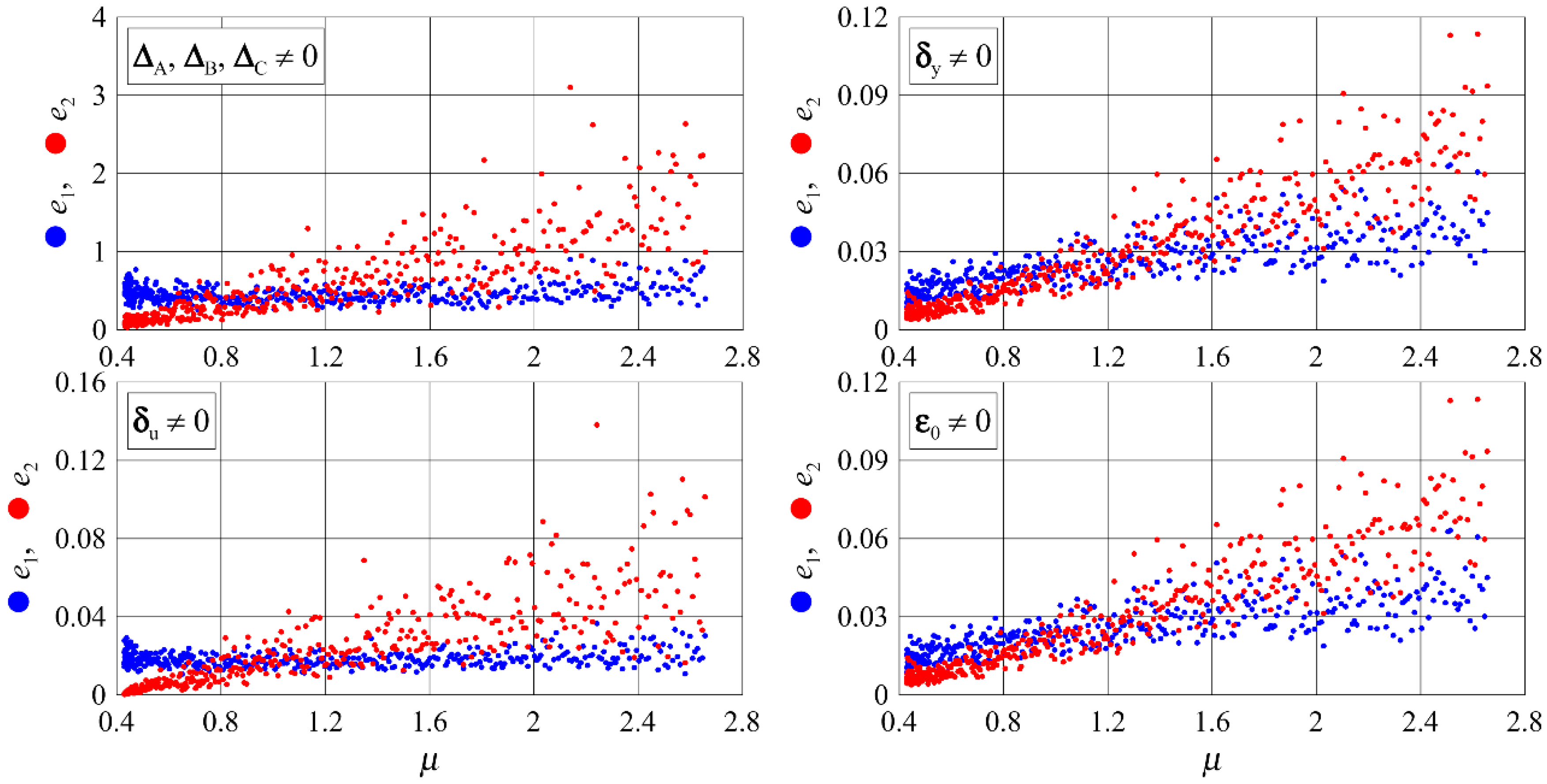
3.2.2. Amplification Index of the Observer
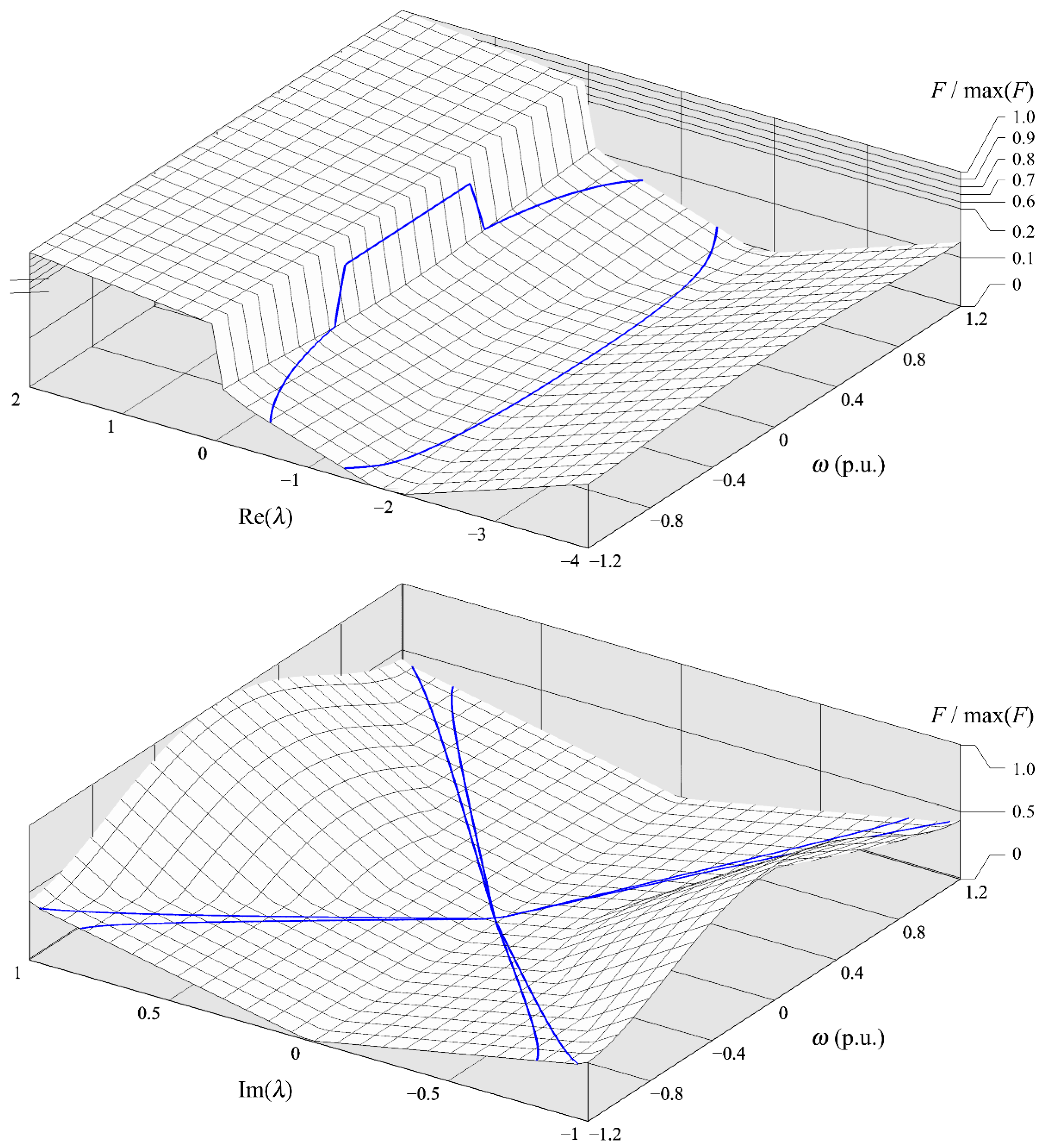
3.2.3. Optimization Gain Selection
3.3. Non-Proportional Observers
3.3.1. Proportional-Integral Observer
3.3.2. Reduced Order Integral Unit PI Observer
3.3.3. Modified Integral Observer
3.3.4. A Proportional Observer with Additional Integrators
4. Discussion
5. Conclusions
Supplementary Materials
Author Contributions
Funding
Conflicts of Interest
References
- Kubota, H.; Matsuse, K.; Nakano, T. DSP-based speed adaptive flux observer of induction motor. IEEE Trans. Ind. Appl. 1993, 27, 344–348. [Google Scholar] [CrossRef]
- Auger, F.; Hilairet, M.; Guerrero, J.M.; Monmasson, E.; Orlowska-Kowalska, T.; Katsura, S. Industrial applications of the Kalman filter: A review. IEEE Trans. Ind. Electron. 2013, 60, 5458–5471. [Google Scholar] [CrossRef]
- Urbański, K. Determining the observer parameters for back EMF estimation for selected types of electrical motors. Bull. Pol. Acad. Sci. Tech. Sci. 2017, 65, 439–447. [Google Scholar] [CrossRef][Green Version]
- Kazmierkowski, M.P.; Franquelo, L.G.; Rodriguez, J.; Perez, M.A.I.; Leon, J.I. High-Performance Motor Drives. IEEE Ind. Electron. Mag. 2011, 5, 6–26. [Google Scholar] [CrossRef]
- Kennel, R.; Rodriguez, J.; Espinoza, J.; Trincado, M. High Performance Speed Control Methods for Electrical Machines: An Assessment. In Proceedings of the IEEE International Conference on Industrial Technology, Vina del Mar, Chile, 14–17 March 2010; pp. 1793–1799. [Google Scholar]
- Rodriguez, J.; Kennel, R.M.; Espinoza, J.R.; Trincado, M.; Silva, C.A.; Rojas, C.A. High-Performance Control Strategies for Electrical Drives: An Experimental Assessment. IEEE Trans. Ind. Electron. 2012, 59, 812–820. [Google Scholar] [CrossRef]
- Wang, F.; Zhang, Z.; Mei, X.; Rodríguez, J.; Kennel, R. Advanced Control Strategies of Induction Machine: Field Oriented Control, Direct Torque Control and Model Predictive Control. Energies 2018, 11, 120. [Google Scholar] [CrossRef]
- Geyer, T.; Papafotiou, G.; Morari, M. Model Predictive Direct Torque Control—Part I: Concept, Algorithm, and Analysis. IEEE Trans. Ind. Electron. 2009, 56, 1894–1905. [Google Scholar] [CrossRef]
- Papafotiou, G.; Kley, J.; Papadopoulos, K.G.; Bohren, P.; Morari, M. Model Predictive Direct Torque Control—Part II: Implementation and Experimental Evaluation. IEEE Trans. Ind. Electron. 2009, 56, 1906–1915. [Google Scholar] [CrossRef]
- Wang, F.; Li, S.; Mei, X.; Xie, W.; Rodríguez, J.; Kennel, R.M. Model-Based Predictive Direct Control Strategies for Electrical Drives: An Experimental Evaluation of PTC and PCC Methods. IEEE Trans. Ind. Inf. 2015, 11, 671–681. [Google Scholar] [CrossRef]
- Karlovsky, P.; Lipcak, O.; Bauer, J. Iron Loss Minimization Strategy for Predictive Torque Control of Induction Motor. MDPI Electron. 2020, 9, 566. [Google Scholar] [CrossRef]
- Xinghua, Z.; Houbei, Z.; Zhenxing, S. Efficiency Optimization of Direct Torque Controlled Induction Motor Drives for Electric Vehicles. In Proceedings of the International Conference on Electrical Machines and Systems, Beijing, China, 20–23 August 2011; pp. 1–5. [Google Scholar]
- Khan, H.; Hussain, S.; Bazaz, M.A. Direct Torque Control of Induction Motor Drive with Flux Optimization. In Proceedings of the International Conference on Advances in Computing, Communications and Informatics (ICACCI), Kochi, India, 10–13 August 2015; pp. 618–623. [Google Scholar]
- Holtz, J. Sensorless Control of Induction Motor Drives. Proc. IEEE 2002, 90, 1359–1394. [Google Scholar] [CrossRef]
- Zaky, M.S.; Khater, M.; Yasin, H.; Shokralla, S.S. Review of different speed estimation schemes for sensorless induction motor drives. JEE 2008, 8, 102–140. [Google Scholar]
- Mousavi, S.M.; Dashti, G.A. Application of Speed Estimation Techniques for Induction Motor Drives in Electric Traction Industries and vehicles. Int. J. Automot. Eng. 2014, 4, 857–868. [Google Scholar]
- Wang, F.; Alireza Davari, S.; Chen, Z.; Zhang, Z.; Khaburi, D.A.; Rodríguez, J.; Kennel, R. Finite Control Set Model Predictive Torque Control of Induction Machine With a Robust, Adaptive Observer. IEEE Trans. Ind. Electron. 2017, 64, 2631–2641. [Google Scholar] [CrossRef]
- Ammar, A.; Kheldoun, A.; Metidji, B.; Ameid, T.; Azzoug, Y. Feedback linearization based sensorless direct torque control using stator flux MRAS-sliding mode observer for induction motor drive. ISA Trans. 2020, 98, 382–392. [Google Scholar] [CrossRef] [PubMed]
- Niestrój, R.; Białoń, T.; Pasko, M.; Michalak, J. Study of adaptive proportional observer of state variables of induction motor taking into consideration the generation mode. In Proceedings of the International Symposium on Electrical Machines (SME), Naleczow, Poland, 18–21 June 2017; pp. 1–6. [Google Scholar]
- Niestrój, R.; Białoń, T.; Pasko, M.; Lewicki, A. Selected dynamic properties of adaptive proportional observer of induction motor state variables. In Proceedings of the 13th Selected Issues of Electrical Engineering and Electronics (WZEE), Rzeszow, Poland, 4–8 May 2016; pp. 1–6. [Google Scholar]
- Zhang, Y.; Zhao, Z.; Lu, T.; Yuan, L.; Xu, W.; Zhu, J. A Comparative Study of Luenberger Observer, Sliding Mode Observer and Extended Kalman Filter for Sensorless Vector Control of Induction Motor Drives. In Proceedings of the IEEE Energy Conversion Congress and Exposition, San Jose, CA, USA, 20–24 September 2009; pp. 2466–2473. [Google Scholar]
- Cuibus, M.; Bostan, V.; Ambrosii, S.; Ilas, C.; Magureanu, R. Luenberger, Kalman and Neural Network Observers for Sensorless Induction Motor Control. In Proceedings of the IPEMC 2000. Third International Power Electronics and Motion Control Conference (IEEE Cat. No. 00EX435), Beijing, China, 15–18 August 2000. [Google Scholar]
- Harnefors, L. A comparison between directly parametrised observers and extended Kalman filters for sensorless induction motor drives. In Proceedings of the International Conference on Power Electronics and Variable Speed Drives, London, UK, 21–23 September 1998. [Google Scholar]
- Manes, C.; Parasiliti, F.; Tursini, M. A Comparative Study of Rotor Flux Estimation in Induction Motors with a Nonlinear Observer and the Extended Kalman Filter. In Proceedings of the IECON’94-20th Annual Conference of IEEE Industrial Electronics, Bologna, Italy, 5–9 September 1994; pp. 2149–2154. [Google Scholar]
- Pimkumwong, N.; Wang, M.S. Full-order observer for direct torque control of induction motor based on constant V/F control technique. ISA Trans. 2018, 73, 189–200. [Google Scholar] [CrossRef]
- Kadrine, A.; Tir, Z.; Malik, O.P.; Hamida, M.A.; Reatti, A.; Houari, A. Adaptive non-linear high gain observer based sensorless speed estimation of an induction motor. J. Franklin Inst. 2020, 357, 8995–9024. [Google Scholar] [CrossRef]
- Gao, Z.; Habetler, T.G.; Harley, R.G.; Colby, R.S. A Sensorless Adaptive Stator Winding Temperature Estimator for Mains-Fed Induction Machines with Continuous-Operation Periodic Duty Cycles. IEEE Trans. Ind. Appl. 2008, 5, 1533–1542. [Google Scholar]
- Espinoza-Trejo, D.R.; Campos-Delgado, D.U.; Martinez-Lopez, F.J. Variable Speed Evaluation of a Model-Based Fault Diagnosis Scheme for Induction Motor Drives. In Proceedings of the IEEE International Symposium on Industrial Electronics, Bari, Italy, 4–7 July 2010; pp. 2632–2637. [Google Scholar]
- Kim, H.S.; Lee, C.H.; Ahn, H.U.; Kim, S.B. Sensorless Speed Control of Induction motor Using observation Technique. J. Korean Soc. Mar. Eng. 1999, 1, 96–102. [Google Scholar]
- Gaddouna, B.; Ouladsine, M.; Rachid, A.; El Hajjaji, A. State Estimation of an Induction Machine using a Reduced Order PI Observer. In Proceedings of the Multiconference on Computational Engineering in Systems Applications IEEE Conf, CESA, Nabul-Hammamat, Tunisia, 1–4 April 1998; pp. 1022–1026. [Google Scholar]
- Białoń, T.; Lewicki, A.; Niestrój, R.; Pasko, M. Stability of a proportional observer with additional integrators on the example of the flux observer of induction motor. Electron. Rev. 2011, 87, 142–145. [Google Scholar]
- Hu, J.; Wu, B. New Integration Algorithms for Estimating Motor Flux over a Wide Speed Range. IEEE Trans. Power Electron. 1998, 5, 969–977. [Google Scholar]
- Toumi, D.; Segueir Boucherit, M.; Tadjine, M. Observer-based fault diagnosis and field oriented fault tolerant control of induction motor with stator inter-turn fault. Arch. Electron. Eng. 2012, 61, 165–188. [Google Scholar] [CrossRef]
- Krzemiński, Z.; Lewicki, A.; Morawiec, M. Speed observer based on extended model of induction machine. In Proceedings of the IEEE International Symposium on Industrial Electronics, Bari, Italy, 4–7 July 2010; pp. 3017–3112. [Google Scholar]
- Białoń, T.; Lewicki, A.; Pasko, M.; Niestrój, R. Non-proportional full-order Luenberger observers of induction motors. Arch. Electron. Eng. 2018, 67, 925–937. [Google Scholar]
- IEEE Standard Definitions of Basic Per Unit Quantities for Alternating-Current Rotating Machines; IEEE Std 86-1975; The Institute of Electrical and Electronics Engineers, Inc.: New York, NY, USA, 1975; pp. 1–10.
- Amrane, A.; Larabi, A.; Aitouche, A. Unknown input observer design for fault sensor estimation applied to induction machine. Math. Comput. Simul. 2020, 167, 415–428. [Google Scholar] [CrossRef]
- Ellis, G. Observers in Control Systems; Academic Press: Cambridge, MA, USA, 2002. [Google Scholar]
- Korbicz, J. Robust fault detection using analytical and soft computing methods. Bull. Pol. Acad. Sci. Tech. Sci. 2006, 54, 75–88. [Google Scholar]
- Niestrój, R. Analysis of selected dynamic properties of adaptive proportional observer of induction motor state variables. Q. Elektr. 2015, 61, 7–28. (In Polish) [Google Scholar]
- Francisco, M.; Revollar, S.; Vega, P.; Lamanna, R. A comparative study of deterministic and stochastic optimization methods for integrated design of processes. IFAC Proc. 2005, 38, 335–340. [Google Scholar] [CrossRef]
- Busawon, K.K.; Kabore, P. Disturbance attenuation using proportional integral observers. Int. J. Control 2001, 74, 618–627. [Google Scholar]
- Nazari, S.; Shafai, B. Distributed Proportional-Integral Observers for Fault Detection and Isolation. In Proceedings of the IEEE Conference on Decision and Control (CDC), Miami Beach, FL, USA, 17–19 December 2018; pp. 6328–6333. [Google Scholar]
- Białoń, T.; Lewicki, A.; Pasko, M.; Niestrój, R. Parameter selection of an adaptive PI state observer for an induction motor. Bull. Pol. Acad. Sci. Tech. Sci. 2013, 61, 599–603. [Google Scholar]
- Wang, X.T.; Yu, H.H. Generalized PI observer design for descriptor linear system. Arch. Control Sci. 2019, 29, 585–601. [Google Scholar]
- Hussein, A.A. Implementation of Proportional-Integral-Observer Techniques for Load Frequency Control of Power System. In Proceedings of the 8th International Conference on Ambient Systems, Networks and Technologies, ANT-2017 and the 7th International Conference on Sustainable Energy Information Technology, SEIT 2017, Madeira, Portugal, 16–19 May 2017; pp. 754–762. [Google Scholar]
- Hu, F.R.; Hu, J.S. Pole placement design of proportional-integral observer with stochastic perturbations. Eng. Comput. 2016, 33, 1729–1741. [Google Scholar] [CrossRef]
- Jiang, G.P.; Wang, S.P.; Song, W.Z. Design of observer with integrators for linear systems with unknown input disturbances. Electron. Lett. 2000, 36, 1168–1169. [Google Scholar] [CrossRef]


| The Number of the Term Fi |
Weight Coefficient wi | Coefficients cm of the λref Polynomial m (24) | ||
|---|---|---|---|---|
| m = 0 | m = 2 | m = 4 | ||
| 1 | 20 | - | - | - |
| 2 | 1 | - | - | - |
| 3 | 1 | −2 | - | - |
| 4 | 1 | −0.96 | −0.96 | 0.32 |
| 5 | 1 | −0.195 | −0.065 | −0.0325 |
| 6 | 0.1 | −2.6 | 0.65 | −0.325 |
| 7 | 0.05 | - | - | - |
| 8 | 0.1 | 0.3 | 0.9 | −0.3 |
Publisher’s Note: MDPI stays neutral with regard to jurisdictional claims in published maps and institutional affiliations. |
© 2020 by the authors. Licensee MDPI, Basel, Switzerland. This article is an open access article distributed under the terms and conditions of the Creative Commons Attribution (CC BY) license (http://creativecommons.org/licenses/by/4.0/).
Share and Cite
Białoń, T.; Pasko, M.; Niestrój, R. Developing Induction Motor State Observers with Increased Robustness. Energies 2020, 13, 5487. https://doi.org/10.3390/en13205487
Białoń T, Pasko M, Niestrój R. Developing Induction Motor State Observers with Increased Robustness. Energies. 2020; 13(20):5487. https://doi.org/10.3390/en13205487
Chicago/Turabian StyleBiałoń, Tadeusz, Marian Pasko, and Roman Niestrój. 2020. "Developing Induction Motor State Observers with Increased Robustness" Energies 13, no. 20: 5487. https://doi.org/10.3390/en13205487
APA StyleBiałoń, T., Pasko, M., & Niestrój, R. (2020). Developing Induction Motor State Observers with Increased Robustness. Energies, 13(20), 5487. https://doi.org/10.3390/en13205487