1. Introduction
In order to facilitate long-term sustainable energy generation, significant changes within the energy system have to be accomplished to enable infrastructures that are mainly or even entirely based on renewable energy sources (RES). Solutions to successfully achieve the transition to a sustainable energy future aim at efficiently integrating renewable energies into the grid or using available energy within the overall energy system more efficiently. For many of these solutions, more research is needed, especially regarding infrastructural impacts as well as grid bottlenecks, in order to enable an efficient implementation [
1,
2,
3].
One of these solutions is the multi-energy system (MES), which enables the use of energy across energy carriers, thus facilitating a more efficient use as well as a better integration of renewable energy sources. These systems require major changes in the structure and operation of current energy networks which transport and distribute grid-bound energy individually to customers. Thus, present-day electrical networks are operated as independent network structures without utilizing possible connections and synergies to other energy carrier networks. Since the integration of RES into current structures burdens mainly electrical networks, intersectoral load shifts into other energy carrier networks could reduce or even avoid excessive strains. Energy exchange between different energy carrier networks, therefore, may stabilize electrical networks as well as the entire energy system. This enables a more flexible reaction to volatile, decentralized and unpredictable generation of RES. Thus, it is easier to preserve the balance between energy generation and energy consumption at all times within the grid. Significant advantages regarding primary energy use due to utilizing cascaded energy chains and exergetic potentials can, additionally, be achieved. However, in order to ensure the above mentioned benefits of multi-energy systems, efficient planning within the entire energy system is required. Therefore, a hybrid load flow modelling framework, HyFlow [
4], was developed at the Chair of Energy Network Technology at the Montanuniversitaet Leoben, which aims at evaluating the influence of hybrid networks within the Austrian energy system and their potential contribution for decarbonizing the energy sector [
4].
For developing and improving innovative tools, such as HyFlow, appropriate test networks including an extensive data basis of all network components are of great importance. These test networks aim at reproducing the behavior of a real network [
5] and can either be used to investigate the effects of different new technologies on the network structures (impact studies on grids) or to test algorithms and program structures. Additionally, test networks also allow one to consistently compare different algorithms. Since transmission and distribution network data of a country is usually not publicly available to be used as test cases due to data protection regulations, only a few real networks are available for research purposes. Therefore, generic test networks have been continuously created and published in literature to provide test cases to the research community. For developing test networks, there are four different approaches [
6]:
Feeder anonymization: removing private and/or sensitive data from real networks resulting in real test networks.
Cluster and Combine: using clustering techniques to group together a number of real networks and then assemble the pieces to a synthetic test network.
Manual design: focusses on specific network features resulting in a very complex process for creating the synthetic test network.
Planning tools: tools that are designed to create realistic networks by considering technical and economic criteria.
The most important criterion for obtaining conclusive results from test networks, e.g., regarding RES integration, is representativeness which refers to the ability of a test network to reproduce the characteristics of a real network [
6]. Usually it is not explicitly clear for every available test network in the literature whether this feature is fully achieved. Additionally, only very few European test networks are available in the literature and even fewer offer appropriate data for the included network elements. The presented networks, therefore, provide a basis for European test networks within the ENTSO-E (European Network of Transmission System Operators for Electricity) interconnected system for the integration of renewable energy sources and can be extended or adapted for other or more detailed applications. This paper, thus, offers a contribution to the research community regarding European structures by addressing the following research questions:
Which qualities do the test networks available in the literature offer (in general and specifically for European structures)?
What are the gaps in these test networks, especially regarding RES integration, and how can comprehensive test networks be obtained without these gaps?
The first research question refers to identifying the qualities (available voltage levels, number of feeders, available load and generation data, grid representation, network size, adaption to other application purposes) regarding the representation of the overall energy system, especially for integrating RES in European grids. The second research question, then, assesses which of the available test networks in the literature have gaps regarding the necessary qualities for RES integration, which will reveal the need for further test networks. Subsequently, this paper develops test networks which fill these gaps. Thus, the paper is divided in the following sections.
In
Section 1.1, currently available test networks or test feeders are comprehensively reviewed to provide an overview.
Section 1.2 then addresses these research questions and shows the limitations of the available networks, which will lead to the conclusion why specific test networks for the integration of RES in European infrastructures are required. This section is followed by
Section 2, which presents the development of the generic test networks for each voltage level common in the European ENTSO-E interconnected system and addresses the used methodology of manual design.
Section 3 then shows the results obtained from performing a short-circuit analysis, where the maximum short-circuit power and the maximum short-circuit current are determined for each test network to validate their representativeness. In
Section 4, these results are discussed in detail. Additionally,
Section 4 reviews the test network limitations from the literature addressed in
Section 1.2 to show the improvements achieved for the developed test networks and their remaining limitations.
Section 5 then summarizes the presented work and provides an outlook.
1.1. State of Research in Test Networks
In the following, current publicly available test feeders, which are usually comprised of only one feeder, as well as test networks, which are comprised of several feeders and therefore more closely replicate real grids, and their design approaches are presented. This section shows the characteristics of different test networks and enables the need for test networks to be derived, specifically representing European structures for networks within the ENTSO-E interconnected grid, such as Austrian grids, in detail.
1.1.1. IEEE (Institute of Electrical and Electronics Engineers) Test Feeders
The first set of test feeders was published in 1991 [
7]. These first four test feeders are models of real radial distribution networks in the United States [
5]. Over the years, more test feeders were added to include different features within the networks [
5]. All of the added networks are also representative for the US; only in recent years have low-voltage networks and one network based on European electrical energy system structures been published [
5]. A total of 11 test feeders can be found on the IEEE PES (IEEE Power and Energy Society) website [
8] and are summarized in
Table 1. The table shows total line lengths, voltage levels as well as application purposes for each test feeder.
The IEEE 13 node test feeder presents a highly loaded 4.16 kV network including one substation regulator as well as overhead and underground lines, shunt capacitor banks, in-line transformers and unbalanced spot or distributed loads [
7].
The IEEE 123 node test feeder operates at a nominal primary voltage of 4.16 kV, which is not common, but provides voltage drop problems. Therefore, the application of voltage regulators and shunt capacitors can be tested. Additionally, due to spot loads and a multitude of switches within the test feeder, optimal configuration procedures as well as load allocations can be studied [
7].
The IEEE 34 node test feeder represents a real feeder in Arizona with long and highly loaded lines and three in-line regulators, of which two are used to maintain a smooth voltage profile, and the third is used to reduce the voltage to 4.16 kV for a short section of the feeder [
7].
Similarly, the IEEE 37 node test feeder represents a real feeder located in California with a nominal voltage of 4.8 kV. Electrical lines all represent underground lines and spot loads with highly unbalanced loadings occur in this test feeder [
7].
For testing all possible three-phase transformer connections with the possibility for step-up (secondary voltage of 24.9 kV) as well as step-down (secondary voltage of 4.16 kV) operations, the IEEE four node test feeder can be used. The load can either be balanced or unbalanced [
7].
The purpose of the neutral-to-earth voltage test case (NEV) is solving the neutral-to-earth voltage problem [
8], also called stray voltage, which is a result of electrical current flowing through a neutral conductor. In addition to other test feeders, which are capable of modelling NEV problems, this test feeder is for distribution system analysis including all aspects of steady-state frequency-domain analysis in distribution networks [
8]. Therefore, this test feeder can be used for load modeling studies [
6,
10,
11,
12]. Since NEV problems basically represent third order harmonics as well as fundamental frequency voltage, which requires a solution of the system at two different frequencies [
8,
20], the test network can also be used for harmonic analysis [
6,
13].
The IEEE 8500 node test feeder is based principally on a real network in the USA and contains common features of North American networks such as a high number of voltage regulators (load tap changer at the substation and multiple feeder regulators and switched capacitor banks), per-phase capacitor control, low-voltage secondaries, as well as centered-tapped transformers. This network enables testing of the application of algorithms, e.g., for distribution system analysis on large systems. Therefore, it is used primarily for power flow solutions but also for distribution automations (voltage and var control simulations) as well as annual load shape simulations for evaluating energy efficiency options, renewable energy generation and electric vehicle impacts [
14].
The CTF (comprehensive distribution test feeder) includes most of the available configurations as well as electrical equipment and, therefore, represents a detailed network [
15]. The components within the feeder include overhead lines, underground cables, transformer connections, center tapped transformers, step voltage regulators, switches, induction machines, distributed and spot loads as well as switched capacitor banks and center tapped loads and transformer substations [
15]. Therefore, the model can be used to test the models of all distribution components as well as their convergence qualities [
15]. Due to the included switching devices a wide range of network configuration possibilities can be created [
6]. Outside of software testing issues, the results obtained from this network can be unrealistic [
6].
The IEEE 342 node low-voltage network test feeder represents a moderately sized, unbalanced and highly meshed urban system. This 120/208 V network is fed by primary feeders from the 13.2 kV-voltage level. Additionally, to facilitating the assessment of non-radial, highly meshed systems, it is also possible to test systems with numerous parallel transformers and parallel low-voltage lines [
17].
Since the above presented IEEE test feeders are based on North American network infrastructures, which differ from European grids regarding the distribution system configuration, the EuropeanLV (Low-Voltage) test feeder focuses on European grid infrastructures [
8]. Additionally, this circuit introduces quasi-static time series power flow solutions, which are provided for this feeder using the electric power distribution system simulator OpenDSS (EPRI (Electric Power Research Institute), Palo Alto, CA, USA) [
21] and the power distribution analysis tool GridLAB-D (U.S. Department of Energy (DOE) at Pacific Northwest National Laboratory (PNNL), Washington, DC, USA) [
22]. On the IEEE PES Resources online site [
8], the load profiles used in the feeder with a one-minute time resolution over 24 h are provided as well [
8]. This feeder can be used for distributed energy resources (DER) studies in low-voltage networks with European distribution system configurations [
23].
1.1.2. PNNL (Pacific Northwest National Laboratory) Taxonomy Feeders
A big barrier for smart grid technology integration into present-day grids is the lack of adequate assessment possibilities of their impact on electrical infrastructures [
24]. Besides others, this refers to the lack of distribution test feeders for such purposes. Therefore, the PNNL (Pacific Northwest National Laboratory) collected 575 distribution feeder models in the US and analyzed regional differences in feeder design and operation. Since nominal voltage level, climate region, and load composition are not sufficient characteristics for the feeders in the US, graph theory was used to identify designs that additionally characterize the feeders, such as overhead circuit length, feeder ratings and connected apparent power profile type (residential, commercial, industrial, agricultural). In total, 35 statistical and electrical properties were studied. Based on this analysis and the utilization of hierarchical clustering algorithms, a taxonomy of 24 prototypical feeder models was created that is representative of a class of distribution feeders found in each of the climate regions in the US. These feeders were then modelled in GridLAB-D and, since utility specific information was removed from the feeders, unrestrictedly distributed [
24]. Further, more detailed information about the creation and description of the PNNL taxonomy feeders can be found in the report [
24], and a short summary of the test feeders can be found in
Table 2.
The loads within these test feeders are either residential (single- or multi-family households), commercial (light, moderate or heavy), industrial (light, moderate or heavy) or agricultural (light, moderate or heavy). The feeders consist of a maximum of 2000 network nodes and a minimum of 52 network nodes. The general feeder (GC-12.47-1) can exist in any of the five climate regions. Therefore, the feeder consists of only 27 network nodes [
24].
The application purpose of the PNNL-taxonomy feeders is the analysis of new technologies for distribution systems, especially, for DER studies [
25,
26] and reliability analysis [
26,
27,
28], since they assume that the solution method for power flow calculations is valid [
6,
29].
1.1.3. EPRI (Electric Power Research Institute) Representative Feeders
The test feeders published by the EPRI (Electric Power Research Institute) are obtained from real networks and, therefore, include bus relative coordinates as well as time-series data in order to offer more realistic test cases for the US-continental area [
6]. The first three feeders (feeder J1 [
30], feeder K1 [
31] and feeder M1 [
32]) are focused on distributed photovoltaic (PV) monitoring and feeder analysis in order to assess the impact of different levels of distributed photovoltaic penetration [
6]. The application purposes of the last three feeders (feeder Ckt5, feeder Ckt7 and feeder Ckt24) are investigations of smart grid issues [
33].
Table 3 shows a short summary of the EPRI test feeders:
Feeder J1 is located in the northeastern US and supplies the nearest town as well as surrounding rural areas and farms [
30]. Since voltage violations are caused by very fast ramp rates of the PV, voltage regulators are not capable of operating quickly enough to compensate or mitigate these effects [
30]. Therefore, this feeder aims at finding solutions for areas exceeding the voltage limits [
6].
Feeder K1 is located in the southeastern US and supplies commercial units and residential customers [
31]. Within this feeder there are no dedicated voltage regulators; voltage regulation is provided by a load tap changer (LTC) at the substation [
31]. Consequently, this feeder enables grid calculations for analyzing grids with high PV penetrations and without voltage regulators [
6].
Feeder M1 contains a substation transformer to a secondary lower voltage level, which is modelled in detail including the installed radio controlled capacitor banks for reactive power compensation [
32]. These capacitor banks manage to maintain a set power factor at the low-voltage level [
32]. The intention of this feeder is to study capacitor bank management strategies for setting a suitable power factor [
6].
Feeder Ckt5, Ckt7 and Ckt24 are test feeders for power flows in smart grids and mainly aim to study Volt/VAr control strategies in grids with high PV penetration to compensate overvoltage problems [
6,
33,
34,
35,
36]
1.1.4. PG&E (Pacific Gas and Electric Company) Prototypical Feeder Models
The PG&E (Pacific Gas and Electric Company), the largest energy supplier in the US, provides 12 prototypical feeder models, which are obtained from a k-means cluster analysis of 2700 primary distribution feeders of PG&E’s supply area [
37]. The k-means cluster analysis forms a previously known number of k group from a large set of similar objects [
6]. The resulting 12 feeder models are statistically representative of the entire supply area of PG&E [
37]. The PG&E prototypical feeders represent different network structures, various sizes (ranging from approximately 100 to 200 network nodes) as well as a mix of different consumers [
6]. The feeder models are available in GridLAB-D [
37]. The application purpose of these feeders are studies regarding the impact of DER within different scenarios [
6]. The six feeder models with primary medium-voltage are described more in detail in [
38], and their characteristics can be found in
Table 4 [
38]. Additionally, the PG&E prototypical feeder models provide detailed low-voltage secondary networks, which connect the customers to the transformer terminals at the substations, making these test feeders distinctive from other test feeders [
38].
1.1.5. Benchmark Models
A benchmark model is an electrical network model that maintains the important technical characteristics of real grids, but is less complex than the actual network, in order to permit efficient modelling and simulation of network operation [
39].
North-American Low-Voltage Distribution Benchmark Network
This North-American low-voltage distribution benchmark test feeder was developed by the CIGRÉ (Conseil International des Grands Réseaux Électriques) Task Force C6.04.02, originally, for the evaluation of methods and techniques for efficient network integration of DER [
40]. Therefore, this test feeder aims at reproducing the characteristics and behavior of real low-voltage networks [
6]. The topology of this feeder is comprised of three subnetworks, each subnetwork designed to supply different load types (residential, light industrial and light commercial) [
40]. The primary voltage of this feeder is 12.47 kV (60 Hz), and the total line length is 0.59 km [
40]. The application purpose is network management analysis, such as power management, to effectively decouple real and reactive power flows to increase system stability [
41,
42] or transient time-domain simulation studies for protection strategies [
43].
European Low-Voltage Distribution Benchmark Network
Due to the increasing penetration of DER in the low-voltage grid (PV-units, CHP (combined heat and power)-micro turbines, small wind turbines and possibly fuel cells), future grid operation has to change compared to present-day networks. Since microgrids present possible options to operate efficiently for such conditions, this feeder model represents a low-voltage microgrid test network for European grids. For the creation of this test feeder, it was important to preserve the technical characteristics of real networks while simplifying the complexity of real networks. This allows for efficient modelling and simulation of operation within microgrids while simultaneously providing conclusive results. Therefore, the focus was primarily on infrastructural and technical network parameters, not on connected network elements or applied control concepts. In order to obtain a benchmark model, a simple low-voltage microgrid test network is used and expanded. This low-voltage test network has a primary voltage of 0.4 kV supplied from the 20 kV-medium-voltage level. It represents a suburban area with single- and multi-residential consumers as well as apartment buildings. The total line length corresponds with 0.54 km and as line types, underground cables as well as overhead lines are used. For all consumers a power factor of 0.85 is assumed, and aggregated daily load curves are provided for this test network by Papathanassiou et al. (2005) [
39]. The benchmark model is expanded by two circuit breakers for possible sectionalizing, a flywheel storage/batteries, a microturbine, a wind turbine, two PV-units as well as a fuel cell. These elements can be specified with suitable models individually for application studies. Therefore, this test network model is suitable for steady state and transient simulations for microgrids [
39].
This low-voltage test network was first developed within the EU project “Microgrids” [
44] and later adopted by the CIGRÉ Task Force C6.04.02 [
39]. The CIGRÉ Task Force also provides an extended multi-feeder version with three individual low-voltage microgrids [
39,
45]. The first subnetwork is the 0.4 kV line-to-line residential test feeder described above [
39,
45]. The second subnetwork is a 0.4 kV line-to-line industrial test feeder with only one consumer and a total line length of 0.20 km [
45]. The third subnetwork is a 0.4 kV line-to-line commercial test feeder with 15 consumers and a total line length of 0.57 km [
45]. This extended multi-feeder version is used for dynamic simulations such as frequency response analysis [
46].
European Medium-Voltage Distribution Benchmark Network
CIGRÉ Task Force C6.04.02 developed this medium-voltage test network in order to study various aspects of integrating DER into the medium-voltage network. This test feeder model is capable of retaining the characteristics of a real network since it is based on a German medium-voltage distribution grid within a rural area supplying a small town as well as the surrounding rural area. The nominal voltage of the network is 20 kV supplied by a transformer substation from the 110 kV-high-voltage level. For the test network model, the German reference model is separated into two subnetworks connected over the common substation. In this configuration, the distribution benchmark test network represents a radial network structure. Additionally, there is the possibility to couple the two feeders within the model using a medium-voltage direct current coupler (MVDC). This optional configuration enables also a closed ring network structure. The total line length of the benchmark test network is 15 km comprised mostly of cables, with some overhead line sections. In order to facilitate an adaption of the benchmark model to regionally varying parameters, the original values of the German reference grid were transferred into the per unit system. The loads within the test network are either industrial or residential consumers. There are various application purposes regarding distributed generation (DG) integration for this benchmark test network that include studying the impact of DG units on power flows, voltage profiles and transmission capability, as well as investigating distributed energy management systems (DEMS), small signal stability, system protection and power quality issues (harmonics, flicker, frequency and voltage variations). Additionally, the impact of MVDC coupling on power flows and voltage profiles can be assessed [
47].
Additionally, to this basic medium-voltage distribution benchmark network, there are two extended versions of this benchmark network. First, there is a medium-voltage distribution network with PV and wind DER, including nine supplementary distributed energy resources (PV and wind generation units) [
45]. Second, there is a medium-voltage distribution network with all DER [
45]. This network includes an additional 15 DER, including PV units, wind turbines, batteries, residential fuel cells, CHP diesel units and CHP fuel cells [
45].
European High-Voltage Transmission Benchmark Network
The CIGRÉ Task Force C6.04.02 also published a high-voltage level transmission benchmark network model, which consists of two different voltage levels, namely the 380 kV-voltage level and the 220 kV-voltage level. The network topology represents a closed ring structure. The total line length within this benchmark network is 2100 km, where 600 km of electrical line length belong to the 380 kV-voltage level and 1500 km belong to the 220 kV-voltage level. There are no consumer units at the 380 kV-voltage level, only at the 220 kV-level. Two transformers connect the two voltage levels. Just like the other above presented CIGRÉ test networks this benchmark model facilitates the analysis and validation of new methods and techniques aiming at enabling the economic, robust and environmentally responsible integration of DER into the European grids [
45].
1.1.6. Agent-Based Distribution Test Feeders
Agent-based test feeders refer to the characteristic that the distribution feeder components are modeled as interacting agents, acting based on individually specified objectives or purposes due to financial and/or physical constraints [
48]. Agent-based modelling usually addresses different application purposes, where a system is investigated on its ability to adapt to changing boundary conditions. However, with grid modelling for smart grid applications, this modelling approach may be supported by this technique for analyzing impacts of smart grid technologies on distribution feeders as well as performance evaluations of smart-grid market design.
The agent-based distribution test feeder presented by Jahangiri et al. (2012) [
48] is based on a real feeder in Iowa and includes detailed information about feeder equipment (fuses, switches, overhead and underground lines, as well as transformers) and residential and commercial customers. The customers are virtually equipped with various smart-grid enabled technologies (rooftop PV-units, price-responsive demands such as plug-in electric vehicles (PEV) and intelligently controlled air conditioning). For the PV generation, effects of cloud-passing are also considered as well as realistic travel pattern data for PEV load models. The application purpose of this test feeder, therefore, is the evaluation of the impacts of smart-grid market designs as well as the development of smart-grid features (demand response, dynamic-price retail contracting, distributed generation and energy storage systems) on distribution feeders. The primary voltage of the feeder is 13.2 kV. The exact geographic coordinates of the components as well as electrical data for the test feeder model are available in GridLAB-D, offering the possibility to simulate a time period with user-defined time steps [
48].
This test feeder is mainly used in smart-grid studies, such as in [
49], where future requirements for supporting flexible, intelligent and active power grid management is studied, and planning process analysis, such as in [
50,
51], where innovative distribution grid operation concepts including RES, demand side management (DSM) and storages are investigated [
6].
1.1.7. Test Feeder for DG Protection Analysis
This test feeder model allows for the comparison of different DG protection analysis tools, which have to be able to calculate fault currents, voltage and other values for different fault types and resistance values [
52]. This test feeder is based on an actual feeder with a 1.65 MW wind turbine [
52]. Therefore, the model consists of two different generation sources—the substation from the higher voltage level and the distributed generation source [
52]. The model operates at a 12.47 kV-voltage level with a substation source of 34.5 kV of nominal voltage [
52]. The total line length of the test feeder is 47.52 km [
52]. This feeder is used, for example, in symmetrical component calculations for single line-to-ground fault (SLGF) currents and the related over voltages for a distribution circuit with solar photovoltaic inverter-based generation [
53].
1.1.8. European Representative Synthetic Distribution Test Networks
For these test networks, two categories can be defined: first, large-scale networks modelling the network from a high-voltage/medium-voltage substation to the low-voltage level including all electrical components (consumers, feeders, substation) at the medium- and low-voltage level; second, feeder type networks, which feature common topologies of medium-and low-voltage levels. There are three large-scale and six feeder type test networks openly available in MATLAB
®/MATPOWER format, and they are all three-phased and balanced. The data for these test networks were collected over online questionnaires and distributed to the participating 79 European DSOs (distribution system operators), which were published in a report [
54]. This database covers 74.8% of the connected customers in the European Union. Based on this data, 36 indicators were developed, providing information about structural differences as well as similarities among distribution grids throughout Europe. This analysis provides three categories, each of which includes a set of indicators, namely network structure, network design and characteristics of distributed generation. The indicators for network structure include parameters such as number of customers, amount of distributed energy, areas of supply as well as circuit length and capacities of substations. The network design indicators include typical parameters of substations and feeders used for sizing and designing distribution installations. The category of distributed generation characteristics includes installed capacities per consumer as well as percentage of distributed generation connected at each voltage level [
54,
55].
The voltage levels occurring in these test networks range from the high-voltage level (HV: 132 kV) over the medium-voltage level (MV: 1–36 kV) to the low-voltage level (LV: <1 kV).
Table 5 provides an overview of the available networks, both large-scale as well as feeder types [
54,
55].
The application of these networks aims at supporting research on future distribution grids, and, therefore, they have already been used in several studies [
55]. The large-scale distribution networks are used in optimal power flow studies [
56] as well as data-driven approaches to reconstruct medium- and low-voltage grid topologies from smart meter data [
57]. The feeder type networks have been used to investigate the impact of electric vehicle recharging strategies in combination with high PV-penetration on the grid [
58]. These test networks have also been used for single-phase real-time simulations testing the impact of distributed generation [
59] as well as performance studies of power line communications [
60] and quantitative assessing impacts of different PV sizing and deployment rates on grid congestion and voltage unbalance [
61].
1.1.9. European Non-Synthetic Low-Voltage Test Network
This test network represents a non-synthetic comprehensive low-voltage distribution test network, which represents the grid of a real European town. The data of this network is extracted directly from the GIS system. The primary phase-to-phase voltage is 0.416 kV with a frequency of 50 Hz. There are 30 substations and 10,290 network nodes, resulting in a total line length of the grid lines of 45.94 km. For the loads, time series data with an hourly resolution over a 20-day period are available with the test network. The application purposes of this test feeder are developing and testing different kinds of software as well as distribution system optimization studies and state estimation techniques. The datasets for this test network are publicly available [
62,
63].
There are further test networks available, which address specific networks, e.g., for North England grids, which represent synthetic low-voltage residential feeders obtained from different clustering algorithms [
64] or for Western Australian medium- and low-voltage distribution feeders using a taxonomy approach that combines cluster analysis with discriminant analysis [
65].
1.2. Limitations of the Presented Test Networks
This section summarizes the findings about the presented test networks and test feeders and draws conclusions from the available datasets in order to show the limitations of these networks.
From the literature review presented above, it can be concluded that much work has been done for North American test feeders, but, in comparison, few studies are available for European networks.
Figure 1 shows the splitting of the presented test networks into European and North American test networks.
While many networks for the North American electrical system are available, they only include medium-voltage distribution grids ranging from 4.16 kV to 34.5 kV. For the European test networks, there are fewer systems available, but they cover most voltage levels present in European grids. Two of the presented European low-voltage networks use a voltage of 0.416 kV, which may represent previous UK networks. Today´s European low-voltage grids are usually operated at a nominal voltage of 0.4 kV. Additionally, a test network for the 110 kV-voltage level common in European structures, e.g., also in Austrian or German structures, is not available.
The described sets of test networks are only restrictedly applicable to reproduce real grids due to various limitations, some of which are common in the test networks covered by the literature review. The parameters limiting the use of these networks for some applications are described below.
1.2.1. Lack of Representativeness
The most important characteristic of a test network is the ability to reproduce actual network behavior. The representativeness depends on many different parameters which may vary in different countries or even regions (e.g., due to geographical differences) and can possibly not be depicted. Other parameters such as technical system parameters (e.g., three- or single-phase systems, feeder lengths, load densities, electrical line types (overhead or underground), network topologies or equipment types) may influence the representativeness of a test network [
6].
1.2.2. Lack of Time-Series Data
Temporally resolved load and generation profiles for consumer and (renewable) generation units are indispensable for analyzing future grid operation such as time constraints for certain network components (e.g., batteries, electric vehicles, etc.) and flexibility options, such as demand response [
6]. Only some of the presented test networks also include time-series data for consumer and generation units.
1.2.3. Design and Data Specific for a Single Issue
If a test network has been designed and modelled to address a specific technical or economical problem, it may be unsuitable for other applications, since information for other issues may not be available (e.g., test feeder for DG protection) [
6]. Therefore, it may not be possible to utilize one test network for multiple research questions.
1.2.4. Network Sizes
The size of the test network is an important parameter for studying real grids and obtaining conclusive and reliable results [
6]. Most European test systems from the literature represent medium-sized grids, which may not be large enough to verify the performance of algorithms and the assessment of their computational effort for larger networks across voltage levels [
6].
1.2.5. Missing Geographical Coordinates
Electrical calculations do not require geographical data of the network and its components [
6]. However, for certain applications (e.g., expansion planning or potential reconfiguration strategies due to faults), the coordinates, which provide a graphical representation and a layout of the grid, are beneficial [
6]. Most available test networks provide listed data without any information about grid layouts (except for grid connections between network nodes). Only very few of the presented test networks include geographical coordinates or at least a graphical network model for such purposes.
1.2.6. Isolated Test Feeders
This limitation refers mainly to the North American test networks, since they usually represent a single, isolated feeder. For these networks, interactions between the feeders sharing the same substation transformer cannot be assessed [
6].
Due to these limitations as well as missing voltage levels in the existing test networks, it is necessary to develop comprehensive test networks with appropriate network sizes for the European ENTSO-E interconnected grids at each common voltage level. While this is possible for the 110 kV- and the 380/220 kV-voltage level, the lower voltage level test grids (20 kV and 0.4 kV) offer a contribution to the various real networks existing in Europe. Additionally, it is necessary to provide appropriate data to replicate load and generation characteristics and perform time-series calculations. Furthermore, a graphical representation of the test network as well as the possibility to adapt the networks to different applications are advantageous when using test networks for research purposes.
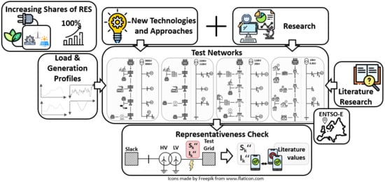
2. Methodology
This section presents the approach that was used to develop the test networks. Subsequently, each network is described individually in detail. The presented test networks in this work are developed for the 0.4 kV low-voltage level, the 20 kV medium-voltage level, the 110 kV high-voltage level as well as the 380/220 kV maximum-voltage level. In Austria, for example, there are various medium-voltage levels ranging from 1 to 36 kV. However, for now there is only a 20 kV-voltage level developed in this work. Each network is modelled using the network planning and network simulation software NEPLAN [
66].
The approach for test network development in this work was based on detailed literature research in order to identify the specific properties regarding European ENTSO-E electrical infrastructures, of which the Austrian structures are a part, without including sensitive user-specific information. A flowchart of the development process for the presented networks can be found in
Figure 2.
First, extensive literature research was conducted on European networks and their corresponding parameters. The literature values considered in this research for representing European network structures included system sizes (number of nodes), network topologies (radial, ring and meshed structures), electrical line types (overhead lines or cables), electrical line parameters (
R’, L’, C’, length) as well as generation and consumer units corresponding to the voltage level regarding their type and power range. Each parameter either represented an average value for European electrical networks (e.g., specific electrical line parameters
R’, L’, C’) or a typical range within which the values were chosen (e.g., electrical line lengths, generation and consumer power). Literature references for these parameters were taken from a variety of sources, some of which complemented each other and some of which overlapped [
67,
68,
69,
70,
71]. Therefore, the network parameters of the presented test networks described below represented a summary of the parameters found in the literature [
67,
68,
69,
70,
71]. Second, the test networks were developed in NEPLAN for different network structures regarding topology, network size and switching states. This offered a graphical representation of the network. Third, based on this NEPLAN model of each voltage level, the network dimensioning could be conducted. This included the definition of a rated apparent power as well as common transformer loadings for the substation transformer. Then, static power values (momentary power values for one time step) for the consumer and generation units were randomly chosen within the power ranges derived from the literature research. They represented maximum total values of the sum of load and generation profiles connected and aggregated in one network node. The researched static values were only used for an initial dimensioning of each network, thus assessing correct line and transformer loadings as well as voltage stability. Therefore, if the previously defined transformer loadings were not exceeded due to the chosen static consumer and generation power values, the grid could be operated in normal operation without transformer congestions over time. Then, line loadings and voltage limit stability were checked. If lines were congested, stronger lines were utilized (e.g., first line at the beginning of a feeder). If voltage limit exceeding occurred at certain network nodes, either generation (upper voltage limit exceeding) or consumer (lower voltage limit exceeding) powers were reduced. If errors no longer occurred, time-series based calculations using load and generation profiles could be conducted. Regarding the time series-based calculations, corresponding load and generation profiles from Austrian grids were chosen.
Figure 3 provides an overview over the test networks created in this work; they are described more in detail individually within the corresponding section. Generally, each network represented a balanced three-phase system.
2.1. Low-Voltage Level (0.4 kV)
The low-voltage test network is comprised of 92 network nodes with 91 connected consumer units as well as 39 connected generation units. The network topology represents a radial structure with 14 feeders including urban as well as suburban network structures. In the urban network structures there are shorter line lengths (0.02–0.18 km), but higher load densities, since each consumer unit consists of several residential units. In the suburban network structures there are larger line lengths (0.15–0.5 km) and lower load densities, since each consumer unit represents only one residential unit. Residential units within the grid were either defined by synthetic load profiles (created using a load profile generator [
72,
73]) or standard load profiles. Which profile was used was defined by the simultaneity curves [
74]. These enabled a realistic network design at the low-voltage level. Simultaneity factors take into account that the predefined static maximum load values of consumers do not occur at the same time, so that the network is not burdened with the sum of the maximum loads of all consumers in normal operation. Depending on the predefined static maximum power, the number of residential units per connection point is calculated using the given installed power of a single residential unit. The corresponding simultaneity factor can be taken from the diagram provided in [
74]. This allowed realistic static values to be obtained for network dimensioning. As a result, depending on the number of residential units within one connection point, it was then decided whether standard load profiles or synthetic load profiles were utilized. In the LV test grid, there were 207 households that were represented by different synthetic profiles or the standard load profile H0 (if the number of residential units in one grid connection point was high enough), which are explained in
Table 6. Additionally, there was a total of 17 commercial businesses represented by standard load profiles (4 G0, 4 G1, 1 G2, 1G3, 2 G4, 4 G5 and 1 G6) as well as a total of 6 agricultural businesses also represented by standard load profiles (2 L0, 2 L1 and 2 L0). The 39 generation units exclusively represented private PV-systems, which were defined by a synthetic generation profile created using a solar energy model developed at the Chair of Energy Network Technology, which is based on irradiation data and rooftop areas at the corresponding residential units. A more detailed itemization of the used synthetic and standard load and generation profiles can be found in
Table 6.
Within the low-voltage test network, there were 92 electrical lines with a total electrical line length of 5.931 km and single line lengths ranging from 0.02 to 0.45 km. Regarding the electrical line types within the test network, three different cable types were applied. Since the first line section supplying each feeder had to enable transmission of high loads and normal operation did not provide closed ring structures to partially supply consumer units at the end of the feeder, a stronger line type (NYY 4 × 300) was selected for some feeders. The remaining line sections within the test network corresponded with a cable type with average specific line parameters (NAYY 4 × 185 for urban structures and NAYY 4 × 150 SE for suburban structures) for European grids at the low-voltage level.
Table 7 shows the used cable types and their electrical line parameters.
The transformer in the local substation was a three-phase transformer with a rated apparent power of 630 kVA feeding the low-voltage network from the 10 kV-medium-voltage level. The vector group chosen for the substation transformer was Yz5, which is common for smaller distribution transformers, since unbalanced loads can occur, especially on the lower-voltage side, and balancing is achieved due to the neutral point.
Table 8 shows the parameters of the transformer used.
Figure 4 shows the described low-voltage test network developed in NEPLAN.
2.2. Medium-Voltage Level (20 kV)
The medium-voltage test network represented a public power distribution grid comprised of 74 network nodes with 64 consumer units and 15 generation units. Consumer units were represented by the load profiles of 7 different local substations available at Chair of Energy Network Technology, as well as commercial standard load profiles with higher annual energy consumption, since, for example, large feeding water pumps may also be directly connected at the medium-voltage level (standard load profiles G2, G3 and G6; cf.
Table 6). The generation units either represented wind power units, solar power plants, biomass plants, geothermal power plants or run-of-river power stations. The data for these generation units, except for the wind data, originated from measurements of the Austrian control area operated by the APG (Austrian Power Grid), publicly available at the APG homepage [
75]. These data were then scaled down to represent a generation unit at this voltage level, since the original data represent a cumulative generation profile of each generation type for Austria. The wind data represent measured data from parts of Austria. Since the measured wind data from APG were aggregated data for all wind plants in Austria, fast start-up rates were no longer displayed within the profile due to this aggregation. Therefore, this data would no longer represent the real strain wind generation puts on the grid, since there are no fast load changes due to the flattened profile of the aggregated wind power plants. To represent real grid burdens, the measured data were used for only a couple of wind power units within the test networks.
The network topology of the medium-voltage grid is a radial structure with 2 permanently closed rings during regular operation and 11 open ring lines, which do not transmit power during normal operation. These electrical lines can be closed in the event of a fault and, thus, ensure that consumers affected by the fault are supplied via a different current path. This network topology is, therefore, referred to as an open ring structure, which is common for European medium-voltage structures. The medium-voltage test network, therefore, consists of 18 feeders.
Within the medium-voltage test network there are 86 electrical lines, of which 11 are operated in an open mode; therefore, 75 electrical lines transmit power in normal operation. This results in a total line length of 730.98 km with line lengths ranging from 1 km to 20 km. The chosen line type represented a cable that corresponded with the average specific electrical line parameters at this voltage level, which are shown in
Table 9.
The transformer in the transformer substation is a three-phase transformer with a rated apparent power of 50 MVA feeding the medium-voltage network from the 110 kV-high-voltage level using a Dy5 vector group, which is common for large distribution transformers in Europe. The neutral point is fully loadable, thus avoiding additional losses and neutral point shifts, which is advantageous in high current environments.
Table 10 shows the parameters of the transformer used.
Figure 5 shows the described medium-voltage test network for European grids designed in NEPLAN.
2.3. High-Voltage Level (110 kV)
The high-voltage test grid consists of 70 network nodes with 69 consumer units and 18 generation units. The consumer units are defined by the load profiles of 27 different transformer substations available at the Chair of Energy Network Technology that supply the subordinate medium-voltage levels. The generation units represent wind power units, gas and coal power plants, as well as run-of-river power stations and discharging of storage units. The data for these generation units, except for wind power data, were also collected from measurements of the Austrian control area operated by the APG, publicly available at the APG homepage [
75], and then scaled down to represent a generation unit at the high-voltage level. The wind data represent measured profiles in parts of Austria, as described within
Section 2.2.
The network topology of the high-voltage test grid consists of 6 feeders and represents a closed ring structure including some redundant, open electrical lines, which can also be closed in case of a fault. Closed ring structures at this voltage level enable the transmission of larger loads and increase the security of the supply.
Within the high-voltage test grid there are 89 electrical lines, of which 12 lines are operated in an open mode during normal operation; therefore, the remaining 77 lines transmit power in normal operation with a total line length of 1477 km that includes electrical line lengths ranging from 8 km to 30 km. The electrical line type chosen for this test network was an overhead line with average specific line parameters. In this test grid, no underground cables were considered.
Table 11 shows the characteristics of the chosen overhead line type.
The transformer in the transformer substation is a three-phase transformer with a rated apparent power of 800 MVA feeding the high-voltage network from the 220 kV-maximum-voltage level. The chosen vector group for this transformer was Yy0, which is common in European transportation grids.
Table 12 shows the parameters of the transformer used.
Figure 6 shows the described European high-voltage test network designed in NEPLAN.
2.4. Maximum-Voltage Level (380/220 kV)
The maximum-voltage test network consists of 19 network nodes, of which 7 belong to the 380 kV voltage level and the other 12 belong to the 220 kV voltage level. There are 2 consumer units within the 380 kV voltage level, which represent substations feeding the 110 kV voltage level. Within the 220 kV voltage level network there are 12 consumer units also representing substations feeding the 110 kV voltage level network. In total there are 10 generation units, 5 at the 380 kV voltage level and 5 at the 220 kV voltage level. The data for the consumer units represent the sum of a different number of load profiles of transformer substations feeding the medium-voltage level from the 110 kV voltage level available at the Chair of Energy Network Technology. The generation units represent wind power generation, gas or coal power plants, run-of-river power stations as well as pumped-storage plants. The data for the generation units were also taken from the APG homepage [
75]. The wind data represent measured wind data from parts of Austria, as well as at the medium- and high-voltage level.
The network topology for the maximum-voltage grid represents a meshed structure with only very few open ring structures. This enables the transmission of greater loads and the power supply from large power stations.
The maximum-voltage level consists of 24 electrical lines, of which 5 lines are operated in an open mode during normal operation. Of the remaining 19 lines, 7 lines belong to the 380 kV-level and 12 lines belong to the 220 kV-level. The total line length of the entire 380 kV- and 220 kV-voltage level is 931.2 km, with 364.7 km at the 380 kV-voltage level and 566.5 km at the 220 kV-voltage level. The electrical line lengths range from a minimum of 10 km to a maximum of 75 km. The electrical line type chosen for this test network was an overhead line with average specific line parameters for the corresponding voltage level. Again at this voltage level, no underground cables occur, which is common for European electrical structures.
Table 13 and
Table 14 show the characteristics of the chosen overhead line types.
Since there are two voltage levels within this test network, there are also transformer stations that connect the two voltage levels. There are 5 transformer stations connecting the 380 kV-level with the 220 kV-level. Each transformer station represents a three-phase transformer with a rated apparent power of 1200 MVA using a YNyn0 vector group. This vector group is commonly used for large dome transformers.
Table 15 shows the parameters for each transformer substation.
Additionally, there is one transformer at the 380 kV-level representing the Slack-node, which either represents the exchange of power at the same voltage level or the exchange of power with a higher voltage level. For Austrian grids this also represents the exchange with another control zone of the surrounding country. In this test network, the Slack-node-transformer represented the exchange of power with another 380 kV-voltage level grid and was responsible for isolating the two networks. The rated apparent power of this transformer was 10 GVA, and the chosen vector group was Yy0, which are common in European transportation grids.
Table 16 shows the parameters for the Slack-node transformer.
Figure 7 shows the described maximum-voltage test network created in NEPLAN. This test network was based on the actual Austrian maximum-voltage level grid, which can be found on the Austrian Power Grid (APG) homepage [
76]. This test network consisted of 5 feeders.
Table 17 offers an overview of the presented test networks developed in this work, including the network specific parameters.
3. Results
This section presents the results obtained from performing a short-circuit analysis on each of the presented networks and comparing these results with literature data. This provides support in validating the representativeness of the networks. The short-circuit power value is a measure of voltage quality and interference resistance of a power system and, thus, the behavior of a network. As a result, the short-circuit power can be influenced by various factors, such as the number of synchronous machines within the network, the degree of meshing (including switching states) or inductance coils for power factor correction. Structural aspects of the network can be assessed via the short-circuit current, since this is mainly influenced by the number of parallel branches and, thus, directly depends on the short-circuit impedance. Therefore, this analysis showed how well the generic test networks presented replicated real network behavior [
68].
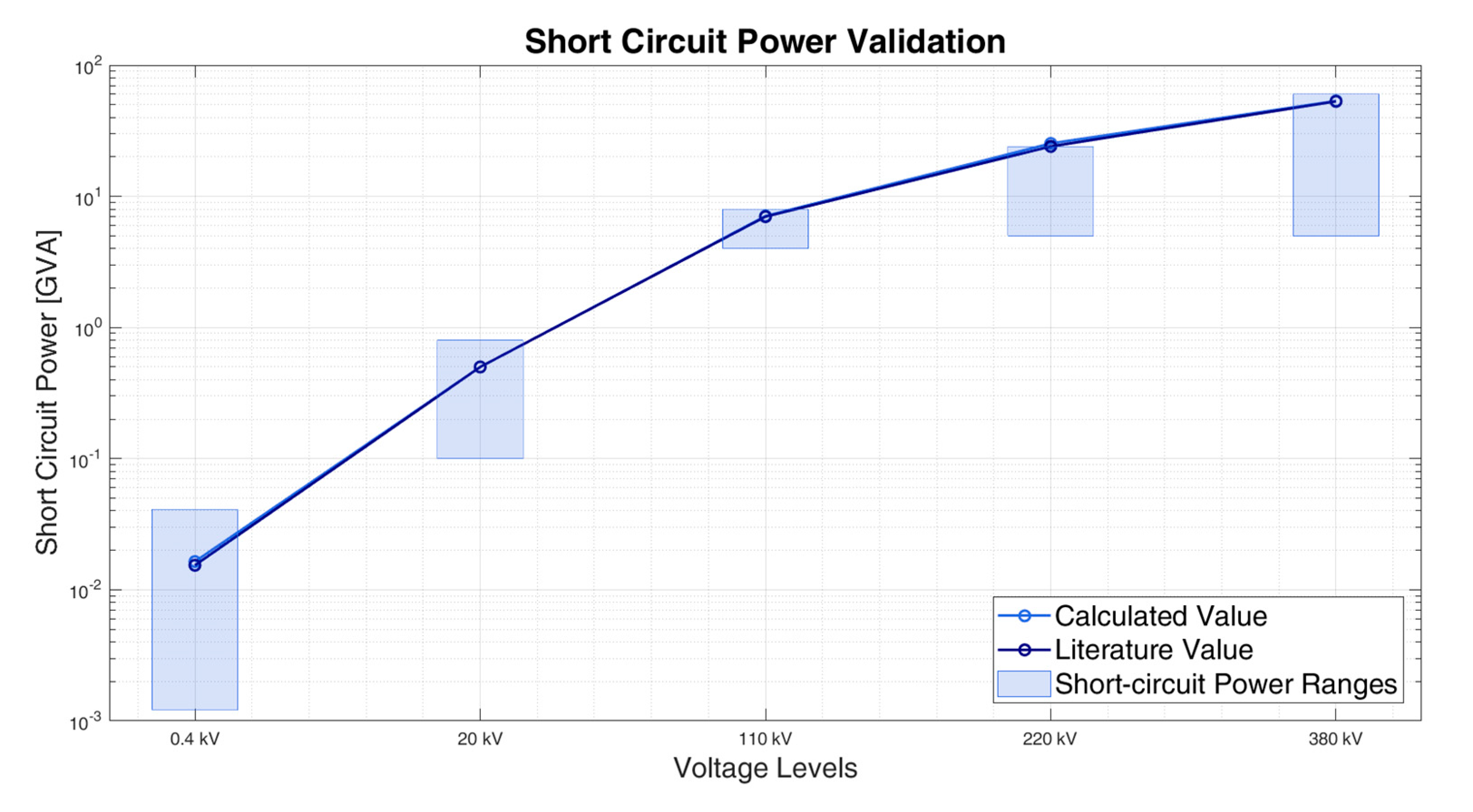
For that purpose, literature values for German grids, which are very similar to Austrian grids, as well as value ranges for European grids at each voltage level were found. Therefore,
Table 18 shows the researched literature value ranges for European grids regarding short-circuit power as well as short-circuit current. The value ranges presented in
Table 18 are also depicted in
Figure 8.
Table 19 compares the calculated values of the short-circuit power for each voltage level with those found in the literature for German grids. Both are graphically depicted in
Figure 8. Additionally,
Table 19 shows the relative and absolute deviations between the literature values and the calculated values. The deviations were calculated according to Equations (1) and (2). A positive (absolute and relative) deviation suggests that the literature value is higher than the calculated value.
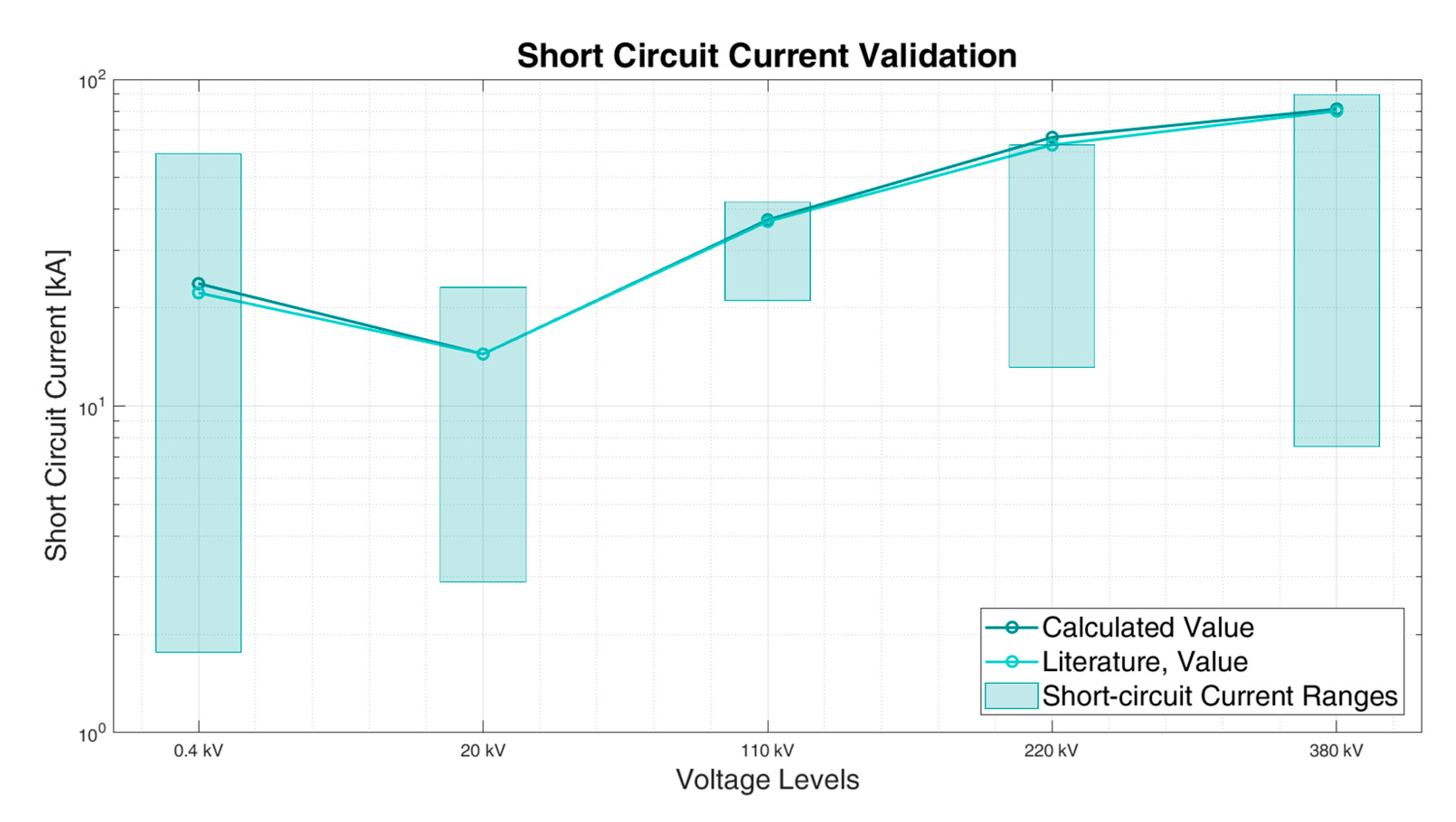
In order to fully validate the developed generic test networks presented in this paper, the short-circuit currents were also taken into account. Therefore,
Table 20 compares the calculated values of the short-circuit current for each voltage level with those found in the literature for German grids. Both values are graphically depicted in
Figure 9. Additionally,
Table 20 shows the relative and absolute deviations between the literature values and the calculated values for the short-circuit current. The deviations were also accordingly calculated as presented in Equations (1) and (2).
4. Discussion
Within this section, first the results regarding the comparison of the short-circuit parameters presented in
Section 3 are addressed. Second, the previously mentioned limitations (
Section 1.2) are discussed for the presented test networks. This will show how most of the limitations for the presented test networks within the literature review can be compensated in the presented test networks, but also reveals their limitations.
4.1. Short-Circuit Results
Table 19 and
Table 20 as well as
Figure 8 and
Figure 9 show that, in general, the presented generic test networks can be used to represent the behavior of real European networks. The reference values from the literature in
Section 3 represent German grids, and the value ranges from the literature represent European grids. Since German and Austrian grids are substantially similar and no literature data was available for Austrian grids, these values were used as reference values in this work. However, this may lead to slight deviations for the short-circuit parameters, as can be seen in
Figure 8 and
Figure 9. Individually, there are some test networks that offer better replication of real network behavior than others, which will be discussed in the following.
The low-voltage test network shows a −6.75% relative deviation between the German literature value and the calculated value for short-circuit power. The relative deviation of the short-circuit current corresponds with −6.70%, therefore suggesting that the low-voltage test network may not be sufficiently representative for all applications, since both the short-circuit power as well as the short-circuit current are higher than the literature values. A higher short-circuit power, however, would suggest better voltage quality as well as greater interference resistance within the power system. Therefore, the real behavior of the grid would not be replicated properly. One parameter influencing the short-circuit values is the network structure, which for low-voltage networks mainly refers to whether they supply urban, suburban or rural areas. This network supplies mainly urban and only partially suburban as well as rural areas. Since there is no indication of the network structure for the German literature values, this may also be a cause for higher deviations. Another parameter on which the short-circuit values are dependent is the apparent power of the substation transformer feeding the network. If the rated apparent power of a substation transformer is smaller, short-circuit values are smaller as well. Since, however, there is no detailed information on the grids used for obtaining the corresponding literature values, these factors may be causes for the deviation. At the Chair of Energy Network Technology, a similar test network with primarily rural structures fed from the 10 kV-voltage level with 50 kVA rated apparent power (cf. the presented low-voltage network fed from the 20 kV-voltage level with 630 kVA rated apparent power) was developed and tested and produced short-circuit values which approximated the corresponding literature values more closely. However, the presented value range for low-voltage short-circuit power in European grids, which is between 1.2 and 41 MVA, matches the calculated values. Since the corresponding calculated value for the low-voltage grid is 16.42 MVA, the presented low-voltage test grid may replicate real network behavior of European grids sufficiently accurately.
The 20 kV medium-voltage test network shows a relative deviation of 0.07% for the short-circuit power and 0.04% for the short-circuit current. Therefore, the calculated values closely approximate German grids and, thus, also European grids. This suggests that although there is a large variety of medium-voltage grids regarding voltage levels as well as system sizes and network structures, the presented networks replicate European as well as German grids well. Therefore, they offer a valuable contribution to the research community in representing the diversity of medium-voltage grids. Since short-circuit current deviations are small (0.04%), the structure of real grids regarding parallel feeders within a medium-voltage grid is replicated especially well in this test network.
The higher voltage levels (110 kV, 220 kV and 380 kV) also show small relative deviations in short-circuit power of −1.08%, −5.49% and −0.73%. The relative deviations for short-circuit currents are similar, with values of −1.08%, −5.46% and −1.39%. Additional deviations at these voltage levels may be caused due to the lack of reactive power compensation elements (e.g., inductance coils for power factor correction). These components are important elements for energy transmission at higher voltage levels and, therefore, also influence the replication of the network behavior. Additionally, the short-circuit power at this voltage level is influenced by switching states and, thus, the resulting degree of meshing. With high degrees of meshing and fewer openly operated electrical lines, the short-circuit power increases. Since there is no detailed information on the literature values, it is possible deviations partially also occur due to different researched switching states.
4.2. Limitations of the Presented Test Networks
Since most test networks from the literature review may not be large enough for some applications, the presented generic test networks represent common network sizes for Austrian grids typical for a network of a single voltage level fed from the higher voltage level via a transformer. For the lower voltage levels (low-, medium- and partially high-voltage), common network sizes are derived from previous experiences with real grids at the Chair of Energy Network Technology. For higher voltage levels (partially high- and maximum-voltage) the common network sizes are publicly available. Additionally, appropriate network sizes also depend on the application purpose; smaller sizes may also be sufficient to assess several research questions.
Regarding the lack of time-series data, the presented test networks include Austrian load and generation data as well as standard load profiles, which can be exchanged for different profiles for different time periods or different consumer and generation units.
The representativeness of the proposed generic test networks for European structures can be assessed from the short-circuit validation. Since the presented test networks are specifically aimed at representing European ENTSO-E structures, the mentioned parameters were researched and chosen accordingly, which is affirmed by the validation process using short-circuit parameters.
Although the presented test networks do not include geographical coordinates, since they are generically obtained from literature research, they are designed in NEPLAN and, therefore, offer a graphical representation of the network and the included components.
Another limitation addressed in
Section 1.2 is that most designs and data are specific for one single issue. The test networks presented in this work are designed for replicating European network structures and their behavior, especially, for load flow calculations. If, however, other issues are addressed, these networks may be extended as required. Additionally, the fact, that these test networks are available in NEPLAN means that network parameters as well as network equipment can easily be changed or modified.
Many of the presented (mainly the North American) test feeders are limited in their use due the fact that they only represent isolated feeders and, therefore, are not capable of replicating the behavior of an entire network. On the contrary, each of the developed networks replicates one voltage level with corresponding network sizes. Therefore, each network represents more than one feeder.
5. Conclusions
This paper presents generic test networks for the European electrical distribution and transmission system. The aim is to closely replicate the network behavior of real grids at each voltage level. Since in the literature only very few representative test networks are available for European grids, new test networks with specific parameters for the European ENTSO-E interconnected system are developed, thereby ensuring a replication as accurately as possible. Since data for grids are usually sensitive due to the included consumer data and are, therefore, not disclosed by distribution and transmission system operators, only the openly available data in the literature were used to design the test networks. The researched parameters include network topologies, load densities, power ranges, types and number of consumer as well as generation units, electrical line data (line length ranges and electrical line parameters) as well as network sizes. Thus, four test networks of each voltage level common in Europe (0.4 kV, 20 kV, 110 kV, 220/380 kV) were developed.
In order to validate the presented test networks regarding their representativeness of European grids, a short-circuit analysis was performed on each test network. The results obtained from this analysis (short-circuit power and current) were then compared to literature values common in Germany and Europe. This analysis showed that the created test networks can replicate European network behavior closely. Additionally, these test networks have very few limitations and can be used for various application purposes.


