1. Introduction
A heat pipe with a very high thermal conductance is an efficient passive heat transfer device. In a heat pipe, a small quantity of working fluid is charged in a metallic vacuumed container, and the tube is sealed. One side end of the tube, the evaporator, is heated, and the liquid vaporizes, which induces the movement of the vapor to the other end of the tube, the condenser. In the condenser section, the condensate liquid is then returned to the evaporator section by capillary driven liquid circulation continuously as long as heat is applied. A large amount of heat from this phase change process can be transferred for certain purposes such as cooling, heating, or energy usage with a small temperature difference between the evaporator and condenser. So far, various heat pipes have been adopted and tested as efficient heat transferring devices in many demanding applications such as energy transfer, electronics cooling, and space application [
1,
2,
3,
4]. However, the current annular heat pipe heat sink (AHPHS) concept for electronics cooling has an unconventional structure, where the cross-section of the vapor space becomes annular and has a three-dimensional flow to accommodate uneven liquid motion, unlike previous annular heat pipes for dryers or furnaces [
5,
6,
7].
The main difference between the AHPHS and the conventional heat pipe is that the cross-section of the annular vapor space is an annulus, which in the AHPHS results in a large heat transfer surface area for heat input and output without increasing the outer diameter of the pipe. The annular shape heat pipe is not a common structure in the literature but has been tested in an isothermal furnace system, among others. It is obviously clear that there are many gaps in concentric annular heat pipe (CAHP) research. Specifically, the annular type of heat pipe has a limited application in certain devices because of difficulties in terms of defining heating and cooling position or area. These difficulties are induced from the presence of the center space of the inner tube rather than the annular space [
8,
9]. Faghri and Thomas [
8,
9] investigated a CAHP of a copper container and used water as the working fluid. Their CAHP and conventional heat pipe with a similar outer tube diameter showed excellent heat transfer performance, with a 1.85-fold increase (700 to 1300 W). Many configurations were reviewed and suggested by Boo and Park [
10]. They suggested that the entire axial length of the center space can be the evaporator for the heating of the drum, where isothermal heating occurs throughout the whole inner surface area. They reported the effects of diameter ratio (2.31 to 4.23) between the outer and inner tube of the CAHP and the effect of working fluid filling charge ratio from 20% to 100% on the isothermal and transient behavior. They reported that the axial temperature difference was just 1 K compared to a copper block (6 K) with the same outer dimension. Time lag was not observed in the temperature response test between the CAHP and the heat source; in addition, there was a 25-min lag for the copper block. Although the overall thermal performance was improved by increasing the inner diameter ratio with a fixed outer dimension, it was reached that the effect of the filling ratio was more pronounced than the diameter ratio.
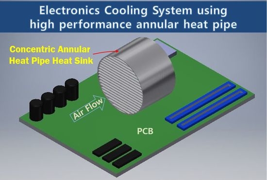
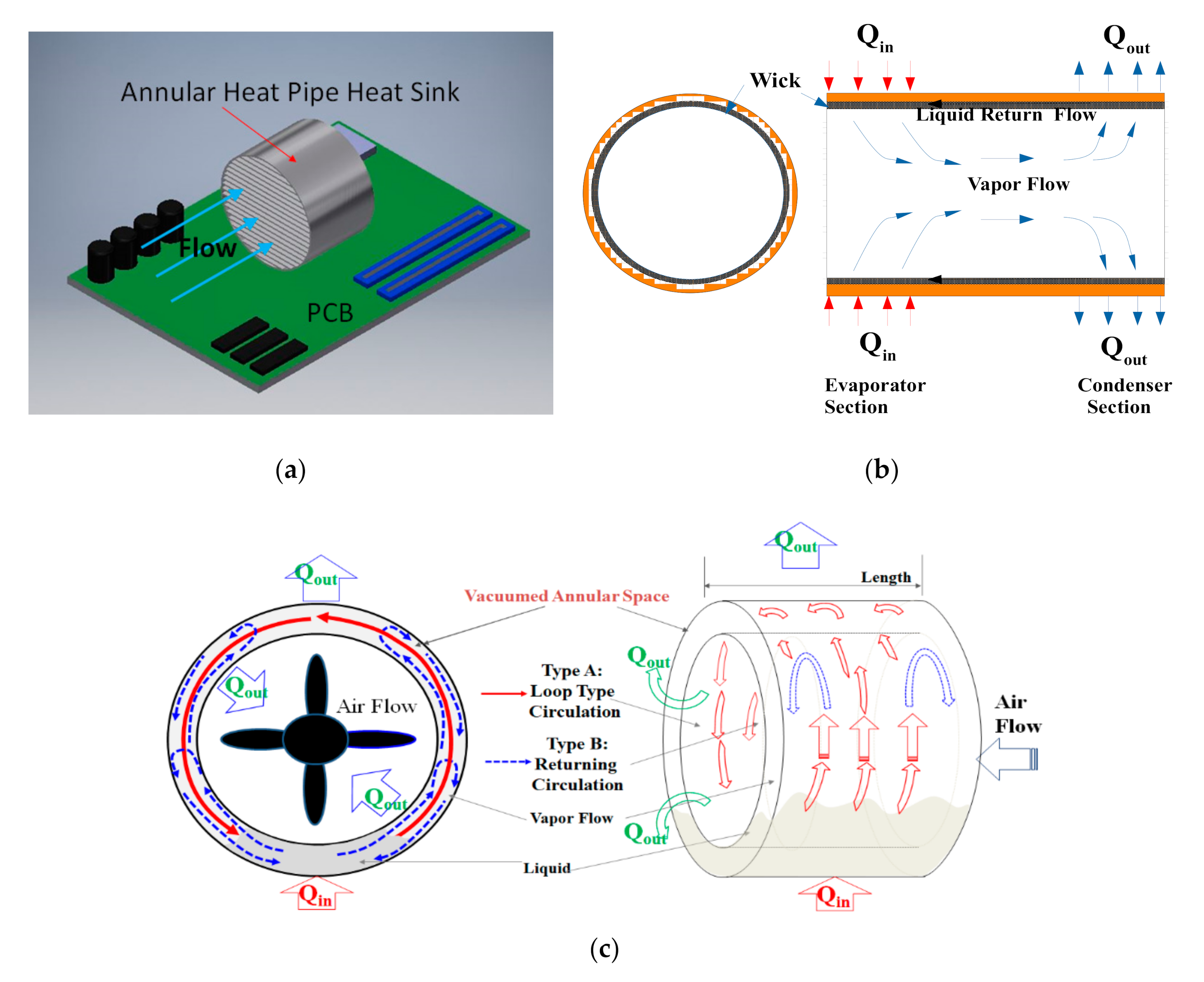
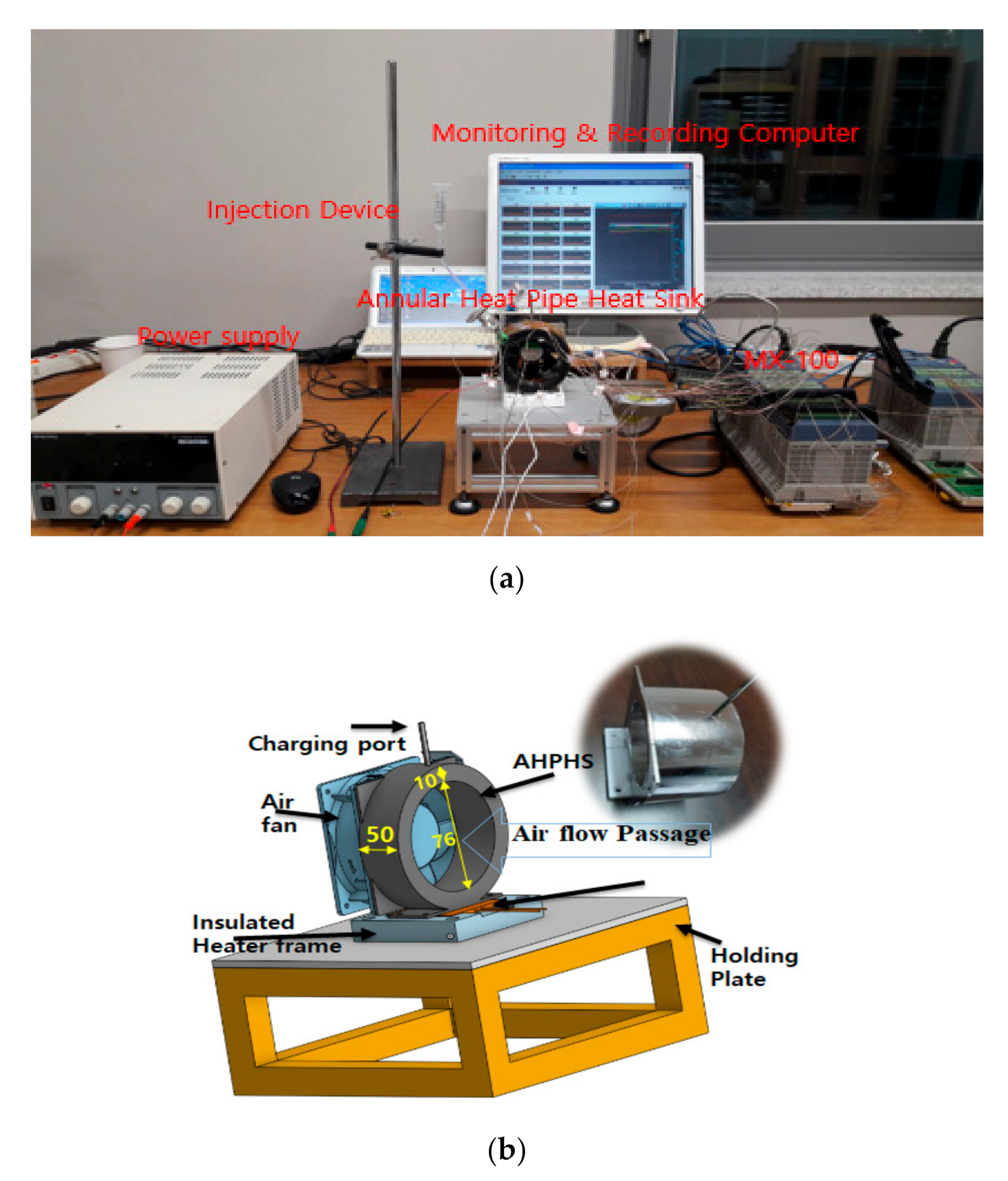
As shown in the concept design of
Figure 1a,b, the concentric annular heat pipe was proposed for electronics cooling. The current annular heat pipe consists of the annular cross-section of the vapor space. A novel concept deriving from the concentric annular heat pipe (CAHP) requires the understanding of the annular design, which differs in the heating and cooling section from the conventional heat pipe. Influencing parameters affecting the thermal performance of the AHPHS include the working fluid, charging rate, wick structure, annular space ratio, and material. The main difference between the CAHP and conventional heat pipes is the annular cross-section of the vapor space, as opposed to a circular cross-section. Therefore, it is possible to customize the surface area of heat input and output to improve the thermal performance. Unfortunately, this type of heat pipe is uncommon in the literature as well as in industrial applications [
8,
9,
11,
12,
13]. Yan et al. [
12] reported an excellent temperature flattening ability using annular sodium heat pipes operating from 500 to 1200 °C. Their experimental results showed that the largest temperature difference within 150 mm at the bottom of the thermometer is better than 15 mK in the aluminum point cell installed in the sodium heat pipe furnace, which was controlled to about 657 °C. Choi et al. [
13] investigated a concentric annular heat pipe with almost half area heating. Their work presents an isothermal, low-temperature (200–300 °C range) heat pipe furnace for a metallic nanoparticle sintering process. Inner center space was used as the sintering process space to achieve uniform heat distribution. Naphthalene was used as a working fluid to satisfy the design temperature. The furnace tests showed stable startup and steady-state operation. The temperature distribution measurement of the furnace demonstrated a uniform temperature zone, where the temperature variance was within ±1 °C. To demonstrate the functionality of the furnace, the surface of the microporous wick was sintered by nanoparticles. Vijra and Singh [
14] investigated the stainless steel/water CAHP with various thermal inputs from 50 to 300 W and with different conditions with directional angles (0°, 45°, and 90°) and a horizontal state. They reported that the minimum temperature difference from the evaporator to the condenser was 3 K with the best operation conditions. Kammuang-lue et al. [
15] reported the thermal behavior of annular thermosyphon fabricated with three concentric tubes of different diameters. A vacuum-sealed annular passage with different diameters between the inner tube and outer tube was filled with a certain amount of working fluid. They concluded that annular thermosyphon is more suitable for heat releasing applications than conventional thermosyphon.
A current annular heat pipe consists of two concentric tubes with different diameters with the smaller and larger diameter tube positioned in an annular shape, and both ends are sealed tightly. Usually, wicks are attached on both inner surface areas to aid vapor and condensate return flow. The space inside the inner tube and outer surface outside tube is exposed to the surroundings as the cooling surface. In earlier studies, it was reported that the CAHP provides a larger surface area for radial heat flux compared to the conventional heat pipes. Larger possible heat transfer area can lead to increase in heat transport capacity [
8,
9,
11]. Kim et al. [
16] reported the visualization study in the vertical upward annular thermosyphon. They tried to find the difference from conventional thermosyphon and reported the annular thermosyphon is dominated by wall shear viscosity force than the buoyance force. Mustaffar et al. [
17,
18] presented a new configuration of a 515 mm-long stainless steel CAHP with an outer diameter of 76.2 and inner diameter of 38.1 mm. Their entire inner central space of the tube was specified as the condenser. Through this central space, wet ceramic slurries were conveyed to reduce moisture with energy reduction. A screen wick was attached on the inner wall surface of the outer tube. Angular orientations of 0–90°, filled volume ratios of 11–43% and input heat rates of 272–302 W were investigated experimentally. The authors reported that the filling of 11% was the optimum amount of working fluid to sustain an excellent isothermal operation. They reported that the calculated global thermal resistances were 0.08–0.31 K/W. Zhao et al. [
19] reported the high temperature annular heat pipe with anti-gravity condition. Their application is also similar structure to keep uniform temperature along axial length. They reported the frozen start-up test with different inclination angles. Recently, Faghri [
20] introduced review on various heat pipe including annular heat pipe. He reported that the application of annular heat pipe is limited to the high temperature furnace, but this type of heat pipe has enough potential for new applications.
2. Experiment
As shown in
Figure 2a,b and
Figure 3, the outer tube of the AHPHS had 100 (
D+ = 1.3) and 84 (
D+ = 1.1) mm outer diameters, while the inner diameter tube was same 76 mm with 2 mm thick stainless steel (outer/inner tube diameter ratio,
D+ = 1.1 and 1.3). In addition, as shown in
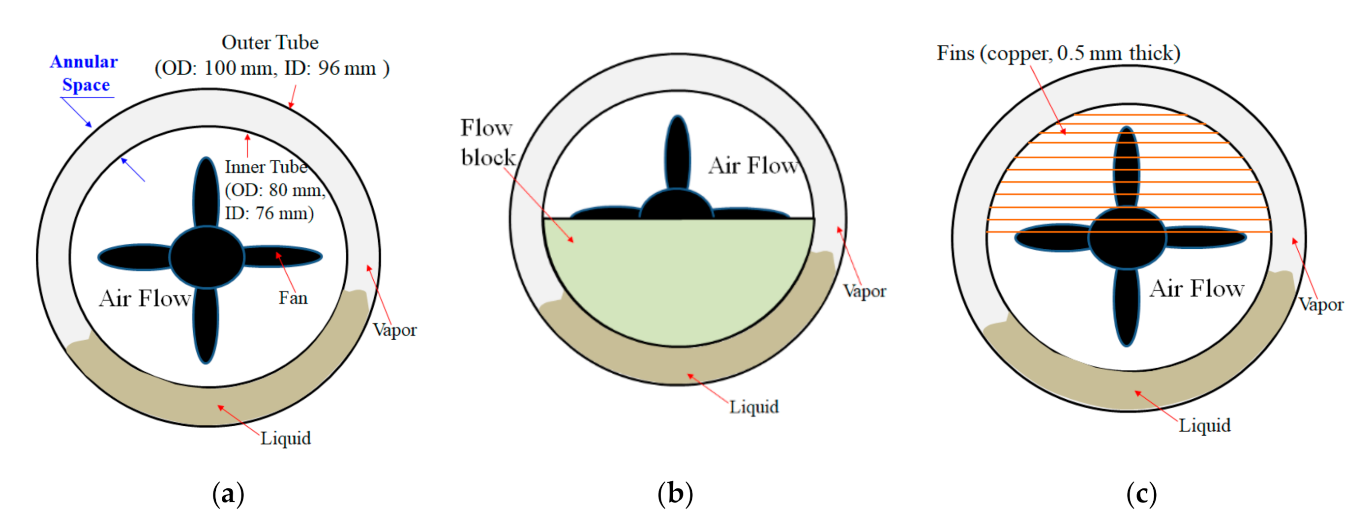
Figure 4, the internal concentric surface was designed as three types of flow passage such as a bare circular flow passage (Model A,
Figure 4a), Model B (
Figure 4b) accompanied with half blocked passage and Model C (
Figure 4c) with a finned surface to increase convective cooling through center passage of an AHPHS of
D+ = 1.3. The cooling medium was bypassed through the concentric area of the AHPHS from 1 to 4 m/s. The material of the container is stainless steel. Both ends of two concentric tubes were welded with end plates to create a vacuumed sealed container; the smaller diameter tube was placed in the inner space of larger diameter tube. After vacuuming, it contained a certain amount of working fluid defined as the filling ratio of charged volume space from 10% to 80%. Deionized water, FC-72, and methanol were used as the working fluid. The fluid was injected by syringe into the AHPHS with a perfect vacuum of 10
–5 torr. The minimum scale of the charging syringe was 0.01 mL. The volume fraction of working fluid, VF, is considered the ratio between total volume and filled volume of working fluid.
A special 50 × 50 mm flat heater with heating wire was installed. The outer tube was used to create an evaporator section of 50 mm in length. The entire length of the center space was designated as the condenser. As shown in
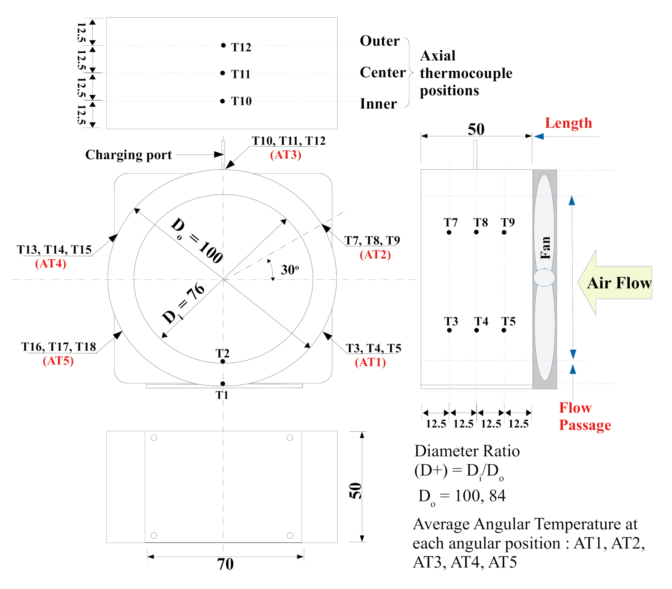
Figure 3, 0.25 mm diameter K-type thermocouples were placed along the axial and radial length of the outside surface of outer tube, inside the annular vapor space and the center space as shown in
Figure 3. As shown in
Figure 3, a total of 20 thermocouples were installed to measure the two-phase flow behavior. At the same angular position, average temperatures from three axial thermocouples were used to investigate the liquid circulation feature. Temperature was recorded continuously with given time step using a data acquisition system (Yokogawa MX-100) and stored in a computer as shown in
Figure 2a. The accuracy of temperature measurement was ± (rdg 0.05% + 0.7%).
Figure 3 shows dimensional view of the current AHPHS and thermocouple positions installed. As shown in
Figure 3, thermocouple positions 3–18 were on the same axial line, and six radial positions of 30° angular division were located on the outer surface. Position 1 was located in the bottom and of the evaporator, position 2 in the upper and inner surface part of the evaporator surface, and position 20 in the upper-inner surface of the condenser section. We used a DC power supply to adjust the power of heater; the minimum scale of the ammeter and voltmeter was 0.01 A and 0.01 V, respectively. A 50 mm × 50 mm heater was installed on the bottom of the AHPHS.
A degassing and charging valve tube were welded to the outside top of the outer surface to facilitate working fluid filling as well as to evacuate air via a vacuum pump. To estimate thermal performance of the present cooling system, the evaporator and heater temperature of the evaporator and supplied heat rate were determined from steady-state data.
Q is the heated power input supplied to the evaporator, which is defined as the calculation of Equation (1).
In the current experimental investigation, many sets of temperature, voltage, and current measurements were created. In experimental study, the uncertainty of each set of measurements may be expressed with the same odds. These measurements can be used to estimate a certain result of the experiments related to thermal performance. In the current experimental study, the uncertainty
U is a given function of the independent experimental variables
x1,
x2,
x3, …,
xn. Thus, this can be described as
U = U (x1,
x2,
x3, …,
xn) in terms of various variables related to the experiment.
wR is defined as the uncertainty in the experimental result, and
w1,
w2, …,
wn are the individual uncertainties of the independent variables. In Equation (1),
I and
V are the input current and voltage as variables, respectively [
21].
Experimental uncertainties of the direct measurement parameters were applied to the electric-power relation, such as
T,
V, and
I, which were synthesized by the system uncertainty and analyzed as thermal resistance shown in Equation (2) [
21]. In Equation (2),
wi and
w𝑅 are the partial and total uncertainty errors, respectively. According to the methods in Ref [
3,
21], the maximum uncertainty induced from power in this study was ±
%.
3. Methodology
To investigate thermal behavior related to heat transfer performance of the AHPHS, various parameters such as filling ratios, air flow velocity, diameter ratios, and supplied heat flux were tested using the AHPHS, which was specially designed and fabricated as described above. Tests were carefully performed to investigate the maximum stable heat transmission operation of the current heat pipe. The experimental work is outlined in
Table 1. These experimental variables influenced variables in terms of liquid circulation like conventional heat pipes even if liquid circulation geometry was different from other types.
In the AHPHS, stable and fast liquid circulation in vacuumed space is an important working characteristic. As shown in
Figure 1c, liquid/vapor circulation from the evaporator section to the condenser section is one of the main features of any kind of heat pipe. Therefore, in the present concentric annular heat pipe, the experimental parameters shown in
Table 2 were investigated to check the continuous circulatory working behavior with heat transfer performance. As shown in
Figure 1b, in the present experimental study, two types of flow circulation were observed: Type A, recirculating flow, and Type B, circulating flow. These circulating types are explained in a later section.
Thermal performance of any kind heat pipe system can be estimated by Equation (3), where
is temperature difference from the heat source to the sink in terms of the system. Alternatively, it can be estimated from the evaporator surface to the condenser surface in terms of the heat pipe. It can be different depending on what form of thermal performance is investigated [
2]. In the current AHPHS, the condenser surface cannot be specified as a small area. Therefore, thermal characteristics of the AHPHS were investigated, including angular temperatures and how inner working fluid affects dynamic circulatory operation with different heat flux and filling ratios.
To investigate circulatory liquid motion, average temperatures at angular positions were observed. Each angular temperature was averaged with three axial temperatures as described in
Table 2.
As mentioned above, working fluid amount is a key parameter to verify the optimum or stable working condition of the AHPHS. In a conventional heat pipe, optimum charged amount of working fluid is recognized in the range of 40–60% in terms of filling ratio occupied by working fluid [
1,
2]. In the current work, the effect of working fluid amount was calculated by volume ratio in terms of filled volume to the total volume inside the annular heat pipe, as shown in Equation (4).
As describe shown in
Figure 1c,
Figure 3 and
Figure 4, annular gap space between the inner tube and outer tube is another key parameter because the annular gap is the moving channel of vapor. Continuous vapor movement and circulation is the main criterion for enhancing heat transfer performance in a heat pipe. Therefore, the effect of annular gap space was investigated using diameter ratio as shown in Equation (5).
4. Results and Discussion
In the current experimental study, as mentioned above, various parameters were investigated to improve thermal performance of an AHPHS. The filling ratio, supplied heat, various flow passages, coolant speed, and different diameter ratios were the studied parameters, and an additional thermal image for visual study is presented.
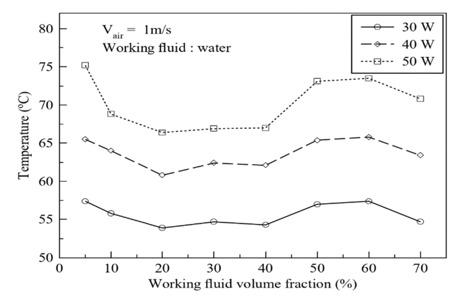
4.1. Effect of Charged Ratio (VF)
The working fluid charged volume compared to the total internal volume as the filling ratio (
D+) is an important experimental parameter in the optimization of a heat pipe. For an AHPHS, the optimum charged amount is important for continuous liquid circulation. The reason is that heat pipes usually work under an internal vacuum state, and, therefore, the heat pipe should be welded after charging an optimum amount of working fluid. After the system was welded for vacuum sealing, the working fluid amount could not be changed. Experimental work with a varying amount of working fluid is the only practical approach for investigating a heat pipe’s performance on the filling ratio. In the lab test, the fluid could be underfilled or overfilled.
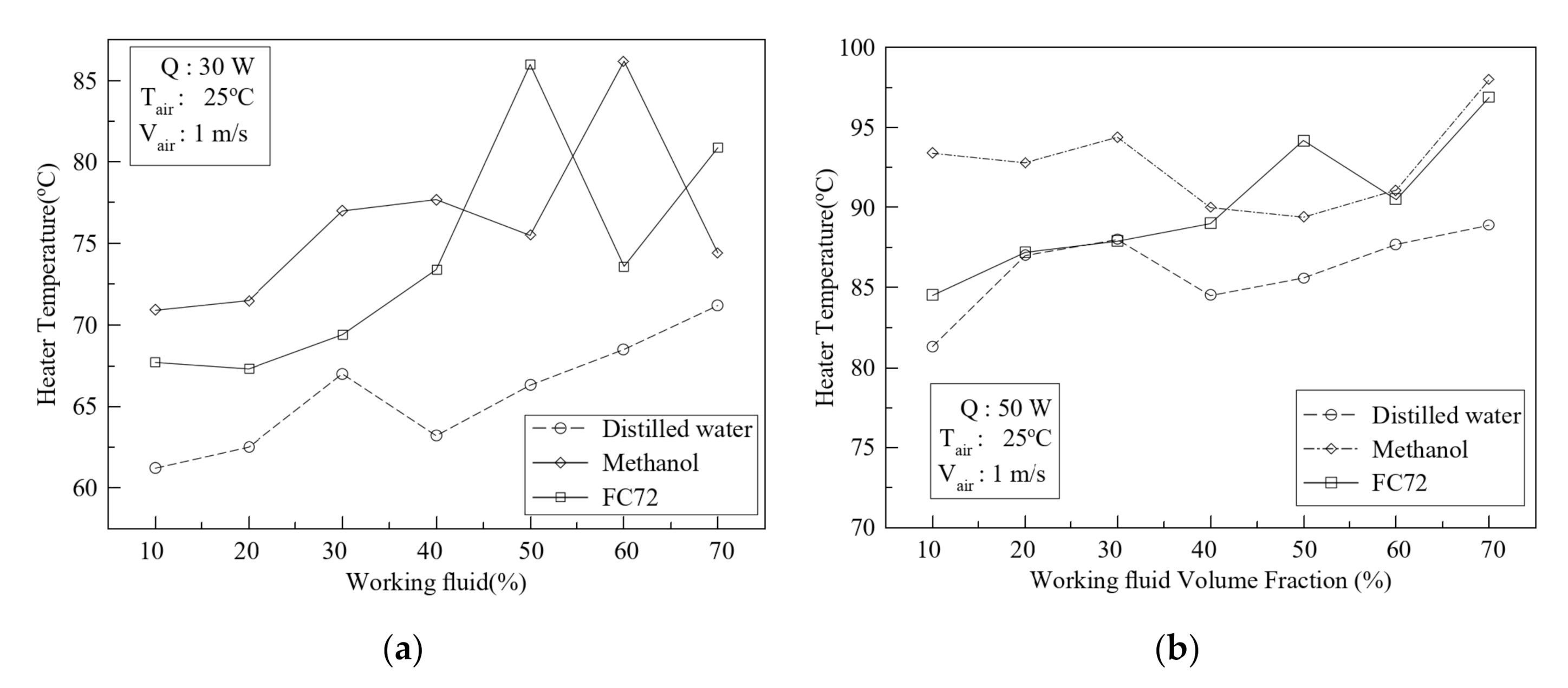
Figure 5a,b shows the effects of filling ratio on the heater surface temperature. As shown in
Figure 5, in the low filling ratio, heater temperature was kept at a lower state than in the high filling ratio. Usually, a conventional heat pipe requires the optimum charged ratio from 30% to 50% range [
1,
2,
3,
4], but in the current AHPHS, the increasing charged rate leads to performance deterioration. The AHPHS with VF = 10% water shows the best heat transfer performance. At 30 W heat inputs, performance difference depending on the charged ratio was larger than 50 W heat input. The temperature of each thermocouple position is an average of three temperatures installed in the same line in the axial direction. The results show possible working motion inside the AHPHS. It can be seen that as the heating amount increases, the temperature gradient at both sides also increases.
A physical reason for the variation in the heat transfer performance as a result of changing the charged rate of working fluid in the AHPHS can be described as follows. In the case of a low charged rate (10–20%), the inner working fluid has a short heat absorption time, and the heat can move easily to the condensing surface. In the case of 10–20% filling ratio by volume of the annular gap, the liquid working fluid is always placed at the lower regional part of the annular space of the AHPHS. It could act like the conventional symmetrical wickless heat pipe. However, in the case of large filling ratio, it is expected that the working fluid cannot circulate easily because the pressure difference between the evaporator and the condenser is not high enough, and the heavy weight of the working fluid can disturb the upwards movement of liquid.
4.2. Effect of Flow Velocity (Vair)
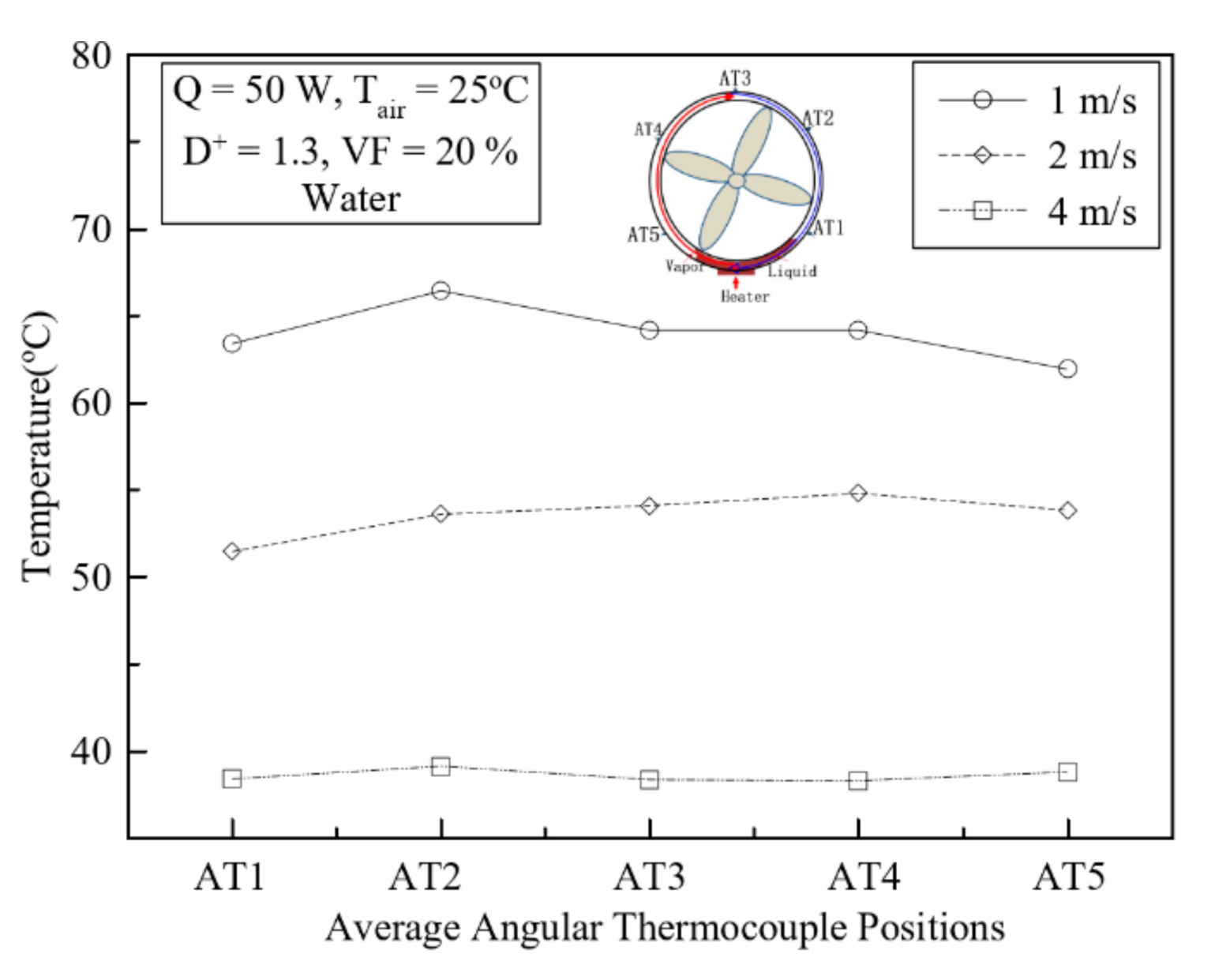
As shown in
Figure 6, the effect of flow velocity of cooling mediums on heat transfer rate of the AHPHS is serious in terms of temperature profile; this can be a typical trend for heat transfer phenomena.
Figure 6 shows large temperature difference depending on flow velocity. In the current AHPHS, it was found that when the air flow speed increased, the heat transfer performance increased. In the current AHPHS design, the cooling area can be the inner flow passage and outer flow surface. The present study shows the effect of flow speed affecting the inner cooling surface. Moreover, increasing flow speed results in increased flow rate. When the mass flow rate of the cooling air increased, the heat transfer rate obviously increased in every cooling situation of the conventional heat pipe. However, in the new design for electronics cooling, the AHPHS with large cooling area directly affected the internal liquid circulation. The condensing area affected the evaporation and internal condensation process because the adiabatic section does not exist in the current AHPHS.
The relationship between the air flow rate and heat transfer performance was investigated in the current experimental study. The flow speed was similar to the oscillatory behavior of a closed loop pulsating heat pipe. As shown in
Figure 6, at a low speed of 1 m/s, the temperature profile along the outer perimetrical surface showed that the inner working fluid had a circulatory motion. However, at a high flow speed of 4 m/s, a flattened temperature profile was observed, meaning that the inner working fluid circulated with a recirculating flow in the near center of the top section as shown in
Figure 1c.
4.3. Effect of Different Supplied Heat (Q) with Different VFs
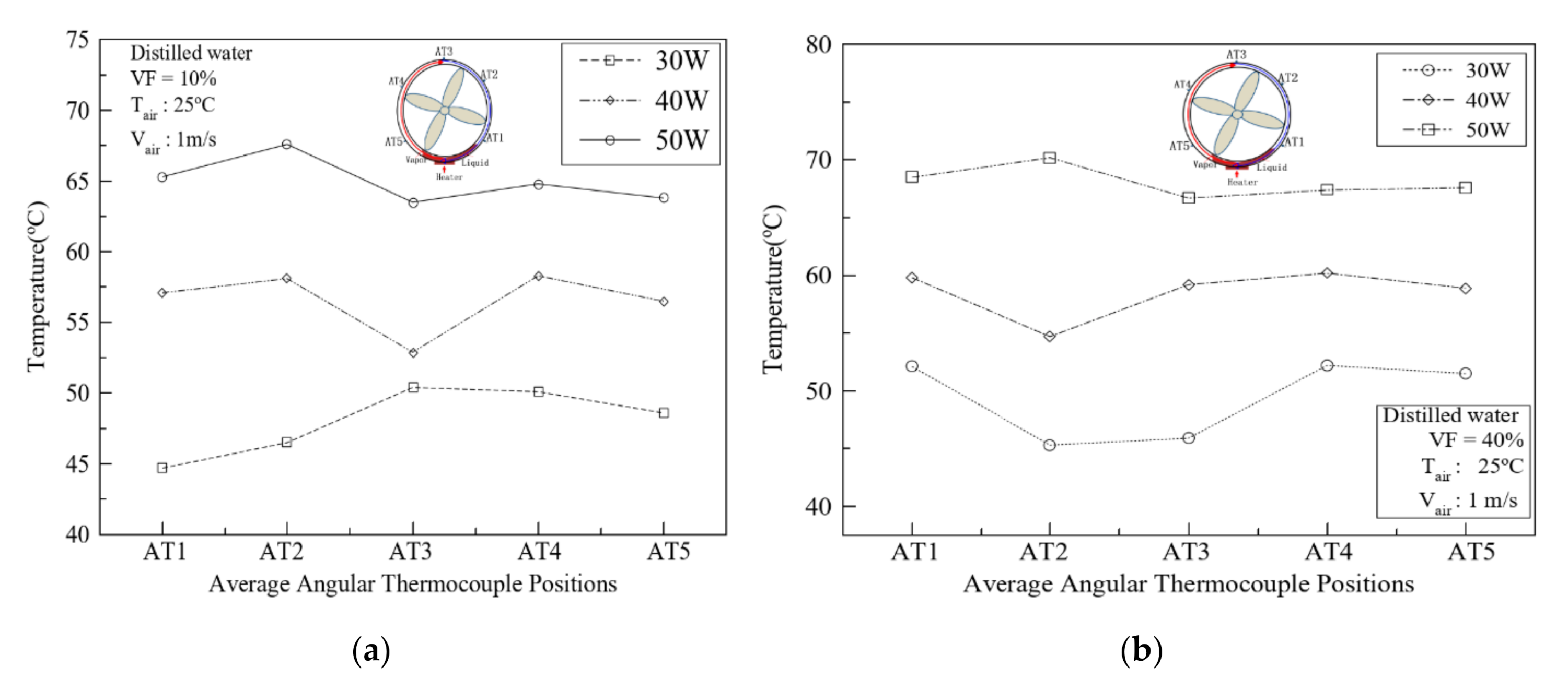
Figure 7a,b shows heat transfer performance with varying filling ratios. As shown in
Figure 7, unlike conventional heat pipes, at a low filling ratio of 10% (
Figure 7a), the temperature of the evaporator’s bottom surface shows the lowest value. It was expected that the working structure of the AHPHS was regular recirculating motion like conventional heat pipes. At a low filling ratio, the inner working fluid moved to the top position and returned to the bottom without circulating behavior. At a certain charged rate, the working fluid circulating motion was observed with temperature fluctuation. This means that the flow shows three-dimensional movement in axial or radial directions simultaneously. The optimum temperature appears when 10% distilled water is charged. However, the system with distilled water generates noise and vibration due to the startup characteristics, and the greater the heat applied, the more severely deteriorated the operation.
4.4. Effect of Temperature Difference between the Bottom and Top
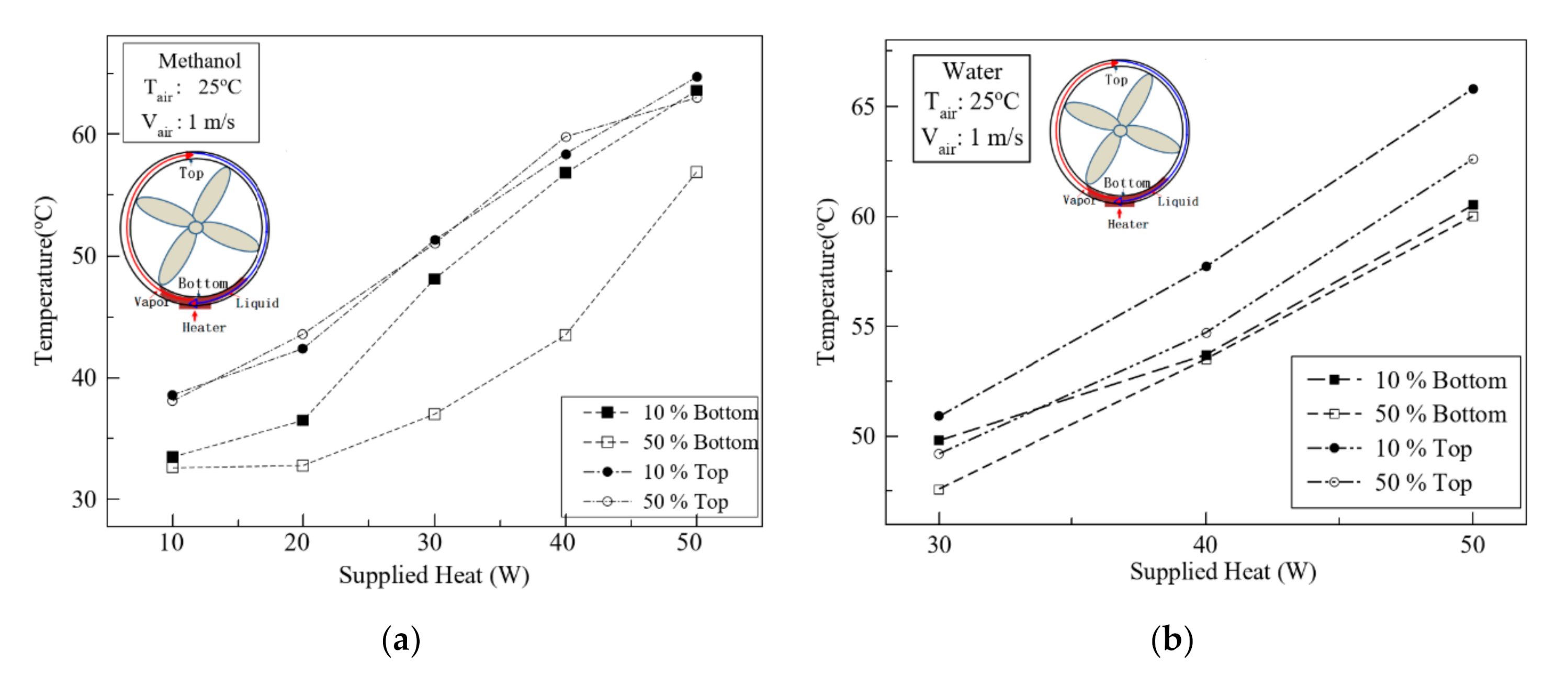
Figure 8a,b shows the temperature difference between the upper and lower surface of the central flow passage of the AHPHS (Mode 1) used in this study. As seen in
Figure 8a, when using methanol as a working fluid with filling rates of 10% and 50%, a large temperature difference between the top surface and bottom surface was observed. It was observed that the case of VF = 10% shows higher temperature difference than the case of 50% charging ratio. As shown in
Figure 8b, with water, the temperature difference between the bottom and top surface was reduced. The 50% charged case showed lower temperature difference than methanol. In other words, water can circulate through the annular space from the evaporator to the condenser. As a result, the internal condensation process works not only at the top but also at the bottom. Depending on the condensing area size, the cooling performance can be somewhat varied. Therefore, it was also shown that when VF of the internal working fluid is low, condensation may be caused at the top or at the bottom at a certain heat dissipation rate.
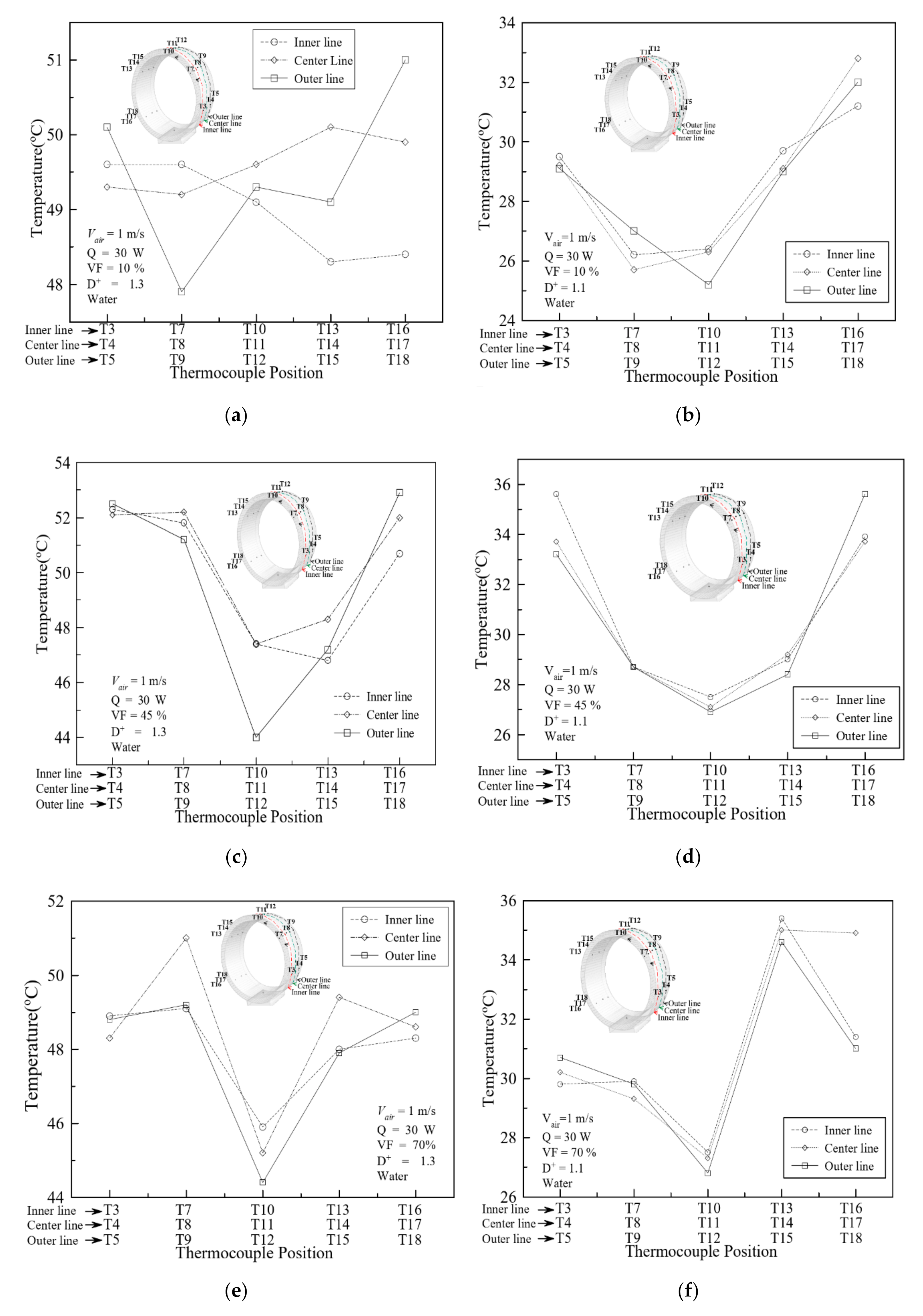
4.5. Effect of Three-Dimensional Temperature Profile
As shown in
Figure 9a–f, temperature profiles of the outer surface shown in
Figure 3 (50 mm length and 12.5 mm interval) along the circumstantial position of the AHPHS presented different filling ratios. In the case of VF = 10%, as in
Figure 9a with
D+ = 1.3, temperature profiles with different circumstantial positions do not show a certain trend. This can be expected that the working fluid can move and circulate in three-dimensional directions unlike the case of
D+ = 1.1 (
Figure 9b) which expected to be working in circular motion. Three-dimensional flow can be combined with axial, circumstantial, or any angular movements. This means that working fluid inside the AHPHS with low VF acts like Type A and Type B circulation simultaneously, as shown in
Figure 2b. With
D+ = 1.1 (
Figure 9b), however, circulatory vapor flow can be expected. In the case of VF = 45% (
Figure 9c,d), although the temperature profile has a similar trend, different temperature changes in the circumstantial position of
D+ = 1.3. It can be expected to show the circulating vapor flow. This means that inner annular space is occupied with a sufficient amount of working fluid, and the flow motion is dominated by a circumstantial direction, like Type A in
Figure 2b. When diameter ratio
(D+) was 1.1, the temperature profile did not vary significantly in the axial direction. It was expected that the vapor flowed in a circulatory manner like Type A. In the case of VF = 70% (
Figure 9e,f), the internal working behavior is unexpected. As shown in
Figure 9e,f, vapor flow in the AHPHS with a large filling ratio is limited in the upper space, and the heat transfer by vapor circulation is deficient. It was also observed that a small annular gap space restricted vapor flow, and axial temperature did not vary significantly.
4.6. Effect of Different Flow Passages
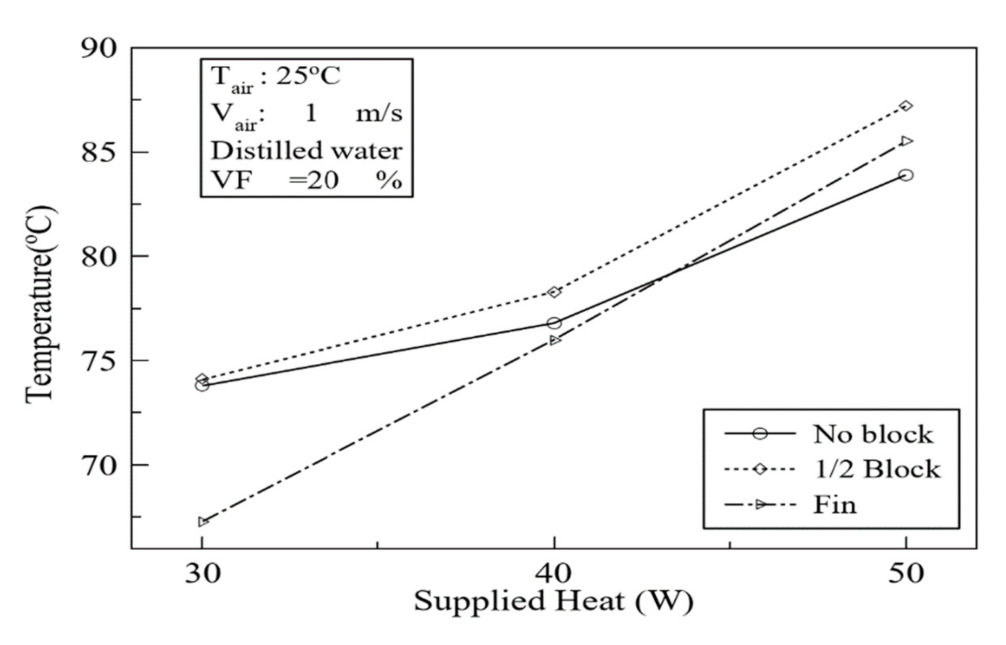
As shown in
Figure 10, the effect of central flow passage structures shown in
Figure 4a–c was studied. Central inner flow passage directly influenced thermal performance and temperature distribution parameters. Three central flow passages were tested—bare circular passage (Model A,
Figure 4a), half blocked (Model B,
Figure 4b), and finned (Model C,
Figure 4c)—to investigate system behavior depending on flow passage structure. The half-blocked model Model A showed higher heater surface temperature than other modes. It was expected that the finned case with a large heat transfer area would show increased performance, but the heater temperature at 30–40 W is lower than the case of 50 W, and large improvement was not observed.
Figure 10 shows the effect of flow passage area with different structures. As shown in
Figure 3, the flow area was half blocked to reduce flow passage into the focused condenser section. In the case of
Q = 30 W with VF = 20%, the temperature profile was compared, as can be seen in
Figure 10. As shown in
Figure 10, finned passage showed low temperature at 30 W, but increasing
Q lead to a rise in temperature. Therefore, in the current annular heat pipe, a large condensing area does not directly improve the heat transfer performance.
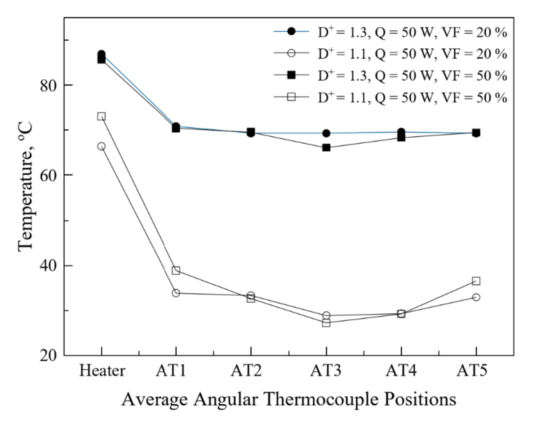
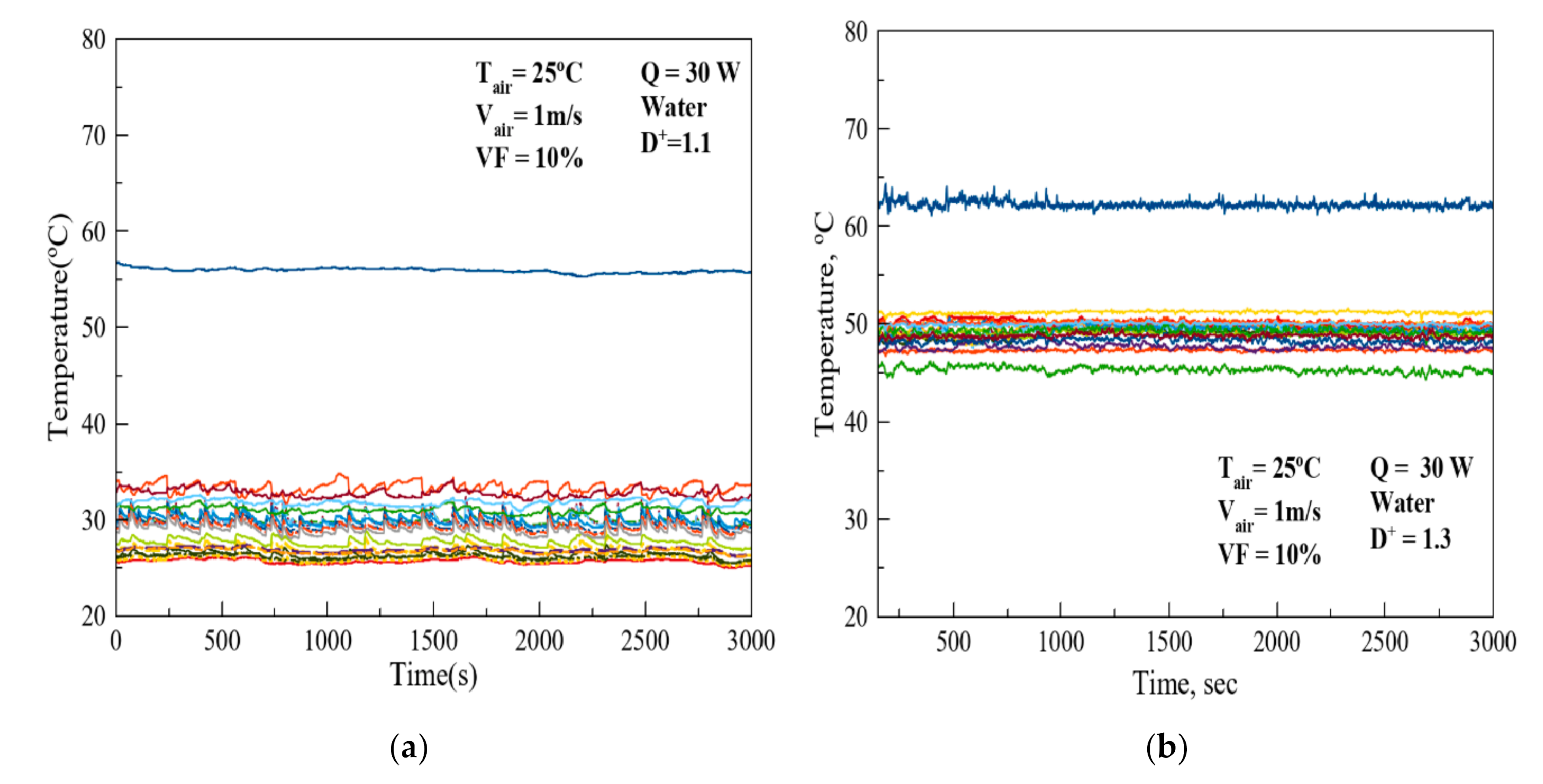
4.7. Effect of Diameter Ratio (D+)
The diameter ratio affected temperature profile and thermal behavior inside the AHPHS, as can be seen in
Figure 9. As shown in
Figure 11, an AHPHS with a different diameter ratio of
D+ = 1.1 was investigated to seek the effect of the diameter ratio (
D+). As reported in Ref. [
10], increasing diameter ratio was expected to increase thermal performance, but within the current experimental work, the thermal performance was increased with the decrease of diameter ratio. As shown in
Figure 11, heater temperature in the case of
D+ = 1.1 clearly shows lower values than the case of
D+ = 1.3. Decreasing diameter ratio means reducing annular space. The AHPHS with reduced space shows much active temperature variation, and this is expected due to the active flow behavior of working fluid. This effect is shown in
Figure 12. The temperature profile with
D+ = 1.3 is far above the case of
D+ = 1.1. As shown in
Figure 13, temperature fluctuation with
D+ = 1.1 is slightly above
D+ = 1.3, but the temperature of every thermocouple was kept at a low value.
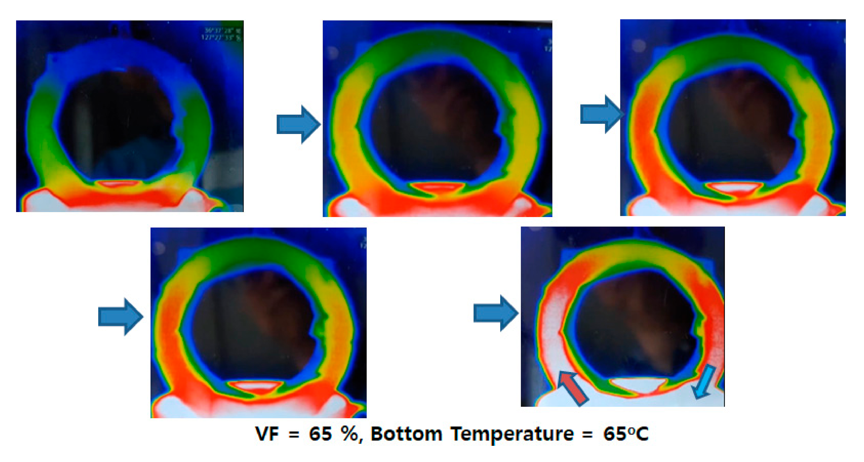
As shown in
Figure 14, the AHPHS shows the right circulation behavior, flowing with circulated motion. In
Figure 14, the thermal contour image of the front annular end was observed by an infrared thermal imaging camera. The thermal image shows the moving state of working fluid from the heat input to liquid circulation. In the evaporator, the absorbed heat makes vapor, and therefore the vapor moves steadily to the top condenser section.
5. Conclusions
An experimental study was carried out to verify continuous operation and thermal behavior of an AHPHS. The present study showed that the current AHPHS system has uneven working characteristics.
The present AHPHS shows special 3D working behavior with a low charged ratio of working fluid unlike conventional heat pipes. The charged ratio of the working fluid and pipe diameter ratio were sensitive parameters that affected the performance. In the present system with D+ = 1.1 and 1.3, reducing diameter ratio leads to improved thermal performance and active fluid motion.
The optimum charged filling ratio differed depending on the diameter ratio. For D+ = 1.3, optimum VF was 10–20%. For D+ = 1.1, optimum VF was 20–40%. Filling ratio was very sensitive to the angular temperature profile.
The block for maximizing the effect of the condensing point was insignificant, but it was confirmed that the condensing point was not only present at one point but also in the lower point when the fluid volume was small. In addition, at 30 W, the AHPHS with finned flow passage showed low temperature, but increasing Q lead to a rise in temperature. This means that the current large condensing area does not directly improve the heat transfer performance.
The axial and angular temperature distribution was also affected by the filling ratio and diameter ratios. The AHPHS with low filling ratio and axial and angular temperatures showed a three-dimensional distribution which can be induced by dynamic vapor motion. In the present works, AHPHS with D+ = 1.1 and VF = 10–20% expected showing the optimum thermal behavior.
Research activity on annular heat pipes is rare due to the difficulties of using inner space as a heat transfer area. In this paper, the possible applications of an annular configuration are proposed.


