Article

Integration of a Heuristic Multi-Agent Protection System into a Distribution Network Interconnected with Distributed Energy Resources

College of Engineering & Science, Victoria University, Melbourne, VIC 3011, Australia
*
Author to whom correspondence should be addressed.
Energies 2020, 13(20), 5250; https://doi.org/10.3390/en13205250
Submission received: 2 September 2020 / Revised: 5 October 2020 / Accepted: 7 October 2020 / Published: 9 October 2020
(This article belongs to the Section F: Electrical Engineering)

Abstract

:
In conventional method protection schemes are devised for certain operation conditions with fixed settings throughout their operation life, however, protection systems in interconnected distribution networks rely on a detailed analysis of fault current contribution and variation in operation conditions under real-world scenarios. In fact, the concept of Adaptive Protection System (APS) and possibility of the adjustment for protection settings within modern Intelligent Electronic Devices (IEDs) have introduced desired functionalities for protection systems to cope with complex operation scenarios envisioned within future power system networks. In this paper, a novel protection system based on Multi-Agent System (MAS) and heuristic decision-making is proposed to update protection settings of the protection IEDs with respect to prevailing operation conditions in an interconnected distribution network. The adopted methodology is reliant on real-time simulation of a distribution network interconnected with Doubly-fed Induction Generator (DFIG) wind farms where different fault scenarios are applied to evaluate the functionality and performance of the proposed Multi-Agent Protection System (MAPS). In addition to that, combination of knowledge sharing between different protection IEDs and logic reasoning are integrated to fulfill protection task under real-world operation scenarios. The significance of the proposed MAPS is the improvement in protection system of the interconnected distribution network.

1. Introduction

Generally, the interconnection of distributed energy resources (DERs) such as DFIG wind turbines, photovoltaic (PV) panels, diesel generators (DG) and battery storages (BS) into distribution networks is considered a promising solution for supplying cheaper and cleaner electric power to customers. However, the complexities introduced into the protection systems and functioning of protective relays within interconnected distribution networks impose technical challenges to the reliability and efficiency of the distribution system operation. In fact, with the connection of DERs into a distribution network the assumption of unidirectional power flow does not hold as multiple generation sources contribute to supply electrical power under different operation conditions [1,2]. Thus, conventional system protection schemes in radial distribution networks such as time over current (TOC) curves with fixed decision boundaries are not reliable to meet the desired reliability and performance requirements for the protection systems within interconnected distribution networks. Many years of practice in developing protection schemes based on conventional protection system strategies and introduction of modern information and communication technologies (ICT) infrastructure embedded into power system operation have provided opportunities for power protection engineers to adopt various protection strategies for reliable and safe interconnection of DERs into distribution networks. In the literature [3,4,5], different protection methods have been proposed to address protection complexities corresponded to interconnection of DERs into distribution network. In its simplest form fault current limiters (FCLs) have been proposed to protect power system component against excessive high currents contributed by DERs connected into distribution networks. This approach has mainly been adopted to prevent undesired thermal stresses and avoid exceeding fault current capacities for circuit breakers (CBs). In [6] Gokhan et al. investigated the effect of FCLs in different locations to reduce the fault current contribution from an interconnected wind farm in a range of CB ratings within the distribution network. By adopting a similar approach, Sharhriari et al. [3] proposed solid state FCL (SSFCL) constituting parallel connections of an inductor, GTO thyristor and metal oxide variostor (MOV) to address coordination between TOC protection curves and fuses within a radial distribution network interconnected with DERs. The proposed SSFCL is used at the connection point of each DER where the inductor is devised to prevent high fault current and the MOV suppress overvoltages while the GTO thyristor is the low resistance path during normal operation conditions of the distribution network. Further improvement for protection system based on FCL have been addressed by Bayati et al. [7], where application of FCL with optimization in DER placements have been considered to improve operation time for the protection relays and increase reliability within interconnected distribution networks. In spite of the low cost and reduced complexities when using FCL methods for protection systems in interconnected distribution networks, it is mainly only effective for specific radial distribution networks with low DER penetrations.
In recent years with the introduction of modern numerical relays known as IEDs for power the concept of adaptive protection systems (APS) have been studied and investigated in many research papers [8,9,10,11,12] to address protection challenges in interconnected distribution networks. In its general form APS is devised based on online activity that modifies protection settings for preferred protective response of the protection system to a change in power system condition which is usually automatic. In early applications of APS Rockefeller et al. [13] proposed a centralized architecture utilizing computational and data storage devices to underscore feasibility of better performance for protection system by adjustment to protection settings in protection IEDs. Further, to that Rockefeller et al. introduced APS for improvements in protection systems at the substation level as variations in operation conditions and topological changes take place. Additionally, application of the APS for adaptive distance protection has been discussed for improvement of the relay performance within multi-terminal transmission lines [8]. In [9] Brahma et al., adopted APS to address coordination problems within a distribution network where fault current contributions from DERs can affect selectivity and performance of the protection system. The outline of the proposed protection scheme is based on dividing the distribution network into separated protection zones and applying online adjustment for differential protection function according to the operation condition in each protection zone. For protection systems in microgrids Oudalove et al. [10] proposed APS to address protection issues related to variations of the fault currents during grid-connected and islanding mode operation. Utilizing modern ICT and protection IEDs Oudalov et al. adopted a “connect and forget” approach in which a centralized architecture for the protection system is devised to automatically adjust the protection settings for TOC curves protection functions depending on the grid-connected or islanded mode operation conditions. Finally, Vasileios et al. [14] designed and implemented APS for interconnected distribution network in which a non-linear programming (NLP) method such as particle swarm optimization (PSO) is used to adjust the protection settings of the overcurrent protection functions to improve coordination between protection IEDs. Having discussed the advantages for centralized architectures for APS, there have been few research papers which have embarked on the study of decentralized APS and its reliability for protection systems in interconnected distribution networks. In designing a decentralized APS Maleki et al. [15] proposed a scale down for the centralized architecture into individual protection IEDs where each IED constitutes a central unit for monitoring and adjustment of the protection settings according to changes in topology and operation mode of the DERs connected to the network. Bahadornejad et al. [16] also proposed a decentralized approach based on estimation of the Thevenin equivalent network upstream and downstream of the DERs’ location where a fault current calculation method is used to adjust the protection settings for the CBs upstream and downstream of DERs. In conclusion, adaptive protection systems are flexible and capable to be utilized for complicated protection systems within interconnected distribution networks; however, given the tightly coupled interactions between protection IEDs the application of APS is developed for specific distribution networks and in large scale interconnected distribution networks the complexities increase.
Another important advancement in developing protection system is associated to the MAS concept, where a combination of ICT and computer science techniques is employed to deal with large-scale, heterogeneous and interdependent problems within protection systems of the interconnected distribution networks [17]. In fact, the idea of knowledge sharing and communication between protection IEDs within a MAS framework have been an enabling factor to extend the conventional protection philosophy from the component level to the system level where total stability and avoiding cascaded failure are given high priority [18]. In the literature [19,20,21] various parameters such as architectural arrangements, agent types and agent interactions have been highlighted as important factors to develop a reliable and functional protection system based on MAS. For many protection systems based on MAS hierarchical architectures and layer-based arrangements of the agents have been proposed to fulfill protection tasks within power system networks [18,21,22,23]. Ming et al. [22] proposed a three layers hierarchical architecture for wide area protection applications in which not only an agent can have a local view of the power system but agents in various layers can fulfill wide area protection tasks by utilizing cooperation and behavioral interactions inherent to the agent technology paradigm. Although compared to the APS approach decision making in multi-agent-based protection systems is based on local and global information which is achieved through loosely coupled interactions between different agents but with the hierarchical layered-base architectures communication bandwidth and disruption of the communication link can be a main drawback to the performance of the protection system. In this paper a distributed decision making based on MAS and heuristic reasoning have been proposed to adjust protection settings with respect to dynamical changes in the operation conditions of distribution networks interconnected with DERs.
The structure of this paper is explained as follows: In Section 2, a typical distribution network interconnected with DERs is described to address protection challenges under various operating conditions and topological changes considering real-world operation scenarios. Later in Section 3, the proposed methodology for establishment and integration of heuristic MAPS are explained where different agent types and their interaction within the system protection are highlighted. In the implementation phase, real-time simulation studies on the performance of the MAPS are developed in Section 4 where simulation techniques such as hardware-in-the-loop (HIL) and co-simulation are adopted. Simulation results and verification of the MAPS functionalities for various operation scenarios are represented and compared with conventional TOC protection systems. Finally, conclusions are made based on the simulation results which highlight the advantages and significance of the proposed MAPS in dealing with system protection challenges arising due to the connection of DERs.

2. Problem Statement

Typically, in the planning and development of conventional distribution networks, specific operation conditions are determined as normal loading conditions with all other technical aspects related to control and protection systems including size, type and protection settings being gauged for duration of life cycle. In this paper, the core of the study is concerned with the protection system and conflicting operation conditions that prevail upon interconnecting DERs into distribution networks. Technically, conventional protection schemes are well-established and practiced based on fixed decision-making boundaries and local measurement variables such as current, voltage and power flow direction are continuously monitored to decide on fault occurrences within the designated protection zones. Although the aforementioned protection strategy is appropriate with radial distribution networks where single generation source supplies unidirectional power flow from network upstream to downstream consumers, interconnection of DERs at the distribution level can alter the unidirectional power flow paradigm as load-generation balance varies depending on the DER operation scenario. Therefore, with the prevailing changes in operating conditions of the interconnected distribution network, normal loading currents can vary introducing adverse effects in the reliability and dependability of the protection systems. As a matter of fact, system protection in interconnected distribution networks has become a hot topic for many research studies in the field of power system protection engineering where the prospect of future power grids is envisaged with connection to various types of DERs [24,25,26].
In the following, some of the challenges corresponding to system protection with various parameters and operating characteristics have been investigated to represent real-world operation scenarios within interconnected distribution networks. As the first step a typical distribution network interconnected with DERs is described.

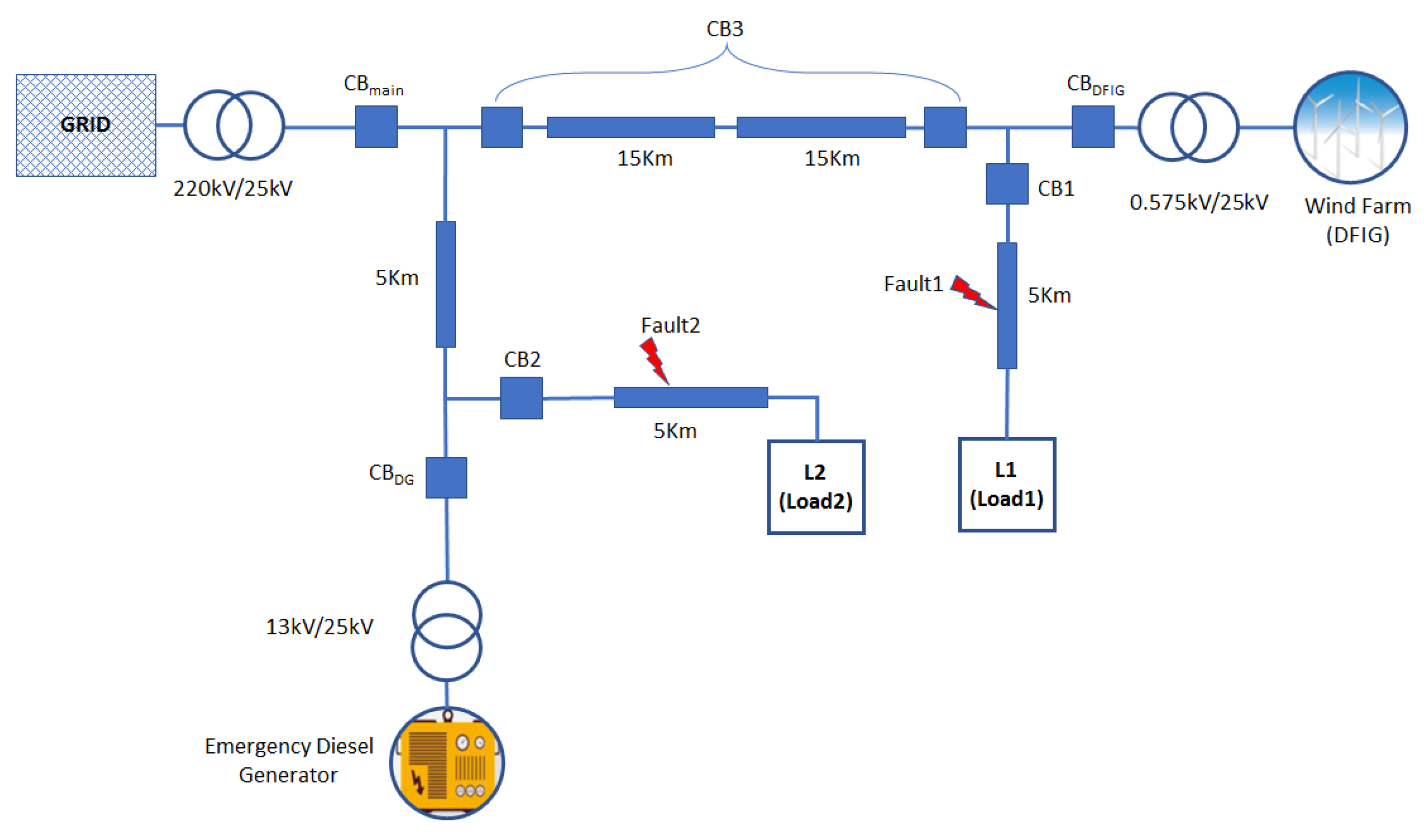
2.1. System Description

For the purpose of analysis and investigation of the system protection during any fault incident, modeling and simulation of the interconnected system plays a crucial role in evaluating the functionality and performance of the protection system. Therefore, to address a real-world scenario in the operation of an interconnected distribution network, a distribution network interconnected with DERs such as DFIG wind turbines and DG has been developed. Figure 1 shows a single line diagram for a distribution network which is connected to the grid through CBmain. The local power generation units at the distribution level consist of a wind farm with DFIG type wind turbines and DG which acts as frequency controller to distribution system during the islanded mode operation when CBmain is open. Also, Load1 (L1) and Load2 (L2) represent local loads supplied by both grid and local generation sources (DFIG and DG). In addition to that, the sizing and capacity of the local generation sources have been selected to be able to supply the local loads (L1 and L2) during islanding operating mode which is a desirable characteristic to form an islanded distribution system. The CBs illustrated in Figure 1 have been devised to operate and isolate faulty section(s) of the distribution lines with trip signals which are sent by protection IEDs associated to each CB. It is also worth mentioning that there are two fault scenarios, Fault1 and Fault2, shown in Figure 1, which are considered to evaluate the system protection performance against conventional approaches. Finally, CB1, CB2, CBmain and CBDFIG are configured to operate with TOC protection function while CB3 (shown in Figure 1 as a pair of CBs) is considered to operate on a differential protection function.

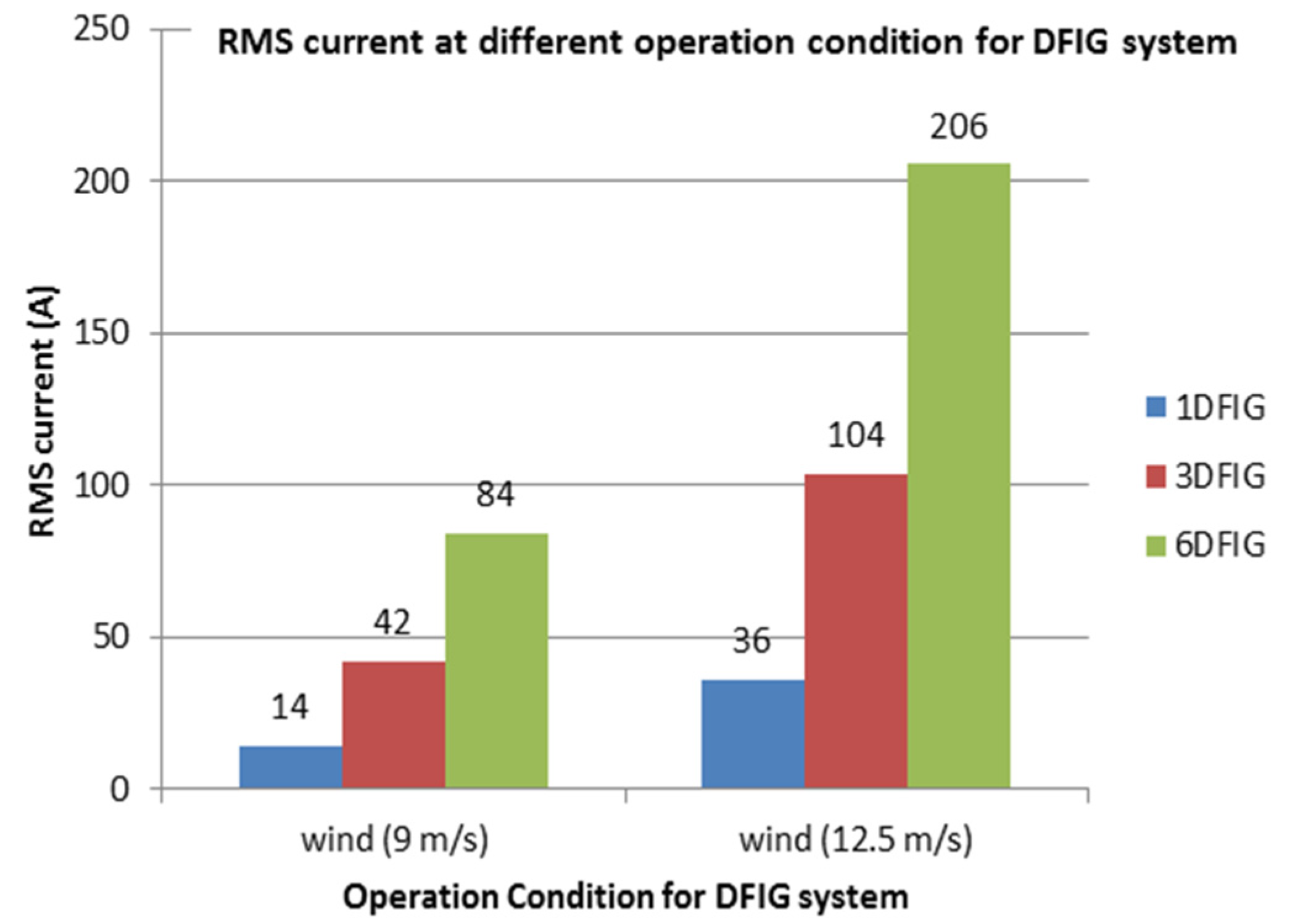
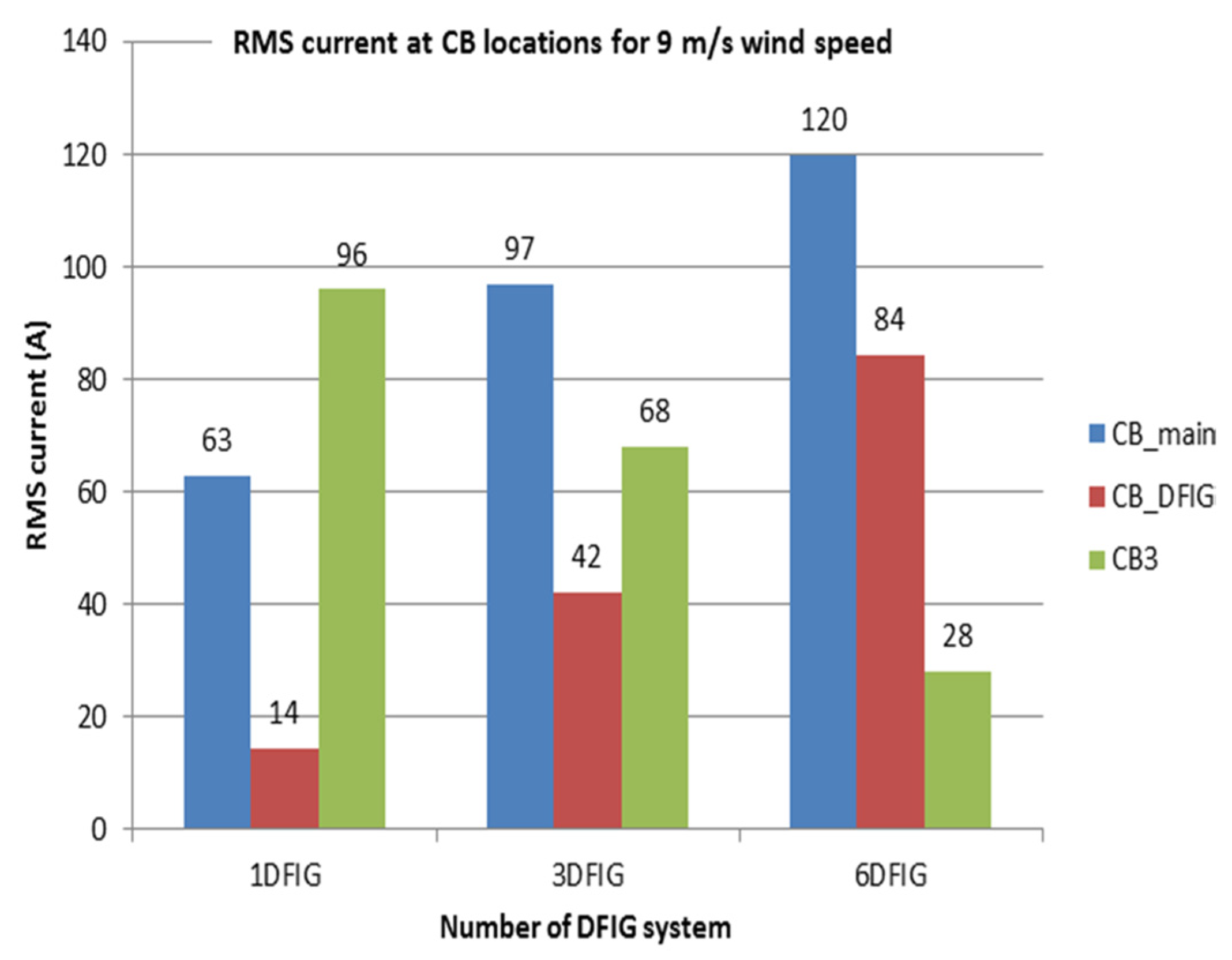
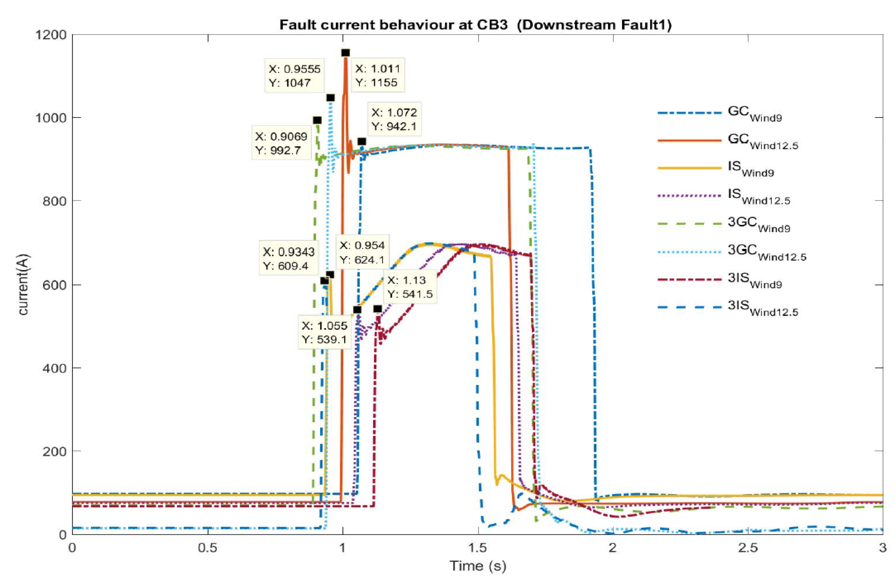
2.2. Operation Scenarios

In relation to connecting DERs such as DFIG systems into distribution networks, there are operational aspects corresponding to embedded control strategies and sizing of the DFIG systems which can introduce technical complexities in devising protection settings. As a matter of fact, variations in wind speed over a wind farm area can affect the power output from DFIG wind turbines altering the load-generation balance by causing changes in the operating conditions at each CB location. Thus, with respect to conventional approaches, the protection settings for TOC curves have to be adjusted accordingly to ensure reliable and safe operation of the interconnected distribution network. In order to highlight variations in operation conditions at different CB locations within a interconnected distribution network, Figure 2 and Figure 3 represent normal loading currents for different wind speed and size of the DFIG wind turbines, respectively. Figure 2 represents the root mean square (RMS) currents at the point of common coupling (PCC) connection of the DFIG system (CBDFIG) which can vary depending on the available wind speed and the number of connected DFIG systems in the wind farm.
Similarly, Figure 3 illustrates variations in loading currents at different CB locations as the number of connected DFIG systems at the PCC changes. Consequently, having represented the effective parameters in variations of load currents within the interconnected distribution network, it is obvious that adjustment for protection settings is imperative to maintain the desired reliability and performance of the protection system.

2.3. Grid Connected/Islanded Mode

One of the important operation characteristics for an interconnected distribution network compared to radial distribution networks is the ability to operate in islanded mode where the distribution system relies only on local DER units to supply electric power for consumer loads. Although the possibility to operate under islanding conditions can introduce improved power quality for customers at the distribution level, there are technical issues corresponding to system protection which are critical and need to be addressed. Basically, unlike grid connected mode, fault current levels under islanded mode are altered due to the limited electric power capacity of the DERs for supplying a sustained fault current during the fault occurrence period. Moreover, with respect to low mass inertia within the islanded part of the distribution network, the fault current characteristics can vary and a detailed time-domain simulation for analysis of transient short circuit current is necessary. Therefore, in order to investigate the effect of transitioning to islanded mode on fault current behavior, a 3-phase fault scenario downstream of the DFIG wind farm at Fault1 location has been applied for both grid-connected and islanded mode. As illustrated in Figure 4, fault currents under grid-connected operation mode are much higher compared to islanded mode as the operating condition of the DFIG system such as wind speed and number of connected DFIG system are negligible. Moreover, comparing the time-domain response and transient envelope of the fault current within islanded mode they are different as the maximum fault current occur multiple cycles further from the fault initiation time. The labels GC and IS represent grid-connected and islanded mode of the operation for interconnected distribution network while the subscripts point to the operation conditions for the DFIG system indicated by wind speeds. For example GCwind9 represents grid-connected mode in which the operation condition of the DFIG system is for a wind speed of 9 m/s. In a similar way the IS represents the islanded mode operation where the operation condition of the DFIG is for a wind speed of 9 m/s (ISwind9). Also the prefix number to the labels represents the number of DFIG systems connected to the grid and 3GCwind 12.5 represents the operation conditions of the interconnected distribution network under grid-connected (GC) mode when 3DFIG systems are operating and the wind speed is 12.5 m/s.
It is obvious from Figure 4 that under different operation mode, the requirement for the adjustment of the protection settings within the protection IEDs is inevitable. Also, to further investigate the time domain performance of a TOC curve devised for conventional system protection, comparisons have been made for fault currents at CB1 and CB2 under different modes of operation to highlight the protection complexities within an interconnected distribution network. As seen in Figure 5, the time domain responses of the fault currents during islanded operation mode are not detected by the TOC curve as the fault current level and fault current duration are not sustained for the minimum time required to trigger a trip for the corresponded protection IEDs. Therefore, it is essential for system protection that the TOC curve settings be adjusted according to the operation mode of the interconnected distribution network. In Figure 5 the notation for GCsubscript follows the same notation as explained for Figure 4, however the prefixed number and fault suffix correspondingly represent the number of DFIGs connected to the grid and the fault locations. For example 3GCwind9 Fault1 represents a fault current curve at CB3 when a 3-phase fault occurs at the Fault1 location and the number of DFIG systems connected to the grid is three. Also the International Electrotechnical Commission (IEC) curves highlight the TOC protection functions based on the fixed pickup current settings at CB3 locations with consideration of the DFIG operation conditions.

3. Proposed Methodology

Having discussed the complexities in determining protection settings for TOC curves in protection IEDs within interconnected distribution networks, system protection challenges based on conventional methods have been identified as inaccurate and unreliable to meet the desired performance for system protection. On the other hand, incorporation of modern ICT infrastructure has provided opportunities to apply sophisticated communication-based protection schemes which can overcome drawbacks related to conventional protection system as simple fixed decision boundaries are not reliant on the operating conditions within interconnected distribution networks [25,27]. Therefore, a distributed approach for system protection has been proposed where MAS has been integrated into the protection system to enhance cooperation between protection IEDs through messaging communications. Moreover, a decision-making process based on human expert knowledge and message passing between protection IEDs are established to decide on appropriate setting groups for TOC curves corresponding to the operating conditions of the power system. In the following subsection, various aspects related to the development and implementation of the proposed methodology are explained.

3.1. Multi-Agent Protection System (MAPS)

As explained earlier, by integrating MAS into a protection system, there are certain characteristics and features such as cooperative behavior, distributed architecture and scalability which highlight the desired flexibility to model large-scale interactive complex networks similar to protection schemes within interconnected distribution networks. As a matter of fact, in the proposed MAPS strategy, MAS constitutes the core of a decision-making process where protection tasks are fulfilled through different subtasks and in cooperation with other protection IEDs deployed within the interconnected distribution network. Thus, unlike the conventional approach, MAPS aims to support the functionalities of the system protection by considering wide area information to identify the prevailing changes within the power system network. This in turn introduces advantages for accurate and reliable decision-making processes to select appropriate protection group settings according to the operating condition of the interconnected distribution network. In order to illustrate the detailed interactions and cooperation between the elements within MAPS, Figure 6 represents a use case scenario where messaging communication and different agent types are shown. As shown in the figure, the real-time measurement data including current transformers (CT) and voltage transformers (VT) values are the inputs from the power system into the protection IED specified with a dashed line boundary. Measurement, communication and coordination agents deployed within the protection IEDs illustrate the cooperative behavior between each agent through messaging exchange. Also, the output from the MAPS architecture shown in Figure 6 is the protection group settings which are derived from the expert knowledge database based on heuristic reasoning defined in the next subsection.

Protection Agents

Aside from architectural arrangements and interactions explained for MAPS, to establish an operational/functioning framework for deployment of different agent types, a similar approach in software development life cycle (SDLC) has been adopted. The outcome of this stage is highlighted by analysis and design phase as conceptualization and implementation of agent’s behaviors and their tasks within MAPS are defined [28,29,30]. Moreover, in developing MAPS, certain specifications including agent development software and the Foundation for Intelligent Physical Agents (FIPA) standards have been considered to enhance scalability and interoperability within the proposed MAS framework. In the following paragraphs, details on agent types, responsibilities for each agent and their interaction protocols are explained.
• Measurement
The measurement agent is specified by MEASU agent type and its responsibility is to receive real-time measurement data and monitor the operating conditions at the location of each CB. In addition to that, a measurement agent can send messages for requesting coordination/adjustment for protection settings to a coordination agent. For development of the measurement agent a JAVA class has been defined in which structure data including CB name, type of component that the CB is protecting and measurement data variables such as current, power flow and voltage are assigned during the deployment phase.
• Communication
The communication agent belongs to the COMM agent which is a JAVA class developed to fulfil the task of knowledge sharing between neighboring protection IEDs by sending request messages and receiving back replied measurement data from the requested CBs. Furthermore, the information received from the neighboring protection IEDs are delivered to coordination agent for supporting decision-making process by incorporating additional information from system operating condition. For communication agent data structure are allocated to hold CB names of the neighboring protection IEDs.
• Coordination
The core of decision-making and incorporation of the heuristic rules for adjusting the protection settings in each protection IED is implemented in the coordination agent. In fact, the coordination agent demonstrates a distributed decision-making entity where measurement information are collected and taken into account for evaluation against the heuristic knowledge that forms the reasoning basis to select proper protection settings from the existing setting groups in protection IEDs. In order to be able to develop a fully automated protection system based on protection agents as defined above, an interaction protocol between different agent types has been devised which can autonomously and interactively engage each agent type to address system protection. In Figure 7, the unified modeling language (UML) sequence diagram for interaction between the protection agents is illustrated.

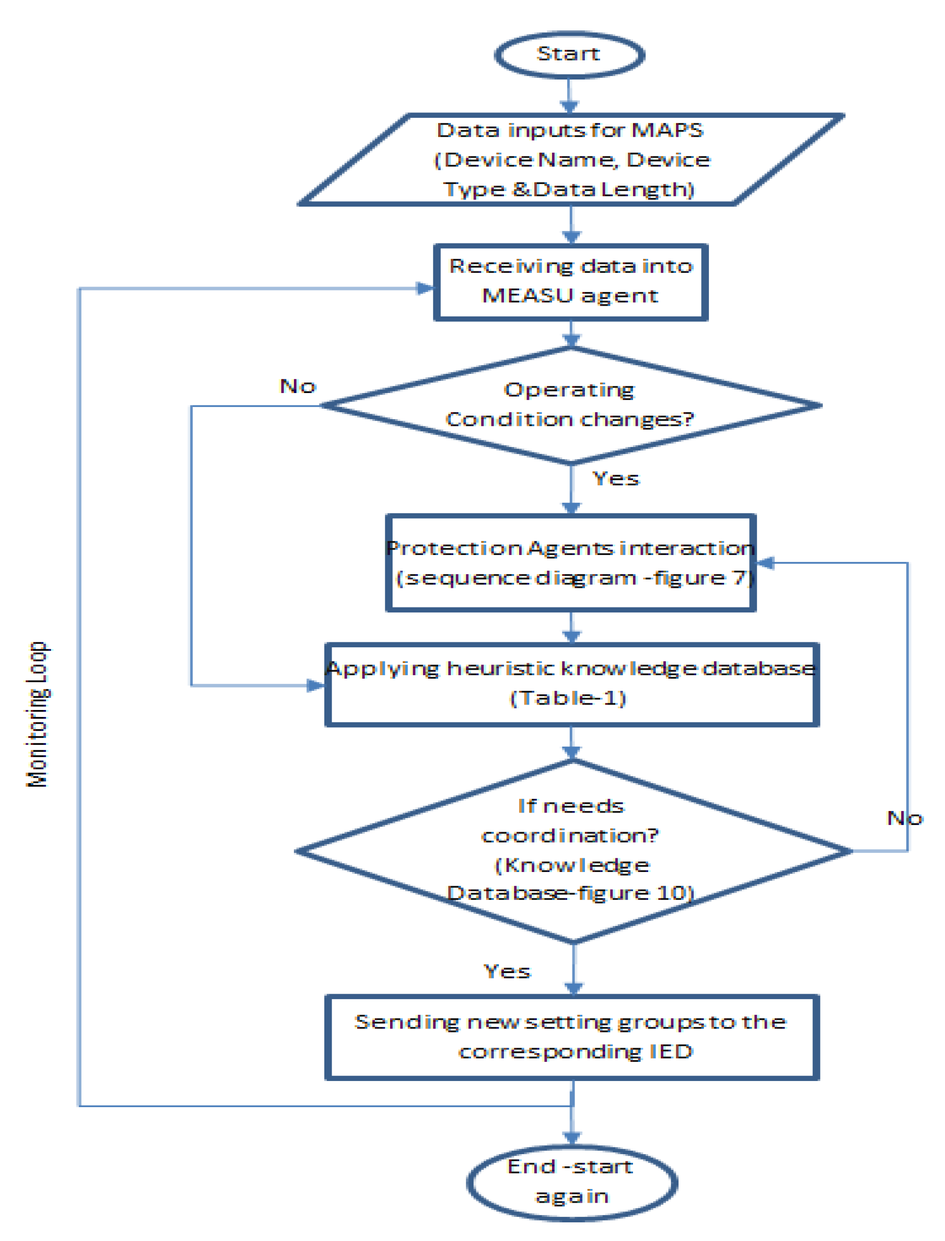
3.2. Heuristic Decision Making

In system protection, the decision-making process constitutes the core of protection schemes in which decisions are taken to isolate and disconnected faulty sections of the power system network in the case of abnormal operating conditions. Generally, for conventional approaches, deterministic algorithms are utilized in protection schemes where fixed decision boundaries are compared for locally measured criteria such as TOC curves, distance protection, differential protection functions, etc. [31]. Although development of the protection system based on deterministic decision-making has been effective within radial distribution networks, for interconnected distribution networks with protection complexities arising from inherent transitions in operating condition of the DERs adopting sophisticated decision-making strategies is inevitable. Thus, currently in the course of modern ICT infrastructure with potential enhancement for integrating protection schemes based on communication networks and data exchanges between protection IEDs, advanced decision-making procedures have been explored as appropriate solutions for complex interactive networks (CINs) such as interconnected distribution networks [26,32]. Thus, for the proposed MAPS, a heuristic approach has been incorporated into the decision-making process as the protection scheme is divided into sub-tasks relying on the MAS framework to consider respective information from neighboring nodes [33,34]. In comparison to deterministic approaches where objective knowledge such as formulas (fault current calculation methods) and theorems (unidirectional power flow paradigm) are utilized to produce a solution for decision boundaries, heuristic techniques are defined as rule of thumbs taking both objective and subjective knowledge (intermittencies in renewable energy resources and topological changes) to reduce the complexities of the problem at hand. Therefore, depending on the applications, the main advantage of integrating heuristics into the decision-making process for protection systems within interconnected distribution networks is to reflect the intuitive knowledge from an expert knowledge database about the solution for group settings in protection IEDs. In the following, two main factors in the proposed decision-making algorithm state transitions at various CB locations and expert knowledge database are explained.

3.2.1. State Transitions

Unlike radial distribution network, the steady state load-generation balance for interconnected distribution networks endures uncertainties arising from the availability of renewable energy resources and topological changes which introduce dynamic transitions into the normal operating conditions at each CB location. Therefore, in terms of addressing system protection reliability and selecting protection settings for TOC curves in the protection IEDs, investigating the state transitions within interconnected distribution network is imperative. Basically, for the proposed interconnected distribution network there are different parameters considered to identify transitioning states which include RMS current, active power and CB position at the grid-connection point. In addition to that, to further interrelate transition states with potential fault current levels at each CB location, neighboring protection IEDs are characterized by upstream/downstream nodes which provide explicit information regarding topological connections in the protected zone of the protection system. As illustrated in Figure 8, the state transition diagram for the proposed interconnected distribution network is represented by lines and circles showing distribution lines and CBs, respectively.
In Figure 8, while there are four different states for the operating conditions of the DFIG system discussed in Section 2, arrows representing power flow direction for states 3 and 4 have been illustrated for the sake of clarity and brevity of the lines. It is obvious from Figure 8 that with the change in wind speed from 9 m/s to 12.5 m/s variations in the RMS current, active power and power flow direction can occur through all CBs within the interconnected distribution network. Also, the dashed line circle in Figure 8 highlights the possibility of islanded mode operation as CBmain is removed from the state transition diagram. In fact, the advantages of identifying CBs with their operation states and connection links of neighboring protection nodes are considered the knowledge representation of the system which will be updated through the MAS architecture defined for the proposed MAPS. In the following, the process of representing system knowledge and applying the logic reasoning for decision making process within MAPS are discussed.

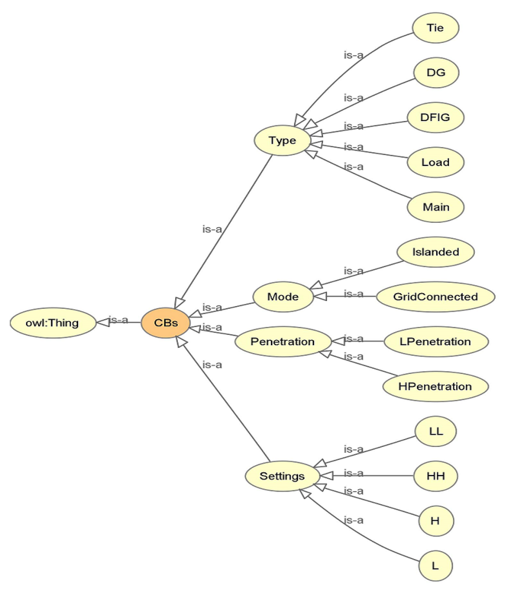
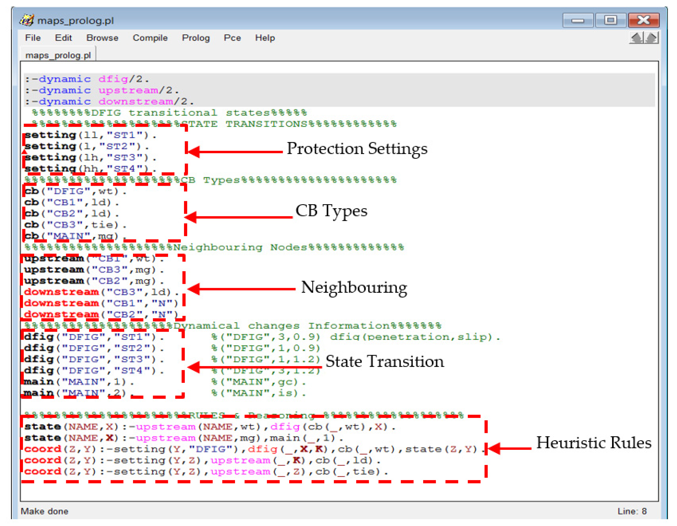
3.2.2. Knowledge Database Representation and Reasoning

As it has been addressed earlier, protection challenges within interconnected distribution networks are complicated and multifaceted problems [35,36] where applying conventional protection strategies cannot be reliable and sufficient enough to cover wide range of operation scenarios within this type of network. In addition to that, with the current trend in connecting DERs into distribution networks, requirements for adopting a scalable and expandable system protection strategy are becoming imperative to meet system reliability for heterogeneous, large-scale interconnected distribution networks. Thus, in this subsection a novel approach based on human mind decision-making is incorporated within the MAS framework in which system information is acquired from interactions between agents constituting a distributed architecture deployed throughout CB locations. As a matter of fact, the proposed decision-making process relies on two stages consisting of knowledge acquisition and logic reasoning which are wrapped into a coordination agent within MAPS to automate the process of selecting appropriate protection settings under various operating conditions. For interconnected distribution networks, there are certain parameters and properties which are characterized as relevant information in the process of decision-making in system protection. Hence, the ability to present this information as system knowledge is of particular importance to establish the proposed MAPS. Consequently, Table 1 lists system information such as CB types, state transitions and upstream/downstream nodes for each CB location which provides an informative system knowledge database to facilitate MAPS decision making process by assimilation of subjective elements involved in system protection within interconnected distribution networks. As it is seen in Table 1, various types of CBs have been introduced with different notations specifying power components that protected by each CB against any power system fault. For example, the types Wind Turbine (WT), Load (LD), Circuit Breaker (CB) and Microgrid (MG) represent wind turbine, load, general circuit breaker and main grid, respectively. In addition to that, considering the analysis and investigation of fault current behaviors for the explained interconnected distribution network, parameters such as state transitions, upstream/downstream nodes and operation modes (grid-connected/islanded) are critical to be considered for the decision-making process. Therefore, the process of building knowledge database for MAPS can be achieved through cooperation between embedded MAS within protection IEDs where protection agents can exchange messages to identify their status and information related to system knowledge representations.
In utilizing the system information and process characteristics in Table 1 to incorporate heuristic decision-making algorithm into the proposed MAPS, interpretability of system knowledge into human understandable language is crucial to facilitate expert knowledge reasoning to select protection settings. Thus, knowledge representation based on a semantic web is adopted to build a human interpretable knowledge database via terms in vocabularies and relationships between the terms within a particular domain of study called ontology. Accordingly, a protection ontology for interconnected distribution networks is devised to represent system knowledge interpretable for human logic reasoning. The web ontology language (OWL) is used to further simplify the process of heuristic decision making by automatically presenting system knowledge for utilizing logical rules embedded as expert knowledge rule base. Figure 9 illustrates the graphical representation of defining protection ontology within interconnected distribution networks as knowledge about CBs and operation modes are represented in different categories and terminologies related to the specified domain ontology. As seen in Figure 9, information related to each CB can be represented through subclasses and relationships such as type of the CBs, mode of the operation, penetration level and setting groups which are critical for heuristic reasoning. Moreover, to improve interoperability and scalability required for MAPS, ontology-based knowledge representation has been adopted for system protection within interconnected distribution network.
The second stage in defining heuristic element for decision-making over protection settings is driven by computational Artificial Intelligence (AI) which is able to perform human expertise reasoning on the presented ontological knowledge in the system protection domain. Therefore, the utilization of human mind capability in deriving logical conclusions/deductions from available knowledge constitutes the knowledge engineering phase in the establishment of a heuristic decision-making process. A software system using Programming Logic (PROLOG, Daniel Diaz, Free Software Foundation, Boston, MA, USA) language has been used which takes into account system knowledge as a collection of facts expressed in the form of descriptive logic language (human understandable) and rules of heuristic knowledge are applied to infer the outcome for the decision-making process. Thus, in simple form designing the embedded heuristic decision making for protection system is an interaction between real-time sensory data collected from the environment and rules of common sense expertise explored through the analysis of the protection system performance to select appropriate protection setting for TOC protection function. In Figure 10, a snapshot of the PROLOG program integrated within a coordination agent as knowledge database has been represented. As seen in Figure 10, information about particular components of the power system such as CB types, settings and states of the CBs are added for knowledge representation based on the protection-defined domain ontology. Although for particular CBs types such as DFIG and MAIN knowledge about state transitions is updated dynamically since any changes in operation condition of the aforementioned elements cause an alteration in the fault current contribution and invoke a modification of the knowledge database. Finally, rule sets at the bottom lines of the knowledge database introduce the knowledge engineering process where protection group settings are inferred from generalization of cause-effect knowledge for system protection within the interconnected distribution network.
Basically, the above knowledge database is used to query for selecting protection settings with respect to operating condition/operation state of the CBs which are asserted in a database as system knowledge. However, MAS are considered as distributed elements which update the knowledge database in cycles by collecting required information in terms of knowledge sharing between protection agents in protection IEDs. In Figure 11, procedures to fulfil the system protection task within MAPS has been illustrated through a flow chart diagram as a sequence of different tasks are is identified as embedded routines for each protection IEDs deployed in the interconnected distribution network.

4. System Development

Thus far, designing and development of MAPS have been explained to fulfill protection tasks in interconnected distribution networks. However, considering the state of the art of sensing, computing and communication technologies, evaluation of MAPS performance under real-world operation scenarios is reliant for integrating a multi-domain simulation environment where interactions between different physical domains take place. Thus, in order to ensure the validity of simulation results, a holistic approach to simulate the integrated system behavior for MAPS has been introduced by utilizing various simulation techniques. In fact, complexities and interdependencies between different elements of the MAPS demand a layer-based architecture which can synchronize interactions among each simulation domain to replicate a real-world environment [37,38]. In the following subsection, architectural arrangements for software and hardware tools used for co-simulation and HIL will be explained.

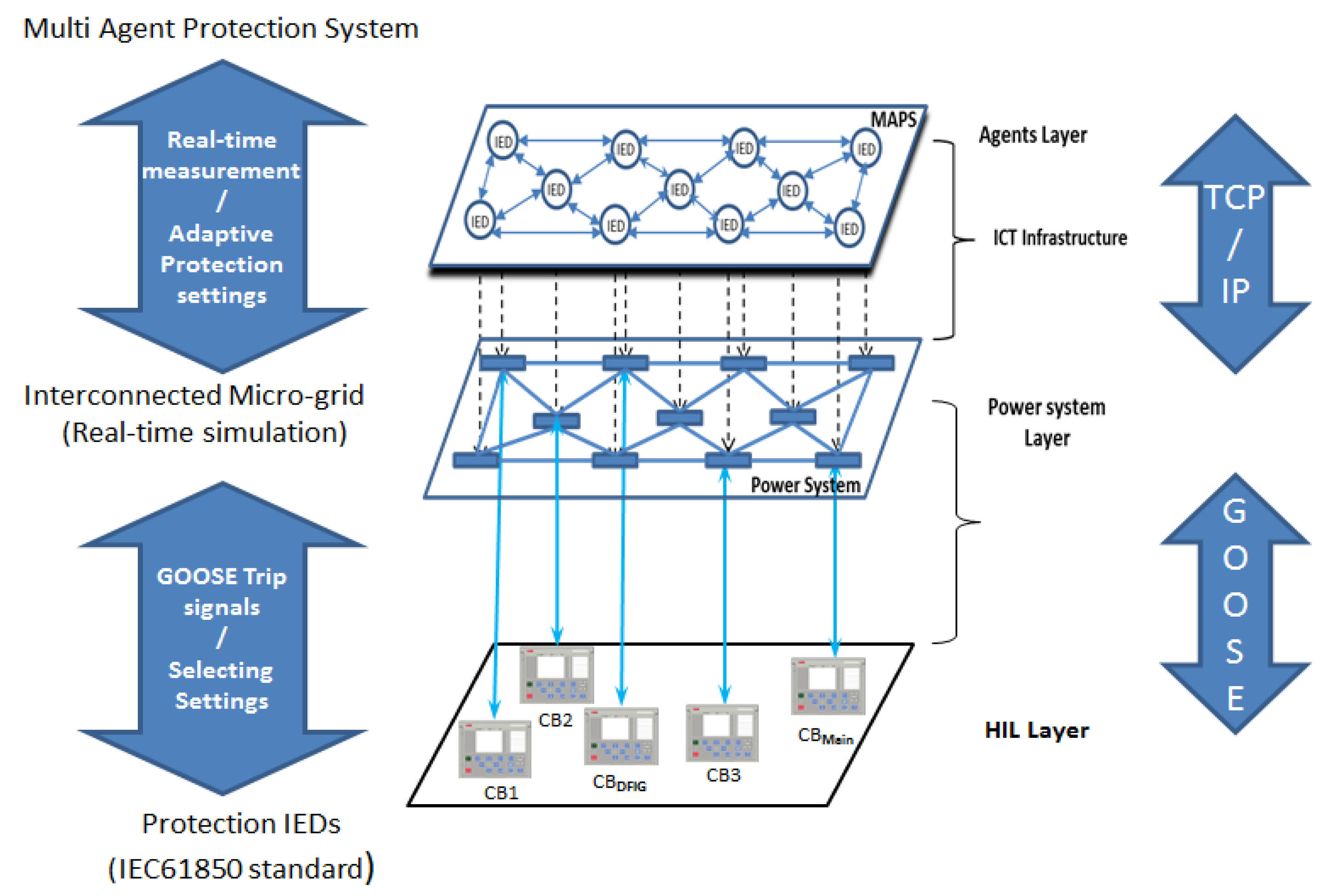
4.1. Layered Architecture

The establishment of simulation platform for MAPS is defined on a multi-layered architecture where various subsystems and simulation domain solvers are coupled as an integrated system. In Figure 12, three layers of the simulation framework consisting of protection agents, power system components and protection IEDs have been illustrated. As shown in Figure 12, the concept of co-simulation between agent layer and power system has been introduced to couple two different simulation domains for exchanging real-time data between protection agents and power system components. The software tools which have been used for co-simulation are java agent development environment (JADE, Jade Software Corporation, Christchurch, New Zealand) and MATLAB/SIMULINK (MathWorks Inc., Natick, MA, USA where appropriate domain solvers are adopted to simulate protection agents and power system elements. Also, the communication protocol which has been used to synchronize real-time data exchange between SIMULINK and Agent layer is TCP/IP. The bottom layer represented in Figure 12 demonstrates HIL simulation techniques where protection IEDs are used to operate CBs in a SIMULINK simulation environment. The protection IEDs within the HIL layer have been configured for both publishing and receiving generic object oriented substation event (GOOSE) messages to send trip signals to a real-time simulation model of the power system and also adjustment of the protection settings in protection IEDs upon receiving GOOSE messages from an IEC61850 module configured in a real-time digital simulation model [38]. Finally, in Figure 12, communication protocols and exchanged information between different simulation environments have been represented by a two-sided arrow on the right and left sides of the layered architecture for MAPS development.

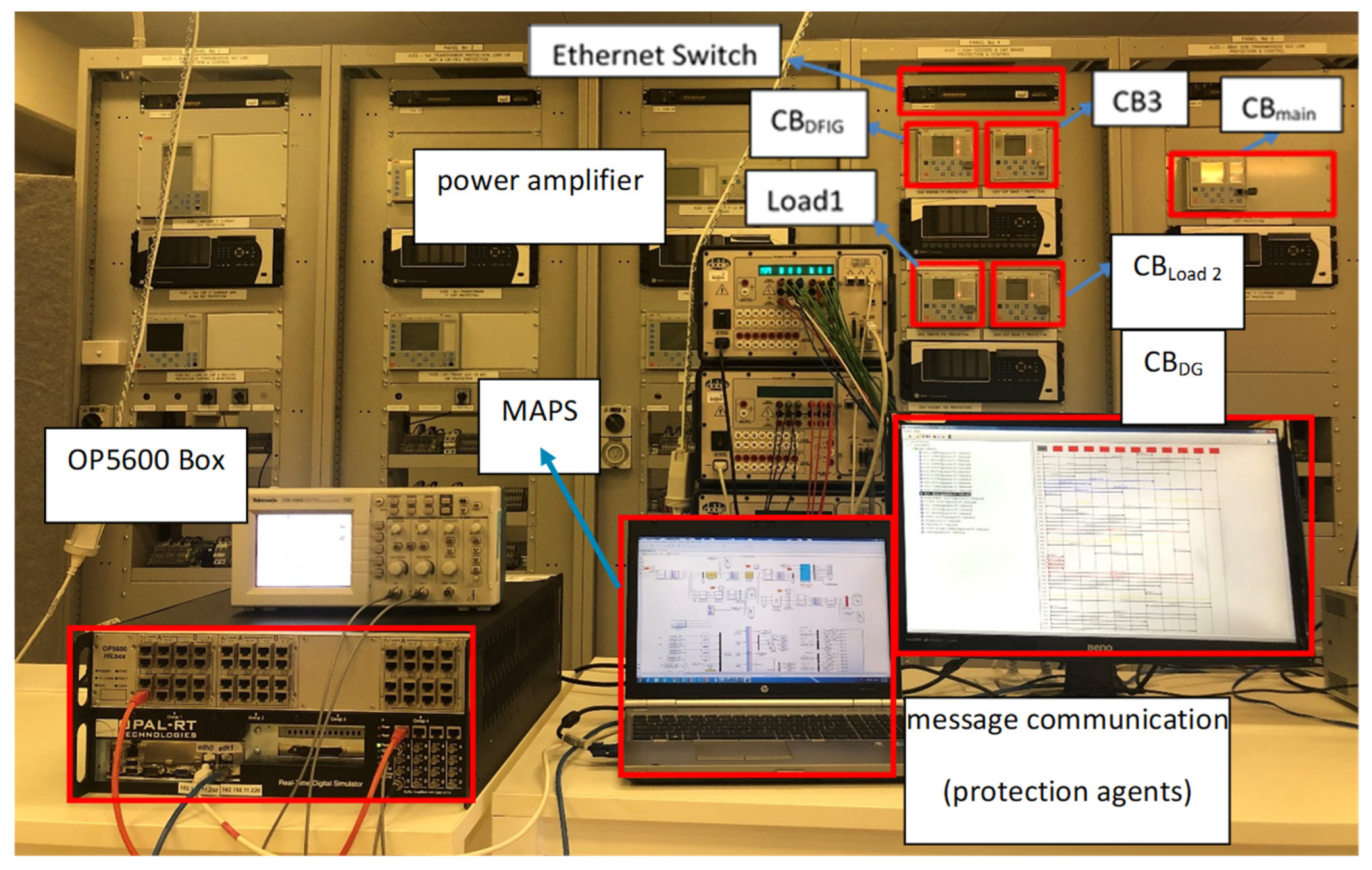
4.2. Testbed Platform

Following the proposed architecture for simulation framework of MAPS, developing testbed platforms to interface different hardware and software tools is critical to credibility and reproduction of simulation results under a real-world operation scenario. Therefore, a testbed platform integrating all the functional layers within MAPS has been developed where ICT infrastructure is embedded as communication medium to exchange real-time data between different components. In Figure 13, a testbed platform developed in the Victoria University Zone Substation (VUZS) laboratory has been illustrated where different hardware equipment including a real-time digital simulator (OPAL-RT-OP5600, Opal RT Technologies, Montreal, QC, Canada) protection IEDs (ABB-REF615, ABB Power Grids Australia Pty Limited, Queensland, Australia) power amplifier test unit (Doble-F6150e, Doble Engineering Company, Marlborough, MA, USA) a laptop and communication accessories such as Ethernet switches and cables have been used.
Basically, utilization of a real-time digital simulator is crucial to develop the testbed platform since interactions between different subsystems have to be matched with timescales in real-world operation scenarios. Consequently, for the Simulink model of the power system, RT-LAB software (OPAL-RT-OP5600, Opal RT Technologies, Montreal, QC, Canada) is used to deploy a power system model on the OP5600 real-time simulator box where real-time simulation data are communicated with the agent layer using the TCP/IP protocol and Ethernet cards on both the OP5600 and the laptop. For the HIL subsystem there are five ABB protection IEDs which are configured based on the IEC61850 standard to publish GOOSE messages to trip CBs in real-time Simulink model. Moreover, group settings within the protections IEDs are subscribed to GOOSE messages published by OP5600 forwarding protection settings determined by MAPS. Also, for simultaneous interaction between protection IEDs within the HIL subsystem and real-time power system running on the OP5600, a three phase amplifier test unit has been configured to inject real-time signals from CTs and VTs at the terminal of the ABB IEDs to replicate the voltage and current signals sensed by IEDs. Finally, MAPS has been deployed on the laptop equipped with multi-core processor capability due to the intensive computational tasks required to exchange and monitor protection age messages within the centralized processing unit [24].

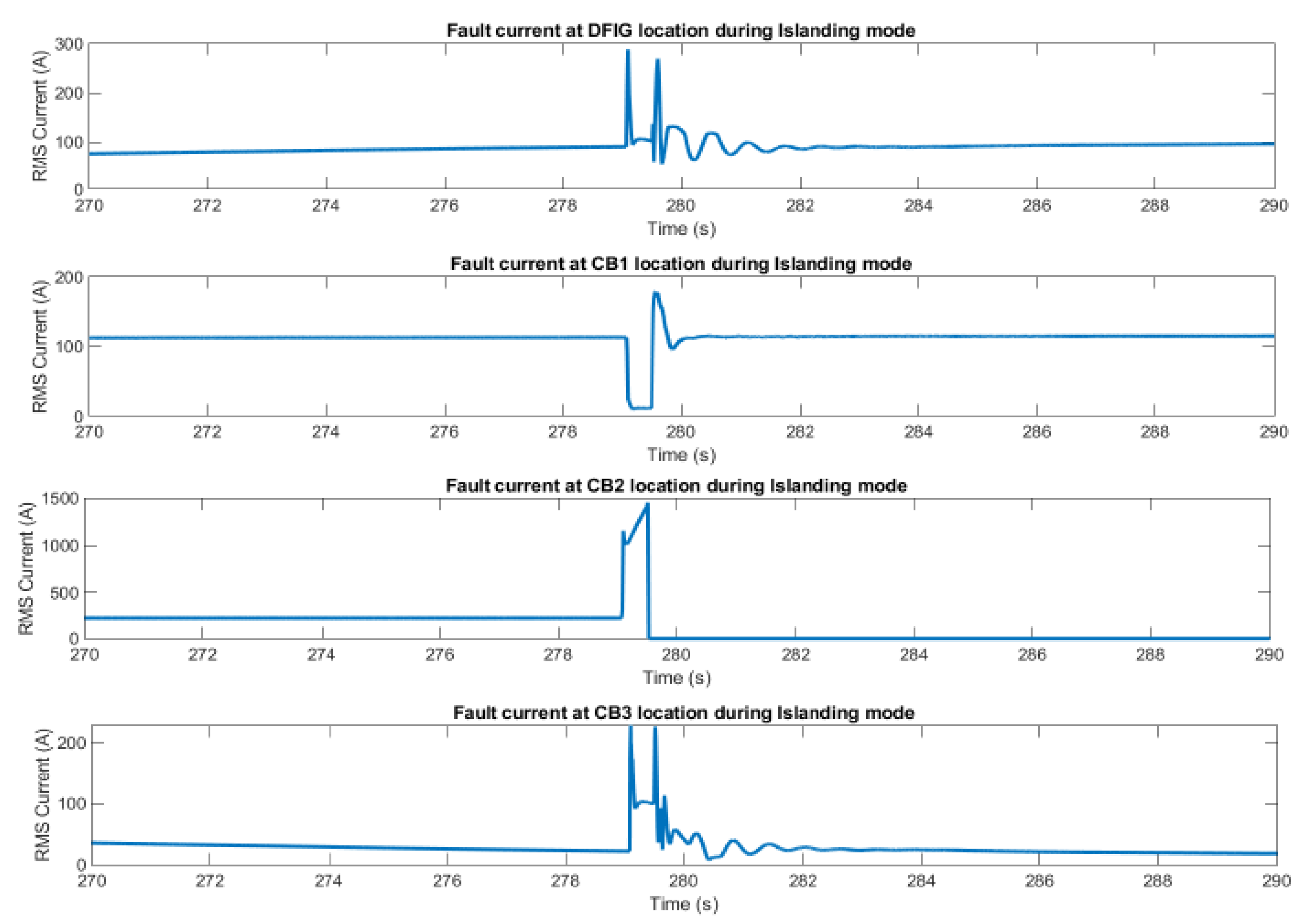
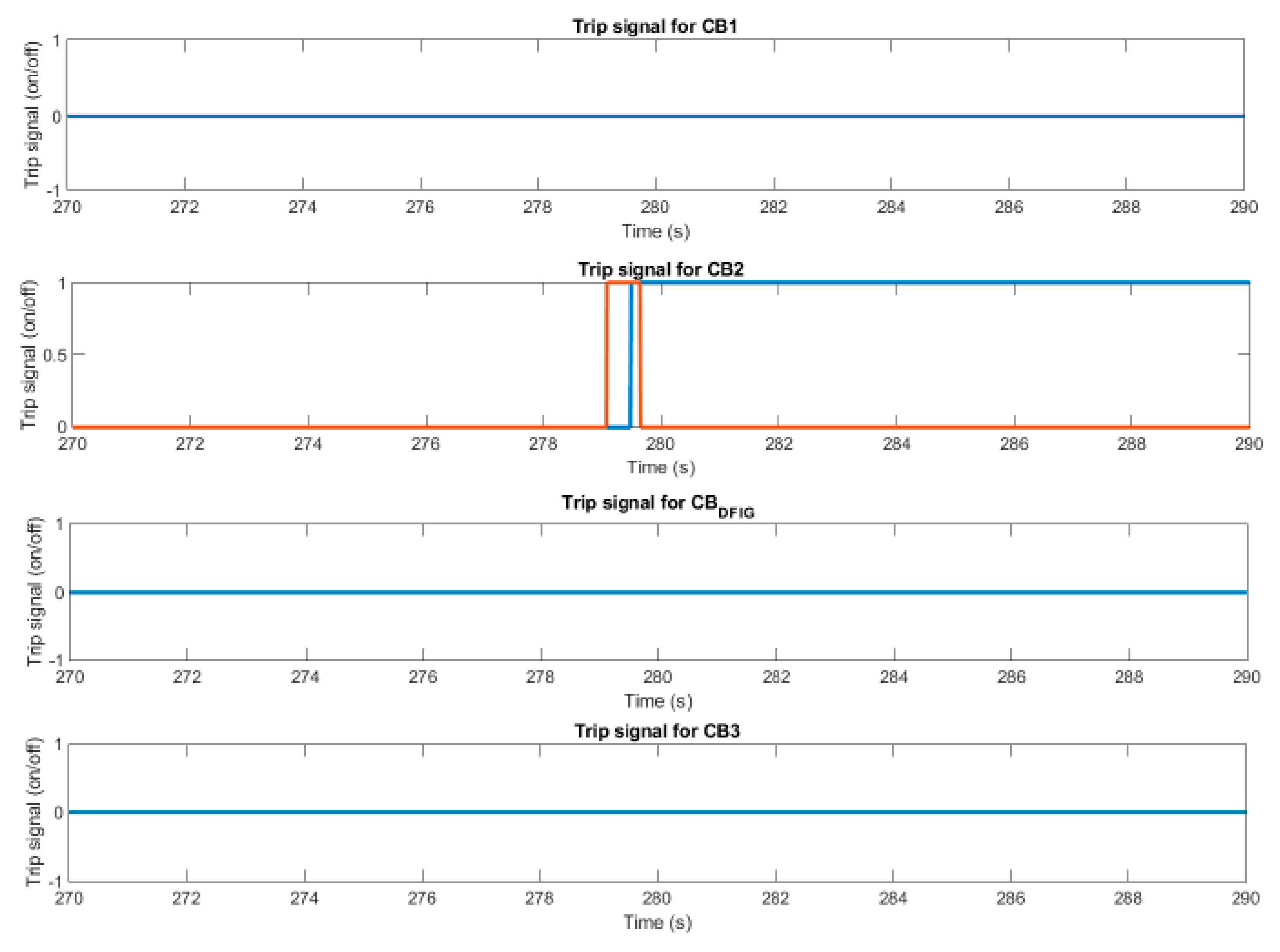
5. Simulation Results

The final stage in establishment of MAPS is to investigate and validate different aspects related to functionalities and performance of the proposed methodology considering real-world operation scenarios. Thus, having explained the process of decision making and adjustment of protection settings within MAPS, in this section two main characteristics/factors related to system protection task and cooperation between protection agents are demonstrated to compare the capability of proposed system protection approach in dealing with complexities in interconnected distribution networks. In the following subsections, real-time simulation scenarios based on the testbed setup developed in the previous section are studied to highlight the performance of MAPS under real-world operating conditions.

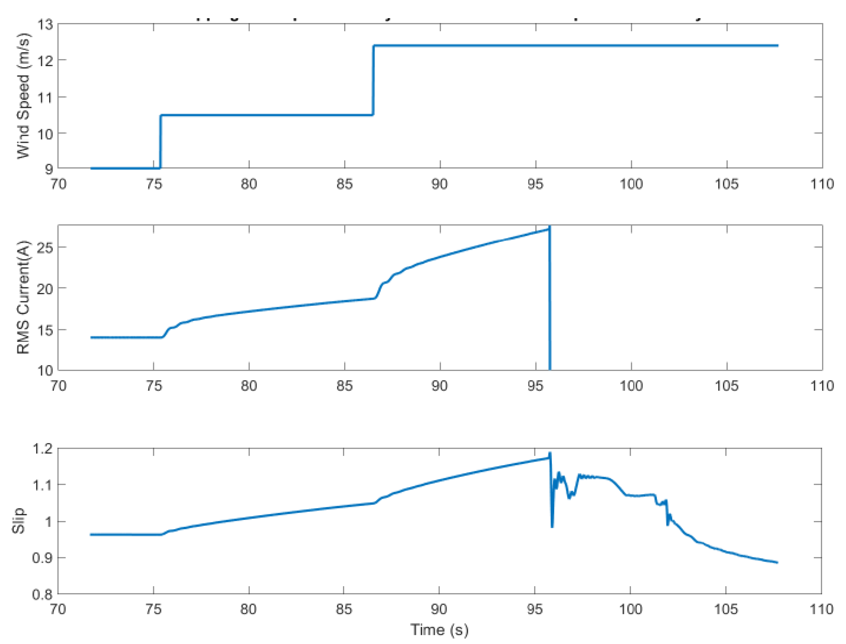
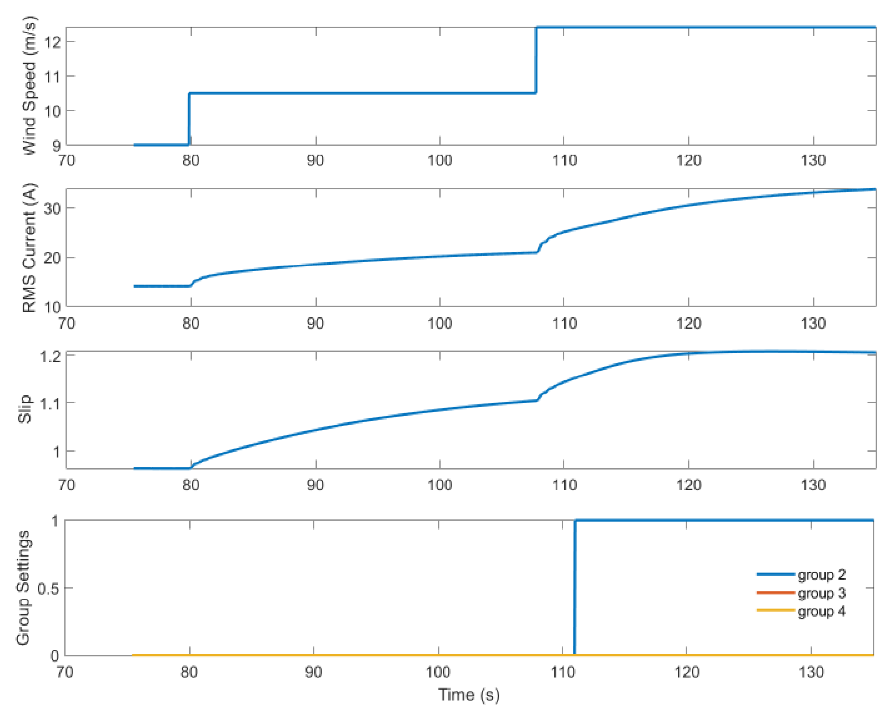
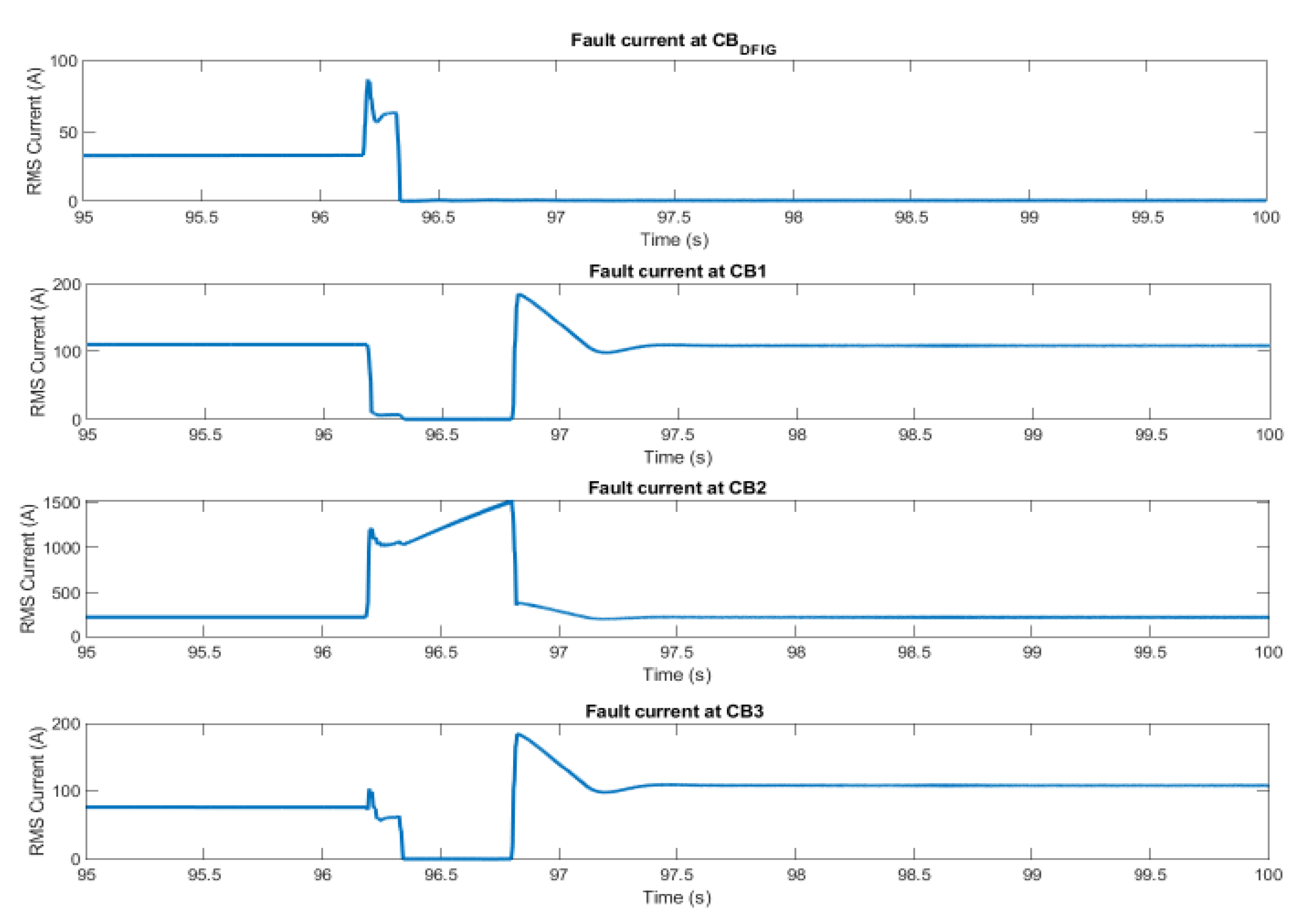
5.1. MAPS Performance

For the first scenario to evaluate the performance of MAPS against a conventional system protection setting, the effect of wind speed intermittencies on the operation conditions of the DFIG system is considered as an important factor to introduce complexities for system protection within an interconnected distribution network. Therefore, in order to evaluate potential drawbacks inherent to conventional protection settings in response to state transitions at the DFIG system connection point, a variation of the wind speed is simulated as a step input where the wind speed changes from 9 m/s to 12.5 m/s. In Figure 14, time domain responses of the RMS current and operation slip for DFIG system are plotted for step inputs of wind speed variation. As seen in Figure 14, under normal operating conditions, a state transition occurs due to the increase in wind speed which also leads to an increase in the RMS current at CBDFIG.
The trip signal triggered for CBDFIG is due to the fact that the DFIG system output power increases by the cube of the wind speed where in a conventional protection approach with fixed protection settings for TOC curves changes in wind speed can affect the loading current at the DFIG system and initiate a false trip at CBDFIG. However, with the introduction of MAPS and its intelligent adaptive characteristics, TOC curves are adjusted using pre-determined group settings to avoid false tripping. To investigate the effective approach proposed by MAPS, a similar operation scenario for variation of wind speed as input to the DFIG system is applied where protection agents are deployed on protection IED nodes. In Figure 15, step inputs for wind speed variation has been shown as the wind speed changes from 9 m/s to 12.5 m/s. Also, the RMS current and operation slip have been illustrated as the state transition occurs following changes in wind speed. Despite the same time domain responses for the RMS current and operation slip, CBDFIG remains closed while the wind speed increases. As shown in the bottom plot of Figure 15, the protection settings group within the protection IED is adjusted online using MAPS and its heuristic decision-making strategy explained in the previous section. Therefore, using an advanced protection scheme to adjust protection settings is inevitable to address false tripping for DER such as DFIG systems as intermittencies of renewable energies can introduce state transitions at their connection points. The settings within the protection IEDs are four different IEC TOC curves which have been pre-configured for different fault current characteristics and selected based on GOOSE signals received from MAPS. Arrangement to select different IEC TOC curves depends on the binary data within the GOOSE message which is represented by three binary bits. If the three binary bits are (0,0,0) then it is the default IEC TOC curves setting and if the binary bit is (1,0,0) it is the second IEC TOC curves which is selected in protection IEDs and etc. As seen in Figure 15, following the changes in wind speed (top plot in Figure 15) the protection setting is changed from default IEC curve as GOOSE message and the IEC TOC curve for the second settings (1,0,0) is selected (bottom plot in Figure 15).
Another important operating condition for an interconnected distribution network is islanded mode operation where reliability and accurate operation of the protection system is critical for both power system quality and stability of the interconnected distribution network. Thus, an operation scenario for comparing system protection performance under islanded mode has been introduced for both a conventional protection system and the proposed MAPS to highlight its potential capabilities to deal with protection challenges within the interconnected distribution network. For islanded mode operation, a 3-phase fault scenario at CB2 location is applied to evaluate time-domain response of the protection system. In Figure 16, multiple plots are shown to present the fault current at different CB locations during fault period of 0.3 s. As it is obvious from Figure 16, due to low mass inertia and the reduced level of fault current contribution during islanded mode operation at CB2 (the 3rd plot from the top), the protection IED does not detect the fault in its protection zone. However, for DFIG system (the 1st plot from the top), although the faulty section of the line is located upstream of DFIG system at the lateral feeder close to load 2 (CB2), due to unresponsive setting for fault at CB2 location, sympathetic tripping occurs at CBDFIG. Similarly, the problem related to aforementioned system protection challenge is rooted in a conventional protection strategy where fixed protection settings are adopted to address various operating conditions within an interconnected distribution network.
Having highlighted the drawbacks associated with the performance of system protection settings based on conventional approaches, MAPS has been integrated to explore the potential of the heuristic decision-making for improvement of the system protection functionalities in a typical interconnected distribution network. Therefore, a similar fault scenario under islanded operating mode has been introduced to evaluate MAPS for practical solutions to the complexities of system protection with respect to dynamic transitions of the interconnected distribution network into islanded mode. In Figure 17, time domain responses of the RMS currents at various CB locations in interconnected distribution network have been illustrated. As seen in Figure 17 and in opposition to conventional protection system, in MAPS CB2 (the 3rd plot from the top) operates and isolates the faulty section of the line selectively and in coordination with CBDFIG. This basically confirms that incorporation of distributed adaptive intelligent protection strategy can further improve system protection reliability during islanded mode of operation.
In Figure 18, the trip signals received from protection IEDs used for HIL configuration of the protection IEDs have been represented where trip signal for CB2 (the 2nd plot from the top-solid blue line) is activated to open CB2 within real-time simulation environment in MATLAB/SIMULINK as other CBs remain closed.

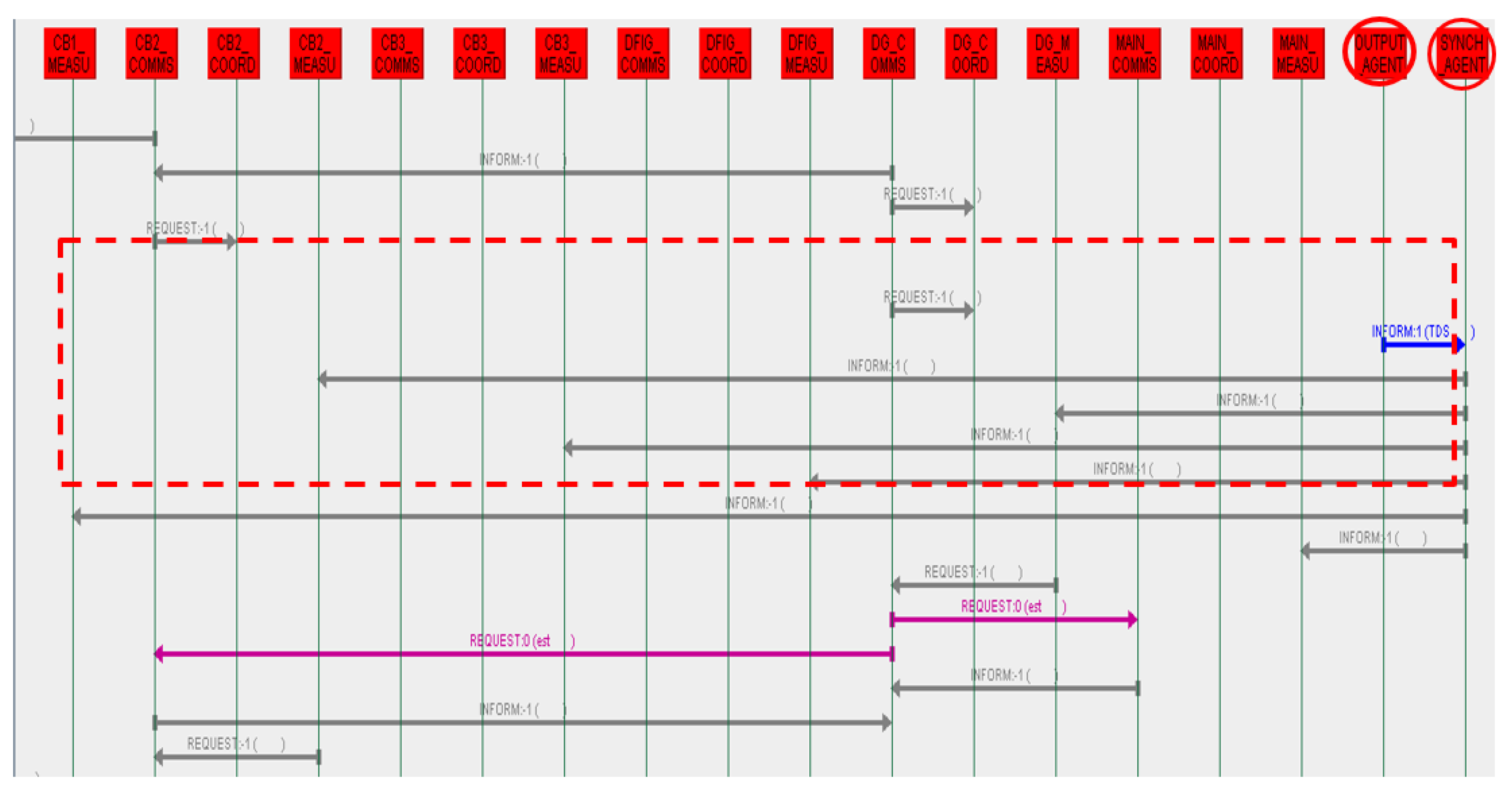
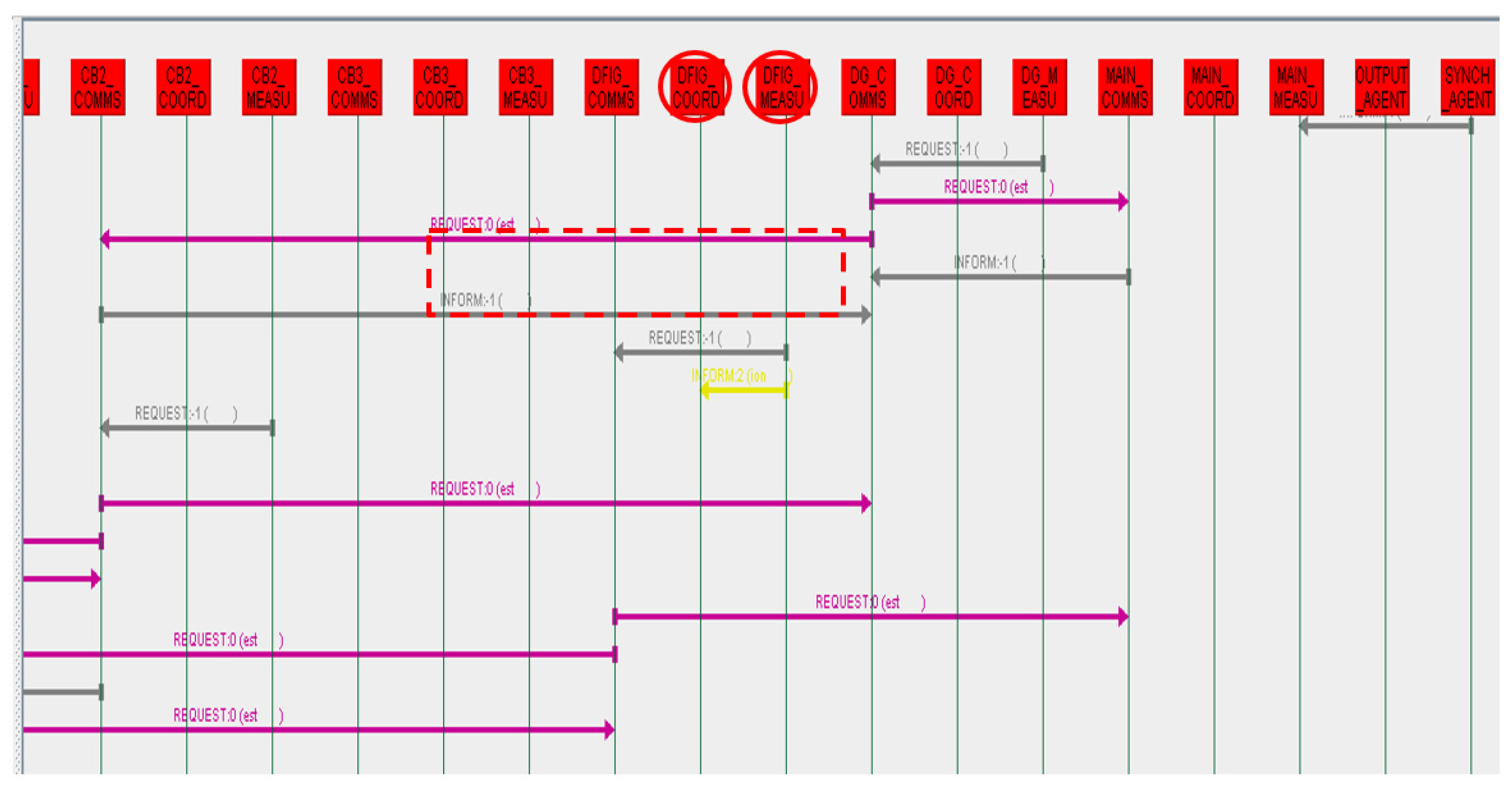
5.2. Agent Messageing and Knowledge Sharing

One of the important aspects in development of MAPS is its capability to exchange and share knowledge between different protection IED nodes which is critical to implement distributed decision making and adjustment of protection settings under various operation scenarios. However, to ensure the credibility of messaging sequences and designated agent behaviour to fulfil the protection task, co-simulation between power system components and protection agents has been established to reproduce real-time interactions between two different simulation domains. Thus, in synchronization to exchange real-time measurement data and protection settings within co-simulation framework, two different agents, SYNCH agent and OUTPUT agent are developed to automatically coordinate the interactions between agent layer and interconnected distribution network. For the SYNCH agent, the main task is defined to establish a TCP/IP connection and received array of real-time measurement data from real-time simulator (OP5600) and publish it to measurement agents within the agent layer. Similarly, the OUTPUT agent receives messages from coordination agents and send it to the SYNCH agent to update protection settings within protection IEDs in HIL layer. In Figure 19, establishment of the co-simulation through synchronization of data exchange between agent layer and power system layer have been shown where messages from SYNCH and OUTPUT agents are represented by a dashed line border.
Although interfacing between the agent layer and power system is addressed through synchronization tasks, t knowledge sharing between protection agents is associated with agent types and behaviour which are defined for each agent to fulfil their protection tasks within the agent layer. For example, for a DFIG system as the state transition by measurement agent a coordination message is sent to a coordination agent to request an update on protection settings using the proposed decision-making process. As seen in Figure 20, the coordination message (dashed line border) sent by the DFIG system is received by a DFIG coordination agent which has been deployed to use the knowledge database system to select proper protection settings for the specified operating conditions.

6. Conclusions

Given the complexities for fault current behaviour in interconnected distribution networks, development of a reliable and efficient protection system is dependent on many factors such as athe vailability of renewable energy resources (wind, solar radiation, etc.), the number of DER connected into the grid and the types of the DER with the control strategies embedded by the original equipment manufacturer (OEM). In this paper, a new approach based on integrating MAS and distributed decision making has been adopted to deal with system protection challenges within a distribution network interconnected with DFIG wind turbine systems. The significance for the proposed methodology is concerned with distributed decision-making based on knowledge representation of the system protection using domain-specific ontology which is consistent to human mind logic. Further to that, a knowledge engineering process based on generalization of system protection knowledge into human mind cause-effect reasoning process where a rule-based knowledge database established to support decision making similar to an expert system. The main advantages for the proposed MAPS are associated to scalability and interoperability of the proposed protection system which are critical factors for large-scale, heterogeneous and interdependent future power systems. Moreover, using element of distributed artificial intelligence such as MAS has been shown to be effective to enable proposed MAPS for taking into consideration the operation information across neighbouring nodes for decision-making and accordingly adjust the protection settings. Finally, the MAPS performance and its messaging capabilities have been verified using real-time co-simulations and HIL techniques to meet the requirements for real-world operation scenarios.

Author Contributions

Conceptualization and development, P.P.; Methodology, P.P.; Software, P.P.; Resources, A.K.; Validation, P.P.; Writing and editing, P.P., A.K. and J.S. All authors have read and agreed to the published version of the manuscript.

Funding

This research received no external funding.

Acknowledgments

The authors would like to thank OPAL-RT for supporting this research with special thanks to Christy Genganantha technical support and Jean Belanger for providing the OP5600 real-time digital simulator equipment during our research studies. We are also immensely grateful to Vitoria University and Professor Stephen Gray, the Director of the Institute of Sustainable Industries and Liveable Cities (ISILC) for approving the on campus access for running experiments using VUZS laboratory.

Conflicts of Interest

The authors declare no conflict of interest.

Appendix A. Simulation Data

Table A1, Table A2, Table A3, Table A4 and Table A5 below represents simulation data for DFIG system and other power system components including DG, distribution lines and 3-phase two winding transformers.
Table A1. Simulation Data for DFIG Induction Generator.
DFIG-Induction Generator
Rated Power & Frequency1.5 × 106/0.9 (VA), 60 Hz
Stator Voltage575 (L-L) Vrms
Rotor Voltage1975 (L-L) Vrms
Stator & Rotor Resistance0.023, 0.016 pu
Stator & Rotor Leakage Inductance0.18, 0.16 pu
Magnetizing Inductance2.9 pu
Inertia Constant0.685 s
Pole pairs3
Table A2. Data for DFIG Wind Turbine Blade.
DFIG-Wind Turbine Blade
Turbine Power1.5 MW
Inertia Constant4.32 s
Shaft Spring1.11 pu
Shaft Mutual Damping1.5 pu
Table A3. Simulation data for 3-Phase two windings Transformer Connecting DFIG System.
DFIG-Transformer
Rated Power & Frequency1.75 × 106 (VA), 60 (Hz)
Winding 1 (V1, R1, Ll)(25 × 103 (L-L) Vrms, 0.025/30 pu, 0.025 pu)
Winding 2 (V2, R2, L2)(575 (L-L) Vrms, 0.025/30 pu, 0.025 pu)
Table A4. Simulation Data for Synchronous Generator of the DG System.
DG-Synchronous Generator
Rated Power & Frequency15 × 106 (VA), 60 Hz
Terminal Voltage25 × 103 (L-L) Vrms
Stator Resistance0.003 pu
Reactances (Xd, Xd′, Xd″, Xq, Xq′, Xq″)(1.305, 0.296, 0.252, 0.474, 0.243, 0.18)
Time Constants-Open Circuit (Tdo, Tdo′, Tq″)(4.49, 0.0681, 0.0513) pu
Inertia Constant3.7 pu
Pole pairs1
Table A5. Simulation Data for Distribution Line.
Parameters of Distribution Lines
Positive and Zero Sequence Resistances (Ohm/km)(0.1153, 0.413)
Positive and Zero Sequence Inductances (H/km)(1.05 × 10−3, 3.32 × 10⁻³)
Positive and Zero Sequence Capacitances (F/km)(11.33 × 10−9, 5.01 × 10⁻⁹)

References

  1. Al-Sumaiti, A.S.; Salama, M.M.A. Review on issues related to electric energy demand in distribution system for developing countries. In Proceedings of the 3rd IET International Conference on Clean Energy and Technology (CEAT), Kuching, Malaysia, 24–26 November 2014; pp. 1–6. [Google Scholar]
  2. Saad Al-Sumaiti, A.; Kavousi-Fard, A.; Salama, M.; Pourbehzadi, M.; Reddy, S.; Rasheed, M.B. Economic Assessment of Distributed Generation Technologies: A Feasibility Study and Comparison with the Literature. Energies 2020, 13, 2764. [Google Scholar] [CrossRef]
  3. Shahriari, S.A.A.; Abapour, M.; Yazdian, A.; Haghifam, M.R. Minimizing the Impact of Distributed Generation on Distribution Protection System by Solid State Fault Current Limiter. In Proceedings of the IEEE PES T&D 2010, New Orleans, LA, USA, 19–22 April 2010; pp. 1–7. [Google Scholar] [CrossRef]
  4. Tang, W.-J.; Yang, H.-T. Data Mining and Neural Networks Based Self-Adaptive Protection Strategies for Distribution Systems with DGs and FCLs. Energies 2018, 11, 426. [Google Scholar] [CrossRef] [Green Version]
  5. Escobar, A.; Saadeh, M.; Balda, J.C.; Bourne, J.; Feng, Y.; Mantooth, H.A. A methodology to coordinate solid-state fault current limiters with conventional protective devices. In Proceedings of the IEEE/PES Power Systems Conference and Exposition, Phoenix, AZ, USA, 20–23 March 2011; pp. 1–6. [Google Scholar]
  6. Bagriyanik, M.; Cakal, G.; Bagriyanik, F.G. The Effect of Fault Current Limiters on Distribution Systems with Wind Turbine Generators. Int. J. Renew. Energy Res. 2013, 3, 149–154. [Google Scholar]
  7. Bayati, N.; Sadeghi, S.; Hosseini, A. Optimal Placement and Sizing of Fault Current Limiters in Distributed Generation Systems Using a Hybrid. Genetic Algorithm. Eng. Technol. Appl. Sci. Res. 2017, 7, 1329–1333. [Google Scholar] [CrossRef]
  8. Rockefeller, G.D.; Wagner, C.L.; Linders, J.R.; Hicks, K.L.; Rizy, D.T. Adaptive transmission relaying concepts for improved performance. IEEE Trans. Power Deliv. 1988, 3, 1446–1458. [Google Scholar] [CrossRef]
  9. Brahma, S.M.; Girgis, A.A. Development of adaptive protection scheme for distribution systems with high penetration of distributed generation. Power Deliv. IEEE Trans. 2004, 19, 56–63. [Google Scholar] [CrossRef]
  10. Oudalov, A.; Fidigatti, A. Adaptive network protection in microgrids. Int. J. Distrib. Energy Resour. 2009, 5, 201–226. [Google Scholar]
  11. Sung, B.C.; Lee, S.H.; Park, J.W.; Meliopoulos, A.P.S. Adaptive Protection Algorithm for Overcurrent Relay in Distribution System with DG. J. Electr. Eng. Technol. 2013, 8. [Google Scholar] [CrossRef] [Green Version]
  12. Laaksonen, H.; Ishchenko, D.; Oudalov, A. Adaptive protection and microgrid control design for Hailuoto Island. In Proceedings of the 2014 IEEE PES General Meeting|Conference & Exposition, National Harbour, MD, USA, 27–31 July 2014; p. 1. [Google Scholar]
  13. Rockefeller, G.D. Feasibility of adaptive protection and control. IEEE Trans. Power Deliv. 1993, 8, 975–983. [Google Scholar] [CrossRef]
  14. Vasileios, A.P.; Korres, G.N.; Hatziargyriou, N.D. Protection coordination in modern distribution grids integrating optimization techniques with adaptive relay setting. In Proceedings of the IEEE Eindhoven PowerTech, Eindhoven, The Netherlands, 29 June–2 July 2015; pp. 1–6. [Google Scholar]
  15. Maleki, M.G.; Javadi, H.; Khederzadeh, M.; Farajzadeh, S. An Adaptive and Decentralized Protection Scheme for Microgrid Protection. In Proceedings of the Power System Protection and Control Conference (PSPC), Tehran, Iran, 19–20 January 2016. [Google Scholar]
  16. Bahadornejad, M.; Merrington, N.R.; Nair, N.K.C. An Innovative Method for Re-setting Over-current Relays in Active Radial Distribution System. In Proceedings of the 2018 Australasian Universities Power Engineering Conference (AUPEC), Auckland, New Zealand, 27–30 November 2018; pp. 1–6. [Google Scholar]
  17. Coury, D.V.; Thorp, J.S.; Hopkinson, K.M.; Birman, K.P. Agent Technology Applied to Adaptive Relay Setting for Multi-Terminal Lines. In Proceedings of the 2000 Power Engineering Society Summer Meeting, Seattle, WA, USA, 16–20 July 2000. [Google Scholar]
  18. Abedini, R.; Pinto, T.; Morais, H.; Vale, Z. Multi-agent approach for power system in a smart grid protection context. In Proceedings of the 2013 IEEE Grenoble Conference, Grenoble, France, 16–20 June 2013; pp. 1–6. [Google Scholar]
  19. Wong, S.K.; Kalam, A. Development of a power protection system using an agent based architecture. In Proceedings of the 1995 International Conference on Energy Management and Power Delivery EMPD ‘95, Singapore, 21–23 November 1995; Volume 431, pp. 433–438. [Google Scholar]
  20. Min, B.W.; Jung, K.H.; Choi, M.S.; Lee, S.J.; Hyun, S.H.; Kang, S.H. Agent-Based Adaptive Protection Coordination in Power Distribution Systems. In Proceedings of the 17th International Conference on Electricity Distribution, Barcelona, Spain, 12–15 May 2003. [Google Scholar]
  21. Qin, L.; Wang, Y.; Hao, C.; Li, M. Multi-Agent System wide area protection considering distributed generation impact. In Proceedings of the 2011 International Conference on Advanced Power System Automation and Protection, Beijing, China, 16–20 October 2011; pp. 549–553. [Google Scholar]
  22. Ming-Yu, Y.; Yong-Li, Z. A Cooperative Protection System with Multi-Agent System. In Proceedings of the Transmission and Distribution Conference and Exhibition: Asia and Pacific, 2005 IEEE/PES, Dalian, China, 18 August 2005; pp. 1–4. [Google Scholar]
  23. Lim, I.H.; Lee, S.J.; Choi, M.S.; Crossley, P. Multi-Agent System-based Protection Coordination of Distribution Feeders. In Proceedings of the Intelligent Systems Applications to Power Systems, Niigata, Japan, 5–8 November 2007; pp. 1–6. [Google Scholar]
  24. Peidaee, P.; Kalam, A.; Shi, J. A Real-Time Simulation Framework for System Protection in Smart Grid Applications. In Proceedings of the 2018 Australasian Universities Power Engineering Conference (AUPEC), Auckland, New Zealand, 27–30 November 2018; pp. 1–5. [Google Scholar]
  25. Peidaee, P.; Kalam, A.; Shi, J.; Jimenez, P. Fault Current Characteristics in Distribution Network Interconnected with DFIG. Int. Rev. Electr. Eng. 2015, 10. [Google Scholar] [CrossRef]
  26. Massoud, A. Toward Self-Healing Infrastructure Systems. Computer 2000, 33, 44–53. [Google Scholar] [CrossRef]
  27. Peidaee, P.; Kalam, A.; Moghaddam, M.H. Developing a simulation framework for integrating multi-agent protection system into smart grids. In Proceedings of the Australasian Universities Power Engineering Conference (AUPEC2017), Melbourne, VIC, Australia, 19–22 November 2017; pp. 1–6. [Google Scholar]
  28. Nikraz, M.; Caire, G.; Bahri, P.A. A methodology for the development of multi-agent systems using the JADE platform. Comput. Syst. Sci. Eng. 2006, 21, 99–116. [Google Scholar]
  29. González-Briones, A.; De La Prieta, F.; Mohamad, M.S.; Omatu, S.; Corchado, J.M. Multi-Agent Systems Applications in Energy Optimization Problems: A State-of-the-Art Review. Energies 2018, 11, 1928. [Google Scholar] [CrossRef] [Green Version]
  30. Sujil, A.; Verma, J. Multi Agent System: Concepts, Platforms and Applications in Power Systems; Springer: Dordrecht, The Netherlands, 2018; Volume 49. [Google Scholar]
  31. Rebizant, W.; Szafran, J.; Wiszniewski, A. Decision Making in Protective Relays. In Digital Signal Processing in Power System Protection and Control; Springer: London, UK, 2011; pp. 199–218. [Google Scholar] [CrossRef]
  32. Stephanus, A.; Ananda, J.-C.G. Multi-agent Based Protection on Highly Dominated Distributed Energy Resources. Eng. Inf. Inst. 2013, 10, 927–931. [Google Scholar]
  33. Soroudi, A.; Amraee, T. Decision making under uncertainty in energy systems: State of the art. Renew. Sustain. Energy Rev. 2013, 28, 376–384. [Google Scholar] [CrossRef]
  34. Albar, F.M.; Jetter, A.J. Heuristics in decision making. In Proceedings of the PICMET ‘09—2009 Portland International Conference on Management of Engineering & Technology, Portland, OR, USA, 2–6 August 2009; pp. 578–584. [Google Scholar]
  35. Katyara, S.; Staszewski, L.; Leonowicz, Z. Protection Coordination of Properly Sized and Placed Distributed Generations–Methods, Applications and Future Scope. Energies 2018, 11, 2672. [Google Scholar] [CrossRef] [Green Version]
  36. Bakr, H.M.; Shaaban, M.F.; Osman, A.H.; Sindi, H.F. Optimal Allocation of Distributed Generation Considering Protection. Energies 2020, 13, 2402. [Google Scholar] [CrossRef]
  37. Ebe, F.; Idlbi, B.; Stakic, D.E.; Chen, S.; Kondzialka, C.; Casel, M.; Heilscher, G.; Seitl, C.; Bründlinger, R.; Strasser, T.I. Comparison of Power Hardware-in-the-Loop Approaches for the Testing of Smart Grid Controls. Energies 2018, 11, 3381. [Google Scholar] [CrossRef] [Green Version]
  38. Palensky, P.; van der Meer, A.; Lopez, C.; Joseph, A.; Pan, K. Applied Cosimulation of Intelligent Power Systems: Implementing Hybrid Simulators for Complex Power Systems. IEEE Ind. Electron. Mag. 2017, 11, 6–21. [Google Scholar] [CrossRef]
Figure 1. System protection scenario for the proposed interconnected distribution network.
Energies 13 05250 g001
Figure 2. Bar chart representing the variation in loading current at the DFIG system.
Energies 13 05250 g002
Figure 3. The effect of wind speed on the loading current of the DFIG system.
Energies 13 05250 g003
Figure 4. Variation in fault current contribution under grid-connected/islanded mode operation.
Energies 13 05250 g004
Figure 5. Unresponsive TOC curve for fault at different locations due to grid-connected/islanded mode.
Energies 13 05250 g005
Figure 6. Use case representing interactions in the proposed MAPS.
Energies 13 05250 g006
Figure 7. UML Sequence diagram for agent interaction to update protection settings within MAPS.
Energies 13 05250 g007
Figure 8. State transitions due to variation in DFIG system operation conditions.
Energies 13 05250 g008
Figure 9. Ontology based knowledge representation for protection system within interconnected distribution network.
Energies 13 05250 g009
Figure 10. Knowledge database developed in PROLOG to automate selection of protection settings within the proposed MAPS.
Energies 13 05250 g010
Figure 11. Flowchart representation of the stages in updating group settings within MAPS.
Energies 13 05250 g011
Figure 12. Architectural layers for developing co-simulation and HIL to simulate real-time MAPS.
Energies 13 05250 g012
Figure 13. Simulation platform for MAPS developed at the VUZS laboratory.
Energies 13 05250 g013
Figure 14. Time domain simulation representing false-tripping due to wind speed variation in the DFIG system.
Energies 13 05250 g014
Figure 15. Real-time adjustment in protection settings for DFIG system.
Energies 13 05250 g015
Figure 16. Sympathetic tripping of CBDFIG for fault 2 at CB2 location in a conventional protection system.
Energies 13 05250 g016
Figure 17. Selectivity of tripping CB2 for fault 2 integrating MAPS.
Energies 13 05250 g017
Figure 18. Trip signals received from protection IEDs simulating CBs operation in real-time for power system.
Energies 13 05250 g018
Figure 19. Messaging coordination to synchronize real-time interactions between the agent layer and the power system.
Energies 13 05250 g019
Figure 20. Message communication between protection agents within the protection IED at the CBDFIG in MAPS.
Energies 13 05250 g020
Table 1. System knowledge representing subjective elements for decision making.
System Knowledge Database
CBiTypeUp/Down StreamTransition States
DFIGWTUpstream4
Load1LDDownstream1
Load2LDDownstream1
TieCBUp/Down5
DGDGUpstream2
MAINMGUpstream2 (GC-IS)

