1. Introduction
The global economy remains subject to ongoing structural changes but it is still based on fossil raw materials. In particular, this applies to the energy sector. Changes in this market are mainly related to environmental protection and have resulted in the dynamic development of unconventional energy sources [
1,
2]. The amount of energy obtained from these sources, however, is not sufficient to cover the huge and constantly growing overall demand for energy. This in turn means that in many countries energy is still produced from conventional energy sources, including hard coal. The most popular way of obtaining this raw material, due to its retention, is underground mining.
Strong competition on the energy raw materials market causes that mining companies strive to reduce production costs. One way to achieve this is to constantly increase the efficiency of machines such as high-performance longwall systems designed for coal mining. Longwall shearers and plow system are machines that mine the rock mass. The output is transported by scraper and belt conveyors [
3,
4,
5,
6]. The roof support controls key functions in the longwall complex such as securing the roof which is the working space in the longwall and moves the entire complex along with the progress of exploitation [
7,
8,
9,
10]. An active longwall and the machines of the longwall complex are presented in
Figure 1.
The powered roof support secures the longwall excavation against deformation caused by the rock mass. At the same time, this type of impact is also generated by the floor and roof as well as by the cave-in area. The biggest threat to the support is generated by the roof in which the stress resulting from the imbalance in the rock mass is most often concentrated. The disturbance of this balance caused by mining activity results in various types of loads acting on the support.
The geological and mining conditions of the coal production process constantly change. Consequently, loads impacting on the roof support have different values, directions and nature (static, dynamic, quasi-static). This diversity means that the construction and technical parameters of the support must be properly selected so as to ensure full functionality necessary for the operation process. This, in turn, means that a wide range of scientific work should be focused on improving and, above all, adapting to changing conditions. The powered roof support consists of individual but cooperating sections (
Figure 1). Each element impacts on the remaining components. Therefore, tests should include all sub-assemblies and elements of the section.
The main sub-assemblies of the section that determine its operating parameters are hydraulic cylinders, and the entire system of hydraulic supply and control. The powered roof support is a hydraulic machine, powered by high pressure, whose energy carrier is oil and water concentrate. Spragging of the support section of the powered support for the required height of the excavation and its support is conducted by hydraulic legs. They constitute a structural connection of the canopy and floor base. It can be assumed that the hydraulic legs, as the main executive elements of the support section, transfer external loads impacting on the support. At the same time, these legs are most vulnerable to damage and destruction due to the deformation effect of the rock mass. To prevent it, the leg’s hydraulic feed system is protected by a safety valve. The purpose of the safety valve is to prevent the hydraulic pressure in the leg’s cylinder from exceeding the allowable value.
The projected load (dynamic or static) determines the choice of type and parameters of the safety valve (response time, efficiency). It is also essential to determine the working pressure at which the safety valve will properly operate. This value is selected depending on the section design and mining and geological conditions prevailing in a given area. These conditions cannot be fully predicted due to the fact that the depth of exploitation of coal seams constantly increase. Greater depths are associated with an accumulation of various hazards and the impact previously conducted mining activities is visible. Consequently, there is a number of additional threats and hazards that occur during the coal mining process. These are mainly methane [
11,
12,
13,
14] and fire [
15,
16] hazards, very strongly dependent on the physical parameters of the goafs [
17,
18,
19], which also act on the support. Above all, the most dangerous is the deformation effect of the rock mass which can generate various types of loads impacting on the support.
All these factors mean that the work parameters of the legs and entire sections must be adapted to such load conditions. A system that is not properly adjusted may cause a threat to the safety of miners and disruption of the operation process. This can be prevented by developing comprehensive methodology for testing the entire section and its most important components and sub-assemblies in terms of their adaptation to various load conditions to which they may be subjected during operation.
While developing this methodology, it was assumed that it would be based on three basic pillars. The first will include the analysis of phenomena that may occur in the rock mass in which the support will work and the resulting types of loads that may affect it. The second pillar includes a set of testable key systems and components, and support section components under these loads. In this case, the selection of appropriate methods and the best possible mapping during their implementation of the actual state of load is crucial. The third pillar refers to legal conditions that govern the selection and admission of the support to work in given conditions. Appropriate and quick adaptation of directives, standards, and other regulations to dynamically changing conditions in which the system operates is of key importance.
The analysis of the literature in the field of testing and selection of a powered support and the impact of the rock mass on a support is very wide and diverse, and includes various aspects related to the use of mining support in longwall excavations [
20,
21,
22,
23,
24,
25,
26,
27,
28,
29]. Available papers refer to individual aspects of operation, but do not include a comprehensive assessment of these conditions and a method that would define the means to adapt the system. Legal conditions that have a significant impact on the practical application of research results are also not included. It can therefore be assumed that this paper is the first presenting an attempt to combine many factors impacting on the selection of a powered roof support.
This paper presents the concepts of the test procedure and the adaptation of the powered support to various mining and geological conditions. The main purpose of the work is to develop a comprehensive methodology based on research and practical experience. The data on mining and geological conditions in a given area helps to properly select a system.
The research team made an attempt to determine the potential loads that a support may be subjected to during operation by conducting an analysis of the phenomena occurring in the rock mass and their consequences. It was used to identify the most dangerous loads the support may be exposed to.
The obtained results were used as a basis for stands tests of hydraulic legs and the remaining equipment. The tests included dynamic impact loading in the form of free-falling mass and constant displacement. The tests included safety valves and the entire hydraulic system. The model tests included the hydraulic system of the leg with particular regard to the connections of safety valves. Model tests supplement costly bench test machines that require highly specialized equipment. They also provide new data in the field of flows and related speed and pressure distributions in these systems. The research area, located in the second pillar of the developed concept, was also supplemented with tests of the support’s control system.
The purpose of the research is to develop a new system for remote control of powered support sections. The use of such a system will allow control of the support from outside the longwall excavation, e.g., from a bottom gate. This, in turn, should significantly improve the safety of work in the area of direct exploitation. A special virtual system was developed to test these systems. The results of the tests carried out using this system are presented in the paper.
The third pillar, included in the presented concept, as already mentioned, refers to legal conditions regarding mining supports. The paper discusses only the essential legal acts in this field. These acts must also be considered when deciding whether a given support is suitable for underground operation.
The concept presented in the work, together with the results of specific research included in it, undoubtedly represents a new approach to research aimed at adapting powered roof supports to mining and geological conditions.
Therefore, one of the objectives is to answer the question of whether, based on the current state of knowledge, we are able to develop an effective method to select a powered roof support that will function properly in given changing mining and geological conditions. It is also important to determine the best methods and tools. It seems that this can be achieved with the use of the presented concept, including issues related to rock mechanics, fluid mechanics, mechanical engineering, computer science and control, as well as modelling, bench tests, and tests conducted in real conditions.
The presented method of research implementation, closely related to real phenomena occurring in the rock mass, constitute a new approach to testing sub-assemblies of the roof support section. It also includes a broader view of the problem of adapting roof supports to the conditions in which they will work.
Previous studies concerning roof supports did not cover such a comprehensive approach to this issue, including legal conditions. Practice shows that these conditions are very important and should take into account new research results and user’s opinions. So far, the tests have included the most essential aspects but they are focused mainly on individual problems [
20,
21,
22,
23,
24,
25]. They do not include such a comprehensive approach as presented in this paper.
The paper discusses the individual pillars of the developed concept for adapting support to diverse mining and geological conditions, along with examples of research that has been carried out in individual areas.
It should also be emphasized that the presented concept is open and can be freely modified depending on the needs and expectations. It should also be emphasized that the material presented in the paper extends the existing knowledge in the field of testing roof supports, and is the result of existing operational problems that their users have with the roof supports.
The authors hope that this study will be an important part of the discussion on methods of testing and using the roof support as well as support the process of admitting roof supports into underground workings. It will also stimulate appropriate bodies to reflect on legal conditions regarding the design, selection and operation of roof supports. The main objective of all conducted activities, the results of which are presented in the paper, is to improve occupational safety and efficiency of the mining production process. This, in turn, is inextricably linked to the sustainable development of the entire mining industry.
2. Phenomena Occurring in the Exploited Rock Mass and their Effects on the Support
The external conditions in which the powered support works mainly depend on mining and geological conditions. As mentioned in the introduction, carrying out mining processes in intact rock mass causes its imbalance [
30,
31] which affects excavation and the support system protecting it.
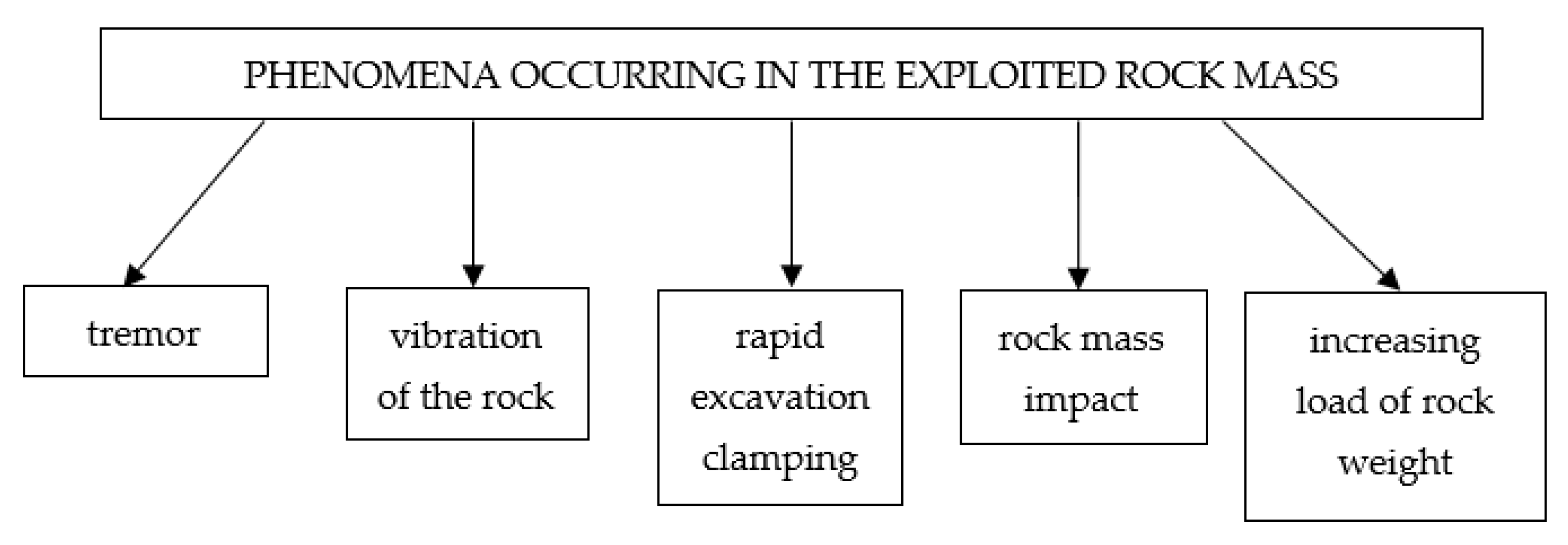
This impact may have a different character and be the result of various phenomena occurring in the rock mass [
5,
32,
33,
34,
35,
36]. A list of these phenomena and their effects on the support is shown in
Figure 2.
Phenomena occurring in the rock mass and their sequences are presented below and in
Figure 2 [
2,
3,
10,
30,
32,
34,
35,
36,
37,
38,
39].
Vibration of rock mass arises as a result of the dynamic impact of the rock mass, and its intensity, and thus the effects depend on the location of the epicentre and the geological structure of the rock centre.
Rapid clamping of the excavation is caused by settling of the roof. The size of settlement and its course in time varies depending on the type of seam and coal as well as the rate and method of exploitation.
Mass impact, a dynamic impact of the rock mass, occurs as a result of cracking of rocks around the excavation. The excavation is weighted with rock mass from deposits located above. The estimation of the mass size and its speed allows determining the energy with which the support is loaded as a result of a tremor.
Increasing load of rocks may occur in the case of roofs of very low strength or in which there is complete destruction of rocks. The load on the support during this process depends on the weight of the rock masses.
They are all caused by a violation of the balance in the rock mass due to mining activity.
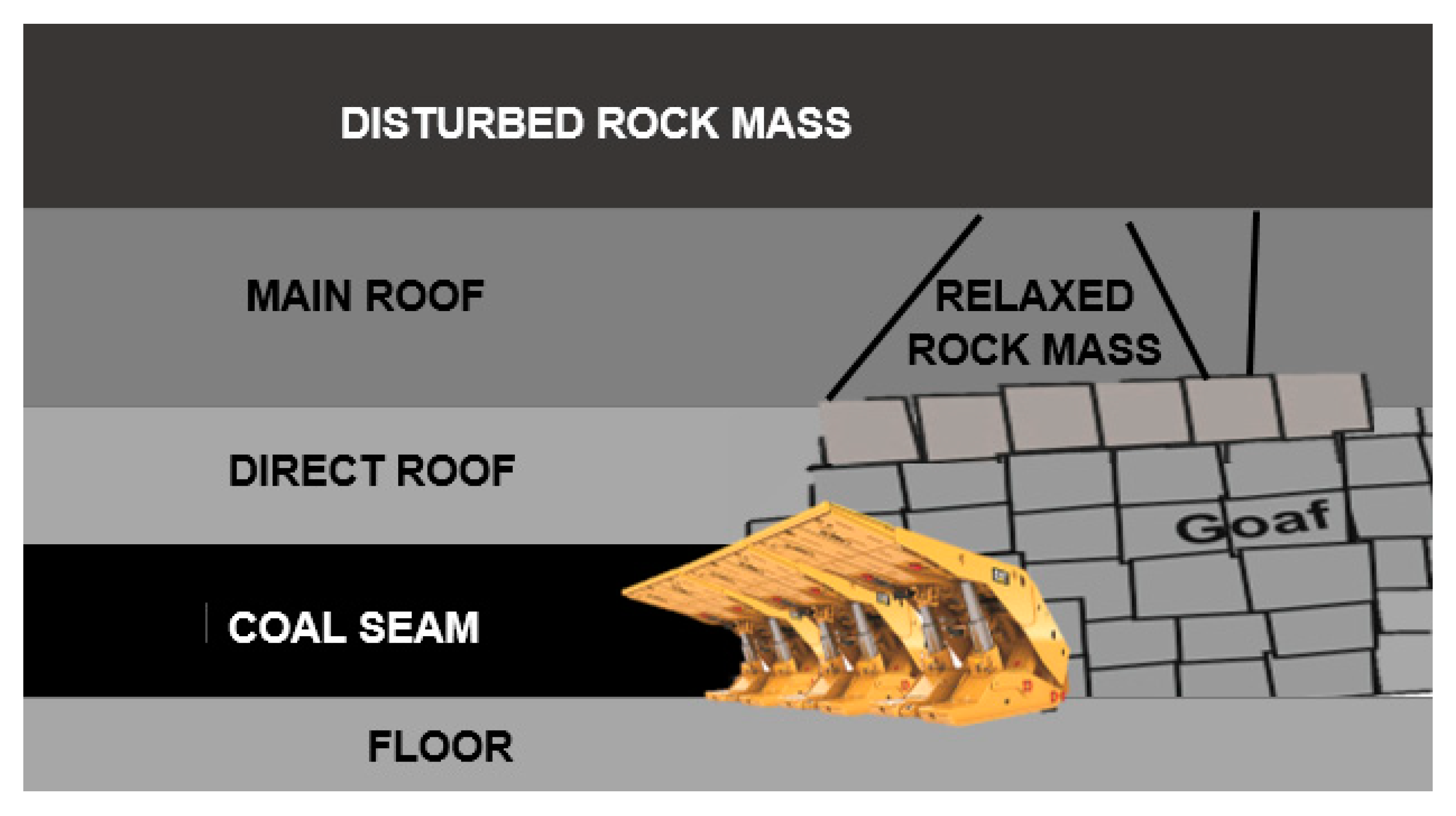
The general model of the rock mass, disturbed as a result of the executed mining excavation, is presented in
Figure 3.
This model in a simplified way presents phenomena that occur in the rock mass as a result of mining exploitation. The effect of this exploitation is primarily settling of rock layers lying above the exploited excavation. Settlement of layers leads to the development of deformation processes, which in the case of thick and durable layer, cause tremors. Settlement of thick sandstone layers in the adjacent layers causes them to crack. Consequently, the layers lose physical continuity but maintain geometric continuity thanks to mutual meshing of individual blocks. After exceeding the limit spread, the connected layers lose their load capacity and break down into individual blocks. This phenomenon is accompanied by an increase in the load impacting on the roof support. The course of this load depends on the nature of the phenomenon of crumbling the structure of these layers.
Most often, the course of such phenomena is dynamic. The resulting tremor releases energy that has its source both in the Earth’s gravitational field and geotectonic disturbances, as well as the concentration of stress around mining excavations and components of this concentration in the form of critical rock mass exertion. The effects of these tremors obviously impact on the support, however, the effects depend on many factors and can be very different.
They decide whether the rock mass is relaxed, in a state of tremor, or rock burst (phenomena defined by and recognized in the mining industry in Poland). The latter is particularly dangerous as it consists in dynamic relaxation of the rock mass, which results in damage to the support and mining excavations. Unfortunately, as a result of these phenomena, parts of the support section are very often damaged. Hydraulic cylinders and control systems are the elements that are damaged the most often.
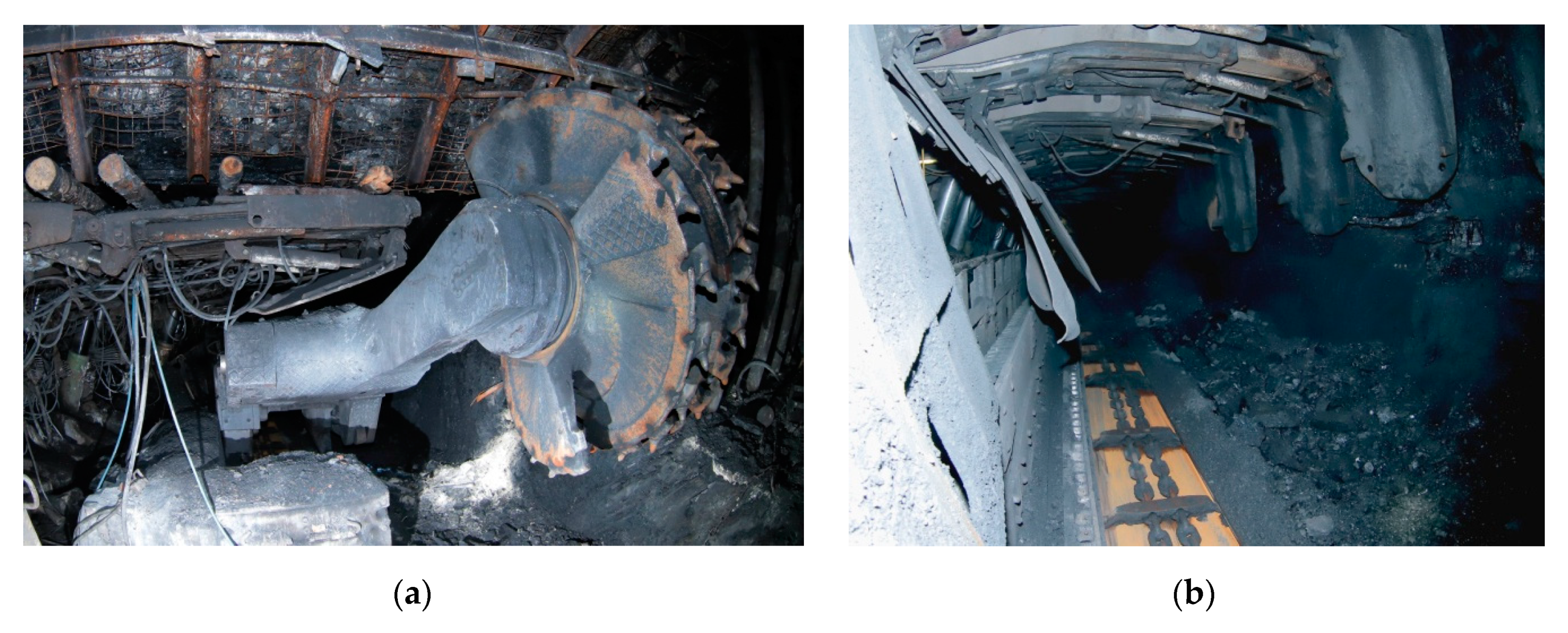
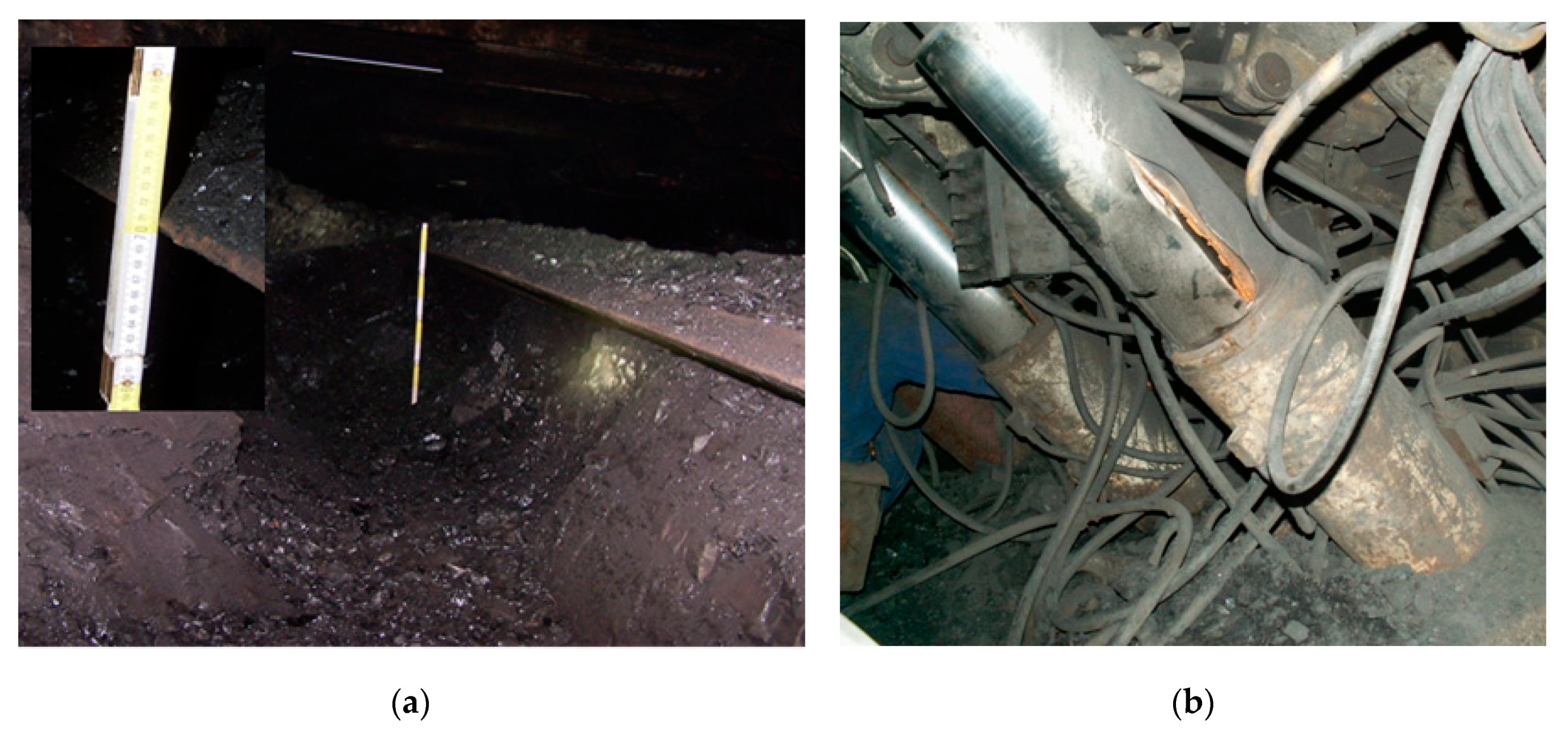
Examples of damages in the form of torn cylinders of hydraulic actuators are shown in
Figure 4b. Damage to the scraper conveyor (
Figure 4b) and to excavation (
Figure 4a) were the result of a rock burst that occurred in the area of this excavation.
This confirms that the loads acting on the mining support are the result of the impact of the rock mass whose stability was disturbed as a result of mining processes. The variety of loads resulting from this state affecting the support and the effects they cause depends on many factors. All mining and geological conditions of a given area must be properly analysed and defined prior to selecting a powered roof support. The results of such tests should be applied when selecting individual section components, particularly the control system and the safety system of the leg.
Preventing damages to legs and their elements and maintaining the functionality of the roof support requires appropriate systems protecting against overloads. It seems that this is currently the most desirable direction of research on the development of powered roof supports. An effective safety system will allow full use of the mechanical capabilities of the support, while protecting it against the effects of overloads resulting from the dynamic impact of the rock mass.
3. Tests of the Safety System Securing the Hydraulic Leg of a Powered Roof Support
Tests for powered supports are carried out for their individual components as well as for entire sections. They include mechanical and hydraulic systems as well as control systems. Tests are conducted in real conditions including test legs and in the form of model tests. There are also various ways of loading the tested elements and sections.
Taking into account the current state of knowledge, practical experience and requirements for powered roof supports, it can be stated that hydraulic legs are essential elements impacting on the level of effectiveness of the system. Proper control system and protection means against overloads creates opportunities to fully utilize the potential of the entire support (including individual sections) and to adapt to mining and geological conditions in which mining is carried out. The role of safety systems is also very important from an economic point of view. It should be emphasized that the powered roof support is the most expensive machine in the powered complex so it must be protected against possible damage and failure.
Taking into account the above considerations, the chapter presents the results of stand tests and model tests of the hydraulic system of the leg, with particular emphasis on the safety and control systems. Stand tests of the leg were carried out with its dynamic load and constant displacement on a fast sliding press.
The most dangerous phenomenon for the safe operation of the support and individual sections is a mining tremor. It lasts about 0.01–0.03 s and causes a short-term increase in the load of the powered roof support section [
30,
40]. If, as a result of tremors, the excavation or machinery are damaged, this event is classified as a rock burst. Tremors result in a very rapid increase in pressure in the working space of the leg. Damages to the leg caused by such a tremors can be prevented by installing a hydraulic safety valve in the leg. This valve must be resistant to overloads caused by dynamic loads that change over time and have an appropriate flow characteristic
Q = f(
p). Its operation should prevent the pressure in the leg from rising above the permissible value. In terms of safety of the hydraulic leg at dynamic loads, the valve is crucial as it protects the leg against damage [
20,
21,
41]. An example of the construction of a piston safety valve is shown in
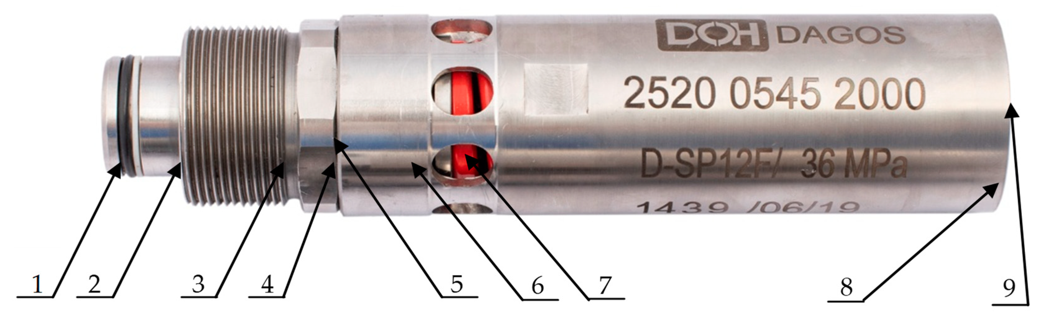
Figure 5.
The analysis of the design of this valve indicate that it is a hydraulic valve with a special design that allows opening and closing the flow in a very short time, while maintaining a very high flow. The safety valve is built into the hydraulic system to effectively protect the working space of the leg. It is usually a space under the piston for the first stage of the leg [
21,
41,
42,
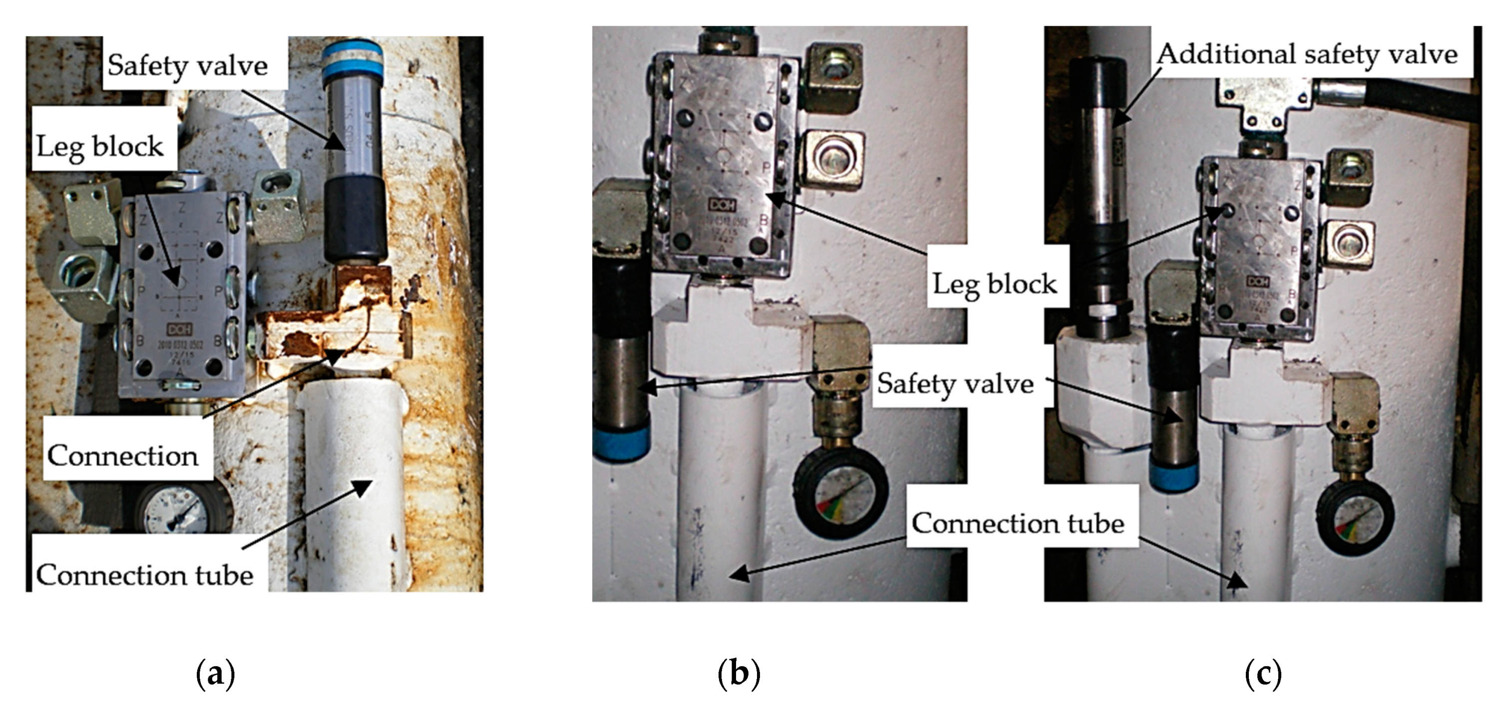
43]. Exemplary solutions of systems protecting hydraulic legs with liquid outlet through the safety valve outside the internal hydraulic system are shown in
Figure 6.
The role of the safety valve and the characteristics of its operation for the operational safety of the hydraulic leg and the entire support section are crucial. The valve and all additional accessories (
Figure 6) are designed to secure the entire hydraulic system of the powered roof support. The parameters of this valve also have a significant impact on the performance characteristics of individual legs and sections as well as the entire support. Therefore, special attention was paid to the selection and installation of safety valves during the testing of the leg safety system.
The hydraulic system and the system protecting the leg against overload are key components of the longwall system. Consequently, they must be thoroughly tested before they can be admitted to operate underground.
The purpose of stand tests is to determine the work characteristics of the leg for different types of load. Such tests should, as far as possible, reflect the real conditions in which the section with the tested leg will work. The research team conducted tests during which dynamic (impulse) load on the support and static load growth were mapped.
3.1. Dynamic Test of the Protection of the Hydraulic Leg
The dynamic tests of the hydraulic leg of the powered roof support along with the safety system were carried out at a drop weight tester [
8,
23,
40]. The leg was impacted with a free-falling impact mass [
40,
44,
45,
46,
47]. The leg was initially expanded in the frame of the tester by loading it with the mass of the traverse. This reflects the static load on the leg in a mine heading, while ensuring its stability during the test.
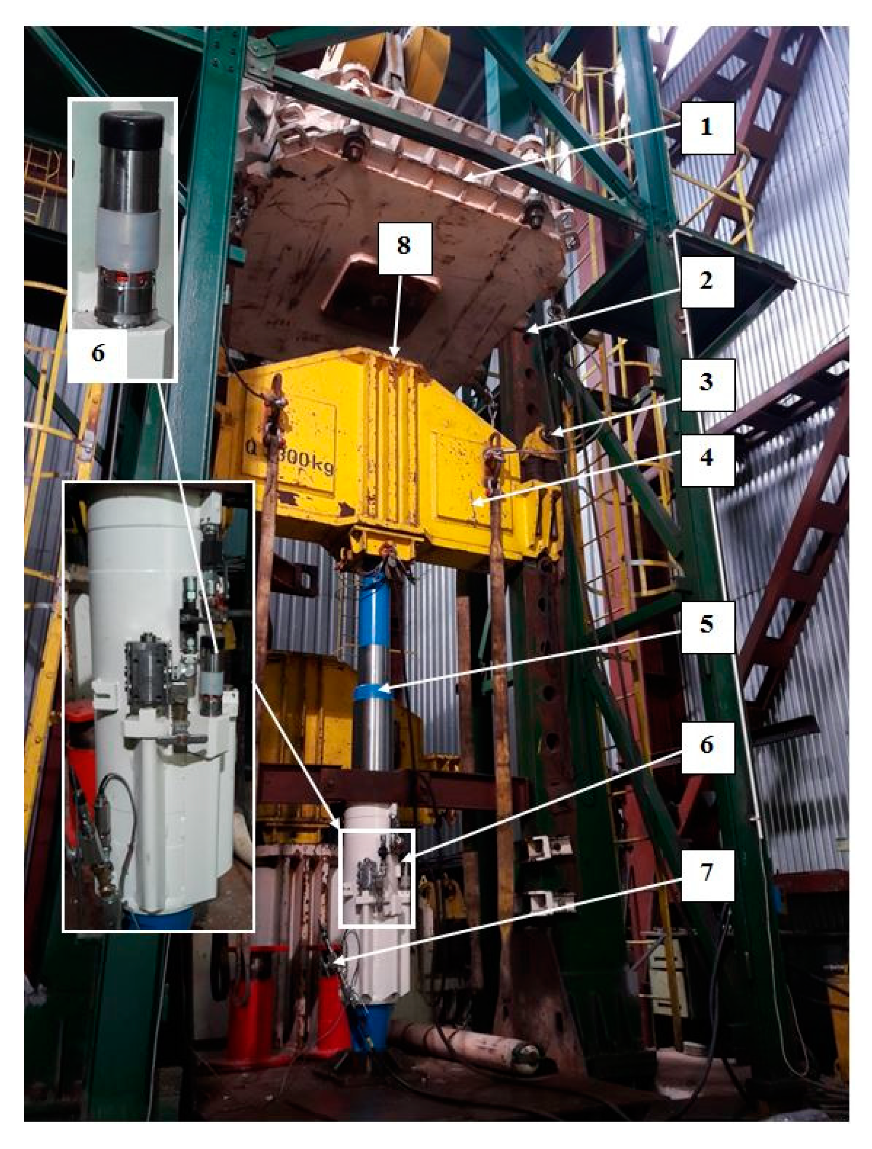
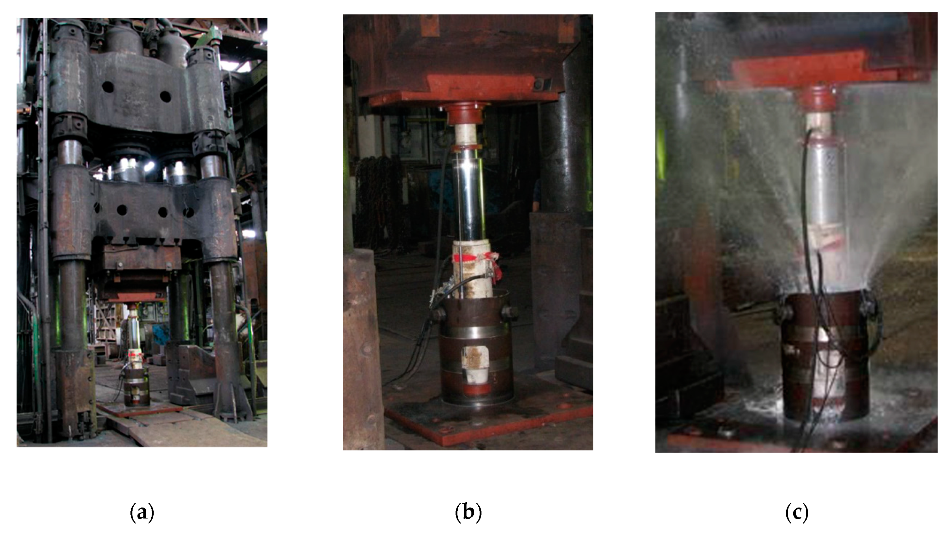
Figure 7 presents the test stand with its main elements marked.
The tested leg was equipped with a safety valve. Its purpose was to protect its working space against pressure increase caused by mass surges. As mentioned before, the mass load reflects the mass impact of the layers and tremor in actual underground conditions (
Figure 2). The main factors determining the effectiveness of the leg’s safety system are volume of liquid contained in the piston space of the leg, its mechanical properties, cylinder deformability, size and type of a discharge valve, as well as the way it is connected to the hydraulic system.
The course of forces in a dynamically loaded leg [
41,
45,
48] is determined as follows:
where
Fmax is maximum amplitude of force in oscillatory motion (N),
t is time (s),
is frequency of vibrations and
k is the elasticity constant of the leg, and
m is the mass of the leg, (kg).
The analysis of the relationship (1) indicates that the value of the modulus of elasticity directly affects the frequency of vibration of the leg, i.e., the elongation or reduction of the duration of the system response to dynamic load. Reducing the value of the modulus of elasticity results in a reduction of vibration pulsation, i.e., also the time of rise of the load. Reducing the rise time of the load is beneficial due to the work of the discharge (safety) valve connected to the hydraulic system of the leg. Reducing the elasticity also reduces the maximum load value. This means that the liquid contained in the core space, which is an additional absorber of impact energy, increases the leg’s resistance to dynamic loads.
The elasticity (
k), in addition to the volumetric modulus (
B), is influenced by factors such as the cross-sectional area of the liquid column (
Sc) and the column height (
Lc), as presented below:
where
B is volume modulus of elasticity,
Sc is cross-sectional area of the liquid column (m
2) and
Lc is height of the liquid column (m).
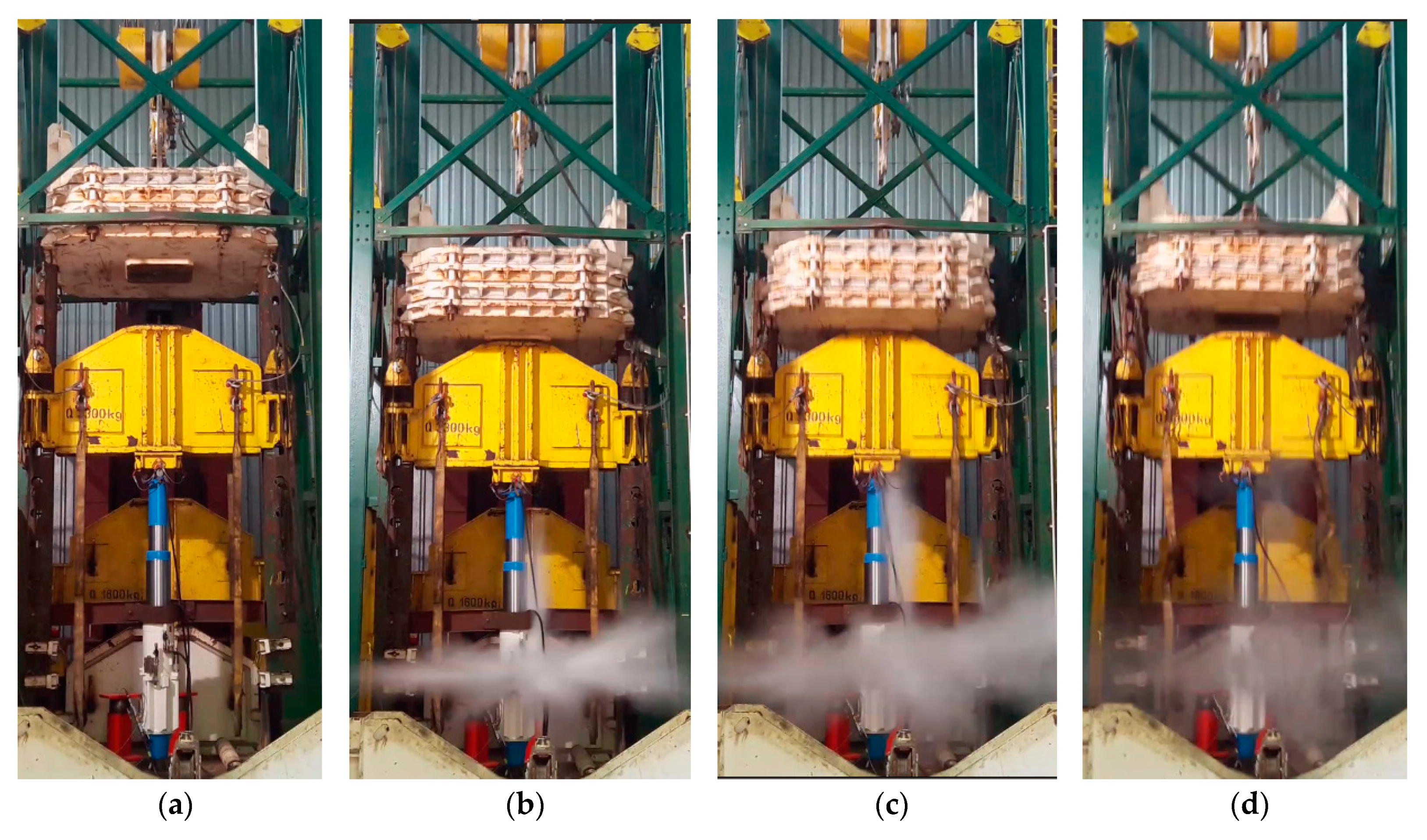
Stand tests were carried out on the leg which had been mounted and operated in a powered roof support in an active underground working. The method of loading the leg was based on loading it with the impact mass falling on the traverse that rested on the leg. The impact energy was determined on the basis of the impact mass and the height of its decrease. The tests were carried out for various impact energies by changing the height of the impact mass decrease. The purpose of the research was to determine the operating characteristics of the leg determining the change in pressure value in the leg’s piston space over time.
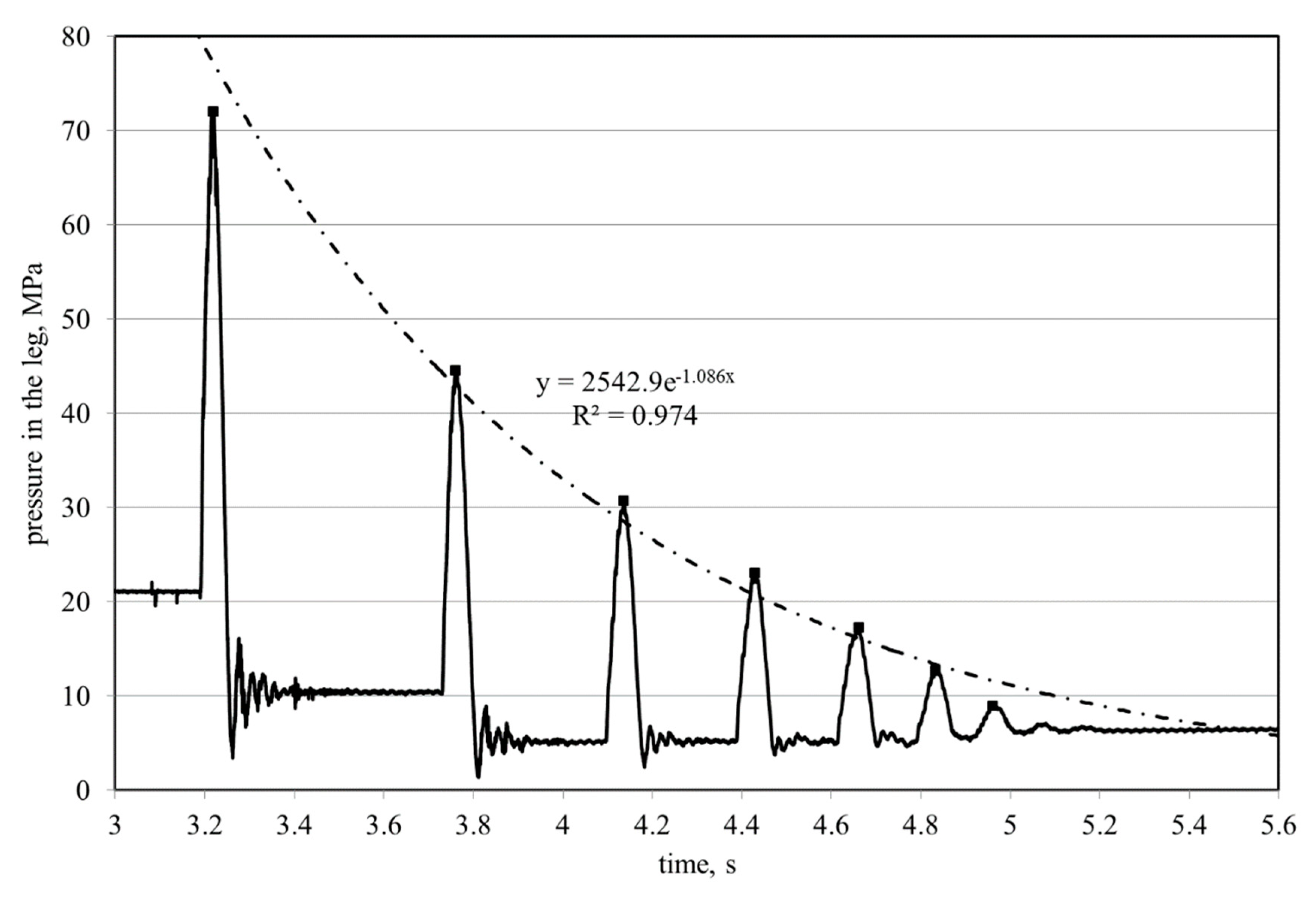
Figure 8 shows the four phases of the same test during which the safety valve was opened. The impact energy in the present case was 140.0 kJ. The characteristic determined for the tested leg is shown in
Figure 9. In the presented case a safety valve DN 19 with threaded end (M 45 × 2) was used. The crossbar weighted 3300 kg. The results of similar tests are presented in [
47], where the safety valve was attached with a Stecko connector DN 12, and the crossbar weighted 1800 kg. Both tests were carried out at different positions but with similar mass impact energy. Despite the visible similarity of the registered runs, the results obtained (especially in terms of maximum pressure values) are different. In addition, equations defining the trend lines of maximum pressure values recorded in the cylinder of the leg were also determined. The reduction of these values (damping process) most accurately describes the exponential equation, which is presented in the figure together with the value of the coefficient of determination (
R2).
The results clearly show that the impact energy was high enough to open the safety valve in the leg. Analysis of the obtained characteristics allows to determine the time of this opening and the maximum pressure in the leg in relation to the pressure of the safety valve setting. This, in turn, makes it possible to assess the quality and effectiveness of the valve used. The obtained results also indicate that the mass impact load is of a pulsating nature. Consequently, the leg is loaded several times. Its shortening, due to the occurrence of a slide (due to the outflow of liquid), causes it to become more yielded. This phenomenon is very beneficial. It sets a new state of balance between the rock mass and the support. It can be assumed that a correctly selected and functional safety valve protects the hydraulic system of the leg (and the leg itself) from overloading and improves the cooperation of the support with the rock mass. Therefore, these conclusions fully justify testing of a leg with protective systems under impact loads.
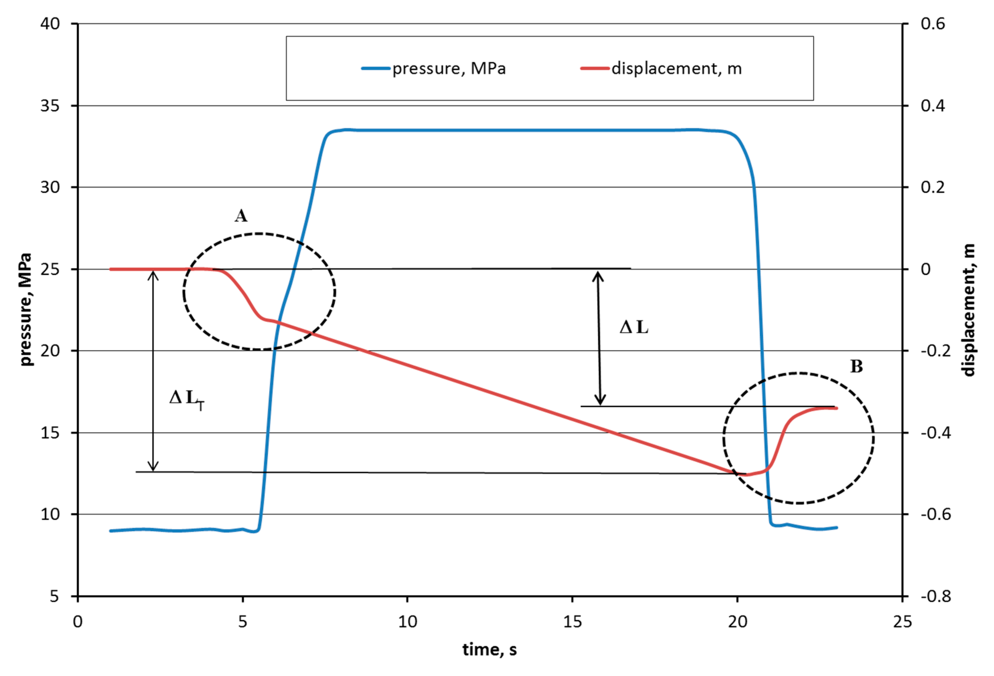
3.2. Tests of a Hydraulic Leg Loaded with Constant Displacement
A very common way of loading the support, and hence the leg, is the load resulting from the workings being clamped as a result of settling of the roof. The displacement of the roof occurs in this case at a certain speed and most often takes place in a uniform manner. In practice, this increases the pressure on the support and its displacement until it reaches a state of equilibrium. Mapping such a load condition of the support section or leg requires testing on a specialized press that allows clamping (displacement) at a constant speed. Such a machine is also known as a rapid hydraulic press.
The method of loading the leg on this press means that the pressure in the leg increases more slowly than under mass impact loads. In this case, inertial forces are therefore less important. However, exceeding the pressure value at which the safety valve is set causes its opening and outflow of liquid.
In reality, this method of loading can cause very negative effect, including serious damage. If, as a result of sliding (operation of safety valves), the pressure on the section is not reduced, the section may be damaged and the excavation will lose its functionality. Therefore, the safety valves should be set so as to slow down the rock mass which can sometimes be quite difficult to achieve.
The research team conducted tests using the rapid hydraulic press to determine how the hydraulic leg will behave under this type of load [
20,
21,
49]. The press was designed to carry out different types of tests. Here, the load resulting from the deformation of the roof in the longwall was successfully mapped.
The leg consists of four columns, connected to a traverse, which is guided along these columns. The tests were carried out for a hydraulic leg equipped with a Repair and Manufacturing Facility (RPF) type connection and a pressure relief valve (safety valve), DOH-DAGOS type. The slide in the press took place at a constant speed of about 0.1 ms
−1. When the leg was clamped, the leg pressure and the size of the slide were recorded. Time courses of these quantities determine the characteristics of the work of the leg. The testing station with the leg is shown in
Figure 10 and the waveforms obtained during the tests are presented in
Figure 11 [
20,
21,
49].
The results show that when the leg is loaded with a constant speed, the process of reaching the pressure limit at which the safety valve opens depends on the sliding speed of the press. This, in turn, causes that a valve overload is smaller than in the case of the impact load of a free-falling mass (
Figure 9). It can also be seen that the leg slide is stable and depends on the time the load operates. In practice, this can lead to the complete sliding of the leg and loss of stability of the section and the entire support. Undoubtedly, the analysed load condition and its effects occur very often in actual workings and pose a serious threat to stability of the support system. The results obtained indicate the need for further testing of the legs and entire sections at a constant speed of slide in order to optimally select the parameters of the leg’s safety system. In this case, it seems reasonable to use sequential safety valves that would allow an increase in load capacity as the size of the leg’s slide.
3.3. Numerical Analysis of Flows in the Leg’s Protection System
In addition to stand tests, in recent years model tests have been used increasingly to analyse many physical and chemical phenomena. Also in the field of mining support testing, these tests are increasingly used. Their undoubted advantage is the possibility of analysing many phenomena, the study of which in real or stationary conditions is practically impossible or very expensive. Also the possibility of multi-variant analyses in spatial systems, taking into account time and variability of other parameters, means that they are used more and more often. In the case of powered supports, these tests can be used primarily for mechanical and flow analyses. Tests of hydraulic flows in legs are important when adapting the circuits to changing mining and geological conditions.
It can be assumed that in the process of sustainable development of powered supports and methods of testing them, model tests should be one of the basic methods used for such types of analyses.
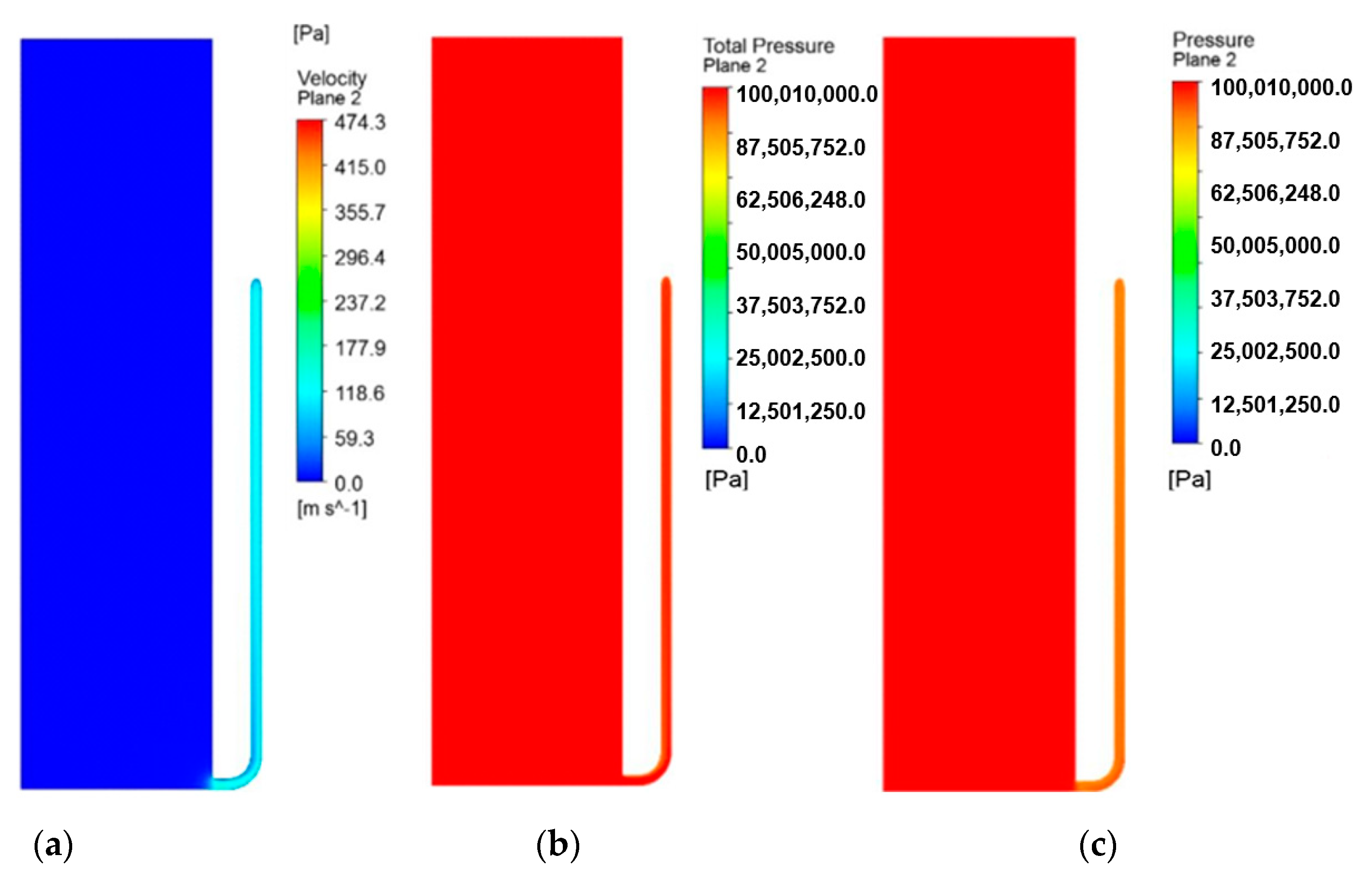
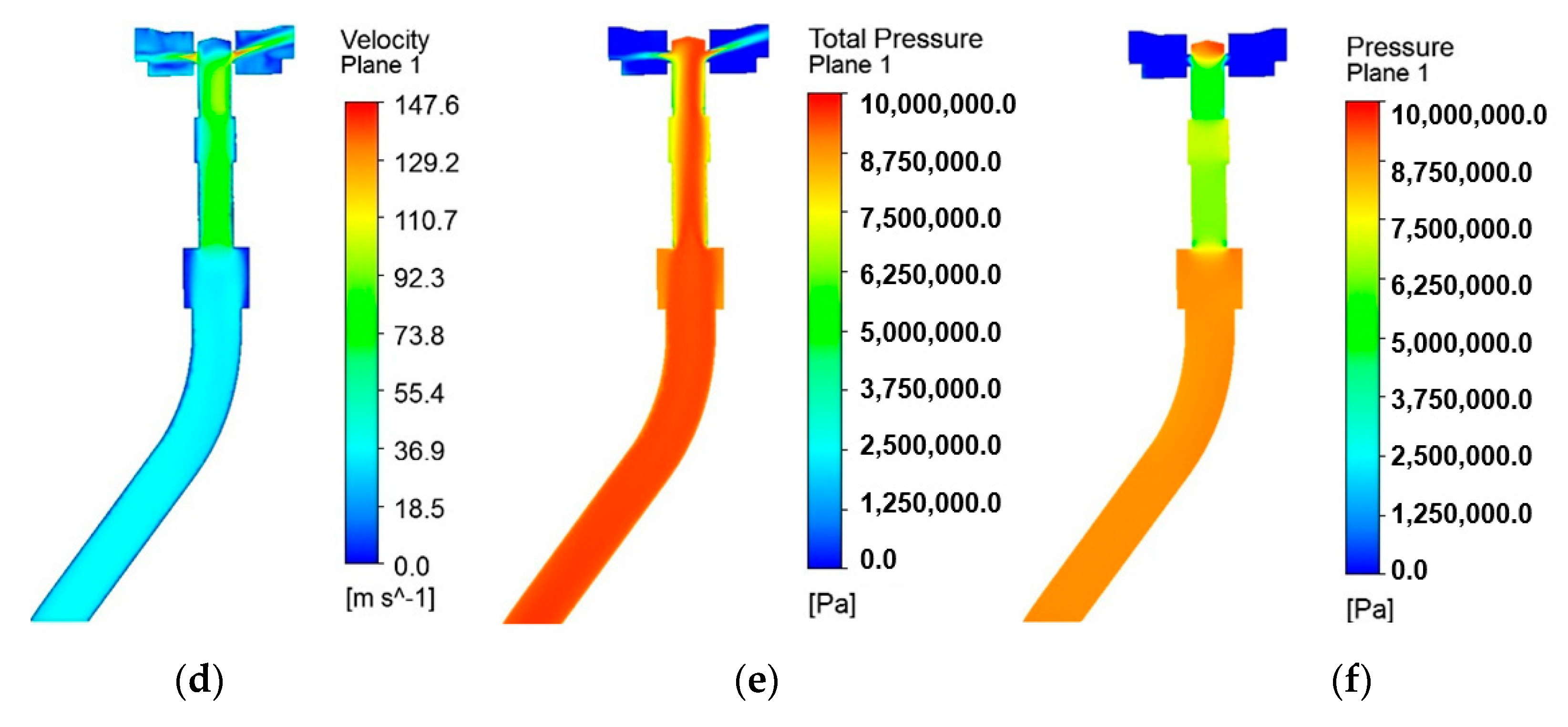
The paper presents an example of the use of numerical fluid mechanics to analyse the flow of hydraulic fluid in a hydraulic leg and the connection supplying liquid to the safety valve at static load on the leg. The results of the analysis of rate and pressure distribution at the connections support the safe operation of the system.
The advantages of model research can be clearly seen in this type of analysis. They make it possible to trace the tested parameters practically at every point of the tested object. Acquiring such knowledge from other studies is impossible. It is also obvious that in the case of model tests, the reliability of the results obtained depends on the accuracy of the mapping of the tested object and the adopted boundary conditions. The results obtained can significantly enrich knowledge and explain the essence of the phenomena for example when analysing the flow of liquid in a hydraulic leg [
20,
41]. The results obtained and presented in
Figure 12 clearly show the velocity and pressure distributions, especially at the connections of this leg.
It should be emphasized that the determination of flows in the working systems of a powered roof support can be the basis for qualifying it for work in conditions of tremors and other rock mass impacts.
It is obvious that the possibilities of model testing, especially in the field of flow testing, are very large and should be widely used for testing roof supports. The use of these tests makes it possible to determine the performance characteristics of a hydraulic system, depending on many factors. One of them is the geometry of the connection’s flow channels.
Therefore, in the case of powered roof supports testing, it is also reasonable to use model tests. It is important to remember that the quality of the results of model tests depend largely on the accuracy of the developed model and the correctness of the adopted boundary conditions.
However, in many cases they can be verified and validated by such methods as measuring the pressure value at selected points of the hydraulic system.
Therefore, it is fully justified to state that in the process of research on the sustainable development of the powered roof support intended for operation in variable mining and geological conditions, model tests may constitute a very important and valuable part of these tests.
3.4. Research on the Development of Electro-hydraulic Control of a Powered Roof Support
In addition to mechanical and hydraulic systems, the most important system in support, in many cases, determining the effectiveness of its work is the control system. Therefore, it is obvious that scientific research on this system must be accelerated. The pursuit of unmanned operation (or with a minimal presence of people in the longwall) and the increasing use of digital data to support the roof support and the entire complex mean that the demand for more and more intelligent control systems increases.
The current level of technology does not allow for the complete elimination of miners from the longwall. This is also not to be expected in the coming years. This is mainly the result of not fully definable conditions in how underground mining is conducted. However, this does not limit the development of control systems, for which the requirements are increasing and will grow. The basic direction are works whose effect is relocation (removal) of as many activities as possible outside the mining longwall [
50,
51,
52,
53]. In this area, the role and importance of control systems is key.
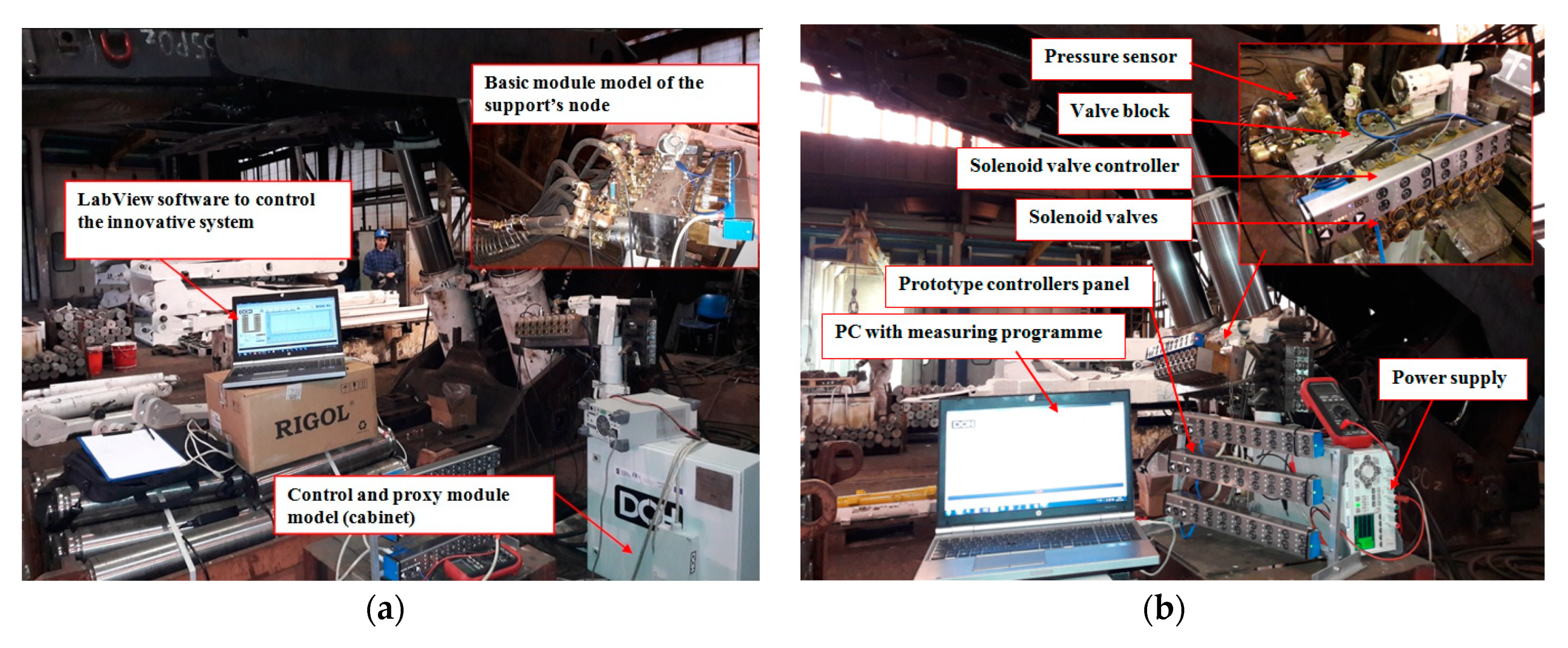
Research in this area mainly includes work on the development of electro-hydraulic control. A special testing station was designed, based on a virtual controller, to facilitate tests of new control systems. It determines a number of control system parameters. Its main purpose is to determine static and dynamic performance characteristics of control hydraulics components. The station also tests systems protecting hydraulic cylinders against overload.
The station is mobile and can be used to conduct research in a variety of environments, which significantly extends the scope of research. It enables testing of control elements and visualization of the work parameters of a powered roof support.
Figure 13 shows the station with its components and elements marked [
54,
55].
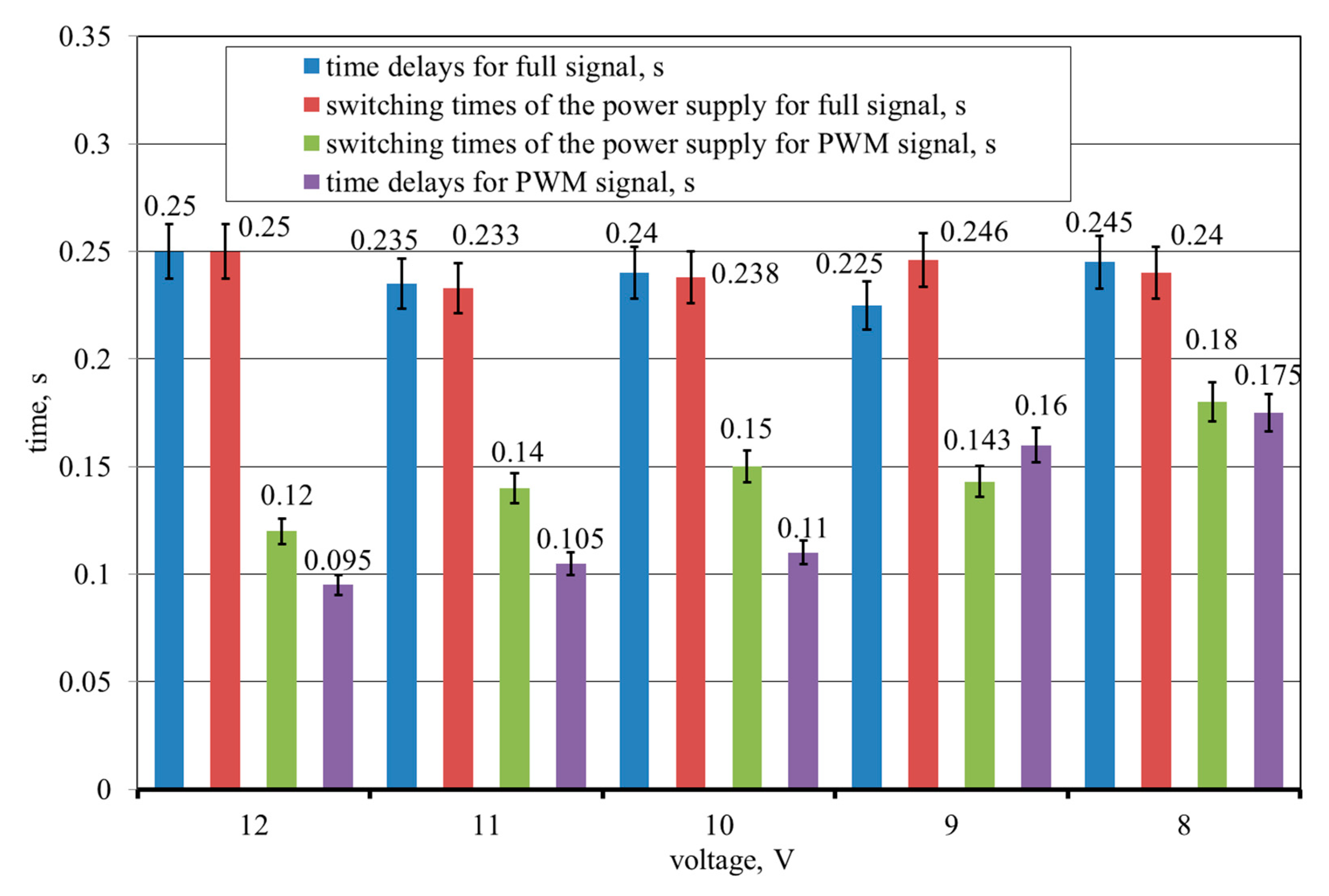
The scope of research carried out using the developed system is very wide. One of the problems was to determine the times for implementing the basic functions of the support. It mainly concerned the spreading and withdrawing of sections (extensions/slides of hydraulic legs mounted between floor bases and canopies). Measurements in this area included determining the time of switching on the PWM signal and full signal supply for the basic functions performed by the roof support. The operating parameters of the control system obtained for individual phases of the section operation are shown in
Figure 14 [
54,
55]. An analysis of measurement uncertainty was also carried out for these results.
The obtained results clearly indicate that the tested electro-hydraulic system has very short response times, which ensures fast and reliable performance of the tasks that the roof support has to perform. These results also enable comparative analysis of the control systems and their components as well as sensitivity analysis. This, in turn, enables the appropriate selection of control parameters for specific mining and geological conditions in which exploitation is to be carried out. These conditions are the basis for forecasting the load states that the mining support may be subjected to.
It can therefore be assumed that the use of virtual testing techniques for already used systems as well as new solutions and prototypes creates great possibilities for their evaluation. At the same time, the conditions to which these systems will be subject in real conditions are impossible to achieve. For this reason, the developed system and the entire test stand has great research potential. It is also an example of using modern IT systems in the mining industry. Its versatility should also be emphasized as it makes it possible to apply testing hydraulic systems in other industries.
Undoubtedly, this enables conducting multi-variant tests of hydraulic systems in a scope that would be impossible to carry out or would be very expensive and time consuming in other conditions.
4. The Concept of a Powered Roof Support Testing Procedure Designed to Adapt it to the Operating Conditions
The analysis of loads to which the mining support may be subjected during operation in underground longwall excavations as a result of the deformation impact of the rock mass (
Section 2) indicates that in order to fulfil its functions, it must be properly designed, constructed and operated. Therefore, it is necessary to conduct tests of elements, sub-assemblies and entire sections of this support as much as possible. In this regard, it is necessary to use all available research methods. This is due to the fact that the role and importance of support in the mining process is very large, and in particular concerns the safety of people.
It is therefore reasonable to develop a comprehensive procedure for testing the conditions in which the support and its sub-assemblies and components will be operated in terms of adaptation to these conditions. This procedure, apart from various test methods to which the elements and sub-assemblies of the support section should be subjected, also takes into account legal conditions in the scope of approval, testing and quality control of the support [
56,
57,
58,
59,
60,
61]. This is a key element of the presented concept as it significantly interferes with manufacturers of the support. The most important part of this procedure is to determine the research area that will be used to implement it. It is about research methods and tools that will be included in it.
Reliable research results should be the basis for development of legal conditions. New directives and standards, and thus also certificates, should take into account, as soon as possible, the results of testing the supports and all the data and knowledge resulting from the use of the systems. They should also flexibly relate to changing operating conditions, which was included as the third pillar of the developed concept.
The whole concept is based on three pillars: research, real conditions (underground mines), and the legal regulations related to the production of supports. This comprehensive approach to analysing the state of safety and the requirements to be met by the support before it is put into service creates the opportunity to improve the safety and efficiency of the operation process.
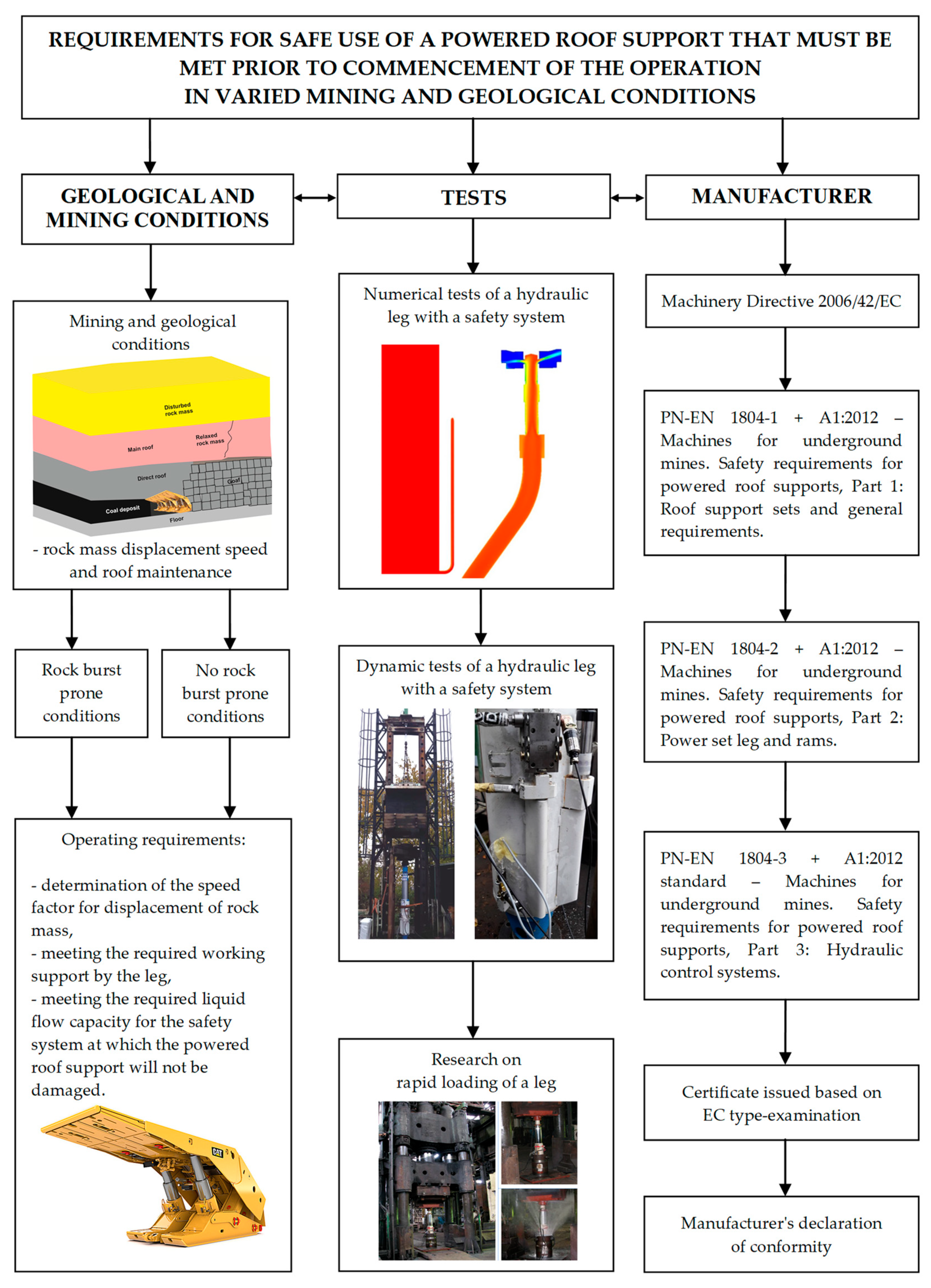
A block diagram of the developed concept of a powered roof support approval procedure based on required safety demands is presented in
Figure 15. As already mentioned, this procedure takes into account the mining and geological conditions in which the system will be used, which determines the method of its loading, the methods of testing safety systems designed for legs and support sections (discussed in the
Section 3) as well as legal conditions determining the approval, discussed in
Section 2.
It can be assumed that the presented concept covers all the most important areas in terms of safety and efficient operation of the roof support.
The conditions in which the mining roof support operates are random, therefore the developed procedure should be used for each new mining longwall separately. Each time the scope of its use should be tailored to the projected mining and geological conditions of a given area. The identification of potential loads and requirements for the maintenance of the excavation roof should be the basis for further activities and calculations. Possible structural changes and other systems should be preceded by a thorough assessment of these conditions.
The presented procedure is open and, depending on the needs and possibilities, can be supplemented with new information about the state of the rock mass, new research methods, and legal conditions.
5. Conclusions
The key component of currently used high-performance systems for mining underground coal deposits is the powered roof support. Its reliable and effective work in the field of securing mine workings enables safe and effective operation of the mining process. Changing mining and geological conditions of the mining area results in many requirements that must be meet by the roof support. These requirements increase with deteriorating environmental conditions, which is obvious when the depth of mining activities increase. Therefore, research and tests are carried out to adapt the support to such unpredictable mining conditions.
The roof support requires continuous improving. This especially refers to its individual sub-assemblies and elements. The concept of a new procedure for approving the support to work in specific mining and geological conditions presented in the paper perfectly fits the improvement process. This procedure is based on three pillars. The first includes the identification of mining and geological conditions in which mining will be carried out. This should enable forecasting of the conditions of load impacting on the roof support during mining operation. The second pillar includes comprehensive testing of sub-assemblies, systems and components of the roof support section in relation to projected loads. The purpose of these tests is to assess the safe operation of the roof support in varied conditions. The paper refers to impact mass load and load resulting from permanent displacement. The research team developed stand test methods to analyse both types of load. Model research, which was included in the proposed set of support test methods, is also very important. The use of mechanical analyses, only briefly mentioned in the paper, as well as analyses using numerical fluid mechanics (CFD), should constantly increase.
The last pillar of the developed concept are legal conditions that must keep up with the changes taking place in previously discussed pillars. These conditions determine the practical application of the results of identification of potential loads and solutions in section systems designed to meet these loads. Undoubtedly, these acts and the approach to the authorization of mining support for mining requires a separate study and discussion. It is crucial to include the latest research achievements and practical experience in the newly developed acts.
The hydraulic control systems in the support section also have very important significance as it was presented in the paper. The developed systems for testing them create great opportunities to develop and implement new effective solutions that limit the work of people in hazardous areas.
Another element that has an enormous impact on the safety of the mining operation, the roof support and the whole system is a safety valve. Its significance and results of conducted research are presented in the paper (
Section 3). Its value in terms of safe and efficient operation of the roof support was numerously emphasized in the paper. Such valves should effectively protect the sections against overloads and damage. Therefore, safety valves were subjected to model and stand tests. Tests in an actual underground area will be conducted in the near future.
The results of presented analysis and tests show that prior to admitting the powered support to be installed and operate, a thorough analysis of the requirements for its safe use should be conducted. Such analysis should cover the entire support section, but in particular its safety system. The procedure proposed and presented in
Figure 15 enables a full assessment of the possibilities of the support section and safety system for the expected conditions of its operation.
The research team managed to develop a method that is undoubtedly a new and original approach to testing and controlling the condition of the support section. It also facilitates the selection of a support that will operate properly in given changing mining and geological conditions. The presented methodology and obtained test results proves that the main objective has been achieved. The authors, thanks to appropriate research methods and tools, designed an original way of testing and controlling the condition of the section and a method for selection for various mining and geological conditions.
The open nature of this procedure is its best advantage thanks to which the procedure can be modified depending on the conditions, requirements and needs, as well as research capabilities. This applies to both manufacturers and users of the roof support. In particular, the responsible approach of contractors ordering the roof support, its potential users. Their task is to select a system that will match the conditions prevailing in a given underground area. In this case, first of all, the safety of the miners and the safety of the roof support must be taken into account. The support is the most expensive machine of the powered roof support complex and its safe use impacts the economic efficiency of the entire mining process.


