Article

CFD Analysis of Falling Film Hydrodynamics for a Lithium Bromide (LiBr) Solution over a Horizontal Tube

1
Division of Sustainable Development (DSD), College of Science & Engineering (CSE), Hamad Bin Khalifa University (HBKU), Education City, Doha 34110, Qatar
2
Qatar Environment and Energy Research Institute (QEERI), Hamad Bin Khalifa University (HBKU), Education City, Doha 34110, Qatar
*
Author to whom correspondence should be addressed.
Energies 2020, 13(2), 307; https://doi.org/10.3390/en13020307
Submission received: 30 November 2019 / Revised: 24 December 2019 / Accepted: 6 January 2020 / Published: 8 January 2020
(This article belongs to the Special Issue Fluid Flow and Heat Transfer Ⅱ)

Abstract

:
Falling film evaporators are used in applications where high heat transfer coefficients are required for low liquid load and temperature difference. One such application is the lithium bromide (LiBr)-based absorber and generator. The concentration of the aqueous LiBr solution changes within the absorber and generator because of evaporation and vapor absorption. This causes the thermophysical properties to differ and affects the film distribution, heat, and mass transfer mechanisms. For thermal performance improvement of LiBr-based falling film evaporators, in-depth analysis at the micro level is required for film distribution and hydrodynamics. In this work, a 2D numerical model was constructed using the commercial CFD software Ansys Fluent v18.0. The influence of the liquid load corresponding to droplet and jet mode, and the concentration, on film hydrodynamics was examined. It was found that the jet mode was more stable at a higher concentration of 0.65 with ±0.5% variation compared to lower concentrations. The recirculation was stronger at a low concentration of 0.45 and existed until the angular position (θ) = 10°, whereas at 0.65 concentration it diminished after θ = 5°. The improved heat transfer is expected at lower concentrations due to lower film thickness and thermal resistance, more recirculation, and a higher velocity field.

1. Introduction

Falling film exchangers are commonly employed in ammonia (NH3)- and lithium bromide (LiBr)-based absorption refrigeration systems [1,2,3,4,5,6]. In falling film exchangers, a thin layer of liquid film is formed around the tube and heat is transferred to/from the fluid flowing inside the tube. The heat and mass transfer coefficients strongly depend on the film hydrodynamics. Extensive experimental, analytical, and numerical works were performed to describe the falling film flow on bare and enhanced tubes [7,8]. The falling film characterization comprises of (a) film thickness, (b) wave formation, (c) wettability, (d) flow development regions, such as stagnation, (e) impingement, (f) developing, developed detachment, and necking zones, (g) flow modes, such as droplet, jet, and sheet, and (h) flow regimes, which include laminar, wavy laminar, and turbulent [7,9,10,11,12,13].
The falling film modes were experimentally distinguished: droplet, droplet-jet, jet, jet-sheet, and sheet modes. Researchers have developed empirical correlations based on films’ Reynolds number Ref and modified Galileo number Ga for flow mode recognition and transition [14,15,16,17]. The correlations developed by Roques et al. [16] are as follows:
Droplet to droplet-jet mode:
R e f = 0.0417 G a 0.3278 .
Droplet-jet to jet mode:
R e f = 0.0683 G a 0.3204 .
Jet to jet-sheet mode:
R e f = 0.8553 G a 0.2483 .
Jet-sheet to sheet mode:
R e f = 1.068 G a 0.2563 .
Ref and Ga are defined as:
R e f = 4 Γ 1 / 2 μ
G a = ρ σ 3 μ 4 g ,
where Γ1/2 represents the liquid load on one side of the tube, μ is the viscosity, g is the acceleration due to gravity, ρ is the density, and σ is the surface tension. In 1916, Nusselt established the film thickness δ correlation as a function of angular position θ, liquid load Γ1/2, and thermophysical properties [18]. The Nusselt solution, as shown in Equation (7), is widely used for thickness estimation and comparison purposes [9,19,20,21]:
δ = 3 μ l Γ 1 / 2 ρ l ( ρ l ρ g ) g s i n θ 3 .
Rogers and Goindi [22] measured the film thickness on an aluminum tube of 132 mm outer tube diameter D at three different angular positions, θ = 45°, 90°, and 135°. They found a 30% deviation on averaged when compared with Equation (7). Gstoehl et al. [23] applied the laser method to analyze the film thickness around the tube. The film thicknesses θ = 22°–62° and 112°–152° on a 19.05-mm copper tube were recorded for different intertube spacing s. They concluded that Equation (7) predicts the film thickness well for the upper region (θ = 0°–90°), but overestimates the thickness for the lower region (θ > 90°). Hou et al. [24] conducted experiments to measure film thickness using a displacement micrometer from θ = 15°–165° for D = 20–32 mm, s = 10–40 mm, and Ref = 150–800. They reached a similar conclusion, that Equation (7) overestimates the film thickness in the lower portion, and proposed a modified version of Equation (7) by incorporating intertube spacing in the tube diameter ratio (s/D). In addition, it was observed that the minimum film thickness lies in the range of 90°–110° instead of at a fixed location, i.e., θ = 90° as per Equation (7). Chen et al. [25] used the laser technique to capture film thickness in the longitudinal and circumferential directions. In their findings, the maximum film thickness was found to be at the crest location, where it was twice the minimum film thickness in the axial direction. Furthermore, higher film thickness for seawater was recorded as compared to water.
Since there are limitations in experimental procedures covering the entire parameters and capturing other details such as operating conditions, velocity, and temperature profiles within the film, computational fluid dynamics (CFD) has become an important tool for in-depth analysis to design optimal conditions for various applications. Tahir et al. [11] analyzed the liquid load distribution for each column and concluded that the triangular pitch configuration exhibits more maldistribution than a square pitch arrangement. Ji et al. [19] performed CFD simulations by implementing a volume of fluid (VOF) model to track the liquid/gas interface, with LiBr solution as the working fluid. They found the minimum thickness near 120°, so adjusted Equation (7) by replacing sin(θ) with sin(3/4 θ), such that it predicts the minimum thickness at 120°. Lin et al. [26] performed experiments and numerical calculations for a three-dimensional geometry, to examine the film distribution. They validated their VOF model with the experimental data and observed the minimum thickness to lie in the valley area, in which the heat transfer performance was found to poor. Wang et al. [27] also studied film thickness numerically, with a three-dimensional geometry of two 25.4-mm diameter tubes. They found that the minimum film thickness location depends on both the angular position and the axial displacement. Based on their CFD results, they proposed a film thickness correlation similar to Hou et al. [24], but with different parameters for three sections, namely impingement, transition, and departure regions. Hosseinnia et al. [20] carried out a numerical analysis for mass transfer mechanism in the LiBr-based absorber. The VOF model and h-refinement (a mesh adaptation technique) were implemented in order to solve conservation of mass, momentum, and energy equations. Their analysis showed that the mass transfer mechanism is greatly affected by the flow mode, as the absorption rate was decreased more than 10-fold when the flow mode was changed from droplet to jet. For this reason, most of the absorber operates under droplet, droplet-jet, and modes or low liquid load [9,20].
The film distribution around the tube can be divided into stagnation, impingement, developing, developed, detachment, and necking regions. The majority of the heat and mass transfer takes place in the first three regions [9], thus the film distribution affects the heat and mass transfer mechanisms. In this study, a 2D CFD model for an aqueous LiBr solution falling over a horizontal tube was modeled, which is used in the refrigeration and multi-effect desalination industries [28,29,30,31].The LiBr concentration changes in an absorber and generator due to vapor absorption and evaporation. As the concentration varies, the thermophysical properties differ and alter the magnitude of forces and hence the film hydrodynamics. The influence of LiBr concentration on the film hydrodynamics and conduction thermal resistance (which is often neglected) is lacking in the literature. Therefore, the effects of LiBr concentration, with corresponding liquid loads for droplet and jet mode, on film distribution were analyzed. First, the CFD model was validated using experimental data from the literature. Then, the transient behavior of falling film, film thickness distribution, average film thickness, and residence time were quantified and discussed. Afterwards, the tangential and normal velocities distribution for impingement and developing regions for low and high LiBr concentrations C were examined.

2. Problem Statement

In order to characterize the film distribution, one 25.4-mm tube was selected with an impingement height hi of 5 mm, as shown in Figure 1. The domain was equipped with a 2-mm orifice at the top of the tube. The width of the domain was 33 mm; since the nature of the problem is symmetric, only half of the domain is selected for CFD calculations. The aqueous LiBr solution is in the liquid phase and water vapors are considered as the gaseous phase. Two LiBr concentrations are chosen as per the common working range, i.e., low concentration C = 0.45 and high concentration C = 0.65. The thermophysical properties of the liquid and gaseous phases were evaluated as per [32] at 30 °C (the lower working temperature of the absorber [33]), as shown in Table 1.

3. CFD Model

For numerical model simplification, it is assumed that the flow is laminar for all cases. There is no fluid spreading in the z-direction. The thermophysical properties are constant throughout the distribution. There is no heat and mass transfer (adiabatic condition). The flow is symmetric along the y-axis. There is no vapor flow, and the wall adhesion contact angle θw is 0° (purely hydrophilic) to ensure the complete wetting of the tube [34].

3.1. Conservation Equations

The mass and momentum balances can be found by continuity and Navier‒Stokes equations, as shown below:
ρ t +   · ( ρ V ) = 0
( ρ V ) t +   · ( ρ V V ) = P + · ( τ = ) + ρ g + F v o l ,
where V is the velocity, t is time, P is the pressure, τ is the tensor, and Fvol is the volumetric force.

3.2. Volume of Fluid Model (VOF) Model

In falling film evaporators, the liquid and gaseous phases are separated by distinct boundaries. Hirt and Nichols developed a multiphase model named the volume of fluid (VOF) model to accurately capture the liquid phase interface [35]. The VOF model has been widely implemented in many applications such as bubble dynamics, reactors, falling films, capillary flows, flashing, and splashing in tanks to numerically distinguish the liquid/gas interface [36,37,38,39,40]. They modified the continuity equation as in Equation (8) by introducing void fraction α to solve the mass balance for both phase separately.
( α i ρ i ) t +   · ( α i ρ i V i ) = 0   ( i = g   o r   l )
The subscripts g and l represent gaseous and liquid phases, respectively. The density and viscosity are evaluated on the basis of the void fraction.
ρ = α l ρ l + ( 1 α l ) ρ g
μ = α l μ l + ( 1 α l ) μ g ,
where α is the void/volume fraction representing how much liquid is present in a liquid‒gas mixture. The liquid void fractions αg and αl are defined as follows:
α g = 1 α l .

3.3. Continuum Surface Force (CSF) Model

Brackbill et al. [41] developed a continuum surface force (CSF) model as shown in Equation (14) to calculate the volumetric force Fvol. The CSF model improves the characterization of the liquid‒gas interface by accommodating surface tension σ effects:
F v o l = σ K α l [   ρ 1 2 ( ρ l + ρ g ) ] .
The surface curvature K is computed by gradient of surface unit normal vector n ^ :
K = · n ^ .

3.4. Operating and Boundary Conditions

For the boundary conditions, (a) a mass inlet for liquid entrance is selected at the top, (b) a velocity inlet with 0 m/s is provided for water vapors, (c) a wall is selected for a tube with a zero contact angle, (d) a pressure outlet is for the outlet at the bottom, and (e) a symmetric boundary condition is chosen for the rest, as shown in Figure 1. The mass flow inlet varied from 0.01 to 0.5 kg/(m·s), with 0.02 kg/(m·s) intervals for both C = 0.45 and 0.65 concentrations, corresponding to droplet, droplet-jet, and jet mode. The films Reynolds number Ref and flow modes for each case are listed in Table 2. The gravity is acting in the negative y-direction with a value of 9.81 m/s2.

3.5. Methodology

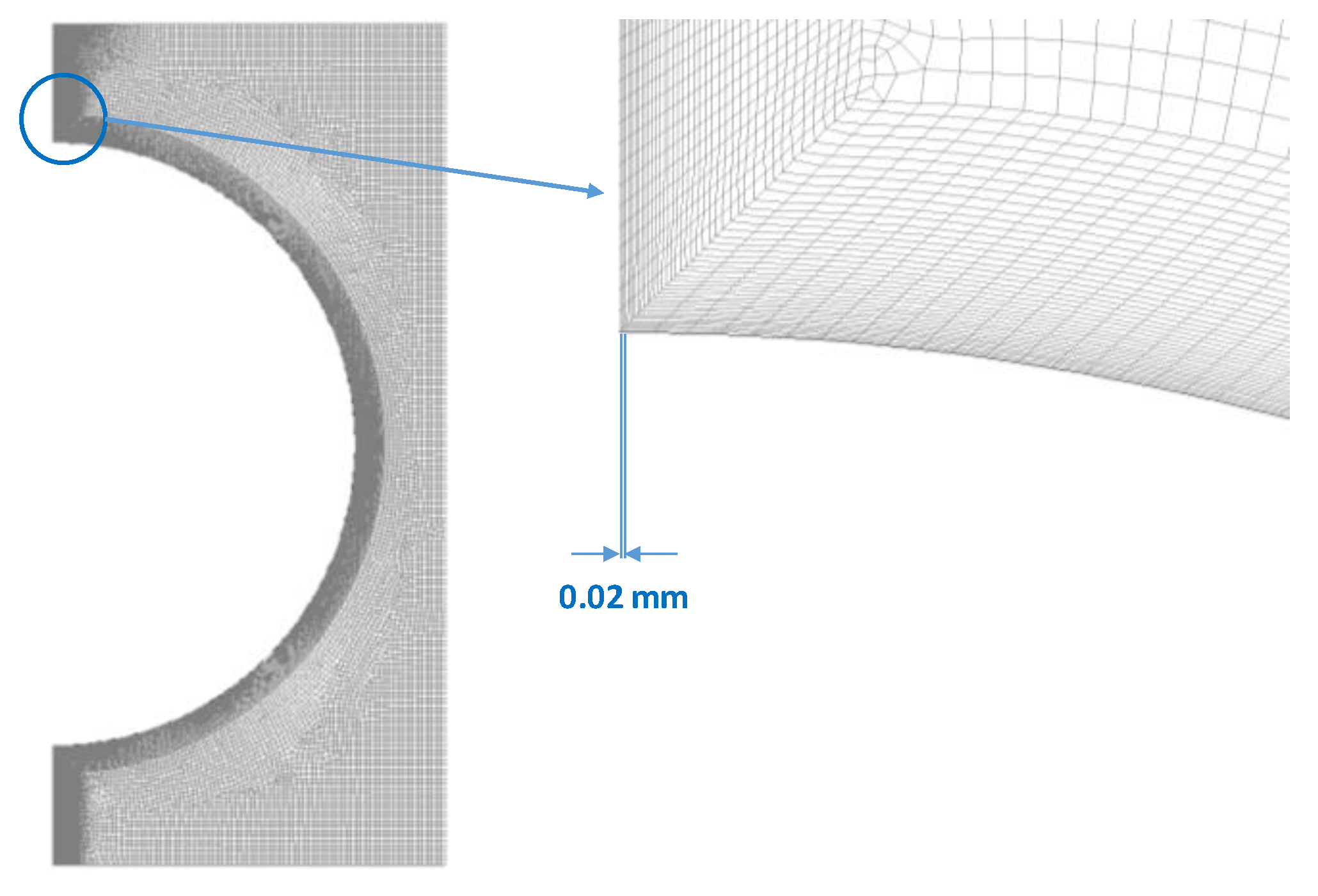
The domain is meshed quadrilateral dominant elements, and fine boundary layers are provided along the y-axis and tube wall in order to accurately capture the film distribution, as shown in Figure 2. The minimum thickness of the boundary layer is 0.02 mm adjacent to the wall. The conservation of mass and momentum are discretized across each cell in a commercial CFD code, i.e., Ansys Fluent v18.0 (Ansys Inc., Canonsburg, [Pa], United States). A second-order upwind scheme is used for Equation (9), semi-implicit method for pressure linked equations (SIMPLE) algorithm is applied for pressure-velocity coupling and pressure staggering option (PRESTO) is employed for pressure approximation. For void fraction gradient, a piecewise linear interpolation method known as geo-reconstruct scheme is implemented. The gradients are evaluated at the center of cell using a Green‒Gauss cell-based approach. The deduced equations are solved for each cell in a first-order implicit routine for an unsteady solution.

3.6. Mesh Dependency Test

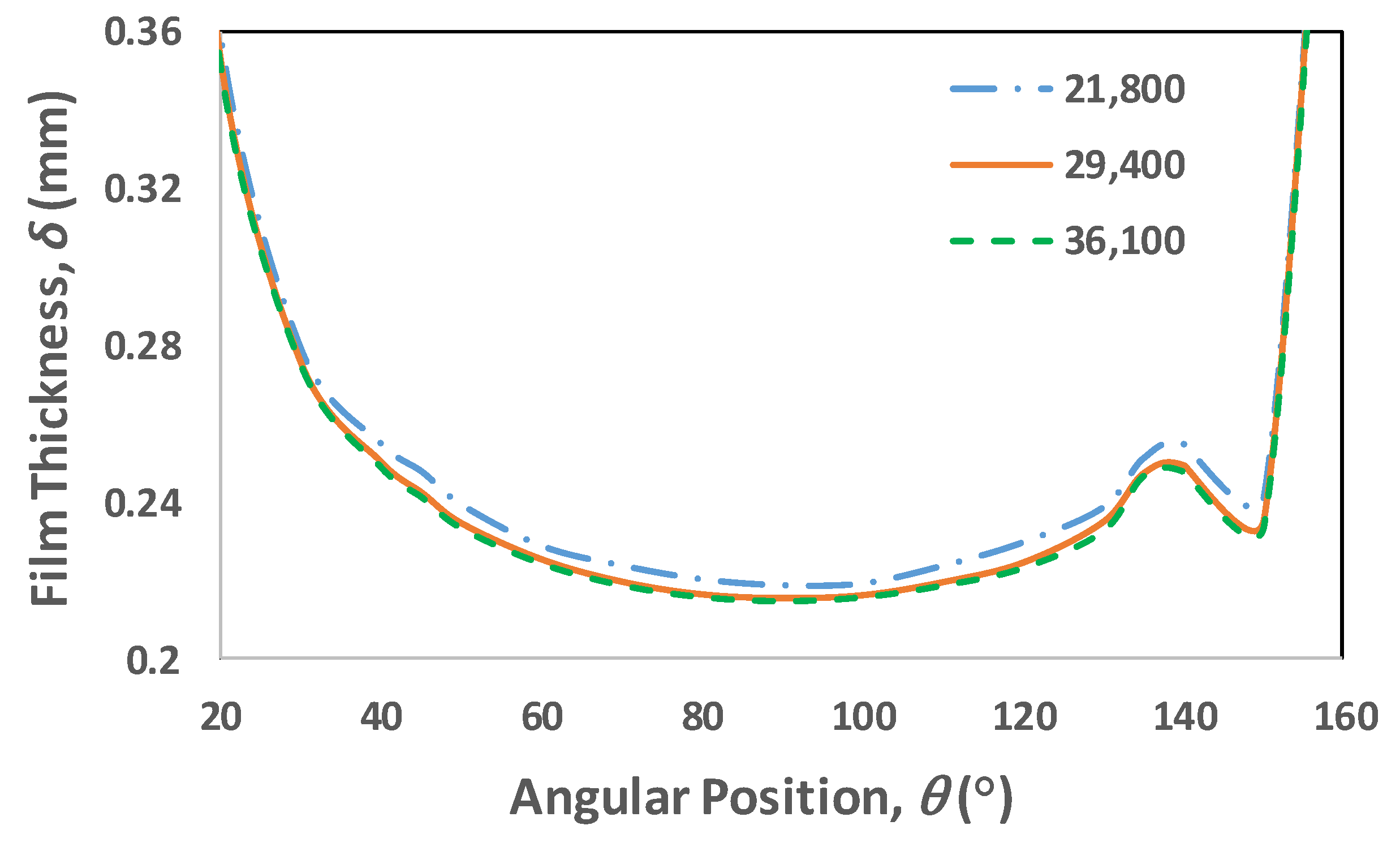
To obtain better results with the least computational effort, a mesh dependency test was performed. Three different meshes with 21,800, 29,400, and 36,100 elements were chosen and solved for Γ1/2 = 0.01 kg/(m·s) and C = 0.65. Figure 3 shows the film thickness distribution when the film completely covers the tube surface, i.e., t = 2.79 s. As is evident from the film distribution, when the mesh size increased from 21,800 to 29,400 elements, the distribution changed. However, a further increase in the mesh size led to minimal deviation. Hence, to save computational time, a mesh with 29,400 elements was selected for the numerical calculations. In addition, a time step of 10 μs was selected after the time dependency test.

3.7. Validation

The CFD model was compared with the experimental data by Hou et al. [24] for a 25.4-mm tube with 10 mm intertube spacing under Ref = 574, as shown in Figure 4a. The CFD model predicts well the film thickness distribution, with a maximum error of 16.9% in the range of θ = 30°–160° and 25.6% for θ = 20° near the impingement. In Figure 4b, the time-averaged film thickness for Γ1/2 = 0.01 kg/(m·s) and C = 0.65 is equated with the Nusselt film thickness and found to be in good agreement, with a maximum error of 13.3% at θ = 20°.

4. Results and Discussion

4.1. Transient Analysis

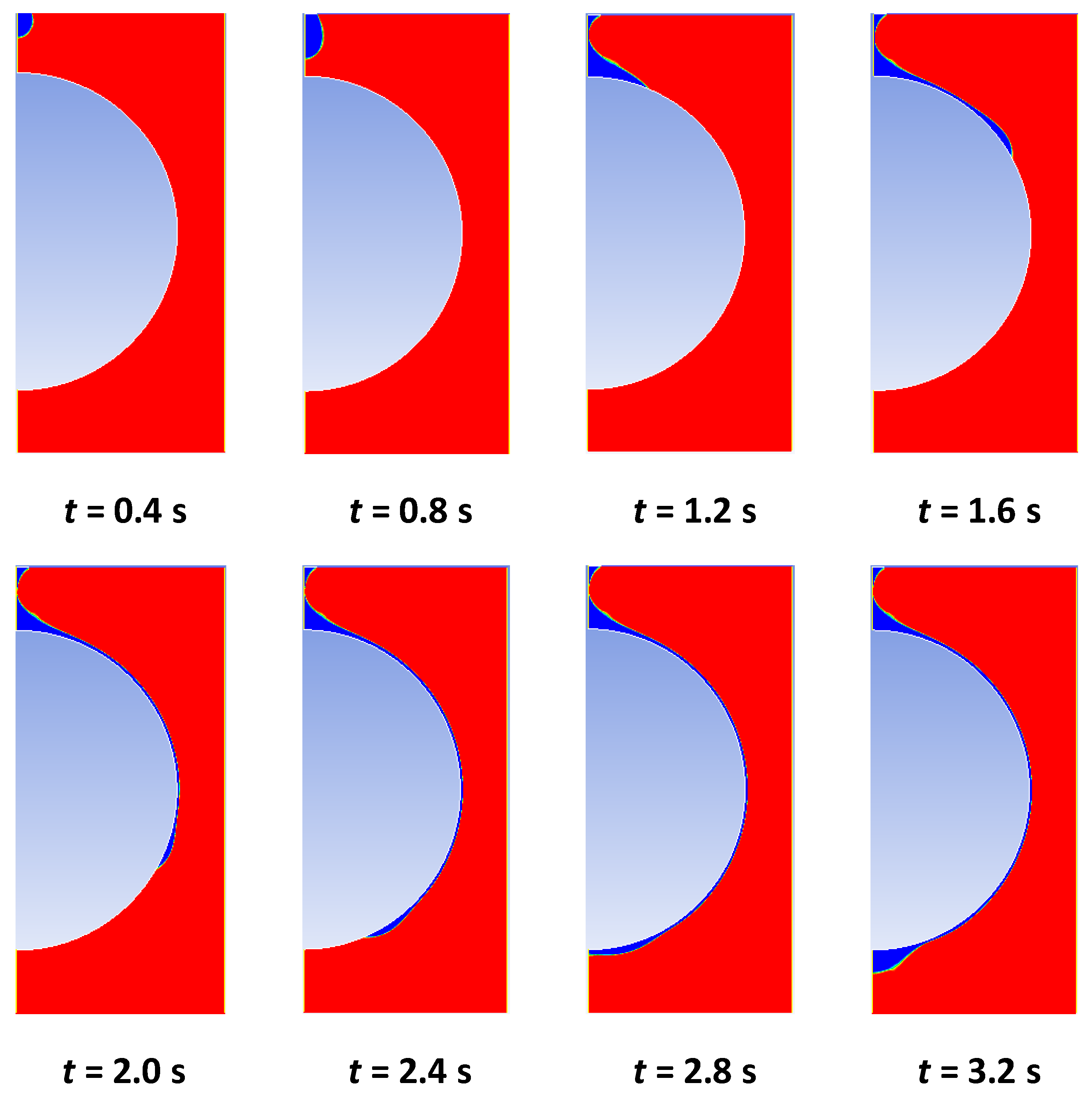
Figure 5 shows the volume fraction contours of the LiBr solution (blue region) with a liquid load of Γ1/2 = 0.01 kg/(m·s) and concentration of C = 0.65. At t = 0.4 s, the liquid falls freely with gravity as the driving force and is opposed by the surface tension, which attempts to form a droplet shape, as shown at t = 0.8 s. At t = 1.2 s, the liquid hits the top of the tube and starts spreading around the tube wall. The impact region is known as the stagnation point; as the liquid spreads it enters stagnation and then the developing region. At t = 1.6 s, the liquid continues to spread, forming a thin layer of LiBr solution. At this stage, the liquid film is in the developing region, as the velocity profiles within the film are not fully developed. From t = 2 s to 2.4 s, the tube surface is mostly covered by liquid film and the flow is fully developed. At t = 2.8 s, the tube is entirely covered with a thin layer of LiBr solution and the liquid starts gathering underneath the tube. The adhesion and surface tension forces hold the liquid at the bottom and prevent it from falling. The liquid keeps on gathering until the inertial force dominates and the liquid separates from the tube surface and falls freely.
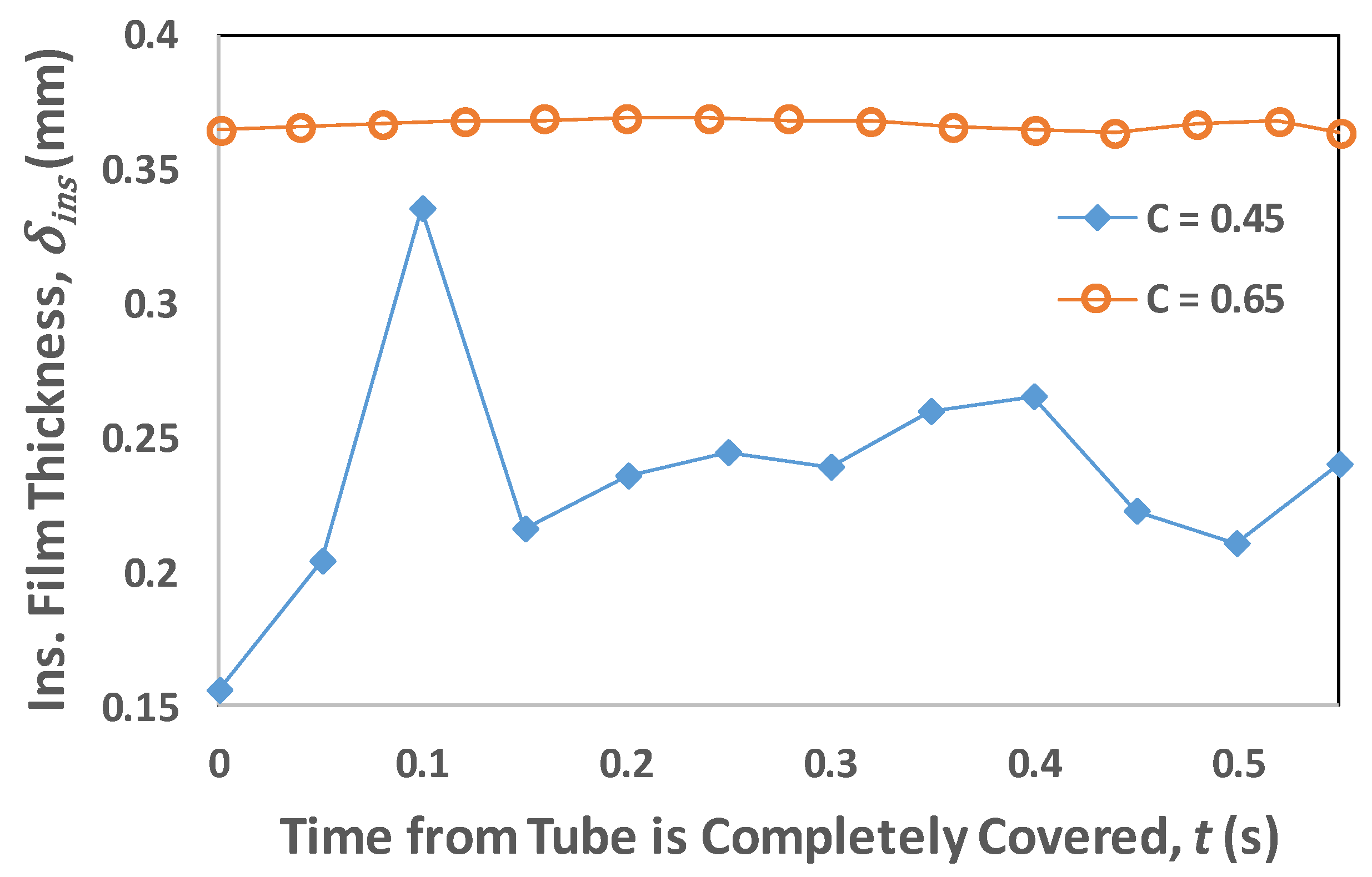
Figure 6a,b shows the film thicknesses δins at an angular position ranging from 5° to 175° for different time instants under the operating conditions of Γ1/2 = 0.01 kg/(m·s) and C = 0.45/0.65. It is clear that the film thickness pattern is not fixed, but changes with respect to time. Therefore, for comparison and analysis, the time-averaged film thickness δ is considered in this work. The time-averaged film thickness profile is represented by the solid line in Figure 6a,b. The jet mode is usually considered steady with weak perturbations. Figure 7 displays the transient behavior of film thickness at θ = 90° for a liquid load corresponding to the jet mode with C = 0.45 and 0.65. For C = 0.45, the instantaneous film thickness varies over time after the tube is completely wet and becomes stable with an average thickness of 0.245 mm. However, there remain some fluctuations, with a maximum deviation of 14.1%. At C = 0.65, the density and viscosity are 24.8% and 384% higher than at C = 0.45. The dense, viscous fluid rapidly becomes stable, with very low fluctuations of +0.5%. The perturbations positively affect the heat and mass transfer, and are present for a low-density and viscous fluid such as C = 0.45.

4.2. Film Thickness and Residence Time

The effect of liquid load on film thickness distribution is shown in Figure 8a,b. The film thickness decreases as the fluid moves from top to bottom, until it reaches to a minimum value, which is around θ = 90°. After that, the film thickness again begins to rise, sharply near the bottom of the tube, which is after θ = 150° due to the accumulation of liquid. As the liquid load is increased from 0.01 kg/(m·s) to 0.03 kg/(m·s), the film distribution shifts upwards for both C = 0.45 and C = 0.65. However, when the liquid load is raised from 0.03 kg/(m·s) to 0.05 kg/(m·s), the growth in film thickness is smaller than that of 0.01 kg/(m·s) to 0.03 kg/(m·s). This is because it follows the same trend as in Equation (7), which implies that the film thickness is directly proportional to the cubic root of liquid load, keeping the other parameters constant:
δ   α   Γ 1 / 2 3 .
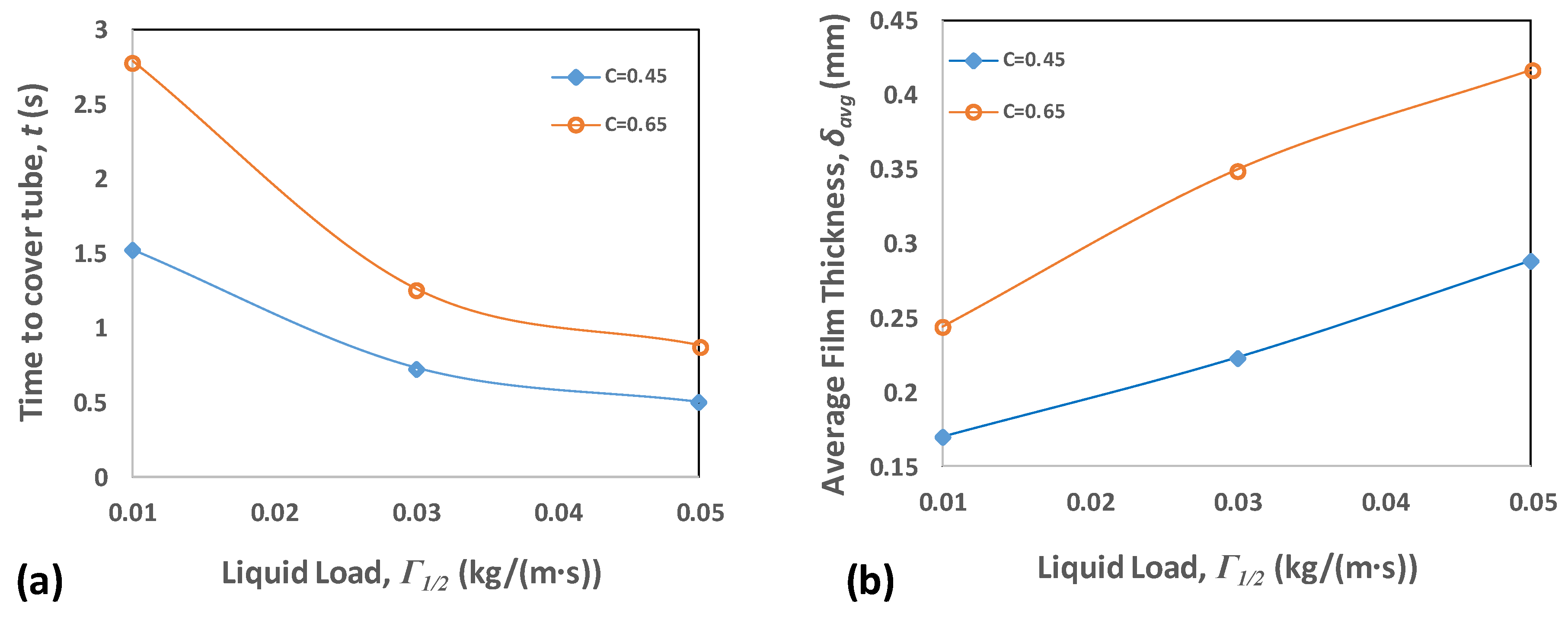
With the same liquid load value, the film thickness of C = 0.65 is higher than that of C = 0.45 because the density and viscosity vary with concentration. Figure 9a represents the time required for the tube surface to be completely covered by the liquid film. The higher film thickness for C = 0.65 with the same mass flux indicates a smaller fluid velocity field, which means a dense, viscous fluid needs more time for tube surface coverage. This indicates that the residence time for a higher concentration is more than that for a lower concentration, which means that more heat transfer is possible due to the higher residence time. On the other hand, the higher thickness results in increased thermal resistance, which is undesirable for heat transfer. At Γ1/2 = 0.01 kg/(m·s), the time needed for C = 0.65 and C = 0.45 is 2.79 s and 1.52 s, respectively. With the increase in liquid load, the fluid moves faster with a higher velocity field. Thus, the coverage time decreases to 0.88 s and 0.5 s for C = 0.65 and C = 0.45, respectively. The film thickness in the impingement and detachment zones, as shown in Figure 6a, is much greater than the in-between zone, i.e., θ = 20°–160°. Therefore, the average film thickness δavg is evaluated for θ = 20–160° and is presented in Figure 9b, with liquid load and concentration variation. The average thickness for C = 0.65 is 43.3% at 0.01 kg/(m·s) and 44% at 0.05 kg/(m·s), higher than that for C = 0.45. The higher average film thickness is due to a change in thermophysical properties with concentration.

4.3. Velocity Distribution

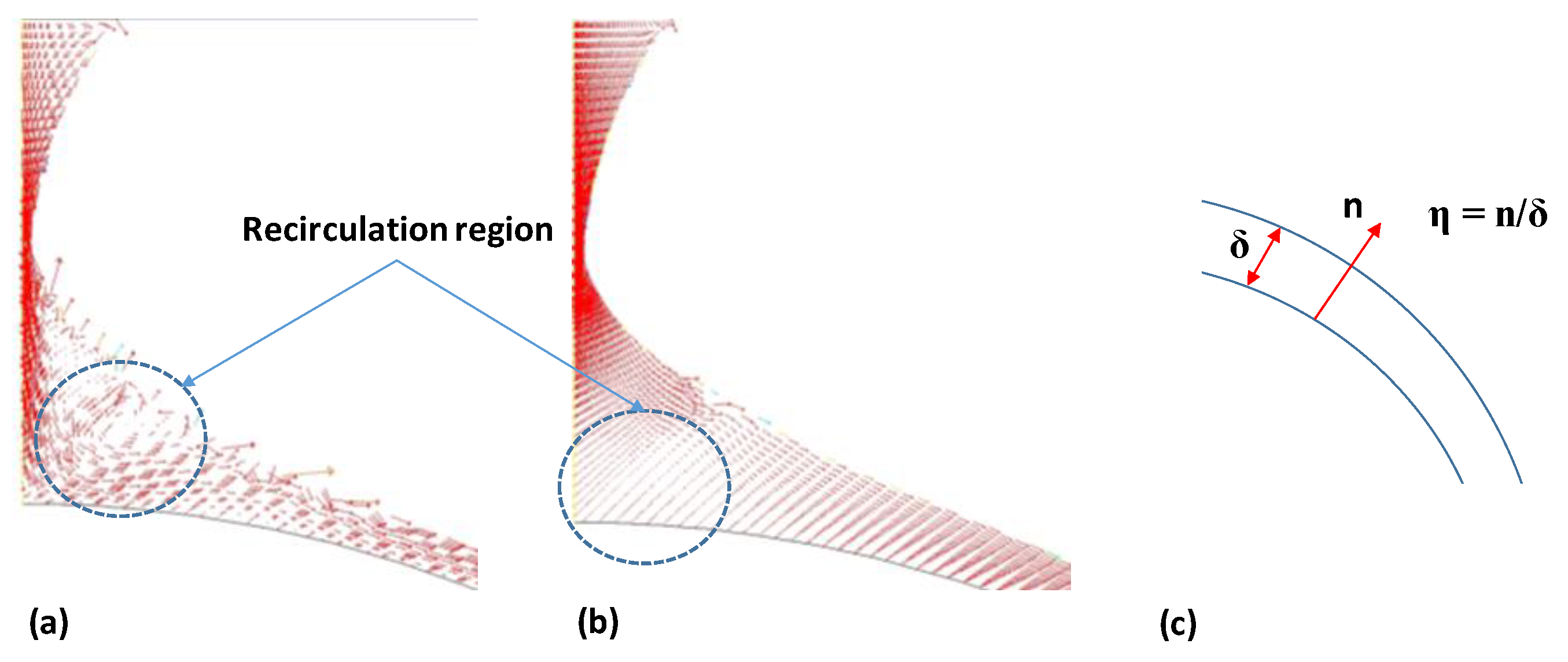
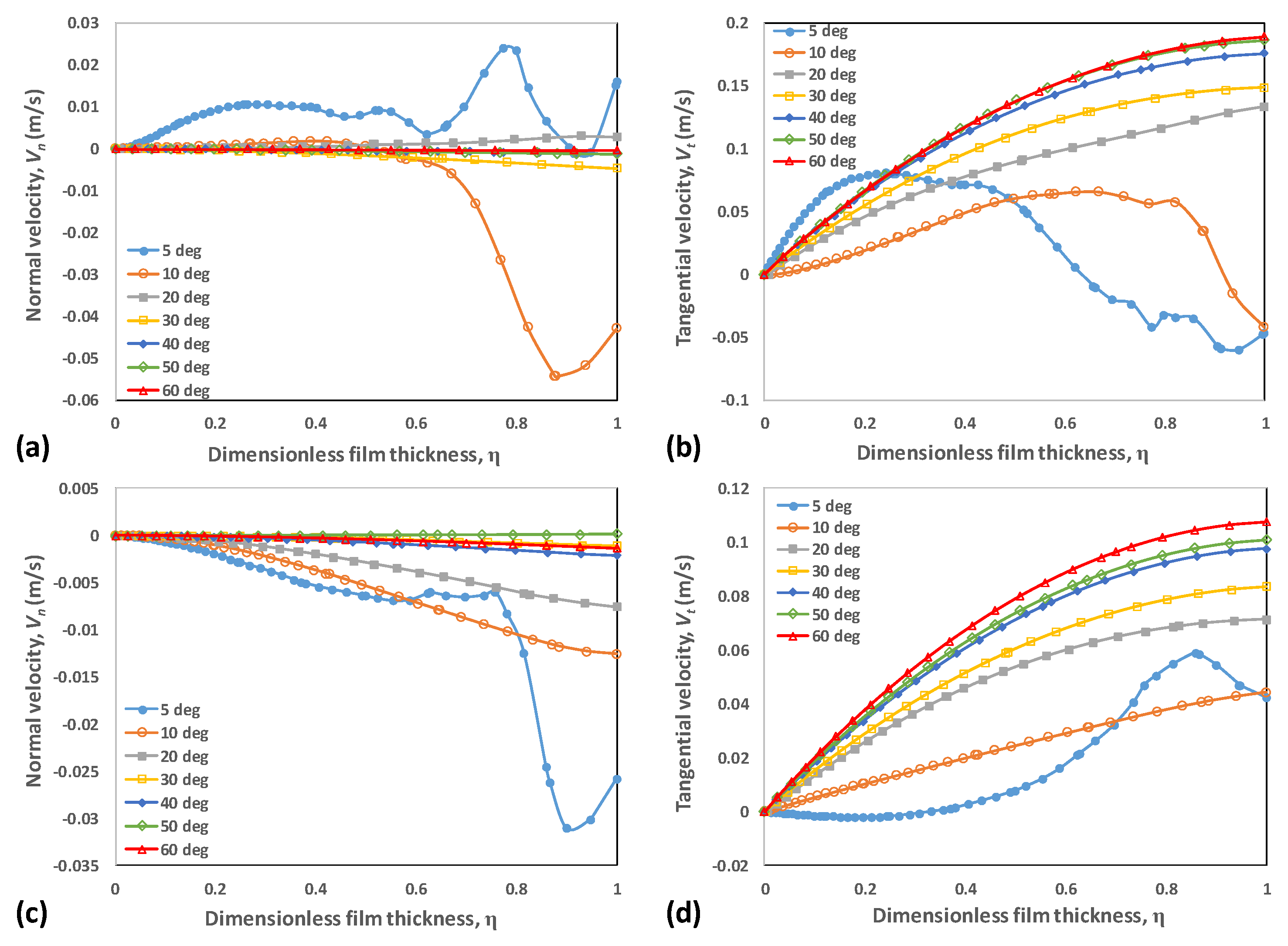
Figure 10a,b show velocity vectors at 0.05 kg/(m·s) for low and high concentrations. As the fluid falls and hits the tube, recirculation within the film begins. These recirculation formations enhance the fluid mixing and convection effects in the impingement and developing zones. Higher recirculation results in improved thermal performance [42]. The velocity vectors for C = 0.45 exhibit stronger recirculation than is seen for C = 0.65. The higher density and viscosity result in higher inertial force, which opposes recirculation. The film thickness has been normalized to dimensionless film thickness, as shown in Figure 10c, for comparison purposes. Figure 11a,b shows the normal Vn and tangential velocity Vt components for C = 0.45 and angular position ranging from 5° to 60°. The normal velocity profile at 5° displays fluid flow in the positive, normal direction. Moreover, it is clear from the tangential velocity profile that the fluid near the wall is moving downward, while some part is flowing in the opposite direction. This behavior shows recirculation phenomena in the film. The maximum normal and tangential velocity opposite to the mainstream flow at 5° were found to be 0.024 m/s and 0.06 m/s, respectively. The recirculation can be seen up to 10°, which is evident in the normal and tangential velocity components. From 20°, the flow in the film starts developing, the tangential component keeps rising because of the gravitational and inertial force, and the tangential component profile gets fully developed from 40°. The maximum tangential velocity at 60° is found to be 0.189 m/s. The normal velocity magnitude decreases as the flow develops, which is apparent from the normal velocity profiles for 20–60°. Figure 11c,d shows the normal and tangential velocity components for C = 0.65. In this case, the velocity profiles reflect the weak recirculation. The maximum tangential velocity opposite to the flow is 0.0021 m/s, which is 96.5% lower than for C = 0.45. Here, the flow enters the developing region from 10° and the tangential velocity component increases. The flow is developed at 40°, with tangential velocity increasing 30° onwards. The maximum tangential velocity at 60° is 0.108 m/s, which is 42.8% less than for C = 0.45. Hence, the less dense and viscous flow (C = 0.45) possesses strong recirculation and higher velocity, which may enhance the heat and mass transfer process when matched with a fluid of high density and viscosity (C = 0.65).

4.4. Thermal Resistance

The thermal performance of falling film evaporators depends on the overall heat transfer coefficient or total thermal resistance, which is the reciprocal of the first. The total thermal resistance Rtot is the sum of all thermal resistances in the falling film network, which can be mathematically described as:
R t o t = R i n t + R w + R c o n d + R e v a p ,
where Rint is the thermal resistance of internal flow, Rw is the tube wall thermal resistance, Rcond is the conduction thermal resistance of liquid film, and Revap is the thermal resistance by evaporation. From a hydrodynamics study, Rcond can be computed by the following equation:
R c o n d =   δ k .
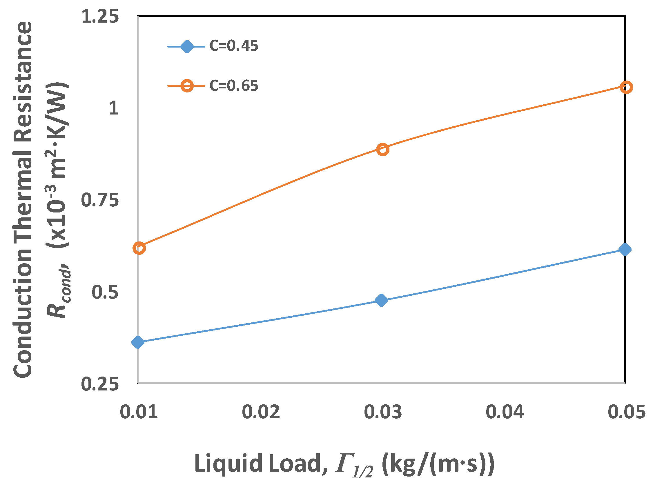
Figure 12 shows the average conduction thermal resistance variation with liquid load and concentration for θ = 20°–160°. The average thermal resistance at 0.01 kg/(m·s) and C = 0.45 is 0.361 × 10⁻³ m2·K/W, whereas the thermal resistance is 0.621 × 10⁻³ m2·K/W for C = 0.65, which is 72% higher. Furthermore, the thermal resistance increases with the liquid load for both concentrations. The main factors are the film thickness, which is higher for C = 0.65, and the thermal conductivity, which decreases with an increasing LiBr concentration. At 0.05 kg/(m·s), the thermal resistance for C = 0.65 is 72.9% higher than that of C = 0.45. It can be deduced that, with increasing liquid load and concentration, the heat transfer rate may decrease because of the higher thermal resistance.

5. Conclusions

The CFD model of an aqueous LiBr solution falling over a horizontal tube was developed in this work. The effects of LiBr concentration and liquid load on falling film distribution were analyzed. It was found that jet mode, corresponding to 0.05 kg/(m·s), was more stable at a higher concentration, i.e., C = 0.65, with small fluctuations of +0.5%. In contrast, low concentration (C = 0.45) flow with 0.05 kg/(m·s) had maximum fluctuations of 14.1%. The film thickness increased with concentration and liquid load, and the residence time increased with higher concentration and lower liquid loads. The average film thickness and residence time at 0.05 kg/(m·s) and C = 0.65 were found to be 44% and 76% higher than for C = 0.45, respectively. Weak recirculation was observed for higher concentration; the recirculation exists until 5° for C = 0.65 and 10° for C = 0.45. In addition, the maximum tangential velocity when the flow was developed was 0.108 m/s for C = 0.65, vs. 0.189 m/s for C = 0.45. The flow was fully developed at θ = 40° for both concentrations. The thermal resistance analysis demonstrated that the thermal resistance rises with the concentration and liquid load. For Γ1/2 = 0.05 kg/(m·s), the thermal resistance for C = 0.65 was 72.9% higher than that of C = 0.45. It may be deduced from this hydrodynamics study that the heat transfer performance is expected to be better at lower concentrations because of the lower film thickness, more recirculation, higher velocity, and lower thermal resistance. In practical applications, such as refrigeration and desalination, this implies that regions in falling film evaporators with low concentration would have better thermal performance as compared to high concentration regions.

Author Contributions

Conceptualization, A.M. and M.K.; methodology, F.T.; software, F.T.; validation, F.T.; formal analysis, M.K.; investigation, F.T. and A.M.; resources, A.M. and M.K.; data curation, A.M.; writing—original draft preparation, F.T.; writing—review and editing, A.M. and M.K.; visualization, F.T.; supervision, A.M. and M.K.; project administration, A.M. and M.K.; funding acquisition, F.T. All authors have read and agreed to the published version of the manuscript.

Funding

The publication of this article was funded by the Qatar National Library (QNL).

Acknowledgments

The authors would like to acknowledge the resources and support provided by the College of Science and Engineering (CSE) and the Qatar Environment and Energy Research Institute (QEERI) of Hamad Bin Khalifa University (HBKU). The publication of this article was funded by the Qatar National Library.

Conflicts of Interest

The authors declare no conflict of interest.

Nomenclature

CLiBr mass concentration (%)
CFDcomputational fluid dynamics
CSFcontinuum surface force
Dtube diameter (m)
Fforce (N)
gacceleration due to gravity (m/s2)
Gamodified Galileo number
hiimpingement height (m)
kthermal conductivity (W·m/K)
Kcurvature
LiBrlithium bromide
PRESTOpressure staggering option
Rthermal resistance (m2·K/W)
Reffilm Reynolds number
sintertube spacing (m)
SIMPLEsemi-implicit method for pressure linked equations
ttime (s)
Vvelocity (m/s)
VOFvolume of fluid
Greek letters
αvoid fraction
σsurface tension (N/m)
μviscosity (Pa·s)
Γ1/2liquid load, on one side of tube (kg/(m·s))
ρdensity (kg/m3)
δfilm thickness (m)
θangular position (°)
θwwall adhesion contact angle (°)
ηdimensionless film thickness
Subscripts
avgtime averaged from θ = 20–160°
condconduction
evapevaporation
ggaseous phase
intinternal
insinstantaneous
lliquid phase
nnormal
ttangential
tottotal
wwall
volvolumetric

References

  1. Danilova, G.N.; Burkin, V.G.; Dyundin, V.A. Heat transfer in spray-type refrigerator evaporators. Heat Transf. Res. 1976, 8, 105–113. [Google Scholar]
  2. Lorenz, J.J.; Yung, D. Film Breakdown and Bundle-Depth Effects in Horizontal-Tube, Falling-Film Evaporators. J. Heat Transf. 1982, 104, 569–571. [Google Scholar] [CrossRef]
  3. Gonzalez, G.J.M.; Jabardo, J.M.S.; Stoecker, W.F. Falling Film Ammonia Evaporators; University of Illinois: Champaign, IL, USA, 1992. [Google Scholar]
  4. Zeng, X.; Chyu, M.-C.; Ayub, D.Z.H. Evaporation heat transfer performance of nozzle-sprayed ammonia on a horizontal tube. ASHRAE Trans. 1995, 101, 136–149. [Google Scholar]
  5. Hoffmann, L.; Greiter, I.; Wagner, A.; Weiss, V.; Alefeld, G. Experimental investigation of heat transfer in a horizontal tube falling film absorber with aqueous solutions of LiBr with and without surfactants. Int. J. Refrig. 1996, 19, 331–341. [Google Scholar] [CrossRef]
  6. Kwon, K.; Jeong, S. Effect of vapor flow on the falling-film heat and mass transfer of the ammonia/water absorber. Int. J. Refrig. 2004, 27, 955–964. [Google Scholar] [CrossRef]
  7. Ribatski, G.; Jacobi, A.M. Falling-film evaporation on horizontal tubes—A critical review. Int. J. Refrig. 2005, 28, 635–653. [Google Scholar] [CrossRef]
  8. Fernández-Seara, J.; Pardiñas, Á.Á. Refrigerant falling film evaporation review: Description, fluid dynamics and heat transfer. Appl. Therm. Eng. 2014, 64, 155–171. [Google Scholar] [CrossRef]
  9. Tahir, F.; Mabrouk, A.; Koc, M. Review on CFD analysis of horizontal falling film evaporators in multi effect desalination plants. Desalin. Water Treat. 2019, 166, 296–320. [Google Scholar] [CrossRef]
  10. Tahir, F.; Mabrouk, A.; Koc, M. CFD Analysis of Falling Film Wettability in MED Desalination plants. In Proceedings of the Qatar Foundation Annual Research Conference Proceedings, Ar-Rayyan, Qatar, 19–20 March 2018; Volume 2018, p. EEPD650. [Google Scholar]
  11. Tahir, F.; Mabrouk, A.A.; Koc, M. CFD analysis of spray nozzle arrangements for multi effect desalination evaporator. In Proceedings of the 3rd Thermal Fluids Engineering Conference, Ft. Lauderdale, FL, USA, 4–7 March 2018; pp. 935–941. [Google Scholar]
  12. Mabrouk, A.A.; Bourouni, K.; Abdulrahim, H.K.; Darwish, M.; Sharif, A.O. Impacts of tube bundle arrangement and feed flow pattern on the scale formation in large capacity MED desalination plants. Desalination 2015, 357, 275–285. [Google Scholar] [CrossRef]
  13. Mitrovic, J. Flow structures of a liquid film falling on horizontal tubes. Chem. Eng. Technol. 2005, 28, 684–694. [Google Scholar] [CrossRef]
  14. Hu, X.; Jacobi, A.M. The Intertube Falling Film: Part 1—Flow Characteristics, Mode Transitions, and Hysteresis. J. Heat Transf. 1996, 118, 616–625. [Google Scholar] [CrossRef]
  15. Hu, X.; Jacobi, A.M. Flow characteristics of liquid droplets and jets falling between horizontal circular tubes. In Experimental Heat Transfer, FLuid Mechanics and Thermodynamics; PISA, Edizioni ETS: Paris, France, 1997; pp. 1295–1302. [Google Scholar]
  16. Roques, J.F.; Dupont, V.; Thome, J.R. Falling Film Transitions on Plain and Enhanced Tubes. J. Heat Transf. 2002, 124, 491–499. [Google Scholar] [CrossRef]
  17. Roques, J.-F.; Thome, J.R. Falling Film Transitions Between Droplet, Column, and Sheet Flow Modes on a Vertical Array of Horizontal 19 FPI and 40 FPI Low-Finned Tubes. Heat Transf. Eng. 2003, 24, 40–45. [Google Scholar] [CrossRef]
  18. Nusselt, W. Die oberflachenkondensation des wasserdamphes. VDI-Zs 1916, 60, 541–546. [Google Scholar]
  19. Ji, G.; Wu, J.; Chen, Y.; Ji, G. Asymmetric distribution of falling film solution flowing on hydrophilic horizontal round tube. Int. J. Refrig. 2017, 78, 83–92. [Google Scholar] [CrossRef]
  20. Hosseinnia, S.M.; Naghashzadegan, M.; Kouhikamali, R. CFD simulation of water vapor absorption in laminar falling film solution of water-LiBr—Drop and jet modes. Appl. Therm. Eng. 2017, 115, 860–873. [Google Scholar] [CrossRef]
  21. Ding, H.; Xie, P.; Ingham, D.; Ma, L.; Pourkashanian, M. Flow behaviour of drop and jet modes of a laminar falling film on horizontal tubes. Int. J. Heat Mass Transf. 2018, 124, 929–942. [Google Scholar] [CrossRef]
  22. Rogers, J.T.; Goindi, S.S. Experimental laminar falling film heat transfer coefficients on a large diameter horizontal tube. Can. J. Chem. Eng. 1989, 67, 560–568. [Google Scholar] [CrossRef]
  23. Gstoehl, D.; Roques, J.F.; Crisnel, P.; Thome, J.R. Measurement of Falling Film Thickness Around a Horizontal Tube Using a Laser Measurement Technique. Heat Transf. Eng. 2004, 25, 28–34. [Google Scholar] [CrossRef]
  24. Hou, H.; Bi, Q.; Ma, H.; Wu, G. Distribution characteristics of falling film thickness around a horizontal tube. Desalination 2012, 285, 393–398. [Google Scholar] [CrossRef]
  25. Chen, X.; Shen, S.; Wang, Y.; Chen, J.; Zhang, J. Measurement on falling film thickness distribution around horizontal tube with laser-induced fluorescence technology. Int. J. Heat Mass Transf. 2015, 89, 707–713. [Google Scholar] [CrossRef]
  26. Lin, S.; Liu, X.; Li, X. The spatial distribution of liquid film thickness outside the horizontal falling film tube. Int. J. Heat Mass Transf. 2019, 143, 118577. [Google Scholar] [CrossRef]
  27. Wang, J.; Chen, X.; Lu, T.; Chen, X.; Shen, S.; Liu, B. Three-dimensional film thickness distribution of horizontal tube falling film with column flow. Appl. Therm. Eng. 2019, 154, 140–149. [Google Scholar] [CrossRef]
  28. Tahir, F.; Baloch, A.A.B.; Ali, H. Resilience of Desalination Plants for Sustainable Water Supply in Middle East. In Sustainability Perspectives: Science, Policy and Practice, Strategies for Sustainability; Khaiter, P.A., Erechtchoukova, M.G., Eds.; Springer Nature Switzerland AG: Basel, Switzerland, 2020; pp. 303–329. ISBN 978-3-030-19550-2. [Google Scholar]
  29. Tahir, F.; Mabrouk, A.; Koc, M. Energy and exergy analysis of thermal vapor compression (TVC) and absorption vapor compression (AVC) for multi effect desalination (MED) plants. In Proceedings of the 8th Global Conference on Global Warming (GCGW), Doha, Qatar, 22–25 April 2019; p. 25. [Google Scholar]
  30. Mabrouk, A.; Abotaleb, A.; Abdelrehim, H.; Tahir, F.; Koc, M.; Abdelrashid, A.; Nasralla, A. High Performance MED Desalination Plants, Part II: Novel Integration MED-Absorption Vapor Compression. In Proceedings of the IDA 2017 World Congress on Water Reuse and Desalination, Sao Paulo, Brazil, 15–20 October 2017. [Google Scholar]
  31. Narváez-Romo, B.; Chhay, M.; Zavaleta-Aguilar, E.W.; Simões-Moreira, J.R. A critical review of heat and mass transfer correlations for LiBr-H2O and NH3-H2O absorption refrigeration machines using falling liquid film technology. Appl. Therm. Eng. 2017, 123, 1079–1095. [Google Scholar] [CrossRef] [Green Version]
  32. Pátek, J.; Klomfar, J. A computationally effective formulation of the thermodynamic properties of LiBr–H2O solutions from 273 to 500K over full composition range. Int. J. Refrig. 2006, 29, 566–578. [Google Scholar]
  33. Kaushik, S.C.; Arora, A. Energy and exergy analysis of single effect and series flow double effect water–lithium bromide absorption refrigeration systems. Int. J. Refrig. 2009, 32, 1247–1258. [Google Scholar] [CrossRef]
  34. Khan, S.A.; Tahir, F.; Baloch, A.A.B.; Koc, M. Review of Micro–Nanoscale Surface Coatings Application for Sustaining Dropwise Condensation. Coatings 2019, 9, 117. [Google Scholar] [CrossRef] [Green Version]
  35. Hirt, C.; Nichols, B. Volume of fluid (VOF) method for the dynamics of free boundaries. J. Comput. Phys. 1981, 39, 201–225. [Google Scholar] [CrossRef]
  36. Baloch, A.; Ali, H.; Tahir, F. Transient Analysis of Air Bubble Rise in Stagnant Water Column Using CFD. In Proceedings of the ICTEA: International Conference on Thermal Engineering, Doha, Qatar, 25–28 February 2018; Volume 2018. [Google Scholar]
  37. Nigim, T.H.; Eaton, J.A. CFD prediction of the flashing processes in a MSF desalination chamber. Desalination 2017, 420, 258–272. [Google Scholar] [CrossRef]
  38. Ozmen-Cagatay, H.; Kocaman, S. Dam-Break Flow in the Presence of Obstacle: Experiment and CFD Simulation. Eng. Appl. Comput. Fluid Mech. 2011, 5, 541–552. [Google Scholar] [CrossRef] [Green Version]
  39. Lopes, R.J.G.; Quinta-Ferreira, R.M. Assessment of CFD−VOF Method for Trickle-Bed Reactor Modeling in the Catalytic Wet Oxidation of Phenolic Wastewaters. Ind. Eng. Chem. Res. 2010, 49, 2638–2648. [Google Scholar] [CrossRef]
  40. Gupta, R.; Fletcher, D.F.; Haynes, B.S. On the CFD modelling of Taylor flow in microchannels. Chem. Eng. Sci. 2009, 64, 2941–2950. [Google Scholar] [CrossRef]
  41. Brackbill, J.; Kothe, D.; Zemach, C. A continuum method for modeling surface tension. J. Comput. Phys. 1992, 100, 335–354. [Google Scholar] [CrossRef]
  42. Yang, L.; Liu, Y.; Yang, Y.; Shen, S. Microscopic mechanisms of heat transfer in horizontal-tube falling film evaporation. Desalination 2016, 394, 64–71. [Google Scholar] [CrossRef]
Figure 1. 2D geometry with boundary conditions.
Energies 13 00307 g001
Figure 2. Mesh with fine boundary layers for CFD analysis.
Energies 13 00307 g002
Figure 3. Film thickness distribution for Γ1/2 = 0.01 kg/(m·s) and C = 0.65 at t = 2.79 s.
Energies 13 00307 g003
Figure 4. CFD model comparison of (a) experimental data by Hou et al. [24] and (b) Nusselt solution as in Equation (7).
Energies 13 00307 g004
Figure 5. Volume fraction contours for Γ1/2 = 0.01 kg/(m·s) and C = 0.65 w.r.t. time.
Energies 13 00307 g005
Figure 6. Film thickness at different times after the tube is completely covered and time-averaged film thickness profiles for Γ1/2 = 0.01 kg/(m·s) and (a) C = 0.45, and (b) C = 0.65.
Energies 13 00307 g006
Figure 7. Instantaneous film thickness at θ = 90° for Γ1/2 = 0.05 kg/(m·s).
Energies 13 00307 g007
Figure 8. Film thickness distribution w.r.t. liquid load for (a) C = 0.45 and (b) C = 0.65.
Energies 13 00307 g008
Figure 9. (a) Time required for the complete wetting of tube and (b) average film thickness for different liquid loads and concentrations.
Energies 13 00307 g009
Figure 10. Velocity vector for Γ1/2 = 0.05 kg/(m·s) and (a) C = 0.45 (b) C = 0.65 and (c) dimensionless film thickness η schematic.
Energies 13 00307 g010
Figure 11. Velocity profile for Γ1/2 = 0.05 kg/(m·s) and C = 0.45 (a) normal component and (b) tangential component; and for Γ1/2 = 0.05 kg/(m·s) and C = 0.65 (c) normal component and (d) tangential component.
Energies 13 00307 g011
Figure 12. Average conduction thermal resistance variation w.r.t. liquid load.
Energies 13 00307 g012
Table 1. Thermophysical properties of LiBr solution and water vapors.
FluidDensity (kg/m3)Viscosity (Pa-s)Surface Tension (N/m)
LiBr solutionC = 0.4514530.0022740.08
C = 0.6518140.011020.085
Water Vapors0.03040.0000101
Table 2. Films Reynolds number Ref and flow modes for all cases.
CΓ1/2 (kg/(m·s))RefGaTransitional Ref [16]Mode
Droplet to Droplet-JetDroplet-Jet to Jet
0.450.0117.62.84 × 10952.373Droplet
0.0352.8Droplet-Jet
0.0587.9Jet
0.650.013.67.7 × 1067.511Droplet
0.0310.9Droplet-Jet
0.0518.2Jet