Abstract
Photoelectrochemical water splitting is a promising pathway for solar-driven hydrogen production with a low environmental footprint. The utilization of solar concentrators to supply such water splitting devices with concentrated solar irradiation offers great potential to enhance the economic viability of water splitting at “sunny” site locations. In this work, we defined a set of functional requirements for solar concentrators to assess their suitability to power such water splitting devices, taking into account concentrator optical performance, device coupling efficiency, perceived system complexity, as well as technological costs and risks. We identified, classified and compared a broad range of existing solar concentrator design concepts. Our geometrical analysis, performed on a yearly basis with a one-minute time step, shows that two-axis tracking concentrators with water splitting devices positioned parallel to the optical aperture plane exhibit the highest potential, given the initial conditions applied for the device tilt constraints. Demanding an angle of at least 20° between horizontal and the front side of the water splitting device, allows the device to be operational for 97% of the daylight time in Seville, Spain. The relative loss with respect to the available direct normal irradiance is estimated to 6%. Results moderately depend on the location of application, but generally confirm that the consideration of tilt angle constraints is essential for a comprehensive performance assessment of photoelectrochemical water splitting driven by concentrated sunlight.
1. Introduction
The depletion of fossil fuels, rising world population, and climate change require a revision of the current energy system including a shift towards broad utilization of renewable energies with low environmental impact. Economical, sustainable, and scalable hydrogen (H2) production—replacing current hydrogen production methods dominated by steam reforming of natural gas, which widely rely on fossil feedstocks—is expected to be a viable long-term solution for the storage of intermittent renewable energy resources and the supply of a versatile, clean energy vector. Hydrogen can be used to generate electricity (e.g., via fuel cells in stationary applications or in the transportation sector) and heat (e.g., via combustion or combined heat and power). Furthermore, it can serve as a chemical feedstock for industrial applications (e.g., ammonia synthesis) and—together with captured carbon dioxide—for the production of a great variety of “green” hydrocarbons. As solar energy has the highest potential among available renewable energy resources to cover the future world energy demand, there is a consistent interest for the research community to develop and optimize energy conversion systems harvesting solar power to produce clean hydrogen [1,2,3,4,5,6,7].
Photoelectrochemical (PEC) water splitting is considered as one relevant pathway for sustainable hydrogen production and various potential application scenarios, e.g., single home system, hydrogen refueling stations and industrial processes, have been analyzed [8,9,10,11,12,13,14,15]. In PEC water splitting devices, photons are captured by photoabsorber(s) to generate electron/electron-hole pairs which finally drive the water splitting reactions. Simultaneously, hydrogen is formed at the cathode through a reduction reaction and oxygen (O2) is formed at the anode through an oxidation reaction. The photoabsorber(s) could either be in direct contact with the electrolyte (i.e., photoelectrode) or separated from it in various degrees of vicinity. Diverse configurations of PEC water splitting devices—amongst them PEC-PV (photoelectrochemical–photovoltaic) tandem devices, in which a PV cell is electrically connected in series to a photoelectrode and uses light not absorbed by the photoelectrode to provide additional voltage—have been introduced and investigated [16,17,18,19,20,21,22,23,24,25,26,27]. PEC(-PV) devices can be operated under non-concentrated (1 sun) or concentrated sunlight. Concentrated solar irradiation provided by non-imaging optical solar concentrators, which bundle Direct Normal Irradiance (DNI) with a concentration factor C depending on their geometrical configuration, offers increased current densities on active surfaces and significant potential to reduce system or rather hydrogen production costs as well as associated greenhouse gas emissions [8,16,28,29,30,31,32,33]. Such solar concentrators can be typically classified into point focusing (e.g., solar tower) and line focusing (e.g., parabolic trough) systems. The concentration of solar radiation can be achieved with canted reflector or lens facets. A concentration factor C of 100 was proposed as an upper limit for PEC(-PV) devices, due to cooling restrictions and high electrolysis currents [34], though the operation of an integrated PEC device at concentration factors up to 474 and an irradiation inhomogeneity—defined as (Cmax − Cmin)/Cmean—of about 20% has been demonstrated successfully [35].
Solar concentrators are mostly relevant for sunny regions (latitude within ±40° of equator) with minimal cloud cover and atmospheric extinction, where a DNI higher than 2000 kWh/m2/year is available. Previous studies focusing on system design guidelines for PEC(-PV) water splitting devices have emphasized their analysis on system performance, cost, and sustainability (in particular manufacture/operation energy demand and greenhouse gas emissions) for various system configurations, including different material choices for photoelectrodes and catalysts, combined with multi-junction or silicon-based PV cells [16], considering a few concentrator designs, i.e., two-axis tracking parabolic trough collectors, solar towers or point focusing Fresnel Lens arrays [28].
This study aims at reviewing and comparing the respective merits of a broader range of relevant concentrator design concepts, based on their optical performance and coupling constraints with PEC(-PV) water splitting devices, while taking into account secondary aspects such as perceived system complexity as well as perceived system costs and technological risks, in order to suggest variants and trade-offs for most relevant concentrator design concepts, compatible with PEC(-PV) devices.
2. Materials and Methods
2.1. Reference PEC(-PV) Device, Location and Conditions
For this study—without corrupting wide applicability, since the exact configuration and design of the PEC(-PV) device are not relevant here—we chose the CoolPEC cell developed by Vilanova et al. [17] with an irradiated active area of 50 cm2, to date, the largest water splitting PEC device demonstrated under concentrated sunlight, as a reference for a planar PEC(-PV) device. As illustrated in Figure 1a, counter-electrodes are placed at both sides of a central, oblong metal oxide photoanode, which absorbs incoming ultraviolet (UV) and part of the visible (Vis) light from the solar concentrator. The remaining fraction of Vis light as well as near-infrared (NIR) light penetrates the working electrode and finally encounters a PV cell at the back of the CoolPEC cell [17]. A CoolPEC module containing four identical PEC devices based on the CoolPEC design had been operated successfully on DLR’s test facility SoCRatus (see Figure 1b), which provides concentrated natural sunlight with a geometric concentration ratio of 20.2 [36,37]. Details of the CoolPEC geometry were omitted since this study is focused on general implications of the operation of PEC(-PV) devices with a solar concentrator. In addition to the reference PEC(-PV) device, which features an oblong shape, we also considered a square shaped device with an active area of 50 cm2.
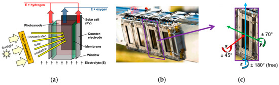
Figure 1.
(a) Illustration of the main parts of the CoolPEC cell (without body), in particular oblong photoanode and solar cell provided with concentrated irradiation from a solar concentrator, (b) CoolPEC module in the focal plane of the SoCRatus and (c) one of the incorporated photoelectrochemical (PEC) units with a 50-cm2 active cell area along with the reference Cartesian coordinate system and tilt constraints with respect to rotational axes.
Important system geometrical specifications for a coupling of such PEC(-PV) devices with solar concentrators are the cell orientation with respect to the concentrator optical aperture plane and corresponding tilt angle constraints. The tilt angle constraints reflect requirements of a PEC(-PV) device predominantly regarding efficient product gas separation and removal. Figure 1c shows one of the PEC units incorporated in the CoolPEC module along with estimated tilt angle constraints applied for the following analyses. The critical degree of freedom for an optimal coupling with a concentrator is in this case the rotation about the y-axis.
The reference location for the comparison of solar concentrator systems is Seville, Spain, which offers good weather conditions, in particular, a high level of Global Horizontal Irradiation (GHI) above 1900 kWh/m2/year [38] essential for successful application of Concentrating Solar Power (CSP) technologies. Moreover, the region features a good infrastructure, significant chemical industry activity, and great potential for the utilization of hydrogen [39].
For this study we set the maximum deviation of the local concentration ratio on the active area (here for the sake of convenience treated as equivalent to front window) of the PEC(-PV) device to ±20% related to the mean concentration ratio to ensure effective contribution of the complete active surface. Furthermore, we here consider a concentration ratio range between 20 and 100 to significantly increase the photon flux compared to operation under 1 sun on the one hand, but on the other hand to avoid an enormous cooling demand associated with higher concentration ratios.
2.2. System Requirements
Design criteria for a system coupling a solar concentrator with one of the PEC(-PV) devices introduced above are structured into four main functional requirements, i.e., (a) solar concentrator optical performance, (b) PEC(-PV) device efficiency, (c) perceived system complexity and (d) perceived technological costs and risks. These functional requirements and corresponding design criteria are guiding the inter-comparison of solar concentrators and the selection of the most suitable design concepts.
2.2.1. Solar Concentrator Optical Performance
The solar concentrator must focus DNI as efficiently as possible on the PEC(-PV) active area. A set of 10 design criteria was derived for this first functional requirement (F1).
(Crit01) Concentrated DNI flux has to be spatially uniform across the active area [29,40], allowing here a maximum deviation of 20% with respect to the mean irradiance level on the active surface. (Crit02) The global concentration ratio C has to be compatible and it should be adjustable within the expected optimal range (20–100) for such PEC(-PV) devices. (Crit03) The concentrator system has to be compact for an efficient land use. (Crit04) There should be minimal intra-seasonal variations and/or (Crit05) minimal intra-day variations for the concentrated DNI collected by the solar concentrator.
(Crit06) Reflective or refractive concentrator optical materials have to take advantage of the complete available solar spectrum—including the UV region—for the given application. Very good optical performance from UV to NIR restricts the range of possible materials to aluminum (Al) reflectors and quartz or UV transparent poly-methyl-metacrylate (UV-T PMMA) lenses [41]. Furthermore, this design criterion excludes concentrator systems with secondary optics from the scope of the design concept inter-comparison.
Concentrator optical losses should be minimal. Distinct loss factors are distinguished for the analysis, i.e., (Crit07) longitudinal incidence angle modifier (IAM) and cosine losses, (Crit08) tangential IAM losses, (Crit09) shading, blocking and end losses, and (Crit10) sensitivity to beam propagation errors.
2.2.2. PEC(-PV) Device Efficiency
The PEC(-PV) device in the focus of a concentrator must split water efficiently into H2 and O2. Four design criteria were derived for this second functional requirement (F2).
(Crit11) Concentrated DNI flux is focused on the PEC(-PV) active area, i.e., there are minimal spillage losses. (Crit12) The PEC(-PV) device tilt angle with respect to the y-axis (Figure 1c) allows an efficient water splitting process. (Crit13) The PEC(-PV) device is properly oriented with respect to the impinging radiation, i.e., the device should be oriented perpendicular to the impinging radiation (x-axis), in order to avoid PEC(-PV) IAM losses. (Crit14) The PEC(-PV) device front side is properly oriented with respect to impinging radiation (z-axis).
2.2.3. Perceived System Complexity
The system includes the solar concentrator, PEC(-PV) devices, as well as balance of system (BOS) components, such as tracking modules, mechanical structures, water and gas processing units. Although a detailed system layout remains out of scope, each configuration can be evaluated with respect to its perceived system complexity, which should be minimal. Four design criteria were derived for this third functional requirement (F3).
(Crit15) Piping for water and gas distribution should be simple to mount and maintain, for example avoiding mobile flexible joints and minimizing pipe length. (Crit16) In order to reduce potential gas mixing hazards, PEC(-PV) device daily tilt variations should remain moderate. (Crit17) The concentrator tracking system should be as simple as possible, requiring a common tracking strategy if possible, with reasonable tracking accuracy requirements and minimal tracking axes to reduce overall mechanical complexity and maintenance. (Crit18) Cooling requirements to maintain the PEC(-PV) device at an optimal temperature for efficient water splitting—temperatures in the range of 40–60 °C [42] were considered as appropriate in this work—should remain minimal.
2.2.4. Perceived Technological Costs and Risks
The fourth functional requirement (F4) is related to perceived technological system costs and risks. These should be minimal to improve the chances of the system design to compete with alternative solar water splitting methods, such as solar driven electrolysis. Although detailed cost estimations are out of scope for the inter-comparison of a broad range of solar concentrators, literature review allows assessing the potential viability of concentrator design concepts for the given design scenarios. Four design criteria are defined for this functional requirement.
(Crit19) Systems costs associated to the solar concentrator, including optical materials, tracking, cooling, mechanical structure, BOS components should remain affordable. (Crit20) Standard manufacturing and construction processes should be preferred for the concentrator to improve the system reliability. (Crit21) Technological risks should be minimal, i.e., favorite concentrator design concepts should have a certain level of technical maturity, assessed by the existence of similar prototypes or pilot systems. Additional research and development (R&D) efforts required for design concept optimization should be minimal, for example regarding the design challenge of achieving a uniform spatial flux distribution profile for concentrated radiation on the PEC(-PV) device active area, while minimizing spillage. The durability of concentrator components (optics, tracking) is certainly a relevant aspect for a detailed analysis of system reliability and economic viability, but was not considered at this stage.
2.3. Weighting Scheme
Main functional requirements and corresponding design criteria were weighted according to their relative importance, applying a ternary logic scale and round-robin matrices. This weighting mechanism is illustrated exemplarily in Table 1 for the inter-comparison of main functional requirements. Solar concentrator optical performance was perceived as the dominant functional requirement (F1, weight: 50%), followed by PEC(-PV) device efficiency (F2, 30%), perceived system complexity (F3, 10%), technological cost and risks (F4, 10%).

Table 1.
Application of weighting mechanism for functional requirements adopting round-robin table and ternary logic scale. (0) Column is perceived as more important than row. (1) Column and row are equally important. (2) Row is perceived more important than column.
A similar weighting mechanism was applied for design criteria within functional requirements. Relative weights for design criteria were multiplied by functional requirement weight to obtain design criteria compound weights. The ranking of design criteria compound weights is illustrated with a Pareto chart in Figure 2. Applying this weighting mechanism, the dominant design criterion is the spatial flux uniformity of concentrated DNI across the active PEC(-PV) area (Crit01), followed by inter-seasonal and intra-day concentrated radiation flux variability (Crit04–05). The next design criteria (Crit11–14) are related to PEC(-PV) device efficiency, which have similar compound weights (7.5%). These seven design criteria account for nearly 60% of the design score.
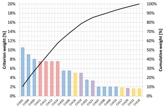
Figure 2.
Ranking of compound weights for design criteria (Pareto chart). Criteria highlighted according to related functional requirement: F1 → blue, F2 → red, F3 → yellow, F4 → purple.
2.4. Evaluation Method
The concept search, detailed further in the next section, is structured stepwise in five iterative stages: (a) identification, (b) classification, (c) screening, (d) inter-comparison, and (e) evaluation. Additionally, design trade-offs and variants are considered. The aim is to select a few favorite design candidates, which are compatible for an efficient operation of PEC(-PV) devices.
First, a design concept brainstorming based on a scientific and technical literature review allowed the identification of about 30 primary solar concentrator design concepts. These identified concepts were then classified into subgroups, according to the motional degrees of freedom of the optical tracking system, versus the PEC(-PV) device motional degrees of freedom. A preliminary screening of classified concepts based on the assessment of technological complexity and maturity allowed filtering a shorter list of relevant design candidates. For these selected concepts, geometrical configuration variants were taken into account for a preliminary geometrical analysis without detailed layout, based on 1-min sampled DNI data in Seville, Spain, obtained from CAMS radiation service [43] for the year 2019 (Appendix A, Figure A1 and Figure A2), an accurate astronomical solar position algorithm [44], angular nomenclature and geometrical equations for solar tracking surfaces [45] (Appendix B, Table A1), and defined PEC(-PV) device orientation and tilt constraints (Figure 1c).
Short-listed design concepts were then compared against each other and evaluated for each formulated design criterion, applying a similar method as outlined in Table 1 for the cross-comparison and grading concepts according to a subjective scale outlined in Table 2, taking into account their relative ranking. Individual design criterion scores were compiled and weighted into an evaluation matrix for each design concept. Finally, the three best ranked candidates were reviewed to suggest potential design trade-offs and variants.
Table 2.
Grading scale and qualitative interpretation.
3. Concept Search
3.1. Identification and Classification
Identified solar concentrator design concepts could be classified along two dimensions, segmented in three categories each, i.e., on the one hand optical tracking system degrees of freedom (categories: stationary, one-axis or two-axis) and on the other hand degrees of freedom for the PEC(-PV) device (categories: fix focus, translational or rotational motion). This two-dimensional classification matrix is shown in Table 3. It consists of nine subgroups, labelled from A to I. Design concepts documented in the literature could be sorted into seven subgroups, i.e., Subgroups A–D and G–I.
Table 3.
Classification matrix of concentrator design concepts identified during literature review.
3.1.1. Subgroup A
Subgroup A consists of elementary design concepts with static PEC(-PV) devices, combined with stationary optical surfaces. This subgroup includes a few configurations, such as V-shaped reflectors [46], compound parabolic collectors (CPC) [47], and stationary cylindrical troughs [48]. Although these concentrator concepts are simple and not expensive, they suffer from shortcomings such as low concentration factors, high inter-seasonal and intra-day variability, as well as dilution of radiation through multiple reflections. These concepts were not further deemed relevant candidates for primary concentrators, but could be viewed as building blocks for secondary optics. Luminescent Solar Concentrators (LSC) [49], which act as stationary light trap waveguides with a perpendicular target receiver area, were yet perceived at an early stage of development [50] and were thus not considered relevant for a simple and efficient combination with PEC(-PV) devices, although LSC technology allows utilizing both direct and diffuse solar radiation and a promising adoption for photochemistry has been demonstrated [51].
3.1.2. Subgroup B
Subgroup B includes some design concepts with stationary PEC(-PV) devices at a fix focus target line, combined with one-axis horizontal tracking optics for concentration, such as Linear Fresnel Reflectors (LFR) [52], which can be made more compact (C-LFR [53]) and also enhanced with Etendue-Matching (CLFR-EM [54]). LFR concepts hybridized with parabolic troughs, such as semi-parabolic LFR (SPLFR [55]) or fix-focus line parabolic troughs (FF-PT [56,57]) were also found in the literature. Keeping a static line of PEC(-PV) devices at the focus of such concentrators is a key advantage for these design concepts. These concentrators also offer satisfactory concentration ratios above 20 for the given application. This set of concepts may however suffer from a combination of optical losses (Crit07–10) and require a certain optimization effort to improve the trade-off between concentrated flux spatial uniformity and spillage with respect to the active area of PEC(-PV) devices mounted at the focal line.
3.1.3. Subgroup C
Subgroup C includes a few design concepts with static PEC(-PV) devices combined with two-axis tracking optics, such as PEC(-PV) devices mounted on solar tower with a surrounding heliostat field [58], point focusing Fresnel lens or paraboloid dish concentrators coupled with fiber optics [59,60], transmitting solar radiation via flexible waveguides to PEC(-PV) devices. These design concepts offer highest concentration factors, easily adjustable with a suitable target offset. Solar tower configurations offer higher optical efficiency, at the cost of additional complexity for the heliostat field layout and requiring higher land coverage than line focusing concepts in Subgroup B for the same quantity of PEC(-PV) devices. Point focusing concentrators coupled with fiber optics represent an elegant approach, as it virtually allows decoupling PEC(-PV) devices from the concentrator focus. However, these design concepts remain yet experimental and expensive for the given application scale deployment.
3.1.4. Subgroup D
Subgroup D includes design concepts coupling stationary optics with PEC(-PV) devices in translational motion, such as roof-mounted point or line-focusing Fresnel lenses coupled with PEC(-PV) devices, mounted on pulley cables [61]. These concepts would show certain inter-seasonal and intra-day variability in system output. These configurations may be satisfactory for small-scale building integrated home systems (Table 2), with roof-mounted Fresnel lenses [62] and indoor PEC(-PV) devices, but reveal less practicable for large scale systems such as the refueling or industrial stations, due to the required flexible piping length.
3.1.5. Subgroup G
Only a design concept could be classified in Subgroup G, i.e., the Fixed Mirror Solar Concentrator (FMSC [63]), where a stationary cylindrical concentrator with segmented reflector facets is coupled with a target receiver rotating on a defined orbit. However, this configuration does not seem to offer any advantage for an efficient coupling with PEC(-PV) devices, with respect to any defined design criterion.
3.1.6. Subgroup H
Subgroup H includes a set of design concepts combining one-axis horizontal tracking concentrators with rotating PEC(-PV) devices, such as parabolic or cylindrical troughs, with target mounted either parallel (CHAPS [64]) or nearly perpendicular (EUCLIDES [65]) to the aperture area, variants of the LFR concept, for example, an LFR island including a rotating platform with fixed reflectors for a daily adjustment of field orientation (NOLARIS solar island [66]) or one-axis tracking linear Fresnel lenses [67,68]. One-axis horizontal tracking trough configurations are common for solar concentrators, but field orientation and PEC(-PV) device tilt constraints have to be taken into account for the particular application. Additional shortcomings for one-axis tracking linear Fresnel lenses are the continuous lateral and vertical shifts of the lens focus line, thus generating a certain reduction of the concentration factor, inter-seasonal and intra-day variations, as well as considerable spillage, especially for a square PEC(-PV) device geometry.
3.1.7. Subgroup I
Subgroup I includes the broadest range of design concepts, coupling two-axis tracking optical concentrators with rotating PEC(-PV) devices. Solar concentrators consisting of two-axis parabolic or cylindrical troughs were published, with devices either mounted parallel [34,69,70] or perpendicular to the aperture plane. Two LFR variants were also identified, one with fixed mirrors mounted on a two-axis rotating platform with a target line parallel to the aperture plane [70,71], another one with a horizontal platform, with a variable field orientation and tracking reflectors, concentrating solar radiation on a target line perpendicular to the reflector horizontal aperture plane [66]. A broad range of Fresnel lens design concepts was also published [72], including two-axis tracking line or point [73,74] focusing lens arrays concentrating radiation on a target parallel to the lens aperture plane. Point focusing dishes [75] represent another option, albeit an expensive one as they allow only a few PEC(-PV) devices to be mounted per dish unit. All two-axis tracking concentrators coupled with rotating PEC(-PV) devices at the focus have the potential to offer the highest system efficiency, at the cost of an incremental system complexity.
3.2. Screening for Inter-Comparison
3.2.1. Short List of Design Concepts
A screening of solar concentrator design concepts identified in the previous stage is required to group similar concepts under a common label and extract a pool of relevant design options for a systematic concept inter-comparison and evaluation. Our short list consists of 12 candidates, outlined in Table 4. These concepts are schematically illustrated in the Appendix C (Figure A3).
Table 4.
Shortlist of design concepts for their inter-comparison.
3.2.2. Geometrical Configuration
Shortlisted design concepts can be further categorized and specified according to tracking modes and PEC(-PV) device with respect to the optical aperture plane of the concentrator. Geometrical configuration variants taken into account for the geometrical analysis at the reference site location are listed in Table 5. These configurations are illustrated in the Appendix D (Figure A4).
Table 5.
Description of geometrical configurations.
Geometrical configurations consist of: (a) Fix-focus LFR designs with vertically mounted PEC(-PV) devices, (b) one-axis horizontal tracking trough systems with PEC(-PV) devices mounted either perpendicular (b1–b2) or parallel (b3–b4) to the optical aperture plane, and (c) azimuth–elevation two-axis tracking systems with perpendicular (c1) or parallel (c2) PEC(-PV) devices. One-axis tracking systems are either tracking along an East–West (E-W) or North–South (N-S) axis. Intermediate solar field and PEC(-PV) device orientations are out of scope for this analysis. Further optical restrictions apply for FF-PT and LFL_1 design concepts. Tower systems were not included in the geometrical analysis because of the field layout complexity.
4. Results and Discussion
4.1. Geometrical Analysis
4.1.1. Reference Location
A geometrical analysis of the concept categories listed in Table 5 was performed assuming ideal concentrator geometries (i.e., neglecting tracking, shape, slope, dispersion, scattering, and bidirectional reflectance distribution function—BRDF—errors), taking into account trigonometric equations for tracking surfaces [45] for a system installed in Seville, Spain. This analysis was performed without drawing detailed three-dimensional concentrator layouts, which would be required for complementary raytracing analyses, in order to assess spatial flux distributions more accurately.
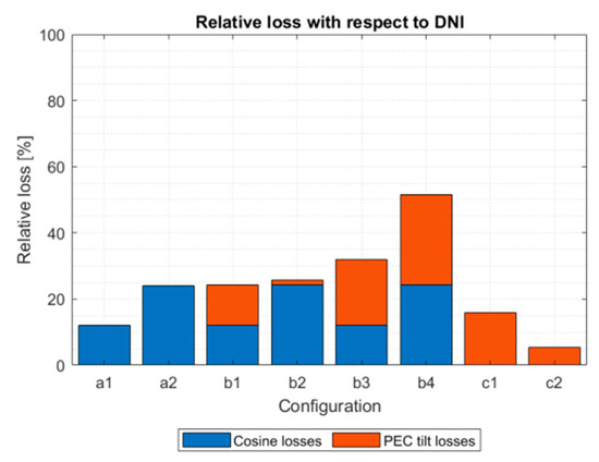
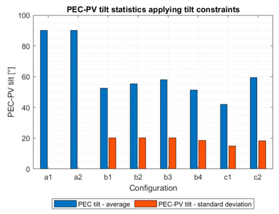
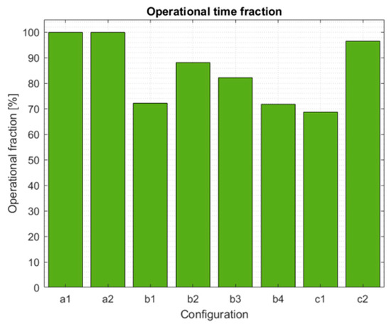
The geometrical analysis includes the following set of criteria: (a) maximum available DNI (kWh/m2), weighted by the incidence angle cosine and applying PEC(-PV) device tilt angle restrictions to discount corresponding non operational time windows, (b) monthly average (µ) direct normal irradiance weighted by incident angle cosine and yearly standard deviation (σ) for the assessment of yearly variability, (c) qualitative shape of the daily profile for the assessment of intra-day variability, (d) yearly incidence angle cosine losses with respected to the reference yearly DNI value (2300 kWh/m2/year), (e) losses due to PEC(-PV) device tilt restrictions (Figure 1c) with respect to yearly DNI, (f) PEC(-PV) device tilt angle statistics, excluding operational downtime induced by device tilt restrictions, and (g) operational time fraction (%). The main results of the geometrical analysis are summarized in Table 6 for Seville, Spain.
Table 6.
Summary of geometrical analysis for Seville, Spain.
Yearly variability statistics are shown in Figure 3 for all concepts, while monthly plots are included in the Appendix E (Figure A5). Intra-day variations of DNI.cos(θ) are also plotted (Figure A6). Cosine losses and PEC tilt losses are displayed in Figure 4. PEC tilt statistics are shown in Figure 5 while daily variations of the PEC(-PV) tilt device are shown in the Appendix E (Figure A5). Operational time fraction is shown in Figure 6.
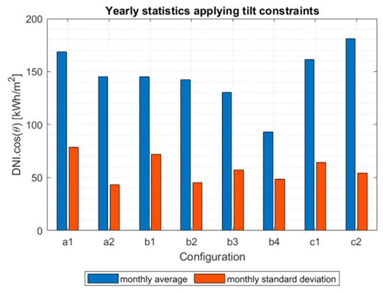
Two complementary configurations were compared for LFR designs with a fix focus line, i.e., (Config. a1) N-S field alignment with E-W reflector tracking and (Config. a2) E-W field alignment with N-S reflector tracking. Cosine losses were less significant for Config. a1 (−12%) than for Config. a2 (−24%), while both configurations were not penalized by device tilt constraints. As a result, more DNI could be harvested with Config. a1. Lower yearly variations are expected with Config. a2, but typical daily profiles exhibit a “bell” shape for Config. a2, while Config. a1 yields daily “M-shaped” profiles, with both peaks distributed symmetrically around solar noon.
Four configurations were compared for one-axis horizontal tracking trough systems. Config. b1 and b3 have both a similar geometrical layout as Config. a1, while Config. b2 and b4 are similar to Config. a2. Cosine losses are thus respectively similar between configurations a1, b1, b3 and between configurations a2, b2, and b4. Config. b1 and b3 daily profiles also exhibit typical “M-shaped” distributions, while Config. b2 and b4 daily profiles exhibit “bell” shapes.
PEC(-PV) device tilt constraints have to be taken into account to further assess these configurations. Minimal to moderate restrictions apply for Config. b1 and b2, where the PEC(-PV) device is perpendicular to the optical aperture.
Config. b2 shows minimal losses due to tilt constraints (−2%) and minimal yearly variability. Operational time is about 88% for Config. b2, with downtime occurring in the morning and evening hours during winter months for Seville, Spain. For Config. b1, higher losses due to tilt constraints are observed (−12%), along with higher yearly variability, lower daily variability, but a higher available solar radiation potential in comparison to Config. b2. Config. b1 is penalized by tilt restrictions all year round during morning and evening hours (operational time fraction: 72%).
For configurations with PEC(-PV) devices parallel to the aperture (b3, b4), tilt constraints are more severe. Config. b3 operation is reduced all year round around solar noon (operational time fraction: 82%), while Config. b4 operation is significantly reduced during summer months (operational time fraction: 72%).
One-axis horizontal tracking LFR systems with fix focus target lines are not penalized by PEC(-PV) device tilt constraints, contrary to one-axis horizontal tracking trough systems. Nonetheless, tangential and longitudinal IAM losses [76], as well as potential blocking and shading losses [77] further degrade the performance of LFR configurations, whereas trough configurations are only penalized by longitudinal IAM losses, which include cosine losses. IAM losses can be reduced both for LFR and trough design concepts adding a complementary tracking axis.
Two configurations (c1, c2) were compared for two-axis tracking systems with elevation–azimuth tracking mode. As the collector aperture plane is always oriented normal to the sun vector, these ideal configurations are not penalized by cosine losses. As a consequence, collected radiation is also nearly constant around solar noon for these configurations. Assuming clear sky conditions, minimal daily variability is expected for both configurations c1 and c2.
For Config. c1, operational hours are reduced all year round during the morning and evening hours. This configuration has the lowest operational time fraction (69%) and moderate yearly variations (σ/µ~40%). Losses due to tilt constraints remain however moderate (−16%). For Config. c2, operational hours are only reduced marginally in the summer around solar noon. This configuration shows a high operational time fraction (97%), minimal tilt losses (−5%) and minimal yearly variations (σ/µ~30%). As the PEC(-PV) device is parallel to the optical aperture, concentrated radiation is also always nearly perpendicular to the PEC(-PV) device, impinging with a normal angle on the device front window. Config. c1 and c2 thus emerge as dominant configurations from the geometrical analysis.
4.1.2. Influence of Site Location
The geometrical analysis carried out above for the reference location was transposed to two other locations in the Northern hemisphere at a lower latitude closer to the Equator, i.e., Ouarzazate, Morocco and Madinat Zayed, United Arab Emirates. Both sites are located in “sunny” regions near desert areas, weather data are retrieved from CAMS radiation service [43] for the year 2019. The geographical coordinates are summarized in Table 7. The relative losses with respect to DNI and the operational time fraction for both sites are, respectively, shown in Figure 7 and Figure 8.
Table 7.
Geographical coordinates and reference DNI of selected site locations.
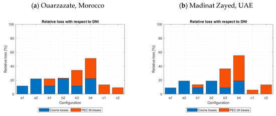
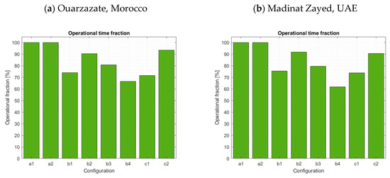
It is worth observing in Figure 7 and Figure 8 that the global hierarchy among all configurations, previously observed in Figure 4 and Figure 6, remains nearly identical for both sites closer to the Equator. However, minor differences can be noticed for Config. c1 and c2. As the latitude decreases, relative losses caused by PEC(-PV) tilt constraints are, respectively, decreasing for Config. c1 and increasing for Config. c2. Config. c2 still performed better than Config. c1 for Ouarzazate, but this was not the case for Madinat Zayed. A similar pattern can be observed for the operational time fraction, although Config. c1 still achieved the highest level. Numerical values are reported in Table 8 for both configurations.
Table 8.
Comparison of site locations for Configurations c1 and c2.
For Config. c2, the operational time fraction remains above 90% for a latitude of 23.6°. However, the operational hours are further reduced during the summertime around solar noon. This explains the drop in relative losses caused to PEC(-PV) tilt constraints. For Config. c1, the operational hours are extended all years round during the morning and evening. The relative losses are thus less pronounced in this case for lower latitudes.
4.2. Assessment of Spatial Flux Distribution
Spatial flux distribution of concentrated radiation on the PEC(-PV) device active area was defined as a key criterion (Crit01) for the selection of suitable concentrator design concepts, in addition to the geometrical aspects assessed in the previous section. Without performing raytracing analyses, this criterion was assessed on the basis of available literature for similar design concepts. Satisfactory design concepts should have a proven irradiance distribution uniformity over the cell plane within approx. ±20% of the average irradiance level.
Fix-focus LFR design concepts (LFR_1, CLFR-EM) could deliver satisfying spatial flux uniformity for flat or tubular receivers [55]. Potential design modifications include adjusting mirror widths, canting mirrors or defocusing mirrors, adding CPC or cylindrical secondary optics [78,79]. Nonetheless, varying mirror widths may impact blocking and shading losses, defocusing mirrors requires adjusting tracking settings for a ganged mirror field and secondary optics require reflector materials with excellent reflectance. Another option consists in adjusting the target line height and/or vertical tilt angle within tilt constraints, at the cost of a more complex piping system for the water and gas distribution system. Azimuth–elevation two-axis tracking LFR concepts (LFR-2), for example, with fixed reflectors mounted on an azimuth–elevation tracking platform, can achieve a spatial flux uniformity of ±5% and a concentration factor of 20 [70,71]. The additional system complexity associated with two-axis tracking LFR concepts may overcome required design trade-offs for one-axis horizontal tracking LFR systems with fix focus. However, significant spillage is expected if PEC(-PV) devices with a square active area are coupled with an LFR design concept.
Hybrid fix-focus trough concepts (SPLFR/FF-PT [55,56,57]), one-axis horizontal tracking trough (PT/CT_1a, PT_1b) as well as two-axis tracking trough systems (PT/CT_2a, PT_2b) do not generate optimally uniform spatial flux distributions. The flux distribution profile follows a typical “M-shaped” profile for flat and tubular receivers [55]. If PEC(-PV) devices are positioned perpendicular to the optical aperture plane (PT/CT_1a or PT/CT_1b), one optimization path is to adjust the parabolic cross-section to a cylindrical one [80], in order to focus radiation on a focal plane rather than a focal line, at the cost of a lower global concentration ratio. If PEC(-PV) devices are positioned parallel to the optical aperture plane (PT_1b, PT_2b), another optimization path is to adjust the distance between the target and the parabola vertex, although the irradiation distribution profile will not be as uniform as for an LFR design concept [55,70].
Design concepts based on two-axis tracking Fresnel lens arrays (LFL_2, PFLA) are the most suitable to achieve a highly uniform spatial flux distribution. For oblong PEC(-PV) active areas, flat or dome-shaped linear Fresnel lenses could concentrate solar radiation as well as azimuth–elevation two-axis tracking LFR systems [70,71], with minimal spillage. If the active areas approached a rather square shape, point focusing lens arrays would be best suited. Shifting the target along the focal line off the focal point allows improving flux uniformity (“spot” concentration) while reducing the global concentration ratio within a more suitable range for the PEC(-PV) device [73], without requiring secondary optics. Another option is to design a custom lens profile with multiple foci, so that concentrated irradiation is homogenously spread over a specified focal plane area [81] within ±20%.
4.3. Concept Evaluation: Scores and Ranking
Shortlisted design concepts were compared systematically for each formulated design criterion (Figure 2). Design concepts were ranked for each design criterion and assigned scores according to the scale defined in Table 2. These scores are weighted according to the defined weighting scheme (Table 1). Global scores and subscores are displayed in Figure 9 and ranked in Table 9.
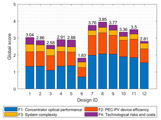
Figure 9.
Global score for each design concept listed in Table 4. The contribution of each functional requirement is displayed in each stacked bar.
Table 9.
Ranking of solar concentrator design concepts.
Three design concepts, i.e., the Point Focusing Lens Array (PFLA, Config. c2, rank #1), the two-axis tracked Linear Fresnel Reflector (LFR_2, Config. c2, rank #2) and the two-axis tracked Linear Fresnel Lens (LFL_2, Config. c2, rank #3) were evaluated as favorites during the systematic inter-comparison of solar concentrators. All three concepts almost achieved a score of 4.0 (“good”) for each functional requirement. These three concepts belong to the group of two-axis tracking Fresnel Reflector or Lens systems pooled in the geometrical configuration c2.
Two-axis concentrator tracking, combined with a parallel PEC(-PV) device to the optical aperture plane, offers both optimal concentrator optical performance and PEC(-PV) device efficiency. PFLA is considered as a favorite concept for cell geometries with a square active area, while LFR_2 or LFL_2 were considered most relevant for cell geometries with oblong, rectangular active areas. Secondary functional requirements, i.e., perceived system complexity, technological costs and risks are rated with lower scores than LFR or one-axis horizontal tracking trough concepts, although these three best design concepts were implemented in previous demonstration projects.
Two-axis tracking trough concepts (PT_2b, PT/CT_2a) are, respectively, ranked #4 and #5. One-axis tracking Linear Fresnel and trough concepts (LFR_1, PT/CT_1a, PT_1b, CLFR-EM) are ranked between #6 and #9. Non-uniform spatial flux distribution profiles make two-axis trough design concepts suboptimal for the given application, although the geometrical configuration (c1 or c2) rank among the best layouts according to the geometrical analysis. One-axis tracking design concepts (LFR_1, CLFR-EM, PT/CT_1a, PT_1b) would require a layout optimization in order to improve flux density and homogeneity and thus meet high performance requirements for the given water-splitting application. These concepts were thus deemed suboptimal during the inter-comparison.
The three worst design concepts were, respectively, the solar tower (rank #10), the hybrid fix-focus parabolic trough (rank #11) and one-axis tracking linear Fresnel lenses (#12). A solar tower configuration requires a more complex tracking strategy and field layout than one-axis tracking systems (LFR_1, CLFR-EM, PT/CT_2a, PT_2b) to drive the heliostat field on arrays of PEC(-PV) devices. A hybrid fix-focus trough (FF-PT) integrates both one-axis horizontal tracking LFR and trough advantages, but has a non-uniform spatial flux distribution; blocking and shading losses penalize this concept. One-axis tracking linear Fresnel lenses suffer from large variations in solar flux density at the focus over the day, depending on the sun incidence angle.
4.4. Design Trade-Offs and Variants
4.4.1. Material Selection
A few candidate optical component materials can be selected for the given water splitting application, considering the importance of harvesting all available solar radiation including the UV part effectively for most efficient PEC(-PV) device operation. Aluminum mirrors are the best choice for reflector materials, while second surface silvered glass mirrors are relevant in case of minor importance of the UV fraction for the PEC(-PV) performance. UV transparent PMMA, quartz or borosilicate glass may be suitable for refractive lenses [41]. UV-T PMMA is however less expensive than quartz or borosilicate glass and is easier to handle for the manufacturing of Fresnel lenses, using either traditional molding or innovative 3D printing [82] processes.
As aluminum reflectors and second surface silvered glass mirrors are more durable than UV transparent PMMA lenses, which suffer from yellowing, one could think of design variants for top ranking Fresnel lens-based design concepts, i.e., PFLA and LFL_2. From a geometrical perspective, modular two-axis tracking Ring Array [83] or Slat Array [84] concentrator design concepts could respectively substitute PFLA and LFL_2, although the marginal gained optical efficiency has to be balanced with higher material and manufacturing costs for polished aluminum surfaces and custom concentrator designs.
4.4.2. Secondary Optics
Reflective secondary optics, using either CPC [46], cylindrical troughs [48,80], kaleidoscope [82,85] or other non-imaging geometrical concepts [86] may further enhance solar concentrator performance by boosting the concentration ratio and homogenizing the spatial flux distribution across the PEC(-PV) device active area, at the cost of additional optical losses and material costs. Secondary optics coupled with two-axis tracking design concepts would be less penalized by multiple reflections, while reflective materials would be spectrally more efficient than refractive materials for secondary optics concentrators. Modular refractive point-focusing secondary optics may be a relevant design trade-off for line-to-spot conversion [87], allowing line focusing systems, (LFR_2, LFL_2) to concentrate solar radiation on square active areas.
5. Conclusions
This study focused on a review of solar concentrators and the selection of relevant design concepts for a coupling with tandem PEC(-PV) water splitting devices. Four main functional requirements were defined to guide the evaluation process for a coupled system: the concentrator optical performance, the resulting PEC(-PV) device efficiency, the system complexity and the technological costs and risks. A review of scientific and technical literature led to the identification of ~30 design concepts and variants, classified into 7 subgroups within a two-dimensional matrix, one dimension being the number of tracking axes for the optical concentrator, the other dimension describing the motion of the PEC(-PV) device.
Twelve design concepts, deemed relevant for a coupling with PEC(-PV) devices, were then shortlisted for a systematic inter-comparison. The shortlist included various options with complementary features, i.e., fix focus PEC(-PV) devices coupled to one-axis horizontal tracking linear Fresnel reflectors or hybrid trough systems, rotating PEC(-PV) devices coupled with one and two-axis tracking trough or line focusing Fresnel lens systems, two-axis tracking point focusing Fresnel lens and LFR systems, as well as fix focus PEC(-PV) devices mounted on a solar tower, surrounded by a heliostat field.
A geometrical analysis was carried out to assess the potential of various configurations, taking into account a few common tracking modes and PEC(-PV) device orientation with respect to the optical aperture plane. This geometrical analysis takes into account the PEC(-PV) tilt constraints. Satellite weather data for Seville, Spain, discretized with a one-minute time step for the year 2019 were combined with solar geometry equations for tracking surfaces. This quantitative analysis supported the rational assessment of important design criteria, such as inter-seasonal and intra-day variability of the available DNI resource, expected losses due to cosine effects or tilt restrictions, as well as operational time fraction for the given PEC(-PV) device tilt constraints. As a result, azimuth–elevation two-axis tracking concentrators with coupled PEC(-PV) devices represent a suitable geometrical configuration. This configuration would still achieve good results at other locations closer to the Equator, for latitudes above 25°, without significantly affecting the ranking of concentrator designs.
Complementary information was obtained from the literature review, to qualitatively assess design criteria such as IAM optical losses, spatial flux distribution of concentrated radiation on the active area and spillage, without detailed raytracing analyses. Two-axis tracking concentrators with PEC(-PV) devices oriented parallel to the optical aperture plane, were identified as the most promising concepts at this stage. Three concentrator design concepts emerged as favorites from the inter-comparison, i.e., (a) point-focusing Fresnel lens arrays for PEC(-PV) devices with square active areas, (b) azimuth–elevation Linear Fresnel Reflectors with fixed mirrors or (c) line-focusing Fresnel lenses for PEC(-PV) devices with an oblong, rectangular active area. Focal offset was identified as the simplest design modification to improve the spatial distribution of concentrated radiation flux, when the PEC(-PV) device was oriented parallel to the aperture plane of a two-axis tracking solar concentrator.
The results clearly show that tilt constraints of a PEC(-PV) device are significant parameters for the performance of water splitting powered by solar concentrators. Depending on the site location and the considered concentrator concept they lead to a certain down time, which reduces the usable fraction of the solar resource. Thus, tilt constraints of a PEC(-PV) device operated under concentrated sunlight have to be considered carefully in a detailed performance assessment.
This work represents an important guideline for future concentrator design studies. They should explore the techno-economical optimization potential of the proposed design concepts for medium concentration systems (C = 20–100) depending on the site location, the specific PEC(-PV) device active area geometry and tilt constraints. Detailed geometrical and system analysis, using raytracing and computational fluid dynamics (CFD) simulation tools, should allow the in depth investigation of the coupling of the PEC(-PV) device with the solar concentrator, focusing on the optimization of design aspects such as spatial and spectral flux distributions, cooling requirements and potential optical errors introduced by non-ideal concentrator geometries, i.e., the influence of common optical manufacturing and tracking errors.
Author Contributions
Conceptualization, M.W., M.R. and S.C.; methodology, S.C. and M.R.; software, S.C.; validation, S.C. and M.R.; formal analysis, S.C. and M.R.; investigation, S.C., MW. and M.R.; resources, S.C.; data curation, S.C.; writing—original draft preparation, S.C. and M.W.; writing—review and editing, S.C., M.W. and M.R.; visualization, S.C. and M.W.; supervision, M.R. and M.W.; project administration, M.W.; funding acquisition, M.W. All authors have read and agreed to the published version of the manuscript.
Funding
The authors would like to acknowledge the financial support of Europe’s Fuel Cell and Hydrogen Joint Undertaking (FCH JU) under Grant Agreement No. 621252 (PECDEMO).
Conflicts of Interest
The authors declare no conflict of interest. The funders had no role in the design of the study; in the collection, analyses, or interpretation of data; in the writing of the manuscript, or in the decision to publish the results.
Nomenclature
| Symbols | |
| C | Concentration ratio (-) |
| DNI | Direct Normal Irradiance (kWh/m2/year) |
| GHI | Global Horizontal Irradiance (kWh/m2/year) |
| Greek symbols | |
| αs | Solar altitude angle (°) |
| β | Slope (°) |
| γs | Surface azimuth angle (°) |
| δ | Declination (°) |
| θ | Incidence angle (°) |
| θz | Zenith angle (°) |
| μ | Monthly average (kWh/m2/month) |
| σ | Monthly standard deviation (kWh/m2/month) |
| φ | Latitude (°) |
| ω | Hour angle (°) |
| Subscripts | |
| 1 | One-axis tracking |
| 2 | Two-axis tracking |
| a | PEC(-PV) device perpendicular to aperture |
| b | PEC(-PV) device parallel to aperture |
| Acronyms | |
| CFD | Computational Fluid Dynamics |
| CLFR | Compact Linear Fresnel Reflector |
| CT | Cylindrical Trough |
| EM | Etendue Matching |
| E-W | East–West |
| FF | Fix Focus |
| IAM | Incidence Angle Modifier |
| LFL | Linear Fresnel Lens |
| LFR | Linear Fresnel Reflector |
| LSC | Luminescent Solar Concentrator |
| PEC | Photoelectrochemical |
| PFLA | Point Focusing Lens Array |
| PMMA | Poly-methyl-metacrylate |
| PT | Parabolic Trough |
| PV | Photovoltaics |
| NIR | Near Infrared |
| N-S | North–South |
| SPLFR | Semi-Parabolic Linear Fresnel Reflector |
| UV-T | Ultraviolet transparent |
Appendix A
The Direct Normal Irradiance (DNI) data for Seville, Spain [43] is plotted in Figure A1 and Figure A2.

Figure A1.
Direct Normal Irradiance (DNI) frequency distribution for Clear Sky and Actual Weather in Seville, Spain (Year: 2019).
Figure A1.
Direct Normal Irradiance (DNI) frequency distribution for Clear Sky and Actual Weather in Seville, Spain (Year: 2019).


Figure A2.
Heat map of yearly DNI distribution for Clear Sky and Actual Weather in Seville, Spain (Year: 2019).
Figure A2.
Heat map of yearly DNI distribution for Clear Sky and Actual Weather in Seville, Spain (Year: 2019).

Appendix B
The nomenclature is consistent with [45]. Relevant angles for tracking equations are listed here:
- -
- Latitudeφ, the angular location north or south of the equator, north positive; (−90° ≤ φ ≤ 90°).
- -
- Declinationδ, the angular position of the sun at solar noon w.r.t. the plane of the equator, north positive; (−23.45° ≤ δ ≤ 23.45°).
- -
- Slopeβ, the angle between the plane of the surface in question and the horizontal; (0° ≤ β ≤ 180°).
- -
- Surface azimuth angleγs, the deviation of the projection on a horizontal plane of the normal to the surface from the local meridian, with zero due south, east negative, and west positive; (−180° ≤ γs ≤ 180°).
- -
- Hour angleω, the angular displacement of the sun east or west of the local meridian due to rotation of the earth on its axis at 15° per hour; morning negative, afternoon positive.
- -
- Angle of incidenceθi, the angle between the beam radiation on a surface and the normal orientation to that surface.
- -
- Zenith angleθz, the angle between the vertical and the line to the sun, that is, the angle of incidence of beam radiation on a horizontal surface.
- -
- Solar altitude angleαs, the angle between the horizontal and the line to the sun, that is, the complement of the zenith angle (90° − θz).
The PEC-PV tilt (θPEC) is defined with respect to the collector slope β. For Config. a1 and a2, a transversal incidence angle θtrans is also introduced [2].
Table A1.
Tracking equations.
Table A1.
Tracking equations.
| Configuration | Equation | Ref |
|---|---|---|
| a1 | [88] | |
| a2 | [88] | |
| b1, b3 | [45] | |
| b2, b4 | [45] | |
| c1, c2 | [45] | |
Appendix C
Design concepts considered in this paper are illustrated in Figure A3.

Figure A3.
Illustration of design concepts listed in Table 4.
Figure A3.
Illustration of design concepts listed in Table 4.

Appendix D

Figure A4.
Illustration of geometrical configurations listed in Table 5.
Figure A4.
Illustration of geometrical configurations listed in Table 5.

Appendix E
Detailed results of the geometrical analysis are illustrated for Seville, Spain in Figure A5, Figure A6 and Figure A7.

Figure A5.
Yearly variation of DNI.cos(θ) in kWh/m2 for all geometrical configurations listed in Table 5, applying actual weather data and PEC(-PV) tilt constraints (20°–90°), where relevant. Site: Seville, Spain.
Figure A5.
Yearly variation of DNI.cos(θ) in kWh/m2 for all geometrical configurations listed in Table 5, applying actual weather data and PEC(-PV) tilt constraints (20°–90°), where relevant. Site: Seville, Spain.


Figure A6.
Intra-day variability on solstices and equinoxes of DNI.cos(θ) in W/m2 for all geometrical configurations listed in Table 5, under clear sky conditions, without applying PEC-PV tilt constraints. Site: Seville, Spain.
Figure A6.
Intra-day variability on solstices and equinoxes of DNI.cos(θ) in W/m2 for all geometrical configurations listed in Table 5, under clear sky conditions, without applying PEC-PV tilt constraints. Site: Seville, Spain.


Figure A7.
Intra-day PEC-PV tilt distributions on solstices and equinoxes for all geometrical configurations (except a1 and a2) without applying tilt constraints. The lower tilt threshold (20°) is represented as a black dotted line. Site: Seville, Spain.
Figure A7.
Intra-day PEC-PV tilt distributions on solstices and equinoxes for all geometrical configurations (except a1 and a2) without applying tilt constraints. The lower tilt threshold (20°) is represented as a black dotted line. Site: Seville, Spain.

References
- Velazquez Abad, A.; Dodds, P.E. Production of Hydrogen. In Encyclopedia of Sustainable Technologies; Abraham, M.A., Ed.; Elsevier: Oxford, UK, 2017; pp. 293–304. [Google Scholar] [CrossRef]
- Ball, M.; Weeda, M. The hydrogen economy—Vision or reality? Int. J. Hydrogen Energy 2015, 40, 7903–7919. [Google Scholar] [CrossRef]
- Tremel, A.; Wasserscheid, P.; Baldauf, M.; Hammer, T. Techno-economic analysis for the synthesis of liquid and gaseous fuels based on hydrogen production via electrolysis. Int. J. Hydrogen Energy 2015, 40, 11457–11464. [Google Scholar] [CrossRef]
- Lewis, N.S.; Nocera, D.G. Powering the planet: Chemical challenges in solar energy utilization. Proc. Natl. Acad. Sci. USA 2006, 103, 15729–15735. [Google Scholar] [CrossRef] [PubMed]
- Van de Krol, R.; Grätzel, M. Photoelectrochemical Hydrogen Production, 1st ed.; Springer: New York, NY, USA, 2012. [Google Scholar] [CrossRef]
- Koumi Ngoh, S.; Njomo, D. An overview of hydrogen gas production from solar energy. Renew. Sustain. Energy Rev. 2012, 16, 6782–6792. [Google Scholar] [CrossRef]
- Hanley, E.S.; Deane, J.P.; Gallachóir, B.Ó. The role of hydrogen in low carbon energy futures—A review of existing perspectives. Renew. Sustain. Energy Rev. 2018, 82 Pt 3, 3027–3045. [Google Scholar] [CrossRef]
- Rodriguez, C.A.; Modestino, M.A.; Psaltis, D.; Moser, C. Design and cost considerations for practical solar-hydrogen generators. Energy Environ. Sci. 2014, 7, 3828–3835. [Google Scholar] [CrossRef]
- Modestino, M.A.; Haussener, S. An integrated device view on photoelectrochemical solar-hydrogen generation. Annu. Rev. Chem. Biomol. Eng. 2015, 6, 6–13. [Google Scholar] [CrossRef]
- Maljusch, A.; Wullenkord, M. Technoeconomic Analysis of PEC Water Splitting at Various Scales. In Advances in Photoelectrochemical Water Splitting: Theory, Experiment and Systems Analysis, 1st ed.; Tilley, S.D., Lany, S., van der Krol, R., Eds.; Royal Society of Chemistry: Cambridge, UK, 2018; pp. 266–284. [Google Scholar] [CrossRef]
- Sathre, R.; Scown, C.D.; Morrow, W.R.; Stevens, J.C.; Sharp, I.D.; Ager, J.W.; Walczak, K.; Houle, F.A.; Greenblatt, J.B. Life-cycle net energy assessment of large-scale hydrogen production via photoelectrochemical water splitting. Energy Environ. Sci. 2014, 7, 3264–3278. [Google Scholar] [CrossRef]
- Shaner, M.R.; Atwater, H.A.; Lewis, N.S.; McFarland, E.W. A comparative technoeconomic analysis of renewable energy production using solar energy. Energy Environ. Sci. 2016, 9, 2354–2371. [Google Scholar] [CrossRef]
- Rothschild, A.; Dotan, H. Beating the Efficiency of Photovoltaics-Powered Electrolysis with Tandem Cell Photoelectrolysis. ACS Energy Lett. 2017, 2, 45–51. [Google Scholar] [CrossRef]
- Jacobsson, T.J.; Fjällström, V.; Edoff, M.; Edvinsson, T. Sustainable solar energy production: From photo-electrochemical cells to PV-electrolyzers and back again. Energy Environ. Sci. 2014, 7, 2056–2070. [Google Scholar] [CrossRef]
- Acar, C.; Dincer, I. Experimental investigation and analysis of a hybrid photoelectrochemical hydrogen production system. Int. J. Hydrogen Energy 2017, 42, 2504–2511. [Google Scholar] [CrossRef]
- Dumortier, M.; Tembhurne, S.; Haussener, S. Holistic design guidelines for solar hydrogen production by photoelectrochemical routes. Energy Environ. Sci. 2015, 8, 3614–3628. [Google Scholar] [CrossRef]
- Vilanova, A.; Lopes, T.; Spenke, C.; Wullenkord, M.; Mendes, A. Optimized photoelectrochemical tandem cell for solar water splitting. Energy Storage Mater. 2017, 13, 175–188. [Google Scholar] [CrossRef]
- Abdi, F.F.; Han, L.; Smets, A.H.M.; Zeman, M.; Dam, B.; van de Krol, R. Efficient solar water splitting by enhanced charge separation in a bismuth vanadate-silicon tandem photoelectrode. Nat. Commun. 2013, 4, 1–7. [Google Scholar] [CrossRef] [PubMed]
- Brillet, J.; Yum, J.-H.; Cornuz, M.; Hisatomi, T.; Solarska, R.; Augustynski, J.; Grätzel, M.; Sivula, K. Highly efficient water splitting by a dual-absorber tandem cell. Nat. Photonics 2012, 6, 824–828. [Google Scholar] [CrossRef]
- Tolod, K.R.; Hernández, S.; Russo, N. Recent advances in BiVO4 photocatalyst for sun-driven water oxidation: Top-performing photoanodes and scale-up challenges. Catalysts 2017, 7, 13. [Google Scholar] [CrossRef]
- Lee, W.J.; Shinde, P.S.; Go, G.H.; Ramasamy, E. Ag grid induced photocurrent enhancement in WO3 photoanodes and their scale-up performance toward photoelectrochemical H2 generation. Int. J. Hydrogen Energy 2011, 36, 5262–5270. [Google Scholar] [CrossRef]
- Turan, B.; Becker, J.-P.; Urbain, F.; Finger, F.; Rau, U.; Haas, S. Upscaling of integrated photoelectrochemical water-splitting devices to large areas. Nat. Commun. 2016, 7, 1–9. [Google Scholar] [CrossRef]
- Ahmet, I.Y.; Ma, Y.; Jang, J.-W.; Henschel, T.; Stannowski, B.; Lopes, T.; Vilanova, A.; Mendes, A.; Abdi, F.F.; van de Krol, R. Demonstration of a 50 cm2 BiVO4 tandem photoelectrochemical-photovoltaic water splitting device. Sustain. Energy Fuels 2019, 3, 2366–2379. [Google Scholar] [CrossRef]
- Monfort, O.; Raptis, D.; Satrapinskyy, L.; Roch, T.; Plesch, G.; Lianos, P. Production of hydrogen by water splitting in a photoelectrochemical cell using a BiVO4/TiO2 layered photoanode. Electrochim. Acta 2017, 251, 244–249. [Google Scholar] [CrossRef]
- Smirnov, V.; Welter, K.; Becker, J.P.; Urbain, F.; Jaegermann, W.; Finger, F. The Effect of the illumination intensity on the performance of Si multijunction based integrated photoelectrochemical water splitting devices. Energy Procedia 2016, 102, 36–42. [Google Scholar] [CrossRef]
- Njoka, F.; Ookawara, S.; Ahmed, M. Influence of the design and operating conditions on the performance of tandem photoelectrochemical reactors. Int. J. Hydrogen Energy 2018, 43, 1285–1302. [Google Scholar] [CrossRef]
- Wullenkord, M.; Jung, C.; Smirnova, O.; Sattler, C. Development of a novel solar photoelectrochemical tandem reactor with perforated photocathode for simultaneous hydrogen production and waste water treatment. In Proceedings of the ASME Power and Energy Conference, Lake Buena Vista, FL, USA, 24–28 June 2018. [Google Scholar] [CrossRef]
- Dumortier, M.; Haussener, S. Design guidelines for concentrated photo-electrochemical water splitting devices based on energy and greenhouse gas yield ratios. Energy Environ. Sci. 2015, 8, 3069–3082. [Google Scholar] [CrossRef]
- Haussener, S.; Hu, S.; Xiang, C.; Weber, A.Z.; Lewis, N.S. Simulations of the irradiation and temperature dependence of the efficiency of tandem photoelectrochemical water-splitting systems. Energy Environ. Sci. 2013, 6, 3605–3618. [Google Scholar] [CrossRef]
- Landman, A.; Dotan, H.; Shter, G.E.; Wullenkord, M.; Houaijia, A.; Maljusch, A.; Grader, G.S.; Rothschild, A. Photoelectrochemical water splitting in separate oxygen and hydrogen cells. Nat. Mater. 2017, 16, 646–651. [Google Scholar] [CrossRef]
- Segev, G.; Dotan, H.; Malviya, K.D.; Kay, A.; Mayer, M.T.; Grätzel, M.; Rothschild, A. High solar flux concentration water splitting with hematites (α-Fe2O3) photoanodes. Adv. Energy Mater. 2016, 6, 1–7. [Google Scholar] [CrossRef]
- Bicer, Y.; Dincer, I. Experimental investigation of a PV-coupled photoelectrochemical hydrogen production system. Int. J. Hydrogen Energy 2017, 42, 2512–2521. [Google Scholar] [CrossRef]
- Coelho, B.; Oliveira, A.C.; Mendes, A. Concentrated solar power for renewable electricity and hydrogen production from water—A review. Energy Environ. Sci. 2010, 3, 1398–1405. [Google Scholar] [CrossRef]
- Pinaud, B.A.; Benck, J.D.; Seitz, L.C.; Forman, A.J.; Chen, Z.; Deutsch, T.G.; James, B.D.; Baum, K.N.; Baum, G.N.; Ardo, S.; et al. Technical and economical feasibility of centralized facilities for solar hydrogen production via photocatalysis and photoelectrochemistry. Energy Environ. Sci. 2013, 6, 1983–2002. [Google Scholar] [CrossRef]
- Tembhurne, S.; Nandjou, F.; Haussener, S. A thermally synergistic photoelectrochemical hydrogen generator operating under concentrated solar radiation. Nat. Energy 2019, 4, 399–407. [Google Scholar] [CrossRef]
- Wullenkord, M.; Spenke, C.; Vilanova, A.; Lopes, T.; Mendes, A. PECDEMO Project Deliverable Report D6.4: Public Report on Performance of the Large Area Prototype Array. 2017. Available online: https://archiveweb.epfl.ch/pecdemo.epfl.ch/files/content/sites/pecdemo/files/public%20files/PECDEMO%20Deliverable%206.4_DLR_UPorto.pdf (accessed on 11 August 2020).
- Vilanova, A.; Dias, P.; Azevedo, J.; Wullenkord, M.; Spenke, C.; Lopes, T.; Mendes, A. Solar water splitting under natural concentrated sunlight using a 200 cm2 photoelectrochemical-photovoltaic device. J. Power Sources 2020, 454, 227890. [Google Scholar] [CrossRef]
- Sancho Ávila, J.M.; Riesco Martín, J.; Jiménez Alonso, C.; Sánchez de Cos Escuin, M.C.; Montero Cadalso, J.; López Bartolomé, M. Atlas de Radiación Solar en España Utilizando Datos del SAF de Clima de EUMETSAT; Agencia Estatal de Meteorología (AEMET): Madrid, Spain, 2012; Available online: https://www.aemet.es/documentos/es/serviciosclimaticos/datosclimatologicos/atlas_radiacion_solar/atlas_de_radiacion_24042012.pdf (accessed on 11 August 2020).
- Brey, J.J.; Brey, R.; Contreras, I.; Carazo, A.F. Roll-out of hydrogen fueling stations in Spain through a procedure based on data development analysis. Int. J. Hydrogen Energy 2014, 39, 4116–4122. [Google Scholar] [CrossRef]
- Baig, H.; Heasman, K.C.; Mallick, T.K. Non-uniform illumination in concentrating solar cells. Renew. Sustain. Energy Rev. 2012, 16, 5890–5909. [Google Scholar] [CrossRef]
- Miller, D.C.; Kempe, M.D.; Kennedy, C.E.; Kurtz, S.R. Analysis of transmitted optical spectrum enabling accelerated testing of multijunction concentrating photovoltaic designs. Opt. Eng. 2011, 50, 013003. [Google Scholar] [CrossRef]
- Royne, A.; Dey, C.J.; Mills, D.R. Cooling of photovoltaic cells under concentrated illumination: A critical review. Sol. Energy Mater. Sol. Cells 2005, 86, 451–483. [Google Scholar] [CrossRef]
- Qu, Z.; Oumbe, A.; Blanc, P.; Espinar, B.; Gesell, G.; Gschwind, B.; Klüser, L.; Lefevre, M.; Saboret, L.; Schroeter-Homscheidt, M.; et al. Fast radiative transfer parameterization for assessing the surface solar irradiance: The Heliosat-4 method. Meteorol. Z. 2016, 26, 33–57. [Google Scholar] [CrossRef]
- Blanc, P.; Wald, L. The SG2 algorithm for a fast and accurate computation of the Sun for multi-decadal time period. Sol. Energy 2012, 88, 3072–3083. [Google Scholar] [CrossRef]
- Duffie, J.A.; Beckman, W.A. Solar Engineering of Thermal Processes, 4th ed.; Part I: Fundamentals; Chapter 1: Solar Radiation; Duffie, J.A., Beckman, W.A., Eds.; Wiley: Hoboken, NJ, USA, 2013; pp. 3–41. [Google Scholar] [CrossRef]
- Reis, F. Development of Photovoltaic Systems with Concentration. Ph.D. Thesis, University of Lisbon, Lisbon, Portugal, 2013. [Google Scholar]
- Rabl, A. Comparison of solar concentrators. Sol. Energy 1976, 18, 93–111. [Google Scholar] [CrossRef]
- Nijegorodov, N.; Jain, P.K.; Devan, K.R.S. A non-tracking, cylindrical solar concentrator with circular cross-section: Theoretical and experimental analysis. Renew. Energy 1995, 6, 1–9. [Google Scholar] [CrossRef]
- Imenes, A.G.; Mills, D.R. Spectral beam splitting technology for increased conversion efficiency in solar concentrating systems: A review. Sol. Energy Mater. Sol. Cells 2004, 84, 19–69. [Google Scholar] [CrossRef]
- Tummeltshammer, C.; Taylor, A.; Kenyon, A.J.; Papakonstantinou, I. Losses in luminescent solar concentrators unveiled. Sol. Energy Mater. Sol. Cells 2016, 144, 40–47. [Google Scholar] [CrossRef]
- Cambié, D.; Dobbelaar, J.; Riente, P.; Vanderspikken, J.; Shen, C.; Seeberger, P.H.; Gilmore, K.; Debije, M.G.; Noël, T. Energy-efficient solar photochemistry with luminescent solar concentrator based photomicroreactors. Angew. Chem. Int. Ed. Engl. 2019, 58, 14374–14378. [Google Scholar] [CrossRef]
- Zhu, G.; Wendelin, T.; Wagner, M.J.; Kutscher, C. History, current state, and future of linear Fresnel concentrating solar collectors. Sol. Energy 2014, 103, 639–652. [Google Scholar] [CrossRef]
- Mills, D.R.; Morrison, G.L. Compact Linear Fresnel Reflector solar thermal powerplants. Sol. Energy 2000, 68, 263–283. [Google Scholar] [CrossRef]
- Chaves, J.; Collares-Pereira, M. Etendue-matched two-stage concentrators with multiple receivers. Sol. Energy 2010, 84, 196–207. [Google Scholar] [CrossRef]
- Zhu, J.; Huang, H. Design and thermal performances of Semi-Parabolic Linear Fresnel Reflector solar concentrating collector. Energy Convers. Manag. 2014, 77, 733–737. [Google Scholar] [CrossRef]
- Prahl, C.; Pfahl, A. A new concept for line-concentrating CSP collectors. In Proceedings of the SolarPACES Conference, Berlin, Germany, 15–18 September 2009; Available online: https://elib.dlr.de/61638/ (accessed on 11 August 2020).
- Prahl, C.; Schapitz, T.; Uhlig, R. Structural optimization of a line-focussing solar collector with stationary absorber tube. In Proceedings of the SolarPACES Conference, Granada, Spain, 20–23 September 2011; Available online: https://elib.dlr.de/72759/ (accessed on 11 August 2020).
- Lasich, J.; Thomas, I.; Hertaeg, W.; Shirley, D.; Faragher, N.; Erenstrom, S.; Carter, N.; Cox, B.; Zuo, Y. A 200 kW central receiver CPV system. AIP Conf. Proc. 2015, 1679, 030004. [Google Scholar] [CrossRef]
- Liang, D.; Fraser Monteiro, L.; Teixeira, M.R.; Fraser Monteiro, M.L.; Collares-Pereira, M. Fiber-optic solar energy transmission and concentration. Sol. Energy Mater. Sol. Cells 1998, 54, 323–331. [Google Scholar] [CrossRef]
- Feuermann, D.; Gordon, J.M.; Huleihil, M. Solar fiber-optic mini-dish concentrators: First experimental results and field experience. Sol. Energy 2002, 72, 459. [Google Scholar] [CrossRef]
- Sonneveld, P.J.; Swinkels, G.L.A.M.; van Tuijl, B.A.J.; Janssen, H.J.J.; Campen, J.; Bot, G.P.A. Performance of a concentrated photovoltaic energy system with static linear Fresnel lenses. Sol. Energy 2011, 85, 432–442. [Google Scholar] [CrossRef]
- Tripanagnostopoulos, Y.; Siabekou, C.; Tonui, J.K. The Fresnel lens concept for solar control of buildings. Sol. Energy 2007, 81, 661–675. [Google Scholar] [CrossRef]
- Pujol-Nadal, R.; Martinez-Moll, V. Parametric analysis of the curved slats fixed mirror solar concentrator for medium temperature applications. Energy Convers. Manag. 2014, 78, 676–683. [Google Scholar] [CrossRef]
- Coventry, J.S. Performance of a concentrating photovoltaic/thermal solar collector. Sol. Energy 2005, 78, 211–222. [Google Scholar] [CrossRef]
- Vivar, M.; Anton, I.; Pachon, D.; Sala, G. Third Generation EUCLIDES concentrator results. Prog. Photovolt. 2012, 20, 356–371. [Google Scholar] [CrossRef]
- Olcese, M.; Amorosi, S. The potential of new tracking methods combining the existing linear Fresnel collectors with the innovative Solar Island concept. In Proceedings of the SolarPACES Conference, Granada, Spain, 20–23 September 2011. [Google Scholar]
- Zhai, H.; Dai, Y.J.; Wang, R.Z.; Zhang, L.Y. Experimental investigation and analysis on a concentrating solar collector using linear Fresnel lens. Energy Convers. Manag. 2010, 51, 48–55. [Google Scholar] [CrossRef]
- Lin, M.; Sumathy, K.; Dai, Y.J.; Zhao, X.K. Performance investigation on a linear Fresnel lens solar collector using cavity receiver. Sol. Energy 2014, 107, 50–62. [Google Scholar] [CrossRef]
- Coventry, J.S. A Solar Concentrating Photovoltaic/Thermal Collector. Ph.D. Thesis, Australian National University, Canberra, Australia, 2004. [Google Scholar]
- Wullenkord, M.; Jung, C.; Sattler, C. Development of a concentrator with a rectangular flat focus used for hydrogen production via photocatalytic water splitting employing solar radiation. In Proceedings of the ASME 2012 6th International Conference on Energy Sustainability Collocated with the 10th International Conference on Fuel Cell Science, Engineering & Technology, San Diego, CA, USA, 23–26 July 2012; Available online: https://elib.dlr.de/80526/ (accessed on 11 August 2020).
- Wullenkord, M.; Jung, C.; Sattler, C. Design of a concentrator with a rectangular flat focus and operation with a suspension reactor for experiments in the field of a photovoltaic water splitting. In Proceedings of the ASME 2014 8th International Conference on Energy Sustainability Collocated with the ASME 2014 12th International Conference on Fuel Cell Science, Engineering and Technology, Boston, MA, USA, 30 June–2 July 2014; Available online: https://elib.dlr.de/91752/ (accessed on 11 August 2020).
- Xie, W.T.; Dai, Y.J.; Wang, R.Z.; Sumathy, K. Concentrated solar energy applications using Fresnel lenses: A review. Renew. Sustain. Energy Rev. 2011, 15, 2588–2606. [Google Scholar] [CrossRef]
- Huang, H.; Su, Y.; Gao, Y.; Riffat, S. Design analysis of a Fresnel lens concentrating PV cell. Int. J. Low Carbon Technol. 2011, 6, 165–170. [Google Scholar] [CrossRef][Green Version]
- Perharz, G.; Dimroth, F.; Wittstadt, U. Solar hydrogen production by water splitting with a conversion efficiency of 18%. Int. J. Hydrogen Energy 2007, 32, 3248–3252. [Google Scholar] [CrossRef]
- Kribus, A.; Kaftori, D.; Mittelman, G.; Hirshfeld, A.; Flitsanov, Y.; Dayan, A. A miniature concentrating photovoltaic and thermal system. Energy Convers. Manag. 2006, 47, 3582–3590. [Google Scholar] [CrossRef]
- Schenk, H.; Hirsch, T.; Feldhoff, J.F.; Wittmann, M. Energetic comparison of linear Fresnel and parabolic trough collector systems. J. Sol. Energy Eng. 2014, 136, 041015. [Google Scholar] [CrossRef]
- Sharma, V.; Nayak, J.K.; Kedare, S.B. Effects of shading and blocking in linear Fresnel reflector field. Sol. Energy 2015, 113, 114–138. [Google Scholar] [CrossRef]
- Mathur, S.S.; Kandpal, T.C.; Negi, B.S. Optical design and concentration characteristics of linear Fresnel reflector solar concentrators—II. Mirror elements of varying width. Energy Convers. Manag. 1991, 31, 205–219. [Google Scholar] [CrossRef]
- Mathur, S.S.; Kandpal, T.C.; Negi, B.S. Optical design and concentration characteristics of linear Fresnel reflector solar concentrators—II. Mirror elements of equal width. Energy Convers. Manag. 1991, 31, 221–232. [Google Scholar] [CrossRef]
- Taneja, P.; Mathur, S.S.; Kandpal, T.C. Optical performance evaluation of a circular cylindrical solar concentrator using different absorber shapes. Appl. Opt. 1991, 30, 1735–1740. [Google Scholar] [CrossRef]
- Ryu, K.; Rhee, J.-G.; Park, K.-M.; Kim, J. Concept and design of modular Fresnel lenses for concentrating solar PV system. Sol. Energy 2006, 80, 1580–1587. [Google Scholar] [CrossRef]
- Van Dijk, L.; Pepijn Marcus, E.A.; Jolt Oostra, A.; Schropp, R.E.I.; di Vece, M. 3D-printed concentrator arrays for external light trapping on thin film solar cells. Sol. Energy Mater. Sol. Cells 2015, 139, 19–26. [Google Scholar] [CrossRef]
- Lucent Optics, Ring-Array Optical Concentrator. Available online: http://www.lucentoptics.com/ring-array (accessed on 11 August 2020).
- Lucent Optics, Slat-Array Optical Concentrator. Available online: http://www.lucentoptics.com/slat-array (accessed on 11 August 2020).
- Ries, H.; Gordon, J.M.; Lasken, M. High-flux photovoltaic solar concentrators with kaleidoscope-based optical designs. Sol. Energy 1997, 60, 11–16. [Google Scholar] [CrossRef]
- Winston, R.; Miñano, J.C.; Benitez, P.; Shatz, N.; Bortz, J.C. Nonimaging Optics, 1st ed.; Elsevier Academic Press: Amsterdam, The Netherlands, 2005. [Google Scholar] [CrossRef]
- Ramirez, C.; Leon, N.; Garcia, H.; Aguayo, H. Optical design of two-axes parabolic trough collector and two-section Fresnel lens for line-to-spot solar concentration. Opt. Express 2015, 23, A480–A492. [Google Scholar] [CrossRef]
- Feldhoff, J.F. Linear Fresnel Collectors: A Technology Overview. In Proceedings of the SFERA Summer School, Almeria, Spain, 28 June 2012; Available online: http://sfera.sollab.eu/downloads/Schools/Fabian_Feldhoff_Linear_Fresnel.pdf (accessed on 11 August 2020).


© 2020 by the authors. Licensee MDPI, Basel, Switzerland. This article is an open access article distributed under the terms and conditions of the Creative Commons Attribution (CC BY) license (http://creativecommons.org/licenses/by/4.0/).