1. Introduction
With the increase in the demand for power, liquid nitrogen-cooled high-temperature superconducting (HTS) power cables (−196 °C, 77 K) are being actively developed as an eco-friendly alternative to conventional power transmission cables; these cables offer almost no electrical resistance and can transfer five to six times more power than existing power cables [
1,
2]. At the same time, with tightening emission regulations around the globe, the importance of natural gas as an eco-friendly fuel is increasing. While liquefied natural gas (LNG) is expected to emerge as a major energy source by 2035, it needs to be stored and transported at 110 K (−163 °C) [
3]. Therefore, the compound annual growth rate of the global cryogenic market is expected to increase (6.4% between 2020 and 2025). Specifically, the market for liquid nitrogen is expected to grow by up to 5.6%, and the highest growth is expected to be 7.8% for the LNG-related market [
4].
Liquid nitrogen is circulated inside HTS power cables to keep them at a temperature below 77 K (−196 °C). In the process, the liquid nitrogen is heated due to the external atmosphere, as well as the heat load from the current-carrying HTS power cable. Hence, a cooling system for subcooling the heated liquid nitrogen becomes essential; that is, a reverse Brayton cryogenic system that can cool several kilometers of HTS power cable is required. Therefore, high-efficiency reverse Brayton cryogenic systems with long maintenance cycles are being actively studied by researchers [
5,
6]. In Korea, the 23 kV 50 MVA one-km HTS power cable system for commercialization and the 154 kV 600 MVA one-km HTS power cable for demonstration used the several kW class reverse Brayton cryogenic system. Further, the 12 kV 72 MVA two-km HTS power cable system in the US will use the 10 kW class reverse Brayton cryogenic system.
LNG, stored at approximately 110 K (−163 °C) at atmospheric pressure, generates boil-off gas (BOG) owing to heat gain from the external atmosphere. BOG needs to be discharged, as it may affect the structural integrity of gas storage tanks if left unchecked owing to pressure rise. This is usually done by burning the BOG to control the pressure inside the storage tank. However, this leads to wastage of a precious commodity, as well as the direct release of emissions to the atmosphere. Hence, the reliquefaction of BOG is being actively studied by researchers [
7,
8]. Several techniques can be employed to reliquefy from BOG to LNG, such as cascade, single mixed refrigerant (SMR), propane precooled mixed refrigerant (C3MR), dual mixed refrigerant (DMR), and reverse Brayton process. Among the above reliquefaction systems, there is a significant interest in reverse Brayton cryogenic systems, which have demonstrated excellent energy efficiency and cooling capacity while requiring less installation space. Hence, significant research and development on the process and thermodynamics of reverse Brayton cryogenic systems has been carried out [
9,
10,
11].
Figure 1 shows the T-s diagram and schematic diagram of a reverse Brayton cryogenic system, as well as photographs of such systems by Air Liquide and Taiyo Nippon Sanso for reference. A typical reverse Brayton cryogenic system consists of a compressor for adiabatic compression (1 → 2), an after-cooler for removing the compression heat (2 → 3), a heat exchanger for isostatic cooling (3 → 4), a cryogenic turbo-expander for adiabatic expansion (4 → 5), a load heat exchanger for load heat absorption (5 → 6), and a heat exchanger for isostatic heating (6 → 1) [
12]. The main components of a reverse Brayton cryogenic system include a heat exchanger, compressor, and expander. Generally, a plate-fin heat exchanger, screw- or turbo-type compressor, and turbo-expander or compander (compressor and expander) are used in such systems.
Reverse Brayton cryogenic systems have been developed mainly by Linde (München, Germany), Air Liquide (Paris, France), Cryostar (Hésingue, France), and Taiyo Nippon Sanso (Shinagawa, Tokyo, Japan). The dual turbo-expander process, turbo-expander process, and open turbo-expander process have been developed and are already in use in BOG liquefaction systems for LNG vessels, small- and medium-sized onshore LNG liquefaction plants, and HTS power equipment cooling systems. Furthermore, the reverse Brayton cryogenic system is expected to be applied to medical devices and aerospace industries, as well as industries related to liquid hydrogen, which is emerging as another energy source of the future [
13,
14,
15].
In this paper, we describe the thermodynamic design and fabrication of a reverse Brayton cryogenic system with a cooling capacity of a 2 kW class at 77 K. Unlike conventional reverse Brayton systems, the proposed system uses a scroll compressor, which is easy to use, and a plate-type heat exchanger, which is inexpensive and easily available. We also discuss the performance test conducted on the system. We expect that this study will contribute to the design and operation of future reverse Brayton cryogenic systems in a HTS power cable system and BOG reliquefaction.
2. Design
Generally, neon, helium, or hydrogen is used as a refrigerant in reverse Brayton cryogenic systems. In this study, neon was selected as the working fluid because of the subcooling liquid nitrogen for the HTS power cable, its high system efficiency, and the ability to have a low turbo machine rotation speed owing to its relatively higher molecular weight [
16,
17]. To determine the thermodynamic parameters (temperature, pressure, enthalpy, entropy, etc.) of each point on the T-s diagram, the authors used REFPROP 10.0, which is a refrigerant property calculation program developed by the National Institute of Standards and Technology [
18].
The main parameters of the thermodynamic design of the reverse Brayton cryogenic system were selected as presented in
Table 1. To realize a cooling capacity of approximately 2.1 kW (at 77 K), the expansion ratio was set to 2, and the compressor efficiency, cryogenic turbo-expander efficiency, and heat exchanger effectiveness were selected in consideration of the component specifications. Generally, the higher the maximum pressure, the better the system efficiency. However, the maximum pressure was set to 1.05 MPa in this study in accordance with the High-Pressure Gas Safety Control Act in South Korea.
The node values of the reverse Brayton cryogenic system were designed as presented in
Table 2.
The mass flow rate, required power of the compressor, and the expansion power of the cryogenic turbo-expander (presented in
Table 3) were calculated using Equations (1)–(4):
where
is the cooling power,
is the mass flow rate,
h6 is the outlet enthalpy of the load heat exchanger, h
5 is the outlet enthalpy of the cryogenic turbo-expander,
is the power of the compressor,
h2 is the outlet enthalpy of the compressor,
h1 is the inlet enthalpy of the compressor,
εH is the heat exchanger effectiveness,
T1 is the outlet temperature of the low-pressure side of the heat exchanger,
T6 is the inlet temperature of the low-pressure side of the heat exchanger,
T3 is the inlet temperature of the high-pressure side of the heat exchanger,
is the power of the cryogenic turbo-expander,
h4 is the inlet enthalpy of the cryogenic turbo-expander, and
h5 is the outlet enthalpy of the cryogenic turbo-expander.
3. Construction and Testing
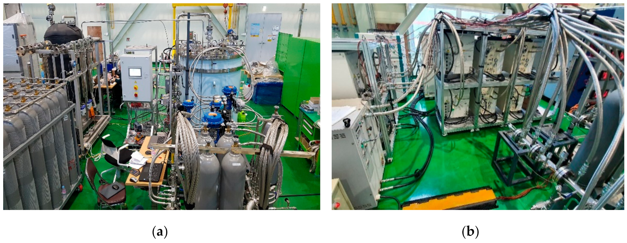
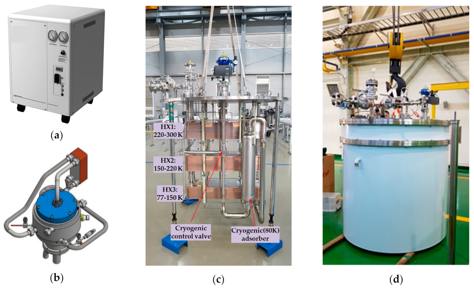
The specifications of the scroll compressor package (Sumitomo, Cryomech, and GVT); plate-type heat exchanger (SWEP); cryogenic turbo-expander (ATEKO); and cold box of the reverse Brayton cryogenic system used in this study are shown in
Figure 2, and their specifications are summarized in
Table 4. Generally, a screw- or turbo-type compressor is used to compress a low-pressure refrigerant into a high-pressure refrigerant. However, in this study, a helium scroll compressor was utilized, as it is widely used in the existing Gifford-McMahon cryocoolers. Several such compressors were connected in parallel based on the flow rate and pressures in the system design. Instead of using an off-the-shelf brazed aluminum plate-fin heat exchanger, we used a custom plate-type heat exchanger, which is cheaper, easily available, offers a high heat exchange volume, and achieves the target heat exchanger effectiveness (0.98). As an expander that reduced the temperature of the reverse Brayton cryogenic system by expanding a high-pressure refrigerant to a low-pressure one, we selected a cryogenic turbo-expander that is widely used in practice. This cryogenic turbo-expander was customized with gas bearings that can withstand long-term use [
19]. The cryogenic turbo-expander was configured to rotate at a rated speed of 88,000 rpm and exhaust the expansion work through an eddy current breaker (ECB). The compressor outlet pressure was set to be higher than the design pressure to meet the required specifications for the cryogenic turbo-expander gas bearings. An electric heater that can be used in a cryogenic environment was applied as the load for performance testing of the reverse Brayton cryogenic system, and a cold box to maintain a high vacuum for the cryogenic environment and a multilayer insulation to block the radiant heat were also utilized.
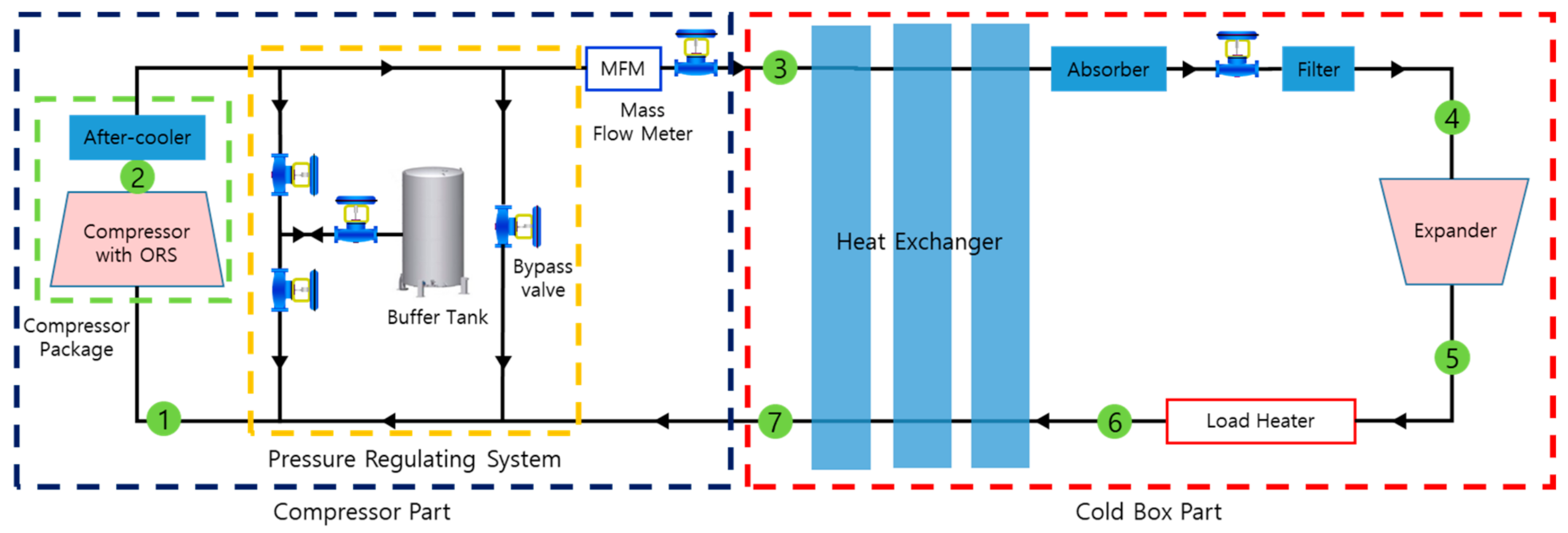
Figure 3 shows a schematic diagram of the proposed reverse Brayton cryogenic system. It is composed of (1) a compressor part consisting of a compressor package with an oil removal system (ORS) integrated with a water cooling-type after-cooler and a pressure regulating system (PRS); (2) a cold box part consisting of a heat exchanger and cryogenic turbo-expander; and (3) a PRS part, which consists of a buffer tank (1 m
3), bypass valve, make-up valve, and system high-pressure control valve, to maintain the pressure according to variations in the density.
Figure 4 shows the actual system that was fabricated. The compressor package consists of a compressor, an ORS, an after-cooler, and an adsorbent. The refrigerant is compressed under high temperature and high pressure by the compressor (which also separates the oil), is cooled down to room temperature by the after-cooler, passes through the adsorbent, goes through the PRS to prevent a system pressure change due to the temperature change, and is then supplied to the cold box while maintaining a constant pressure throughout. The system was configured as a closed-loop structure; the low-temperature, high-pressure refrigerant was decompressed by a cryogenic turbo-expander after passing through the heat exchanger. Then, it was cooled down to the target temperature, heated by the load heat exchanger, and finally, recirculated into the compressor after transferring the cold heat to the high-temperature, high-pressure refrigerant through the heat exchanger. Control valves for system pressure and flow control and safety valves for system safety were installed. A filter and an absorber were used to protect the cryogenic turbo-expander from rotating at a high speed at low temperatures. To measure the performance of the main components, we installed temperature and pressure sensors at the inlet and outlet of each component. A mass flow meter and a watt-hour meter for measuring the power requirements of the compressor were also installed. The system is controlled via programmable logic controllers (PLCs) and configured to save all data on a PC.
4. Measurement Results and Discussion
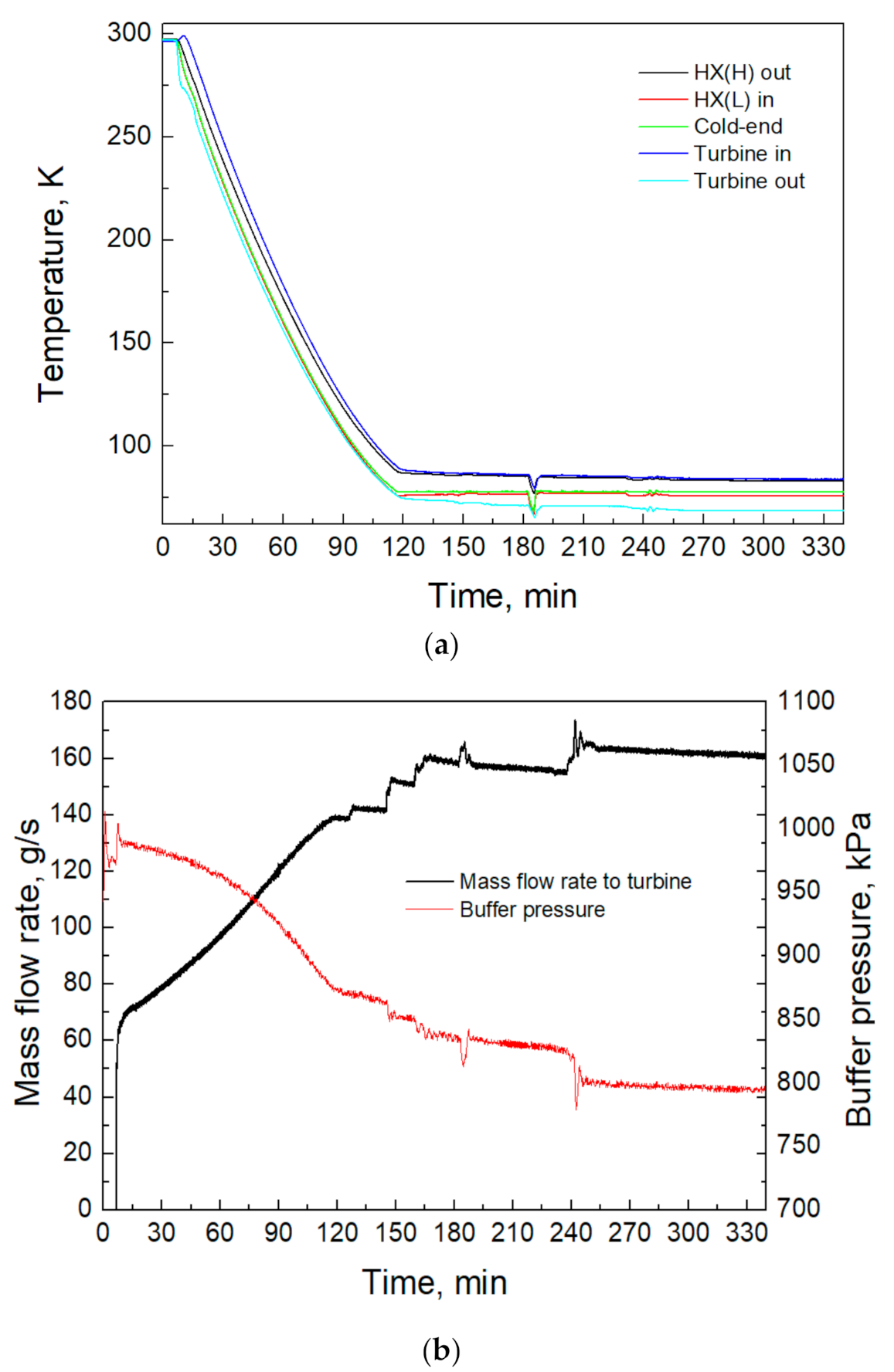
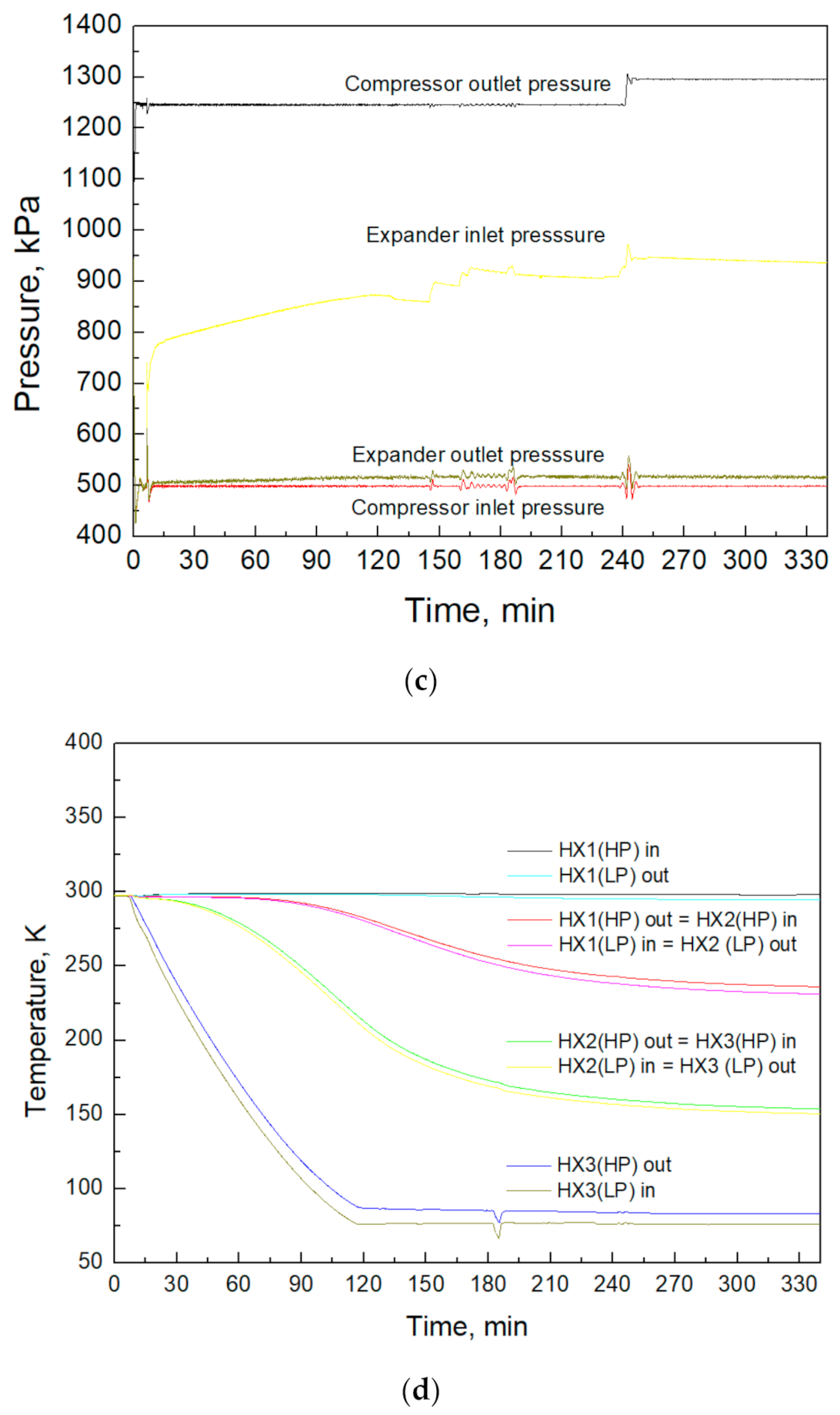
After performing several fill and purge operations to remove the impure gas inside the fabricated reverse Brayton cryogenic system, a cool-down performance test was conducted by modifying the control factor of the flow control valve, as shown in
Figure 5. The valves of the PRS were controlled to prevent pressure variations due to the decrease in the refrigerant temperature, which results in a decrease in the pressure inside the buffer tank and an increase in the refrigerant flow rate.
As the refrigerant flow rate increased, the system temperature decreased constantly, and the low-temperature part was cooled in 2 h. The low pressure of the system was controlled to approximately 0.5 MPa, and the high pressure was set to approximately 1.3 MPa to meet the gas-bearing pressure required by the turbo-expander. It seems that the inlet state of the turbo-expander changes with variations in the temperature and flow rate of the refrigerant. The heat exchanger is composed of three units: HX1 (220–300 K), HX2 (150–220 K), and HX3 (77–150 K). The high-pressure outlet and low-pressure inlet temperatures of the HX3 heat exchanger were cooled first and stabilized. The temperatures of the HX2 and HX1 heat exchangers required 3.5 h to cool down and stabilize, indicating that the thermal mass of the heat exchangers had a significant influence on the cool-down time of the system.
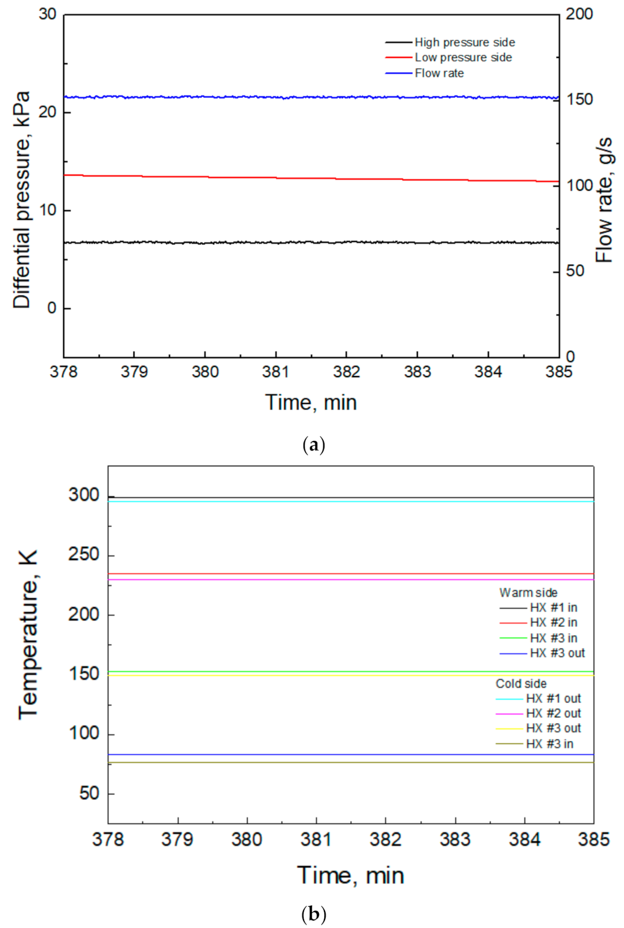
Figure 6 shows the heat exchanger status values during the performance test. The design refrigerant flow rate was 0.174 kg/s, but the refrigerant flow rate turned out to be approximately 0.152 kg/s due to limitations in the compressor’s capacity during the actual operation, converging at approximately 87% of the design level. To meet the target design refrigeration capacity, the refrigerant flow rate needs to be improved, and the compressor capacity should be increased. However, the scroll compressor can still be applied to the reverse Brayton cryogenic system. A normal and constant temperature was maintained at each inlet and outlet of the heat exchanger. The pressure drop on the high-pressure side was approximately 7 kPa on average, whereas the pressure drop on the low-pressure side was approximately 13 kPa on average. Therefore, it appears that the design specification (high-pressure side: 30 kPa or less and low-pressure side: 50 kPa) will be sufficiently satisfied even if the refrigerant flow rate rises to the design flow rate.
Table 5 presents the temperature difference at each inlet and outlet of the heat exchanger unit. HX3 and HX2 exhibited a higher temperature difference than the design specifications, whereas HX1 exhibited a lower temperature difference than the design specifications. As the effectiveness of the heat exchanger has a significant influence on the system performance, the heat exchanger effectiveness of the high- and low-pressure sides was calculated using Equations (5) and (6). The heat exchanger effectiveness of the low-pressure side was approximately 0.984, which is comparable to the design specification (0.98), whereas that of the high-pressure side was 0.968, which is lower than the design specification (0.98). When the refrigerant flow rate is increased, the effectiveness of the heat exchanger is expected to further decrease; hence, an improved design with an increased heat transfer area for the high-temperature heat exchanger (HX1) is needed. However, the plate-type heat exchanger can still be applied to the reverse Brayton cryogenic system.
where
εHL is the heat exchanger effectiveness of the low-pressure side,
is the mass flow rate,
h1 is the outlet enthalpy of the low-pressure side of the heat exchanger,
h6 is the inlet enthalpy of the low-pressure side of the heat exchanger,
h3 is the inlet enthalpy of the high-pressure side of the heat exchanger,
εHH is the heat exchanger effectiveness of the high-pressure side, and
h4 is the outlet enthalpy of the high-pressure side of the heat exchanger.
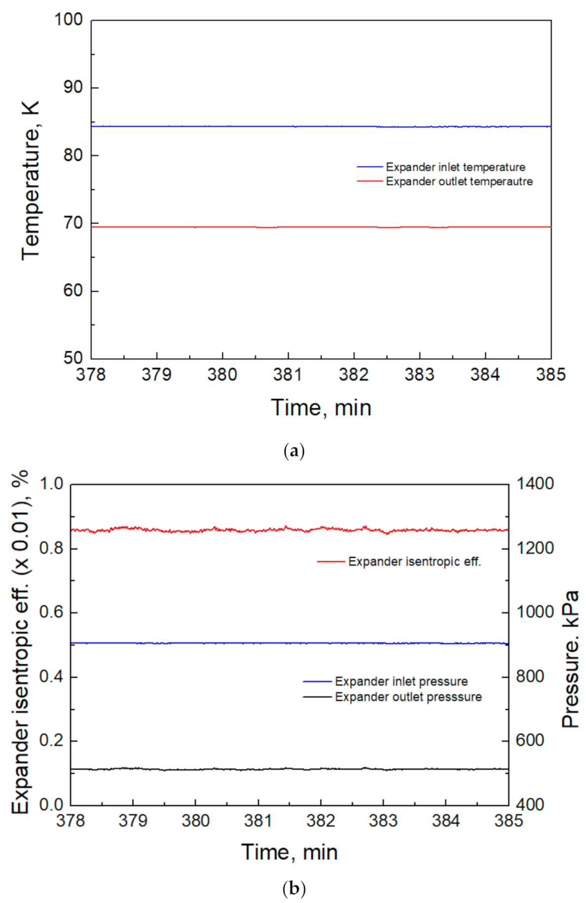
Figure 7 shows the temperature and pressure at the inlet and outlet of the cryogenic turbo-expander, and the isenthalpic efficiency of the cryogenic turbo-expander from the performance test at the target temperature (77 K). In the test, the temperature and pressure at the inlet and outlet of the cryogenic turbo-expander were kept constant. The pressure at the outlet of the turbo-expander was kept constant at approximately 0.5 MPa by setting the cryogenic turbo-expander. The pressure at the inlet of the turbo-expander was measured to be 0.1 MPa lower than the design specification owing to pressure loss by the absorber. The isentropic efficiency of the cryogenic turbo-expander was calculated using Equation (7) and found to be approximately 86%—higher than the design specification (78%).
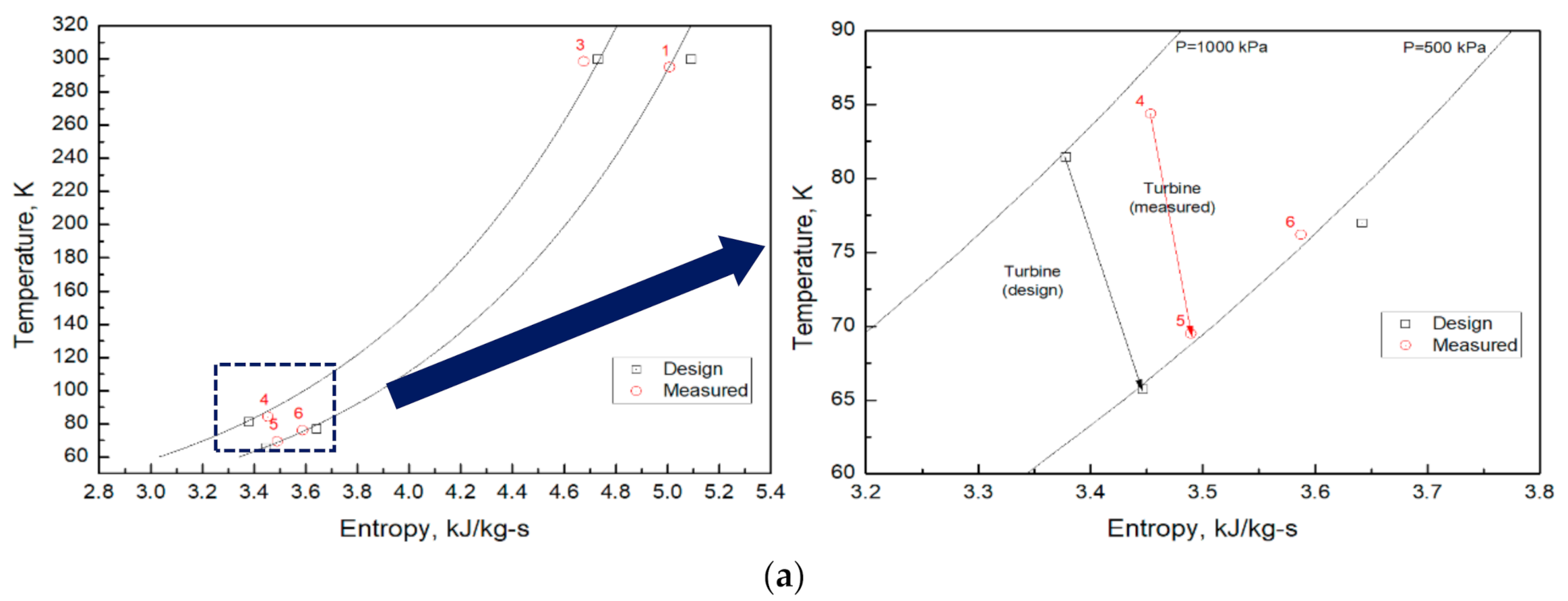
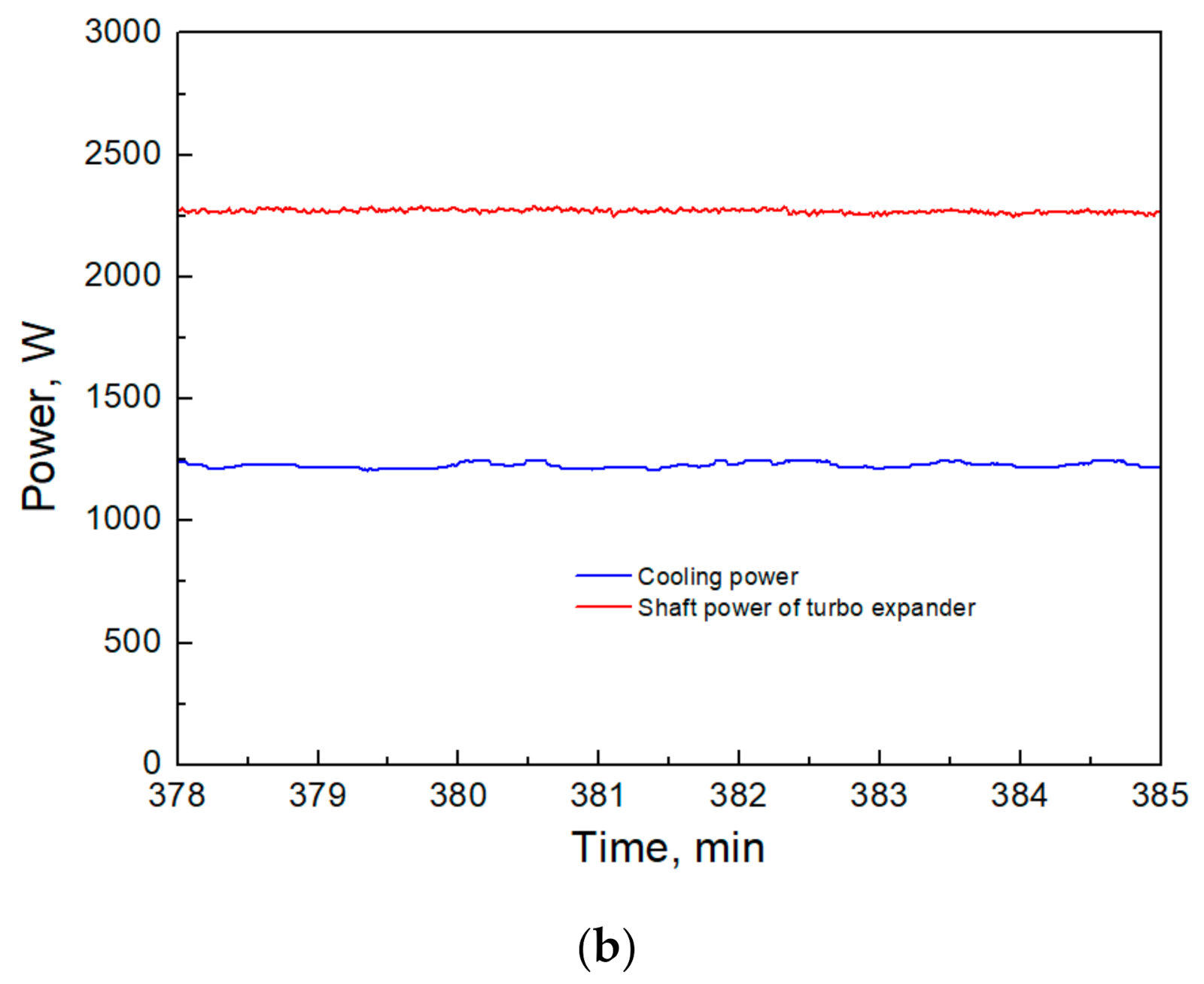
Figure 8 shows a comparison of the performance test results with the design specifications of the proposed system using a T-s diagram, as well as the shaft power and cooling power of the cryogenic turbo-expander over time. The slope of the adiabatic expansion (4 → 5) process indicates that the expansion efficiency was better than the design. The turbo-expander inlet pressure was measured to be lower than the design specification owing to the insufficient compressor capacity and pressure loss, and the outlet temperature of the high-pressure side of the heat exchanger was measured to be approximately 2.9 K higher than the design specification because of the decrease in the effectiveness of the heat exchanger. As a result, the temperature after expansion was measured to be approximately 3.8 K higher than the design specification. The shaft power of the cryogenic turbo-expander was calculated to be approximately 2179 W using Equation (8), and the cooling power was measured to be approximately 1229 W. Owing to the low-heat exchanger effectiveness,
/
was measured to be approximately 73% of the design level (approximately 78%).
where
εE is the isentropic efficiency of the cryogenic turbo-expander,
h4 is the inlet enthalpy of the cryogenic turbo-expander,
h5 is the outlet enthalpy of the cryogenic turbo-expander,
h5s is the outlet enthalpy of the turbo-expander at the ideal adiabatic expansion,
is the shaft power of the cryogenic turbo-expander, and
is the mass flow rate.
5. Conclusions
In this paper, a fabricated reverse Brayton cryogenic system comprising a scroll compressor, plate-type heat exchanger equipment, and a cryogenic turbo-expander is described after the thermodynamic design. The performance test conducted on the system is also described, and it was found that the cool-down of the reverse Brayton cryogenic system took approximately 5.5 h, wherein the thermal mass of the heat exchanger was found to be the main factor influencing this time. Additionally, the refrigerant flow rate turned out to be approximately 0.152 kg/s owing to the limitations of the capacity of the compressor during the actual operation, converging at approximately 87% of the design level. Hence, there is a need to improve the compressor capacity and efficiency. Further, the pressure drop of the heat exchanger was measured to be lower than that of the design; however, the heat exchanger effectiveness was low at the high-pressure side. Therefore, the heat transfer area of the high-pressure heat exchanger needs to be improved. The isentropic efficiency of the cryogenic turbo-expander was measured to be high at 86%. The compressor, heat exchanger, and turbo-expander used in this study were found to be suitable for application in the reverse Brayton cryogenic system. Although the cooling power of the reverse Brayton cryogenic system was calculated to be approximately 1.23 kW at 77 K instead of the targeted 2 kW class owing to the heat exchanger effectiveness, refrigerant flow rate, and pressure drop, it would be possible to implement a reverse Brayton cryogenic system with a 2 kW class refrigeration capacity through improvements in the design. Our results will not only contribute to the design and operation of reverse Brayton cryogenic systems of the future, they will also contribute to the faster commercialization of HTS power cables and more efficient storage of liquefied natural gas. Furthermore, this system is expected to contribute to the development of medical devices and the aerospace industry, as well as other industries related to liquid hydrogen.


