Article

Ripple Analysis and Suppression Method Research of Direct Drive Permanent Magnet Synchronous Wind Turbine under Wind Shear

1
School of Automation, Central South University, Changsha 410083, China
2
Hunan Xiangjiang Artificial Intelligence Academy, Changsha 410036, China
*
Authors to whom correspondence should be addressed.
Energies 2020, 13(19), 5088; https://doi.org/10.3390/en13195088
Submission received: 24 July 2020 / Revised: 19 September 2020 / Accepted: 23 September 2020 / Published: 29 September 2020
(This article belongs to the Section K: State-of-the-Art Energy Related Technologies)

Abstract

:
Wind shear is among the important sources of torque fluctuation on mechanical side and output power fluctuation on electromagnetic side and grid connection point, which frequency are triple turbine rotation frequency. With the increase in wind turbine single capacity and wind power integration scale, the power fluctuation caused by wind shear cannot be ignored. The paper takes a direct-drive permanent magnet synchronous wind turbine (PMSWT) as the research object. Firstly, the fluctuation transfer mechanism model is established; then, the current ripple is extracted by a notch filter to calculate the voltage control signal to suppress power fluctuation actively by the DC link capacitor which absorbs fluctuation energy. The simulation experiment shows that the suppression strategy is effective and reliable.

1. Introduction

Since wind speed increases with vertical height, the wind resource received by the wind turbine at a transient moment is not a constant value, which causes a series of problems related to wind shear [1,2,3,4]. Dale S. L. Dolan has completed the modeling of the output torque of a three-bladed wind turbine under wind shear, showing that wind shear causes 3p fluctuation and a small mean reduction in the output torque of the wind turbine [5]. When the generator is driven by the undulatory torque, the shaft speed and rotor speed of permanent magnet synchronous generator (PMSG) would be periodically fluctuating at 3p frequency as well [6]. Such forced fluctuation of wind turbine torque under wind shear would cause a series of power quality issues [7,8,9].
Focusing on those power quality issues, Roohollah Fadaeinedjad completed a comprehensive analysis by simulation in TurbSim and FAST, the analysis result shows that wind shear would cause 3p frequency periodic impacts in output power [10]; meanwhile, the periodic variation of terminal voltage exists as a voltage flicker in the three-phase, which is a great challenge when integrating wind energy into grid [11]. With the increase in wind power integration scale, the grid-connected point voltage stability issues in the high penetration power network become a highly concerning problem [12,13].
There have been many solutions regarding the power quality issues listed above, which basically can be classified into two categories: (1) damping control on the generator part; (2) adding a power storage device in a converter combined with a control strategy. Weihao Hu notices that by adding inverse oscillation to the rotor speed of the generator, the 3p frequency voltage flicker and active power fluctuation can be partly dampened [14]; yet considering the control strategy of permanent magnet synchronous wind turbine (PMSWT), the electromotive force feedback loop is related to rotor speed, which is the main reason for limiting the efficiency of dampening 3p frequency fluctuation. Shen Wang proposes a dampening method by installing an induction machine damping unit on the shaft of the generator to dampen the fluctuation of the shaft [15], but it has a lack of feasibility. Additionally, there is power storage equipment many researchers tend to add into the converter to store the undulatory power in case it flows into the grid and causes power quality issues. S. D. Gamini Jayasinghe proves that supercapacitors can mitigate the power fluctuation [16], but the additional supercapacitor would not work without an auxiliary inverter; similarly, the flywheel energy storage technology is used to smooth the power fluctuation injected to the grid [17]; however, both of them increase the cost and control complexity of the system. To avoid the extra cost, the inherent capacitor of the back-to-back converter is used to store the power fluctuation with no extra equipment [18].
In this paper, PMSWT with a dual-loop control under wind shear is selected as a research subject, and fluctuations or ripples caused by wind shear are summarized and modeled; the fluctuation transfer process and their frequency characteristics are analyzed. To achieve the ripple power storage in the capacitor, the current ripple in the DC link of is extracted by a notch filter, and based on the result of ripple extraction, a ripple control signal is added to the voltage loop of the grid side, which makes the voltage of the converter capacitor take the initiative to store the power fluctuation. The simulation results have proved the accuracy of the ripple analysis and the effectiveness of the ripple power storage strategy.

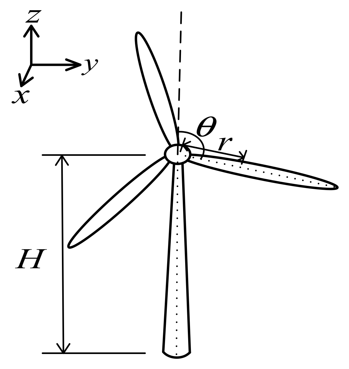
2. Transfer Mechanism Analysis of Fluctuation Caused by Wind Shear in PMSWT System

In this chapter, mathematical models are established, including generator-side models, PWM converters model, and the ripple transfer mechanisms of the wind shear from mechanical side to the grid connection point are analyzed.

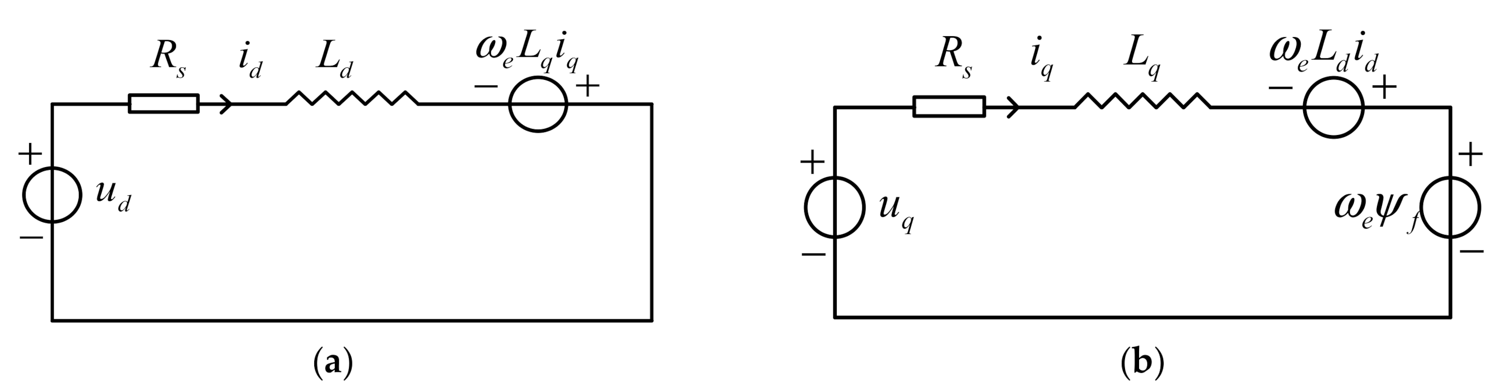
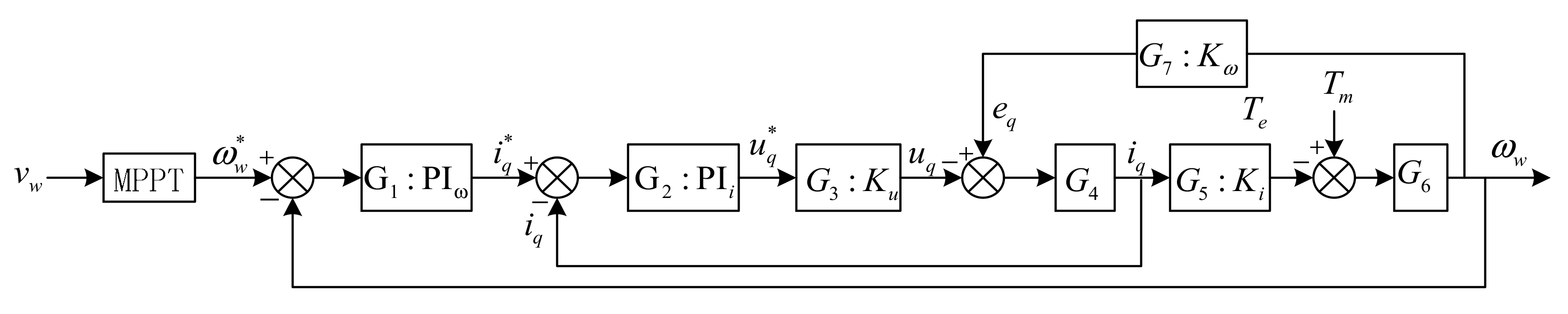
2.1. Ripple Analysis in Generator-Side

The variation tendency of wind speed in vertical height is generally described by an exponential function. Taking the wind speed V 0 at the hub height H as the reference, the wind speed V h at any height h takes the wind shear coefficient α as the index. According to the Momentum-Blade Element theory, the equivalent wind speed at the single blade is:
V r , θ = V 0 1 + r cos θ H α = V 0 1 + W r , θ W r , θ = α r H cos θ + α α 1 2 r H 2 cos 2 θ + α α 1 α 2 6 r H 3 cos 3 θ
In Equation (1), W r , θ is the wind shear function in three-order Taylor expansion, where cos 2 θ and cos 3 θ can be decomposed into polynomials with cos θ , cos 2 θ , and cos 3 θ ; r is the converted distance between the blade element and the hub; θ is the rotation azimuth. The parameters are shown in Figure 1.
When the PMSWT is running, the equivalent output torque under 3 blades is:
T m = 3 T 0 + n = 1 3 r 0 R δ r V r , θ n V 0 d r
In Equation (2), T 0 is the steady torque by V 0 ; r 0 is the distance between the blade root and the hub; R is the blade length; δ r is the influence coefficient of an aerodynamic load when the distance between the blade element and the hub is r ; n is the number of the blades. After superposition of wind shear effect of 3 symmetrical blades, the cos θ term is 0 and cos 2 θ is steady, but the cos 3 θ term fluctuates in equivalent wind speed. So, the wind shear causes periodic fluctuation of output torque T m , and the fluctuation frequency is 3 times the basis frequency of rotor speed (3p). T m can be expressed as:
T m t = T m c + A T t cos 3 ω w c t + θ T
In Equation (3), T m c is the steady component; A T t is the amplitude of the fluctuation component; ω w c is the rotor rotation frequency; θ T is the initial phase of the fluctuation torque component. Since the rotor of PMSG is rigidly connected with the shaft of the wind turbine, when PMSG is driven by the ripple torque, the rotor speed will be oscillated as well. The topology of the PMSWT system with dual-loop control strategy can be shown as following Figure 2:
In Figure 2, according to the detected wind speed v w , the maximum power point tracking (MPPT) module outputs a rotor speed command, which becomes the outer loop of the generator-side after comparing it with the actual rotor speed ω w . Meanwhile, the stator current in rotating coordinate forms the inner loop. The diagram of the generator-side of the PMSWT system is shown below:
In Figure 3, P I ω is the PI controller of the outer loop and its transfer function equals G 1 = K P ω + K I ω / s ; P I i is the PI controller of the inner loop and its transfer function equals G 2 = K P i + K I i / s ; K u is the gain of the rectifier; L s q is the q-axis line impedance of line connected to grid, G 4 represents the line impedance which equals 1 / s L s q + R s ; K i is the gain from stator current to electromagnetic torque of generator and it equals G 5 = 1.5 n p ψ f , ψ f is the flux linkage of the rotor, n p is the number of poles of PMSG; G 6 is 1 / s J , J is the inertia constant; K ω is the gain from rotor speed to q-axis inductive voltage and equals G 7 = n p ψ f ; T m is the output torque of wind turbine.
The PMSG is forced by the ripple torque component constantly, and the rotor speed command is from the MPPT module and is a constant value under a certain wind speed, so the rotor speed will be changing periodically. After the simplification of Figure 3, the transfer function between fluctuation torque and rotor speed in the complex frequency domain can be described as:
ω w s T m s = G 2 G 3 G 6 + G 2 2 G 3 2 G 4 G 6 G 1 G 2 2 G 3 2 G 4 G 5 G 6 + G 2 G 3 G 4 G 5 G 6 G 7 + G 2 G 3 + G 2 2 G 3 2 G 4
Similarly:
u q s T m s = G 1 2 G 2 2 G 3 G 6 G 1 G 2 + G 1 G 2 G 3 G 4 G 6 + G 4 G 6 G 1 G 2 G 5 1
According to Equations (3) and (4), the rotor speed is forced to oscillate periodically under wind shear. Since the transfer function can be regarded as a phase shift without affecting the frequency characteristic from the complex frequency domain to s domain, the rotor speed in this circumstance can also be written in the same form as Equation (3):
ω w t = ω w c + A ω t cos 3 ω w c t + θ ω
Similarly:
u q t = u q c + A u t cos 3 ω w c t + θ u
In Equation (6), A ω t is the amplitude of the rotor speed’s oscillation, θ ω is the initial phase of rotor speed oscillation which is effected by Equation (4) and θ T . In Equation (7), A u t is the amplitude of voltage oscillation, and θ u is the initial phase of voltage oscillation which is affected by Equation (5) and θ T .
Based on the equivalent circuit of PMSG shown in Figure 4, the d/q-axis current of the stator which represents the amplitude of stator AC under wind shear can be described in Equation (8).
L d d i d t d t = R s i d t + u d t + ω e t L q i q t L q d i q t d t = R s i q t + u q t ω e t L d i d t ω e t ψ f
In Equation (8), L d or L q is the equivalent inductance of PMSG in d or q-axis; in the same way, u d or u q is the equivalent terminal voltage in d or q-axis and is shown in Figure 3; i d or i q is the stator current in d or q-axis; ω e is the electrical angular speed, which equals n p ω w .
From Figure 2, the d-axis current of the stator can be considered as 0 in a dual-loop PMSWT system, so the d-axis current in the q-axis equation in Equation (8) can be ignored, and the rotor speed can be described as a sum of one steady component and one periodic component based on Equation (6); Equation (8) can be unfolded as:
L q d i q t d t = R s i q t + u q t n p ω w c ψ f n p A ω t ψ f cos 3 ω w c t + θ ω
In Equation (9), i q can be considered as the sum of a ripple component, a steady component, and a transient component. The ripple component above is changing periodically at 3 ω w c , as the transient component will disappear within a short time; so, i q in this situation can be written as:
i q t = i q c + A i cos 3 ω w c t + θ δ

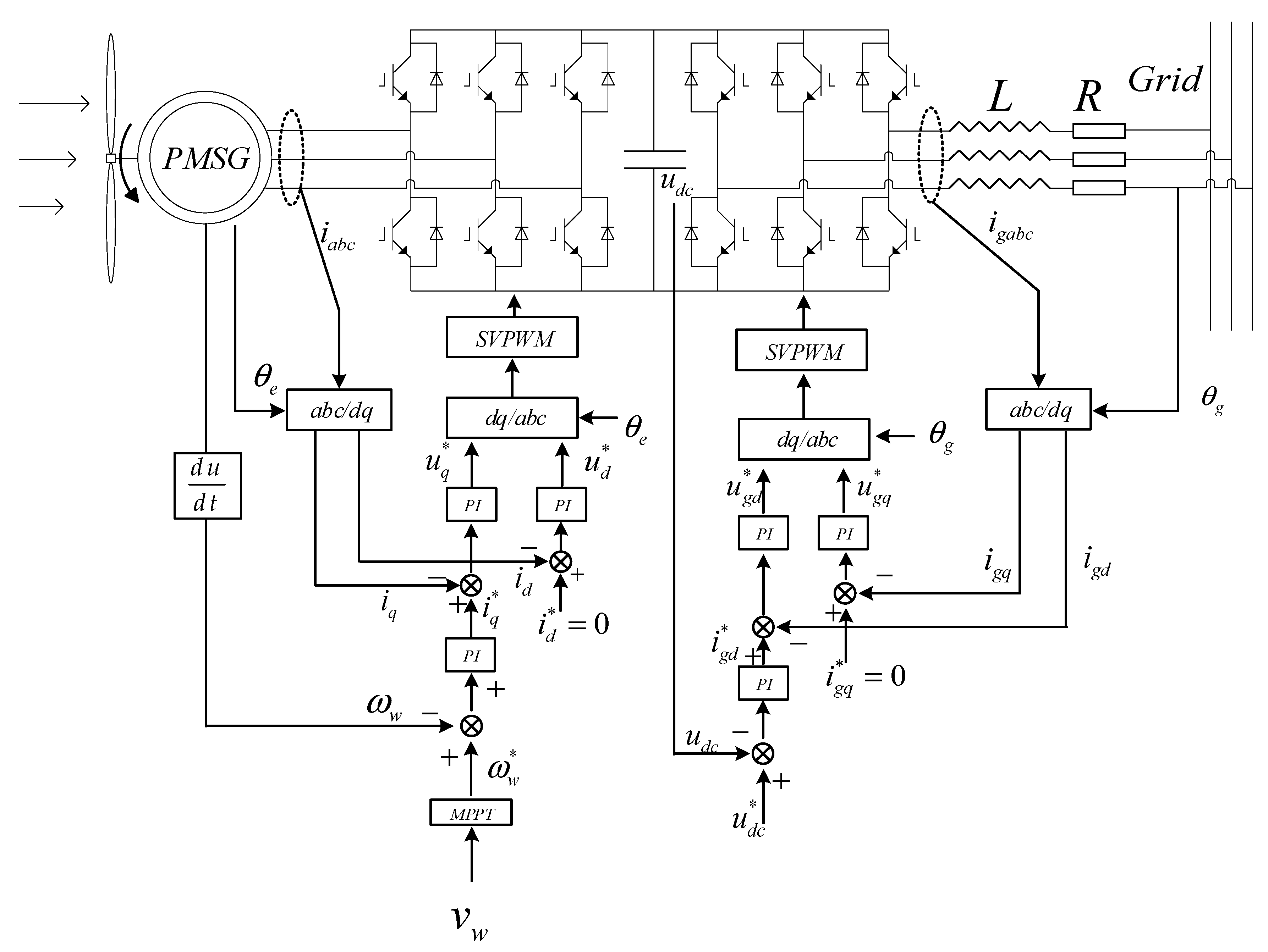
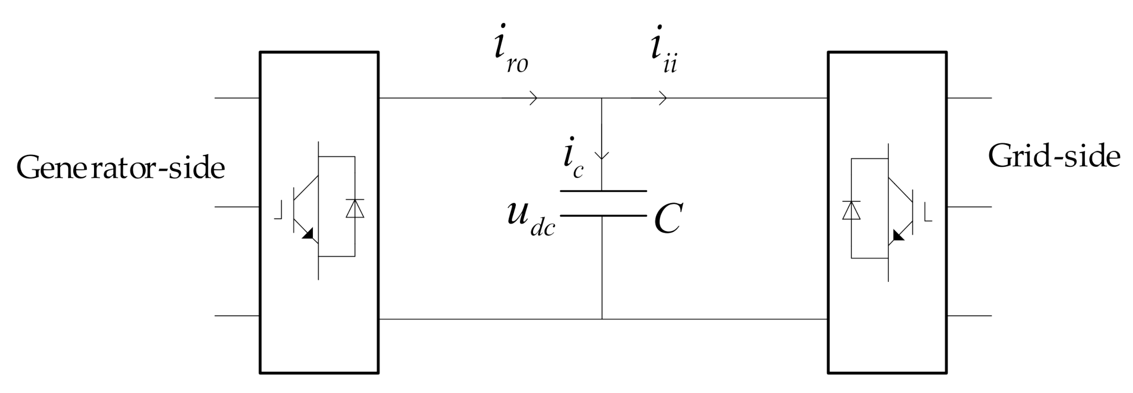
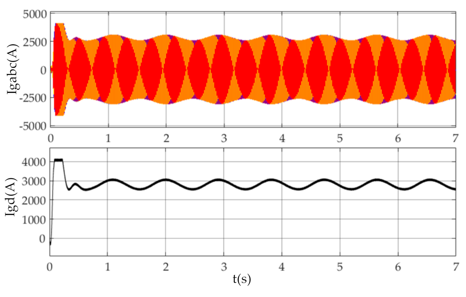
2.2. Ripple Distribution in Converts and the Grid Connection Point

In a PMSWT system, as shown in Figure 2, the ripple current can be described with power constrains of the converter because there is no power consumption in converter. The sketch diagram of converter can be drawn as the following:
In Figure 5, the current and voltage in the DC link are noted; when the ripple current flows into the converter, there will be a ripple in the current, voltage and power of DC link, which will cause power quality issues after flowing into the grid. The DC link current under wind shear can be obtained from power constraints as:
P g e n t = P d c t
In Equation (10), P g e n is the output power from the generator, and P d c is the input power of the DC link. Based on Equation (11), the DC link current i r o can be obtained from:
P g e n t = u q t i q t + u d t i d t P d c t = u d c t i r o t
Combining Equation (12) with Equations (7) and (10) and ignoring the harmonics produced by rectification, i r o can be considered as a combination of a steady component and a ripple component as Equation (13), where i ˜ r o t = A r o cos 3 ω w c t + θ δ .
i r o t = i r o c + A r o cos 3 ω w c t + θ δ
The current distribution in the converter also satisfies Equation (14) based on KCL. The original control strategy of the grid-side converter is to keep the capacitor voltage u d c steady, so the ripple of the capacitor current is negligible. Thus, the current ripple correlation is as Equation (15).
i r o t = i c t + i i i t
i ˜ r o t = i ˜ i i t
The current ripple i ˜ r o t is flowing into the grid line bringing power quality issues, which is similar to the interharmonics in the generator-side. The grid-side d-axis current i g d can be calculated based on the power constrains:
i gd   t = u d c t u g d t i i i t
So, the d-axis current can also be considered as a combination of a steady ingredient and a ripple component:
i g d t = i ¯ g d + i ˜ g d t = i g d c + A i g d cos 3 ω w c t + θ δ
By the coordinate transformation, the d-axis grid current in static three-phase coordinates is:
i g a t i g b t i g c t = i g d c sin ω g t sin ω g t 2 3 π sin ω g t + 2 3 π A i g d sin [ ( ω g + 3 ω w c ) t + θ δ ] + sin [ ( ω g 3 ω w c ) t θ δ ] sin [ ( ω g + 3 ω w c ) t 2 3 π + θ δ ] + sin [ ( ω g 3 ω w c ) t 2 3 π θ δ ] sin [ ( ω g + 3 ω w c ) t + 2 3 π + θ δ ] + sin [ ( ω g 3 ω w c ) t + 2 3 π θ δ ]
In Equation (18), the current interharmonics in the grid line distribute besides the power frequency of the grid, which is 50 ± 3ωwc/(2π) Hz.
When the current interharmonics are flowing through the grid line, there will be voltage fluctuation on the line because of line impedance, which can be described as below:
u g a ( t ) u g b ( t ) u g c ( t ) = i g d c sin ω g t sin ( ω g t 2 3 π ) sin ( ω g t + 2 3 π ) Z g a 0 0 0 Z g b 0 0 0 Z g c A i g d sin [ ( ω g + 3 ω w c ) t + θ δ ] + sin [ ( ω g 3 ω w c ) t θ δ ] sin [ ( ω g + 3 ω w c ) t 2 3 π + θ δ ] + sin [ ( ω g 3 ω w c ) t 2 3 π θ δ ] sin [ ( ω g + 3 ω w c ) t + 2 3 π + θ δ ] + sin [ ( ω g 3 ω w c ) t + 2 3 π θ δ ] Z g a 0 0 0 Z g b 0 0 0 Z g c
In Equation (19), Z g a , Z g b and Z g c are the line impedance shown in Figure 2. As shown in Equation (19), there are interharmonic components in the voltage drop of the grid line, which reveal the essence of power quality issues caused by wind shear: the current interharmonics cause the voltage interharmonics on the grid line, which, based on Equations (18) and (19), can be explained as a 50 Hz AC voltage with its amplitude changing periodically, which is also known as a flicker in [5].
According to the above, the fluctuation caused by the wind shear brings the same frequency power ripple in the converter and is transmitted to the side of the grid.

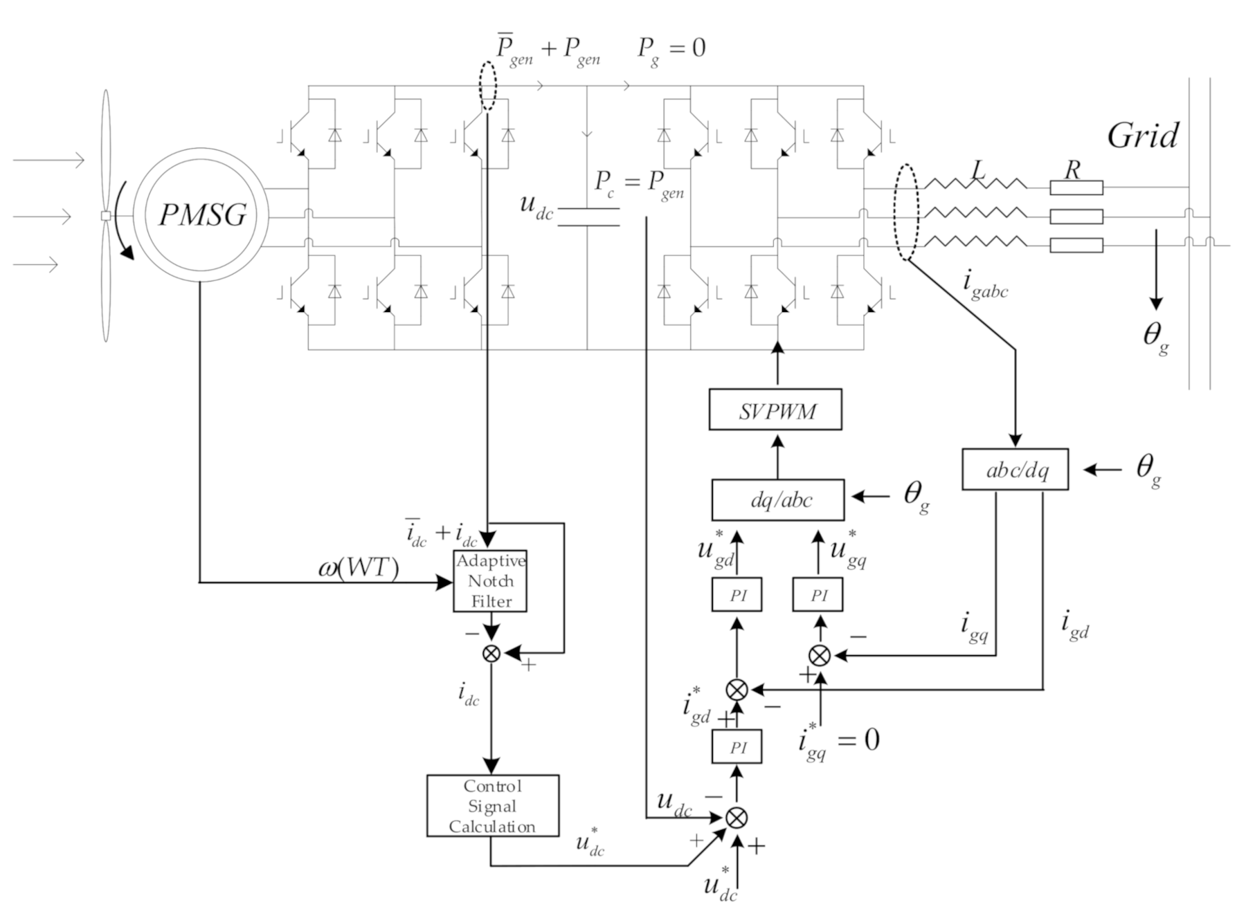
3. Fluctuation Power Suppression Method Based on Ripple Current Extraction by Adaptive Notch Filter

To achieve a perfect suppression result, the active suppression method is proposed to prevent wind shear power ripple from entering the grid, and the procedures are as follows. First, an adaptive notch is used to extract the current ripple component of generator-side convert to calculate the additional voltage control signal. Second, the additional control signal injected into the grid-side converter makes the DC-side capacitor fluctuate in a controlled condition, so that the power ripple from the generator-side convert is absorbed by the capacitor, and no ripple enters the grid-side convert and the grid connection point; that is, the ripple suppression is completed in the DC link.

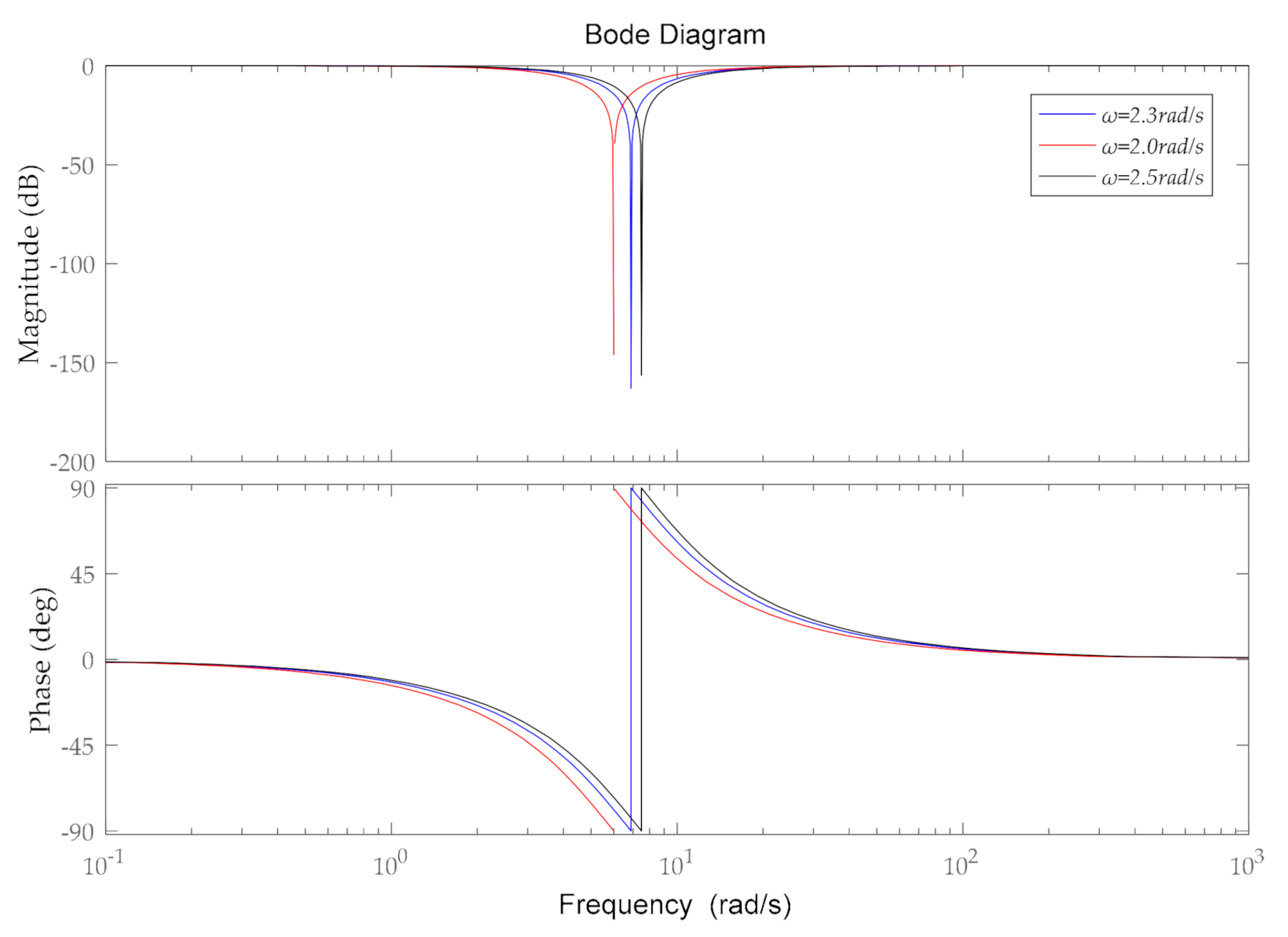
3.1. Ripple Current Extraction by Adaptive Notch Filter

Based on the characteristic of the ripple current in i r o from Equation (12), the frequency of ripple current is 3 times the basis frequency of the rotor speed; so, to extract a current signal with a clear frequency characteristic, a current extraction method based on an adaptive notch filter is proposed.
The adaptive notch filter is a notch filter with a changeable center frequency to accomplish the task of filtering out signals with different frequencies. The transfer function of an adaptive notch filter can be written as:
G s = s 2 + ω 2 W T s 2 + k ω W T s + ω 2 W T
In Equation (20), ω ( W T ) is the changeable center frequency of notch filter, which is 3 times that of the rotation frequency of wind turbine; k is the filter coefficient which is related to the bandwidth and gain of the filter. The bode diagram of the adaptive notch filter is shown as below:
As shown in Figure 6, the center frequency of the notch filter changes with rotor speed so it can filter out the current ingredient of center frequency accurately.
While the current from the generator-side to converter iro can be written as a combination in a different frequency as:
i t = i 1 t + i 2 t + + i r t + i n t
by adding the adaptive notch filter to the current signal from iro, the output signal can be expressed as:
i n o t = i 1 t + i 2 t + i n t
Equation (22) is the current signal after the notch filter; the ripple current component with a certain frequency is filtered by the notch filter. By performing subtraction, the ripple current can be obtained as:
i r t = i t i n o t
When the wind speed changes, the rotor speed will change under the control of the generator-side to fit the maximum power point, which will also cause the change in ripple frequency. In order to ensure the accuracy of ripple current extraction under variable wind speed, the center frequency of the adaptive notch filter can be obtained from the rotor speed sensor of PMSG. The ripple current component obtained by the ripple extraction method based on the adaptive notch filter will be used to generate a voltage control signal so that the capacitor can absorb the ripple power from generator-side.

3.2. Fluctuation Power Supression Method

In order to stop the current interharmonics from flowing into the grid line, the ripple power must be absorbed before it reaches the grid-side inverter. Meanwhile, it is clear in Figure 2 that there is only one capacitor in the PMSWT system which can be used as power storage equipment. Therefore, if the ripple power can be absorbed in the capacitor before it reaches the grid-side, the existence of power quality issues such as flicker and current interharmonics can be erased.
Since the flow of ripple power in the PMSWT system has been analyzed, and the frequency characteristic of ripple current, ripple voltage and ripple power is obtained, the equation of ripple power from the generator-side and the power in the capacitor branch can be expressed as:
P g e n = i ¯ r o + i ˜ r o u ¯ d c + u ˜ d c = i ¯ r o u ¯ d c + i ¯ r o u ˜ d c + u ¯ d c i ˜ r o + u ˜ d c i ˜ r o
P c = u d c i ˜ c = u ¯ d c C d u ˜ d c d t + u ˜ d c C d u ˜ d c d t
Because of the low proportion of ripple, the double frequency ripple power in Equations (24) and (25) can be ignored; thus, the description of capacitor voltage when the ripple power from the generator-side equals the power absorbed in the capacitor can be obtained as:
i ¯ r o u ˜ d c + u ¯ d c i ˜ r o = u ˜ d c C d u ˜ d c d t
Equation (26) can be rewritten in a complex frequency domain as:
u ˜ d c s = 1 s C i ¯ r o u ¯ d c i ˜ r o s
When the voltage of the capacitor fluctuates as described in Equation (27), the capacitor will absorb all the ripple power in 3p frequency, which is caused by wind shear, to eliminate the interharmonics of the grid line. According to the basic control strategy of the grid-side inverter shown in Figure 2, the ripple power absorption in the capacitor can be achieved by adding a control signal to the voltage loop of the grid-side control to make the capacitor voltage fluctuate artificially, and the voltage control signal can be obtained from Equation (27).
The ripple power suppression method combined with the ripple current extraction method can be expressed as:
In Figure 7, the current ripple extracted by an adaptive notch filter is used to generate the voltage control signal, for which center frequency is obtained from the rotor speed sensor from PMSG. The control signal calculation module generates the ripple voltage control signal as in Equation (27), so the capacitor voltage will fluctuate artificially to absorb the ripple from generator, then suppress the power fluctuation and eliminate the current interharmonics of grid line.

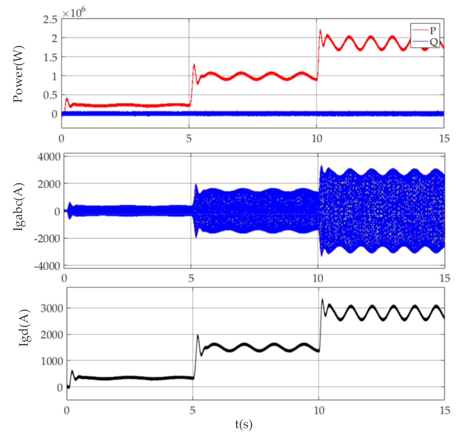
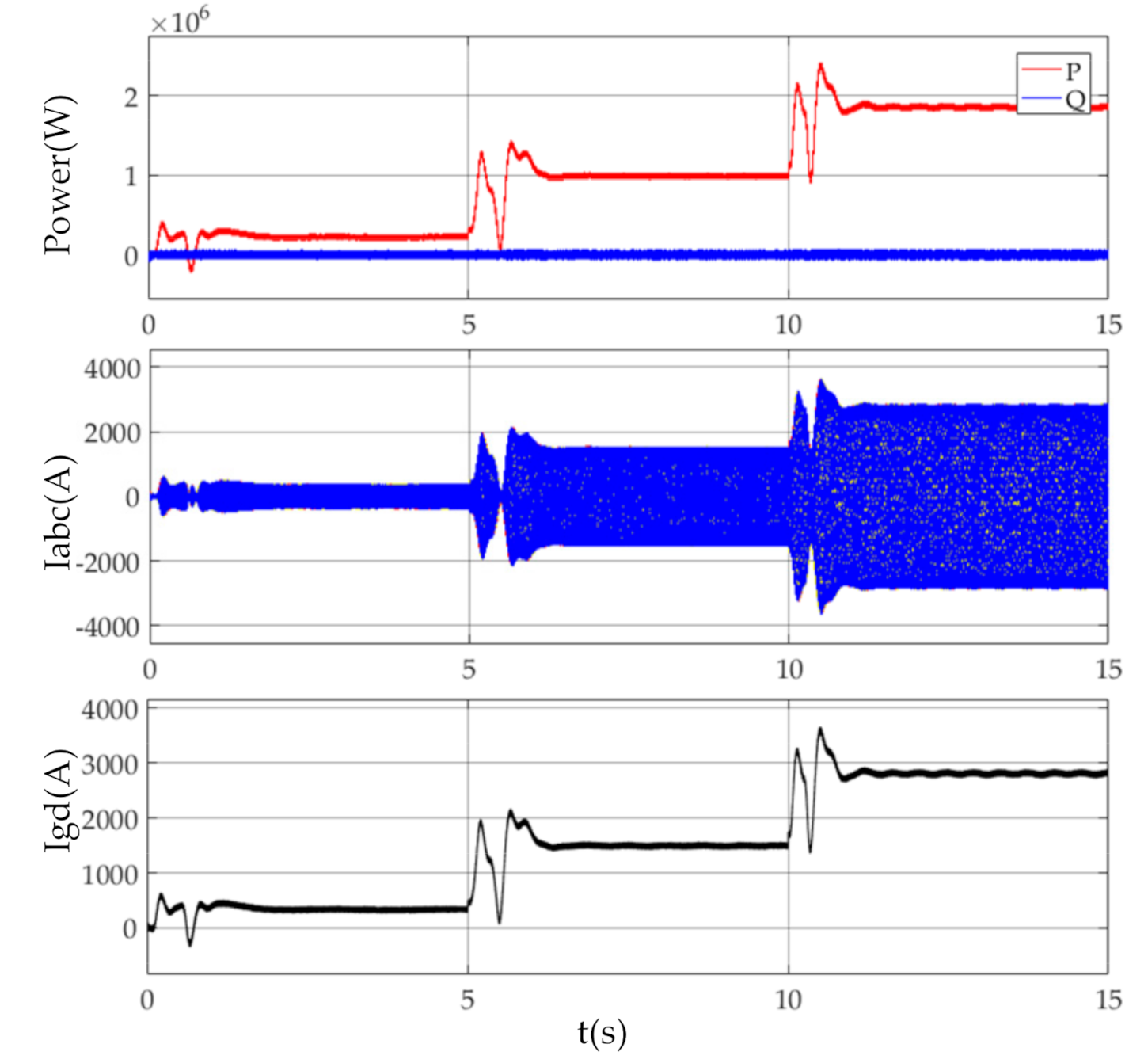
4. Simulation Results

To verify the accuracy of the ripple extraction method and the effectiveness of ripple power suppression method, a simulation of three blades PMSWT system with wind shear input was built in Matlab/Simulink. The rated power of the PMWST system is 2 MW, the rated speed is 2.5 rad/s, the number of pole pairs is 30, and the reference value of the DC link capacitor voltage is 1200 V. In order to obtain a better view of the relation between all ripples inside the PMSWT system, α was 0.2; the rotor speed under variable wind speed with step change is shown in the Figure 8:
As shown in Figure 8, the wind speed was 6 m/s from 0 s to 5 s, 10 m/s from 5 s to 10 s, and 14 m/s from 10 s to 15 s; when the wind speed step was higher, the amplitude of maximum wind speed difference on the surface of the wind wheel was larger; and the rotor speed and the amplitude of the torque ripple increased. The statistics of torque and rotor speed are listed in Table 1:
As shown in Table 1, when the ripple frequency increased because of the increase in wind speed, the frequency of ripple was 3p, and the percentage of torque ripple stayed steady.
To simplify the analysis progress and obtain a better analysis result about current and voltage ripple, the wind speed was set at 13 m/s, the rotor speed was 2.3 rad/s, and the ripple frequency was 3p which equals 1.1 Hz; the waveform of the stator current of PMSG was obtained as:
As in Figure 9, the amplitude of the three-phase stator current changed periodically, and from FFT spectrum analysis, there was an 8.23% ripple component at 1.1 Hz in the q-axis current.
The ripple component inside the converter after flowing into the DC link of converter is shown in Table 2:
In Table 2, the ripple component and steady component of the generator-side and grid-side both fit the power Equation (12) as:
i ¯ r o i ¯ q = i ˜ r o i ˜ q
i ¯ i i i ¯ g d = i ˜ i i i ˜ g d
The phase of the capacitor voltage is 12°, which is opposite to the voltage phase caused by i r o meaning instead of absorbing part of the ripple current from generator-side, the ripple current of the capacitor branch is actually flowing into grid together with the ripple current in i r o .
The effect of the capacitor branch can be described using Equation (27). By bringing in the statistics of u d c in Table 2, Equation (21) can be calculated as:
i ˜ g d 1 t = 49.01 cos 6.9 t + 12 °
Meanwhile, the ripple current from the generator-side can be written as in Table 2:
i ˜ r o t = 144 cos 6.9 t 66 °
When there is no capacitor branch and the ripple current from the generator-side totally flows into the grid-side, the ripple power of the d-axis current of the grid-side can be calculated as:
i ˜ g d 2 t = 229.86 cos 6.9 t 66 °
The sum of Equations (30) and (32) is:
i ˜ g d ( t ) = 245 cos 6.9 t 55 °
The d-axis ripple current of the grid-side in Equation (33) fits the statistic in Table 3, which means that the ripple current of capacitor branch is added to the ripple current from the generator-side, causing the d-axis ripple current of the grid side.
The waveform of current in the grid-side is shown in the Figure 10:
The component percentage at 1.1 Hz of grid line current was 8.82%:
In order to verify the effectiveness of the control method proposed in this paper, a set of comparative simulations was made. When the wind speed step changes as in Figure 8, the waveform of current and power in the grid line are shown as:
As shown in Figure 11, when wind speed increased, the ripple frequency changed together with the rotor speed in Table 1, and there were ripples in both the power and grid line current, the details of which are shown in the Table below:
As shown is Table 3, there is ripple power in the grid-line, which is the cause of current interharmonics in Figure 11. To erase the existence of ripple in the grid line, the proposed ripple power absorb method was applied. When ripple frequency changed with wind speed, the adaptive notch filter extracted the ripple current signal from i r o to generate the voltage control signal which was added to the grid-side control loop. The waveform of the grid line power and current is shown as the figure below:
As shown in Figure 12, the ripple power and current interharmonics have been erased from the grid line which means the ripple absorb method proposed in this paper has worked.
The statistics of ripple in grid connection point are shown in Table 4:
According to the ripple variation between Table 3 and Table 4, after being suppressed, the ripple reduction percentage is as Table 5.
Based on Figure 12 and Table 5, the ripple was decreased mostly by the proposed suppression method, and the power ripple reduction percentage was up to 85% under MPPT, which was verified by the simulation at 3 different wind speeds.

5. Conclusions

In this paper, a PMSWT system was selected as the wind shear research object; the ripple’s transfer mechanism analysis and suppression method verification were completed. The fluctuations or ripples were caused by wind shear transfer from the generator-side, via PWM converts, to the grid; moreover, their frequency is triple rotor speed. According to the frequency characteristic of ripple, an adaptive notch filter was used to extract the current ripple in the generator-side convertor to calculate the additional voltage control signal. Then, the active suppression method was proposed to make the convert DC link’s original capacitor fluctuate initiatively to absorb the ripple power from the generator, so no ripple entered the grid-side convert and the grid connection point, which ensured the power quality flowing to the grid under wind shear. The simulation shows that the DC-link ripple suppression method combined with the notch filter is highly effective, and the ripple reduction percentage is up to 85%.The proposed suppression method will be modified further to improve the suppression effect at low wind speed.

Author Contributions

Conceptualization, Z.L.; methodology, G.H.; software, G.H.; validation, X.W.; formal analysis, Y.C.; investigation, W.X.; resources, Y.C.; data curation, Y.C.; writing—original draft preparation, X.W. and G.H.; writing—review and editing, Z.L. and H.W.; visualization, G.H.; supervision, Z.L.; project administration, H.W.; funding acquisition, H.W. All authors have read and agreed to the published version of the manuscript.

Funding

This research received no external funding.

Conflicts of Interest

The authors declare no conflict of interest.

References

  1. Bo, L.; Zhi-Jia, H.E.; Hao, J. Wind power status and development trends. J. Northeast Dianli Univ. 2016, 36, 7–13. [Google Scholar]
  2. Mohammadi, E.; Fadaeinedjad, R.; Naji, H.R. Investigation of horizontal and vertical wind shear effects using a wind turbine emulator. IEEE Trans. Sustain. Energy 2018, 10, 1206–1216. [Google Scholar] [CrossRef]
  3. Guo, P. Influence Analysis of Wind Shear and Tower Shadow on Load and Power Based on Blade Element Theory. In Proceedings of the IEEE 2011 Chinese Control and Decision Conference, Mianyang, China, 23–25 May 2011; pp. 2809–2812. [Google Scholar]
  4. Dou, Z.L.; Wang, H.; Ling, Z.B. Research on wind turbine emulator system based on blade element theory. Adv. Technol. Electr. Eng. Energy 2011, 30, 1–5. [Google Scholar]
  5. Dale, S.L.; Dolan, P.; Lehn, W. Simulation model of wind turbine 3p torque oscillations due to wind shear and tower shadow. IEEE Trans. Energy Convers. 2006, 21, 718–724. [Google Scholar]
  6. Jeroen, D.M.D.K.; Tine, L.V. Shaft speed ripples in wind turbines caused by tower shadow and win shear. IET Renew. Power Gener. 2013, 8, 195–202. [Google Scholar]
  7. Chavan, D.S.; Bhide, S.D.; Karandikar, P.B. Effect of Vertical Wind Shear on Flicker in Wind Farm. In Proceedings of the IEEE Global Humanitarian Technology Conference: South Asia Satellite, Trivandrum, India, 23–24 August 2013. [Google Scholar]
  8. Hu, W.; Su, C.; Chen, Z. Impact of Wind Shear and Tower Shadow Effects on Power System with Large Scale Wind Power Penetration. In Proceedings of the 37th Annual Conference of the IEEE Industrial Electronics Society, Melbourne, Australia, 7–11 November 2011; pp. 878–883. [Google Scholar]
  9. Bahramjerdi, R.F.; Moschopoulos, G.; Moallem, M. The impact of tower shadow, yaw error, and wind shears on power quality in a wind-diesel system. IEEE Power Energy Soc. Gen. Meet. 2009, 24, 102–111. [Google Scholar]
  10. Roohollah, F.; Gerry, M. The impact of tower shadow, yaw error, and wind shears on power quality in a wind–diesel system. IEEE Trans. Energy Convers. 2009, 24, 102–111. [Google Scholar]
  11. Koldo, R.; Guttierez, J.J.; Lehn, G. Experimental study of the summation of flicker caused by wind turbines. Energies 2019, 12, 2404. [Google Scholar]
  12. SeokJu, K.; Jaewoo, K. Reactive power management based on voltage sensitivity analysis of distribution system with high penetration of renewable energies. Energies 2019, 12, 1943. [Google Scholar]
  13. Hu, Y.P. Research status and development trend on large scale wind turbine blades. J. Mech. Eng. 2013, 49, 140–151. [Google Scholar] [CrossRef]
  14. Weihao, H.; Yunqian, Z. Flicker mitigation by speed control of permanent magnet synchronous generator variable-speed wind turbines. Energies 2013, 6, 3807–3821. [Google Scholar]
  15. Shen, W.; Zheng, X. An Active Damping Scheme of the Voltage-Source Converter Driving the Induction Machine Damping Unit for Mitigating Subsynchronous Oscillation in Power Systems. In Proceedings of the 11th IET International Conference on AC and DC Power Transmission, Birmingham, UK, 10–12 February 2015. [Google Scholar]
  16. Gamini Jayasinghe, S.D.; Mahinda, V. A dual inverter-based supercapacitor direct integration scheme for wind energy conversion systems. IEEE Trans. Ind. Appl. 2013, 49, 1023–1030. [Google Scholar] [CrossRef]
  17. Diaz-Gonzalez, F.; Bianchi, F.D. Control of a flywheel energy storage system for power smoothing in wind power plants. IEEE Trans. Energy Convers. 2014, 29, 204–215. [Google Scholar] [CrossRef]
  18. Weihao, H.; Zhe, C. Flicker mitigation by active power control of variable-speed wind turbines with full-scale back-to-back power converters. IEEE Trans. Energy Convers. 2009, 24, 640–650. [Google Scholar] [CrossRef]
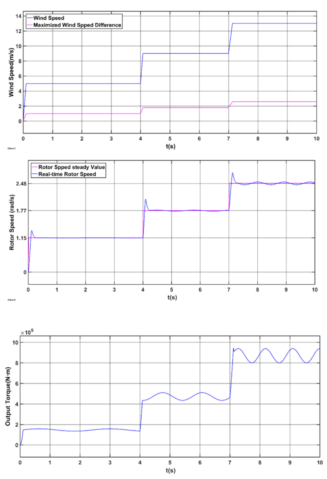
Figure 1. Schematic of some wind turbine parameters.
Energies 13 05088 g001
Figure 2. The topology of the permanent magnet synchronous wind turbine (PMSWT) system and dual-loop control strategy.
Energies 13 05088 g002
Figure 3. Diagram of generator-side in q-axis.
Energies 13 05088 g003
Figure 4. Equivalent circuit of PMSG in d/q-axis. (a) d-axis circuit; (b) q-axis circuit.
Energies 13 05088 g004
Figure 5. Sketch diagram of the converter in PMSWT system.
Energies 13 05088 g005
Figure 6. Bode diagram of notch filter.
Energies 13 05088 g006
Figure 7. Ripple power suppression method based on current extracting by adaptive notch filter.
Energies 13 05088 g007
Figure 8. Ripple status of PMSG under wind shear.
Energies 13 05088 g008
Figure 9. The waveform of stator current.
Energies 13 05088 g009
Figure 10. The waveform of grid line current.
Energies 13 05088 g010
Figure 11. Waveform of grid connection point power and current.
Energies 13 05088 g011
Figure 12. The waveform of grid connection point power and current after suppression.
Energies 13 05088 g012
Table 1. Statistics of rotor speed and torque under wind shear.
Time (s)Rotor Speed Steady Value (rad/s)Torque Ripple Frequency (Hz)Torque Ripple Percentage (%)
0–51.15 (0.18 Hz)0.558.01
5–101.77 (0.28 Hz)0.857.98
10–152.48 (0.39 Hz)1.187.99
Table 2. Ripple composition of grid connection point under variable wind speed.
Time (s)Rotor Speed Steady Value (rad/s)Ripple Frequency (Hz)Ripple Active Power Percentage (%)D-axis Ripple Current Percentage (%)
0–51.060.558.317.75
5–101.770.858.458.89
10–152.481.187.807.92
Table 3. Ripple component of DC-link.
Current Componentiq(A)ir0(A)udc(V)ic(A)iii(A)igd(A)
Steady Component2576165212000.0916522801
Ripple Amplitude212.1144.01.6911.47155.3247.9
Frequency (Hz)1.11.11.11.11.11.1
Phase (°)−73.4−66.012102−66.9−66.5
Table 4. Ripple component of grid connection point ripple after suppression.
Time (s)Ripple Active Power Percentage (%)D-axis Ripple Current Percentage (%)
0–51.141.14
5–100.190.17
10–150.150.13
Table 5. Ripple reduction percentage of grid connection point after suppression.
Time (s)Wind Speed
V0 (m/s)
Ripple Active Power Reduction (%)D-axis Ripple Current Reduction (%)
0–5586.3%85.3%
5–10997.8%98.1%
10–151398.1%98.4%

