Abstract
The characteristics of spark ignition with a constant volume combustion chamber (CVCC) is evaluated for the efficiency of capacitive-assisted ignition (CAI), such as spark kernel and flame growth. The conventional spark method and matching effect of high voltage (MEHV) method are evaluated to compare the spark growth distribution characteristics. To do this study, a plasma system is used and is consisted of input power, three capacitors, a transformer, high voltage cable, J-type of a spark plug, diode, and CVCC. The experiment is conducted under various operating conditions, such as 1 bar, 295 K of initial temperature, 50, 100, 150 V of ignition box, 400 V of MEHV, 0.7 ms of spark duration, and 0 kΩ of plug resistor. The results show that the spark growth at the initial voltages of 100 V and 150 V has the same characteristic, and the surface area is increased by 13 mm2 at 150 V compared to 100 V because capacitance energy stored in three capacitors is efficiently induced by the effect of dielectric breakdown and electron collision. Consequently, the spark growth of MEVH is widely distributed atmospheric more than the conventional spark, and the internal temperature of the spark kernel could be presumed to change the non-thermal plasma to thermal plasma by MEHV.
1. Introduction
The spark ignition used in internal combustion engines is one of the promising technologies which can improve the combustion performance. In the spark-ignition engine, the combustion reaction leads to physical properties by an ignition source under the ending of the compression in a cylinder cycle. Nowadays, the spark ignition system applies to the combustion technique based on the higher energy to induce higher efficiency. In order to induce higher energy, the ignition coil is still studying the energizing winding to magnify the efficiency of a magnetic field. The plasma has a wide range of ignition methods, i.e., spark ignition discharge (SID) [1], corona ignition discharge (CID) [2], microwave-assisted discharge (MAD) [3], nano-second discharge (NSD) [4], radiofrequency discharge (RFD) [5], and so on. These sources can be defined as the electron temperature (Tg) and electron number (E/N) by the Saha ionization equation. Table 1 shows the plasma discharge properties [6].

Table 1.
Plasma discharge properties.
In more detail, the velocity distribution of a particle in equilibrium can be described by Maxwell–Boltzmann distribution (MBD) of one-dimension, and MBD is defined as the following equation [7]:
where constant value (A) is related to density (n), and n is defined as the following integral value [8]:
In plasma properties, the most important thing is to control the capacitor energy stored in a capacitor. This capacitor is used in all of the plasma types because the voltage is properly stored. In particular, the capacitive discharge ignition (CDI) is capable of designing the circuit system simply. The matching effect of high voltage (MEHV) is obtained using two different energies by the electric clash between plug electrodes [9].
The matching effect of high voltage (MEHV) is well-known for a technical method capable of inducing the plasma discharge and expanding the kernel volume [10]. The matching effect of high voltage (MEHV) can be easily seen between the cathode and anode combined with two different circuits of the ignition system, and the discharge of MEHV is expanded between spark plug gaps by electron collision, which is transferred from the cathode to anode. Namely, the electron collision has the effect of momentary short in the electric circuit and includes the effect of electrical breakdown. This physical explanation of MEHV is written in detail as the following reference.
The spark-ignition engine is required to apply the effective energy for improving fuel efficiency. Because the spark ignition system using low-temperature plasma has a limitation in all of the high-speed engine types, the conventional ignition technique using the capacitive discharge ignition is essentially required to apply the MEHV for the spark-ignition engines.
The spark ignition bridged by two different energies becomes induced in a higher effect than the single energy, and these methods can be found in the results investigated in the previous researches.
We have carried out the research on the reaction progress of thermodynamic combustion based on the arc and jet plasma energies using MEHV [11]. While conducting the experiment, it could be demonstrated that combustion efficiency is improved by the effect of high voltage. Besides, from the results of testing the kernel, IMEP (Indicated mean effective pressure), and response based on three plasma energies, it could be noticed that the combustion reaction is quickly promoted by higher energy [12]. Besides, we have physically proved that MEHV has positive effects on progressive combustion, including the lean burn characteristics [13], flame thickness and velocity, and combustion flame propagation [14].
Therefore, our research is continuously investigating to obtain the advantage of MEHV effects. The main goal of this research paper is to study the fundamental properties of the effect of capacitive-assisted ignition on spark kernel and flame growth in a constant volume combustion chamber [15]. This work is mainly focused on the effect of the spark ignition, voltage, current, propagation, energy, and growth in atmospheric air.
The structure of this paper is described in subsequent sections. Section 2 represents the research method, including the plug design and composition, MEHV circuit system, and experiment devices and conditions. Section 3 discusses the experimental results comparing the two different spark ignitions and offers the technical data of voltage and current, energy, and propagation and growth of spark ignition. The main summary and conclusion are given in Section 4, followed by the references.
2. Research Method
2.1. Spark Plug Design and Composition
Figure 1 shows the composition of a conventional spark plug, which applies to the ignition system for gasoline engines. This spark plug is used to investigate internal structures and material characteristics as a fundamental study. A spark plug is composed of various materials, such as terminal nut, insulator, hexagon socket, metal shell, gasket, corrugations, powder, and copper core. In general, the spark plugs have a constant resistance of about 5 kΩ between central electrodes. In order to intentionally increase the ignition energy, the plug model designed in this research is modified to have 0 kΩ resistance. The electrode material is employed with the iridium and platinum to well induce electric energy. More specifically, a center electrode uses an iridium material, and the ground electrode is combined with a platinum material on the nickel surface.
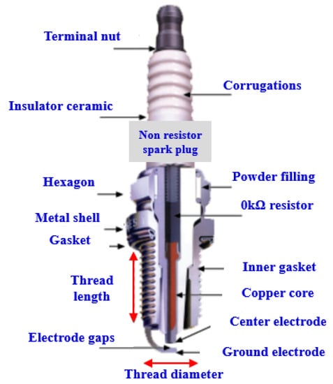
Figure 1.
Composition of the non-resistor spark plug.
With regards to the electrode gap of a spark plug, the electric voltage could be increased by increasing the length between anode and cathode (positive and negative electrodes).
However, the widening of the electrode gap could damage the ignition system, which includes a transformer, cable, capacitor, resistor, and spark plug. Once the pressure is increased inside a constant volume chamber, it could be occurred to miss the fire spark since electric energy is not easily induced between electrodes. On the other hand, a magnetic field is significantly affected by the length of the electrode gap. If the gap is designed shorter than the standard, the electric voltage would be diminished because the electric power is also reduced. Even the effect of the combustion reaction could be decreased due to propagating a downsized kernel particle between electrodes.
In a constant volume combustion chamber of gasoline engines, as seen in Figure 2, the J-type electrode of a spark plug is important to fit the accurate direction since the location of the ground electrode may be disturbed when mixing an air-fuel.
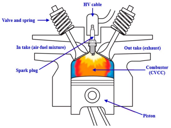
Figure 2.
Spark plug location in a constant volume combustion chamber.
2.2. Conventional and MEHV Circuit System
Figure 3 represents a schematic diagram of conventional and MEHV circuit systems used in a spark ignition system. In the conventional spark system, the electric voltage and current are induced in the order of battery, primary coil, secondary coil, high voltage cable, and spark plug. During the flow of the electric voltage and current in a cable, the spark energy is discharged by a ground electrode integrated with all of the negative circuits. The conventional ignition system becomes reliant on the electromotive force (EMF) of a transformer by the switching effect of a transistor. In a transformer (ignition coil), the primary and secondary coils are being isolated from two plates to prevent the inverse voltage and current during creating a spark.
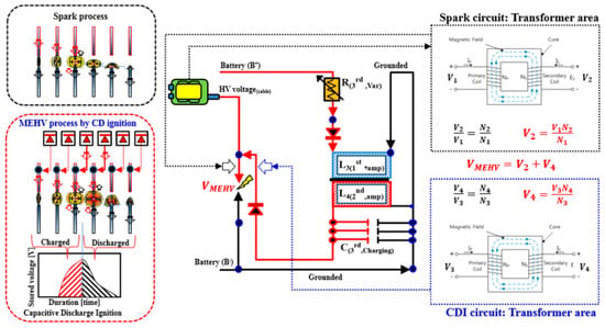
Figure 3.
A schematic diagram of the conventional and matching effect of high voltage (MEHV) circuit systems using spark ignition (SI) engines.
In the MEHV plasma system, the input power is used to connect a 12-VDC battery voltage. In order to store three capacitor energies, another transformer is integrated with the conventional ignition circuit. The voltage and current of MEHV are generated by an added transformer, which has 50 turns of the primary coil and 80 turns of the secondary coil. The maximum energy of MEHV is stored up to 150 mJ inside three capacitors.
A diode located in HV(High voltage) cable is used to prevent the damage by inverse voltage when discharging a spark between electrodes. This MEHV is based on capacitive discharge ignition because this work depends on intensive capacitor energy. Therefore, the basic equation is written as [16],
where C is the capacitance, ε the permittivity of dielectric, S the surface area of the electrode, and d the thickness of the dielectric. Figure 4 shows a schematic of a dielectric capacitor. In order to easily understand, Table 2 represents the advantages and disadvantages of electrical energy stored in the capacitor, and Table 3 shows the MEHV circuit specifications.
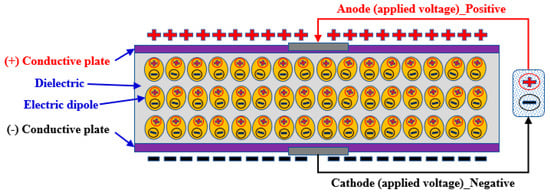
Figure 4.
A schematic of a dielectric capacitor.

Table 2.
Advantages and disadvantages of electrical energy and capacitor designed in MEHV.

Table 3.
MEHV circuit specifications.
2.3. Experimental Devices and Methods
Figure 5 depicts a schematic diagram of the experimental device and CVCC (Constant volume combustion chamber) system to test the physical properties of the conventional spark and MEHV plasma spark, i.e., voltage, current, spark energy, spark kernel propagation, and spark kernel growth in atmospheric air. In order to replicate the atmospheric air, the gas fuels are accurately diluted inside a CVCC using 21% O2, 78% N2, and 1% Argon. In order to prevent the expansion of internal gases, the gas pressure is regulated by mass flow controllers from 100 bar to 1 bar (at 295 K) [17]. The supply system is adjusted to calibrate pressure errors. The chamber temperature is controlled by a proportional-integral-derivative (PID) controller. Inside a CVCC, the pressure sensor is applied to the monitoring method to observe the variable flow of pressure. For all of the voltage and current signals, it is utilized to record the data measured by sensors and actuators in an integral box and cDAQ LabVIEW system.
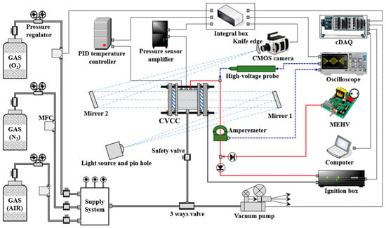
Figure 5.
A schematic diagram of experimental devices and constant volume chamber systems.
A high voltage probe is employed to collect the plasma signal induced by a transformer. Besides, an ampere meter is used to collect the data of the current signal at the same time, along with a high voltage signal.
In order to adjust the voltage strength, a variable resistor of the ignition box is added. The circuit of the initial pulse is integrated with cDAQ, high voltage probe, and oscilloscope. A high-speed camera is bridged with a base terminal of IGBT (Insulated gate bipolar transistor) transistor to record the starting signal of snapshots as 20,000 fps. A CVCC is combined with a surface plate to fix its body. To enhance the voltage strength of MEHV, it is designed to control the voltage height at the input transformer from 300 V to 600 V. In an ignition box, the conventional circuit system is developed to increase the transformer voltage from 5 V to 160 V. Table 4 shows the MEHV circuit specifications.

Table 4.
Specifications of experimental devices and CVCC system.
2.4. Experimental Condition
The experiments are composed of a wide range of conditions, i.e., 1 bar in atmospheric air, 295 K of initial temperature, 50, 100, 150 V of ignition box, 400 V of MEHV, 0.7 ms of spark duration, and 0 kΩ of plug resistor [18]. The conventional spark and MEHV are applied to a CVCC system, and J-type of a spark plug is used to investigate two different kernel characteristics. Table 5 shows the experimental conditions required in this research work.

Table 5.
Experimental conditions.
3. Results and Discussions
3.1. Voltage and Current of Conventional Spark System
This section investigates the voltage and current signals to study the effect of conventional plasma in a spark plug. The x-axis of the graph is the duration time (ms), and the y-axis indicates the breakdown voltage (V), which includes the secondary voltage and current measured in an HV cable. The experiment is set by 1 mm of plug gap, 0.7 ms of pulse duration, and 50–150 V of initial voltage.
As shown in Figure 6a, the breakdown voltage is increased up to 540 V due to the switching effect of an IGBT transistor. In fact, the secondary ignition voltage is raised up to 1.5 kV, but this result has shown that the voltage height is reduced because the signal data is filtered by the FFT (Field effect transistor) method. The breakdown voltage of 50 V can be seen to increase the signal at 0 ms since a transistor is affected by surge voltage. In spark discharge duration, the measured time is 0.75 ms, and the initial duration is delayed by about 0.05 ms compared with the 0.7 ms standard. Therefore, the secondary signal can be seen to occur at an inverse voltage of 2.75 ms. In the current signal, the maximum value is increased up to 0.15 A, including abnormal noises, and the maximum timing is shown at 0.22 ms.
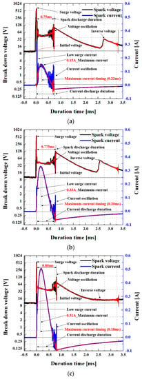
Figure 6.
Voltage and current of the conventional spark system: (a) 50 V initial voltage of the conventional spark; (b) 100 V initial voltage of the conventional spark; (c) 150 V initial voltage of the conventional spark.
As shown in Figure 6b, in 100 V MEHV, the signal trend of breakdown voltage has a similar level in comparison with 50 V initial results. However, the discharge duration of 50 V is measured at 0.775 ms, delayed by about 0.025 ms compared with 50 V. The reason for the delayed effect is that as initial voltage increases, the spark energy is also increased in proportion, and the residual electron has remained around plug electrodes.
Moreover, one can see that the current signal of 100 V is increased in double compared with 50 V. In 100 V, the noise characteristic is diminished in the entire signals because of the improvement in the current effect.
As seen in Figure 6c, the voltage trend of 150 V is increased with a very stable signal compared with the other ones. In particular, the discharge duration of 150 V is delayed up to 0.8 ms. Besides, the time difference between 100 V and 150 V occurs by 0.025 ms. The current of 150 V is remarkably increased up to 0.51 A. In the maximum current of 150 V, the delayed time is 0.18 ms. This delayed characteristic notices that as initial voltage increases, the duration time of MEHV discharge is delayed in a proportional.
Consequently, the experiment is verified that as the initial voltage increases, the current is significantly influenced by the effect of self-induction. Besides, it is demonstrated that the effect of the voltage and current signals can enhance the kernel strength between plug electrodes for the conventional spark.
3.2. Voltage and Current of MEHV System
Figure 7 shows the signal characteristics of the voltage and current measured in the MEHV system. The experiment is performed in equal conditions, as mentioned in Section 3.1. The circuit system of MEVH is bridged to the output HV cable in the conventional circuit to give a plug the capacitance energy. In this graph, because the ampere values measured by MEHV are higher than the conventional spark, the current scale is set to 2 A to easily analyze the data.
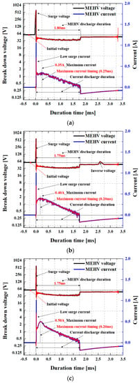
Figure 7.
Voltage and current of MEHV based on capacitive discharge ignition (CDI): (a) 50 V + 400 V initial voltage of MEHV; (b) 100 V + 400 V initial voltage of MEHV; (c) 150 V + 400 V initial voltage of MEHV.
As seen in Figure 7a, the height of breakdown voltage is increased by the matching effect of high voltage. The height of the initial voltage is started at 56 V because the capacitors are bridged with the conventional circuit.
Notably, the discharge duration of MEHV is delayed up to 1.80 mm, and the height of the discharge voltage is maintained as 40 V. The important thing in this signal is that the noise voltage does not occur, and the voltage and current signals have clear values. In the current, the maximum value of 50 V has 0.35 A at 0.25 ms. Because MEHV is integrated with the conventional circuit, the ampere is highly increased by combined energy when creating a spark. Moreover, a highly increased current seems to affect the discharge duration.
As shown in Figure 7b, the current height of MEHV is raised up to 0.40 A, and the discharge duration of the current has the maximum peak value at 0.2 ms. In comparison to the conventional current, the reason for the increased current of MEHV is that the three capacitors have large energy. As initial voltage increases the conventional spark, the current of MEHV is contributed to the energy increment while creating a spark. Therefore, it can be assumed to have a relation of energy conversion from the voltage to the current.
As shown in Figure 7c, the current of MEHV is increased up to 0.5 A more than the conventional current, and the current height has the topmost value compared with the others. This increased effect of MEHV is noticed when the current strength is enhanced by electron collision when converging two different energies.
Consequently, the current effect of MEHV is demonstrated to improve the kernel reaction by matching capacitance energy stored in three capacitors. On the downside, as the initial voltage increases, the voltage and current of MEHV are significantly delayed in comparison with the conventional spark.
3.3. Energy Comparison of Two Different Plasma Sparks
Figure 8 represents the result of the energy comparison regarding two different plasma discharges. This energy result is followed in Section 3.3. The x-axis is the duration time (ms) of the spark, and the y-axis indicates the integral energy (mJ) of spark discharge. In this graph, the integral energy is defined as the following equation:
where V is the spark voltage, I is the current or ampere, and W is the work. Therefore, VI = W (work) = J/s. The spark energy is calculated up to the maximum voltage and current values since the duration time is directly related to spark energy.
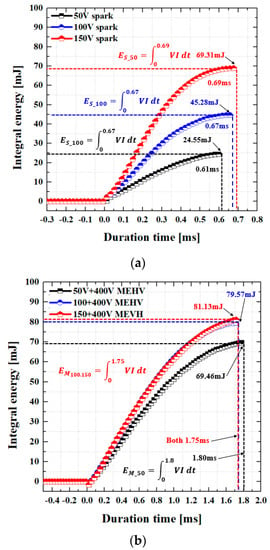
Figure 8.
Energy comparison of two different sparks: (a) The conventional spark energy; (b) MEHV spark energy.
In the conventional spark, as shown in Figure 8a, energy is increased by stage as initial voltage increases. The maximum energy of 50 V has 24.55 mJ at 0.61 ms. In the case of 150 V, the maximum energy is indicated up to 45.28 mJ at 0.67 ms. Besides, it is shown that as the initial voltage increases to 150 V, the topmost value of energy is 69.31 mJ at 0.69 ms.
On the other hand, as shown in Figure 8b, the maximum energy of 50 V MEHV is remarkably increased up to 69.46 mJ at 1.8 ms. As the initial voltages of 100 V and 150 V increase, the energy and time are shown to be almost equal. The maximum energy of 150 V MEHV is 81.13 mJ, and the topmost energy is obtained at 1.75 ms.
Consequently, the spark energy of MEHV has higher values in duration than the conventional spark. On the one hand, the stored energy of MEHV can enhance the discharging effect of spark by increasing the current strength. However, MEHV leads to the delaying effect of spark duration by an internal resistor with three capacitors.
3.4. Effect of Plasma Spark Propagation between Electrodes
Figure 9 shows the comparison result of conventional spark and MEHV sparks, which is physically propagated between plug electrodes in the atmospheric air.
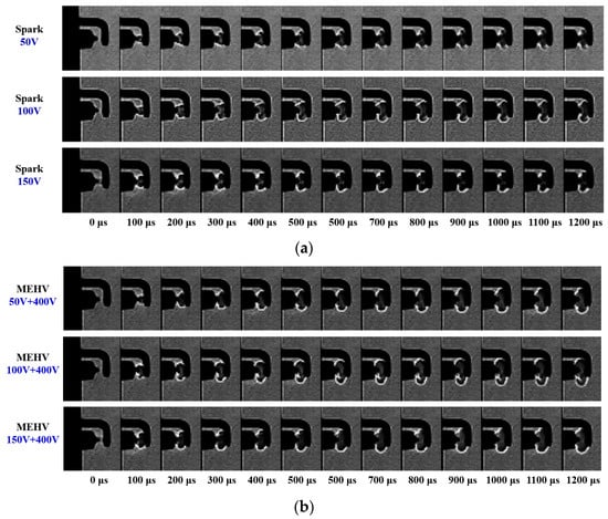
Figure 9.
Comparison result of conventional spark and MEHV sparks, which is physically propagated between plug electrodes in the atmospheric air: (a) Effect of conventional spark propagation; (b) Effect of MEHV spark propagation.
The propagation time is presented from 0 μs to 1200 μs using an image program integrated with a high-speed camera. The snapshot images are applied to the analysis method using the sharpen filter to easily visualize the spark formation. In more detail, the filtered adjustments are set by 9.96% of brightness, 1.0 of gain, 0.6 of gamma, 1.5 of sensitivity, and 0% of flare. The gap of a spark plug is fixed by 1 mm, and the spark plug is used with a non-resistance to generate the lower energy to higher energy.
As seen in Figure 9a, the spark is gradually propagated with ellipse formations. For all of the models, the initial spark starts to increase the kernel formation at 100 μs. The spark kernel of 50, 100, and 150 V initial voltages seems to rapidly grow an internal flame from 0 μs to 400 μs. As the initial voltage increases, the ionized reaction of the spark kernel is shown to accelerate the internal flame area. For example, the visualization area of the spark kernel has a relation of 150 V > 100 V > 50 V.
As shown in Figure 9b, it can be also seen that the spark kernel is higher in 150 V initial voltage than the other ones because the voltage increment has a direct relation with the current increment. The important thing is to highly and rapidly start the flame kernel growth in MEHV more than the conventional spark.
Consequently, the spark propagation of MEHV is higher in all of the internal flame areas than the conventional spark. Furthermore, it can be noticed that spark reaction ionized by MEHV in the atmospheric air is efficiently induced by internal energy converted from three capacitors more than the conventional spark.
3.5. Flame Growth Characteristics of Two Different Plasmas
This section investigates the spark growth characteristics to compare two different plasma energies. As seen in Figure 10, the x-axis is the duration time (μs), and the y-axis indicates the surface area (mm2). The data of these results is extracted from Section 3.3, and it is utilized to specifically analyze the spark growth.
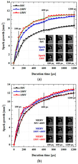
Figure 10.
Result of spark growth compared with two different plasma energies (conventional spark and MEHV): (a) Conventional spark growth; (b) MEHV spark growth.
As a result, the surface area of spark growth is definitely differentiated between the conventional spark and MEHV spark. The conventional spark of 50 V, as shown in Figure 10a, is raised up to 8.3 mm2 at 1200 μs. In 100 V and 150 V, the spark growths are remarkably increased compared with the 50 V result. As mentioned in Section 3.1, these increased characteristics can be seen when the spark growth is enhanced by the increase in current and energy stored in three capacitors.
In the case of MEHV, the effect of kernel growth is higher in entire values than the conventional spark growth. As shown in Figure 10b, it is shown that the spark growths of 100 V and 150 V have a relation of an equal characteristic, and the surface area is increased up to almost 13 mm2. The reason for these increased characteristics is noticed when the capacitance energy stored in three capacitors is efficiently induced by the effect of dielectric breakdown and electron collision.
Consequently, the spark growth of MEHV is widely distributed in the atmospheric air more than the conventional spark. Moreover, the internal temperature of the spark kernel could be presumed to change the non-thermal plasma to thermal plasma by MEHV.
4. Conclusions
While conducting the experiment of capacitive-assisted ignition on spark kernel and flame growth in a constant volume combustion chamber, the following conclusions are obtained:
- The effect of the voltage and current signals can enhance the kernel strength between plug electrodes by using capacitance energy stored by MEHV.
- The ionized reaction of MEHV is strongly promoted by the electron collision of the spark kernel by the matching capacitance energy stored in three capacitors.
- As the initial voltage increases, the voltage and current of MEHV are significantly delayed in comparison with the conventional spark.
- The stored energy of MEHV can enhance the discharging effect of spark by increasing the current strength.
- The spark reaction ionized by MEHV in the atmospheric air is efficiently induced by internal energy converted from three capacitors more than the conventional spark.
- The internal temperature of the spark kernel is presumed to change the non-thermal plasma to thermal plasma by MEHV.
Author Contributions
Methodology, J.H.; writing-original draft, K.K.; writing—review and editing, S.I. All authors have read and agreed to the published version of the manuscript.
Funding
This research was funded by the BB21+ Project in 2019 and by the Tongmyong University Research Grants 2019, grant number 2019F003 and by the National Research Foundation of Korea (NRF), grant number 2019R1G1A1100739. The APC was funded by National Research Foundation of Korea (NRF), grant number 2019R1G1A1100739.
Conflicts of Interest
The authors declare no conflict of interest.
References
- Poggiani, C.; Battistoni, M.; Grimaldi, C.; Magherini, A. Experimental Characterization of a Multiple Spark Ignition System. Energy Procedia 2015, 82, 89–95. [Google Scholar]
- Bane, S.; Shepherd, J.E.; Kwon, E.; Day, A. Statistical analysis of electrostatic spark ignition of lean H2/O2/Ar mixtures. Int. J. Hydrogen Energy 2011, 36, 2344–2350. [Google Scholar]
- Hwang, J.; Bae, C.; Park, J.; Choe, W.; Cha, J.; Woo, S. Microwave-assisted plasma ignition in a constant volume combustion chamber. Combust. Flame 2016, 167, 86–96. [Google Scholar]
- Cathey, C.D.; Tang, T.; Shiraishi, T.; Urushihara, T.; Kuthi, A.; Gundersen, M.A. Nanosecond Plasma Ignition for Improved Performance of an Internal Combustion Engine. IEEE Trans. Plasma Sci. 2007, 35, 1664–1668. [Google Scholar]
- Park, J.; Henins, I.; Herrmann, H.W.; Selwyn, G.S.; Hicks, R.F. Discharge phenomena of an atmospheric pressure radio-frequency capacitive plasma source. J. Appl. Phys. 2001, 89, 20–28. [Google Scholar]
- Kim, H.; Oh, P.; Kang, B.; Lim, H.; Moon, S.; Hong, B. Ablation properties of plasma facing materials using thermal plasmas. Fusion Eng. Des. 2017, 124, 460–463. [Google Scholar]
- Schmidt, R.; Wilken, F.; Nunner, T.S.; Brouwer, P.W. Boltzmann approach to the longitudinal spin Seebeck effect. Phys. Rev. B 2018, 98, 134421. [Google Scholar]
- Sun, Y.; Dong, K.; Xu, Z.; Zhang, Y. Experiment and simulation calculation of micro-cavity dielectric barrier discharge. Results Phys. 2018, 11, 999–1003. [Google Scholar]
- Pickett, L.M.; Kook, S.; Persson, H.; Andersson, O. Diesel fuel jet lift-off stabilization in the presence of laser-induced plasma ignition. Proc. Combust. Inst. 2009, 32, 2793–2800. [Google Scholar]
- Kim, K.; Im, S.; Choe, M.; Yoon, T.; Kang, D.; Choi, D. Relationship between flame thickness and velocity based on thermodynamic three kernels in a constant volume combustion chamber. J. Mech. Sci. Technol. 2019, 33, 2459–2470. [Google Scholar]
- Yoon, T.; Kim, K.; Choi, D.S. Research on characteristics and effects of combustion performance by amplified ignition energy in CVCC system. J. Mech. Sci. Technol. 2018, 32, 5989–5998. [Google Scholar]
- Kim, K.; Choi, D. Thermodynamic kernel, IMEP, and response based on three plasma energies. J. Mech. Sci. Technol. 2018, 32, 3983–3994. [Google Scholar]
- Kim, K.; Choi, D. Research on the reaction progress of thermodynamic combustion based on arc and jet plasma energies using experimental and analytical methods. J. Mech. Sci. Technol. 2018, 32, 1869–1878. [Google Scholar]
- Kim, K.; Askari, O. Understanding the Effect of Capacitive Discharge Ignition on Plasma Formation and Flame Propagation of Air–Propane Mixture. J. Energy Resour. Technol. 2019, 141, 082201. [Google Scholar]
- Kim, K.; Choi, D.S.; Im, S. The application of ultrasonic waves and envelope energies in a closed chamber based on an air/methane mixture. Ultrasonics 2019, 91, 92–102. [Google Scholar]
- Gu, W.; Wei, L.; Yushin, G.; Crawley, G.M. Capacitive Energy Storage. World Sci. Ser. Curr. Energy Issues 2017, 4, 167–214. [Google Scholar]
- Morovatiyan, M.; Shahsavan, M.; Aguilar, J.; Mack, J.H. Effect of Argon Concentration on Laminar Burning Velocity and Flame Speed of Hydrogen Mixtures in a Constant Volume Combustion Chamber. J. Energy Resour. Technol. 2020, 143, 1–28. [Google Scholar]
- Morovatiyan, M.; Shahsavan, M.; Shen, M.; Mack, J.H. Investigation of the effect of electrode surface roughness on spark ignition. In Proceedings of the Internal Combustion Engine Division Fall Technical Conference, San Diego, CA, USA, 4–7 November 2018. [Google Scholar]
© 2020 by the authors. Licensee MDPI, Basel, Switzerland. This article is an open access article distributed under the terms and conditions of the Creative Commons Attribution (CC BY) license (http://creativecommons.org/licenses/by/4.0/).