Abstract
The objective of this study was to fabricate anti-gravity heat pipes with a tapering column phase-change chamber and changeable cross-sectional wick structure. The thermal performances of the anti-gravity heat pipes were experimentally investigated. Results show that the thermal resistances of the different heat pipes are less than 0.03 °C/W, except for the sharp conical chamber heat pipe under anti-gravity heating conditions (0.121 °C/W). Start-up times of different types of heat pipes are similar and the temperatures are steady within 3 to 5 min. The heat transfer ability of a conical chamber is always better than that of a cylindrical one. The performance of the sharp conical chamber heat pipe is the best under gravity assistance heating conditions. Contrarily, the blunt conical chamber heat pipe has the best heat transfer ability under anti-gravity heating conditions. Moreover, the heat transfer capability of the blunt conical chamber heat pipe is unaffected by the relative position of the heat and cold sources, which is suitable for constant temperature cooling applications with frequent switching of the heat and cold sources.
1. Introduction
Heat pipes are widely used in the fields of mechanical and electrical industries [1,2]. They mainly contain a metal shell, wick structures, phase-change chamber, and working fluid. In general, the wick structure of a heat pipe can be divided into three types: groove type [3,4,5,6], copper powder sintering type [7,8,9], and compound type with groove, copper powder or other foam and mesh materials [10,11], as shown in Figure 1.
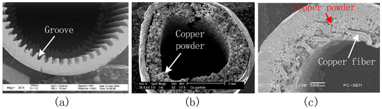
Figure 1.
Different wick structures of traditional heat pipes (a) groove, (b) copper powder sintering and, (c) compound types of wick structures.
The grooves are directly machined in the inner wall of the heat pipe, and they are open and have uniform cross sections, leading to the problem of insufficient capillary pressure. On the other hand, the copper powder sintering wick structure has some shortcomings, such as a long liquid reflux path, large reflux resistance, and so on. When the heat pipe is placed at a normal working position (Figure 2), it can work at the design power under the assistance of gravity or the capillary force of the wick structure. However, when the position of the condenser is lower than that of the evaporator (under anti-gravity heating conditions), the heat transfer efficiencies of the groove type, copper powder sintering type, and compound type of heat pipes will decrease dramatically, especially for the groove type heat pipe.
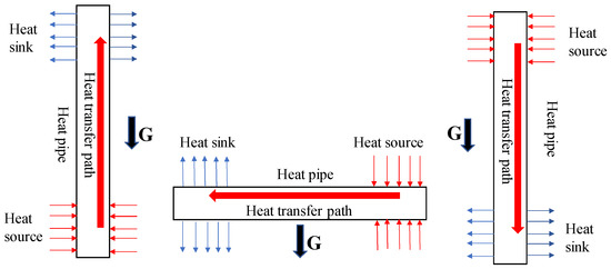
Figure 2.
Different positions of heat pipes when working.
Extensive research has been done to improve the thermal performances under anti-gravity conditions. Tang et al. [12] designed an anti-gravity loop heat pipe with a continued gradient porous wick structure with a height of 400 mm. When the heating power was 100 W, the thermal resistance was 0.24 °C/W and the maximum temperature of the evaporator was less than 105 °C. Jahan et al. [13] studied the effects of inclined angles and work fluid on the thermal performance of a heat pipe. Their result showed that the thermal resistance was sensitive to the working fluid and inclined angle. When the inclined angle was equal to 75°, the heat transfer performance was best. Wang et al. [14] fabricated and tested the thermal performance of a flat heat pipe with interlaced circular- and rectangular-groove wick structures. Experimental results showed that the best filling ratios were 65% and 70% and the corresponding thermal resistances were 0.183 K/W and 0.071 K/W, respectively. Deng et al. [15] studied an anti-gravity loop heat pipe with a bubbling generator. Their results showed that the anti-gravity loop heat pipe achieved a steady state in 20 min and that its thermal resistance was around 150 W/K under a heating power of 80 W. Hanlon and Ma [16] proposed a two-dimensional heat transfer model of a powder sintering wick structure. Their numerical results showed that the heat transfer ability was influenced by the diameter of powder, porosity, and the thickness of powder structure. Lips and Lefèvre [17] proposed a general analytical model for the design of conventional heat pipes. This model can be used to calculate the thermal resistance and the heat transfer limit, thus achieving the structural optimization of a heat pipe. Elnaggar et al. [18] established a two-dimensional model of the working fluid flow characteristics of a U-shape heat pipe in a vertical position and the natural and forced convection conditions. The temperatures of the evaporator, adiabatic section, and condenser and the velocity and pressure distributions of gas and liquid working fluids were analyzed. The results showed that under a heating power of 50 W, and a velocity of cooling air of 3 m/s, the thermal resistances under natural and forced convection conditions were 0.162 °C/W and 0.125 °C/W, respectively. Tang et al. [19] designed and fabricated anti-gravity heat pipes with an axially graded wick structure. Results showed that the critical heat load of an axially graded heat pipe was 75% higher than that of homogeneous wick heat pipes.
The existing studies are all based on a uniform phase-change chamber and wick structure. Little research could be found concerning the influences of a tapering column phase-change chamber and changeable cross-sectional wick structure on the thermal performance of a heat pipe. To overcome the drawbacks of the uniform phase-change chamber and the wick structure, a heat pipe with a tapering column cavity and changeable cross-sectional wick structure was designed and fabricated. The evaporator and condenser of this novel heat pipe have a changeable channel area, but unchanged mass flow; therefore, the velocity of the vapor remains constant, increasing the sound velocity limit of the heat pipe. Moreover, due to the flow area of the changeable cross section wick structure decrease, the pressure drop of the vapor decreases when flowing, and the vapor pressure is relatively large, which can keep the vapor retaining acoustic speed, increasing the viscous heat transfer limit of the heat pipe. To validate the above assumptions, the thermal resistance of the novel heat pipe in a vertical position was experimentally tested in this study.
2. Materials and Methods
2.1. Fabrication of Heat Pipe
The diameter and length of the heat pipe were 16 mm and 200 mm, respectively. The thickness of the copper tube shell was 0.3 mm. The wick structure with a changeable cross section was fabricated using a powder sintering process. Conical stainless steel rod served as the inner mold to fabricate the tapering phase change cavity. Three types of stainless steel molds, cylinder, blunt cone, and sharp cone, were fabricated by grinding process, and their dimensions are shown in Figure 3. Detailed fabrication processes of the anti-gravity heat pipe were as follows. The mold was initially inserted into the copper tube. Then, the copper powders (100-mesh) were filled in the gap between the mold and the copper shell. The resulting sample was sintered in a sintering furnace. After removing the stainless steel mold, the heat pipe was evacuated using the vacuum pump. Later, 2 mL of deionized water was injected into the cavity to serve as the working fluid. Finally, the anti-gravity heat pipe was sealed by argon-arc welding.

Figure 3.
(a) Structure and (b) dimension of different types of stainless steel molds.
2.2. Experimental Step
The test system contained the following parts: a heating module, a cooling module, two fixing clamps, thermocouples, a data acquisition card, and a computer (Figure 4). The heating module consisted of brass blocks and two heating rods. The heating rods were connected to a DC power supply (HSPY-30-05, Han Sheng Pu Yuan Technology Limited, Beijing, China), and the heating power could be calculated from the product of voltage and current. The cooling module was a cold-water bath system with a temperature of 30 °C. The thermocouples were inserted into the gap between the fixed clamp and the heat pipe to directly measure the temperatures of the evaporator and the condenser. The thermocouples were tightly attached to the surface of the copper tube under the pressure of a fixed clamp. Silicone grease conductive ointment was greased on the gap between the thermocouples and the copper heat pipe to decrease the thermal contact resistance. The temperature data measured by the thermocouples were collected by the multiplex temperature tester (TMP-16, VoInic, Hangzhou, China) and transferred to the computer.
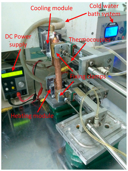
Figure 4.
Thermal performance test setup.
2.3. Data acquisition and Uncertainty Analysis
Neglecting the thermal contact resistance between the heat pipe and thermocouples, and ignoring the heat loss between the heat pipe and the environment, thermal performance of heat pipe can be characterized by thermal resistance Re (°C/W) as follows.
where Te and Tc are the temperatures of evaporator and condenser of the heat pipe, respectively. P is the heating power.
The uncertainty of the testing data mainly results from the heating module and the temperature data acquisition module. The maximum measure of the heating module is attributed to the DC power supply with a 0.05% voltage accuracy and 0.2% current accuracy. The measurement accuracy of the temperature data acquisition module was 0.02 °C and the T type thermocouples were calibrated with a measurement accuracy of 0.1 °C. The relative measurement errors of single-sample test [20] can be calculated as follows.
where E(y) is the measurement error of single-sample test, y and EXi are the given function, and the maximum measurement error of the independent variable xi, respectively. The maximum relative measurement uncertainty of the heating power is 0.21%. The relative measurement uncertainty of the thermal resistance ranges from 1.48% to 22.81%.
3. Results and Discussions
3.1. Wick Morphology and Structure Analysis
Morphologies of wick structures at the large and small ends of phase-change chambers are shown in Figure 5. The plot shows that the copper powders are intact and tightly sintered with each other. The small but integrated gaps between the copper powders provide microchannels for liquid reflux. The shape parameters of powders after sintering are shown in Figure 6 (where aspect ratio e is the ratio of the major axis (a) to minor axis (b) and the equivalent diameter de is the geometric mean of a and b). Figure 6a shows that the equivalent diameter (de) of powder ranges from 80 μm to 220 μm and the mean value is around 139 μm. Aspect ratio e of the powder ranges from 1.0 to 3.3 and its mean value is around 1.53, indicating that most of the powders are not present perfectly circular after sintering. The plot shows that the average perimeter of the copper powders after sintering is around 14.77% larger than that of the circular particles. In general, these non-circular particles have a relatively large perimeter compared to circular particles (Figure 6b) and they can provide additional microchannels due to the large number of pits on its surface. The additional microstructures have a relatively small radius of curvature and form a thin liquid film due to the small corners inside the microchannels, therefore significantly increasing the capillary force of the wick structure [21].
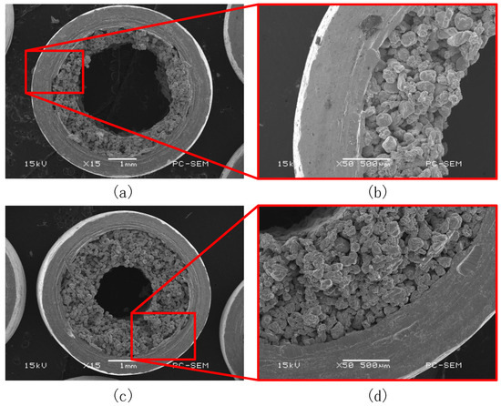
Figure 5.
Wick structure morphology of anti-gravity heat pipe; (a,b) large phase-change chamber end and (c,d) small phase-change chamber end.
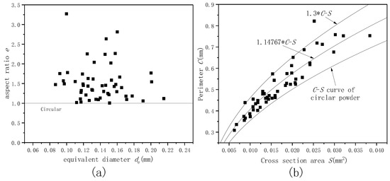
Figure 6.
Relation between (a) aspect ratio and equivalent diameter, and (b) perimeter and cross section area of copper powders within the sintering wick structures.
3.2. Thermal Resistance
Thermal resistances of different types of heat pipes are shown in Figure 7. The plot shows that thermal resistances of different heat pipes are less than 0.03 °C/W, except for the sharp conical chamber heat pipe under anti-gravity heating conditions (0.121 °C/W). When heating under the gravity assistance situation, the thermal resistance slightly increases and then decreases as the phase-changed chamber changes, in the order of uniform column, blunt cone column, and sharp cone column. Under anti-gravity heating conditions, the thermal resistance increases constantly as the phase-changed chamber changes, in the order of uniform column, blunt cone column, and sharp cone column. This phenomenon results from the thicker wick structure at the cooling end. Due to the gravity, the working fluid tends to priorly soak the bottom wick structure. Thicker film of condensed fluid directly increases the thermal resistance of the condenser and the whole heat pipe. It must be pointed out that the thermal resistance maintains a relatively low constant value, which may be attributed to the normal operation of all different types of heat pipes under these conditions.
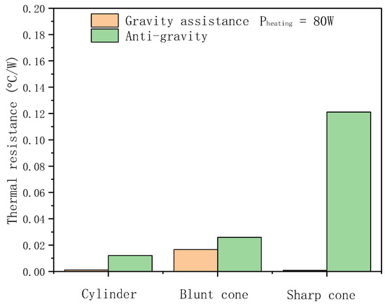
Figure 7.
Thermal resistances of heat pipes with different kinds of vapor chambers.
3.3. Start-Up Characteristic
Start-up characteristics of the different types of heat pipes are shown in Figure 8. The plot shows that the start-up time of a blunt conical chamber heat pipe is the best (3.67 min). The second-fastest heat pipe is cylindrical chamber heat pipe (3.83 min) and the slowest one is the sharp conical chamber heat pipe (4.89 min). Note that all start-up times of different types of heat pipes are similar and the temperatures will be steady within 3 to 5 min.
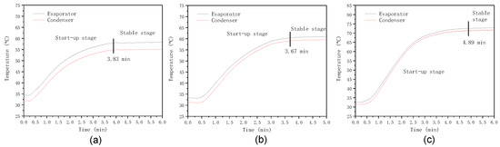
Figure 8.
Start-up characteristics of heat pipes with different kinds of vapor chambers (a) cylinder, (b) blunt cone, and (c) sharp cone.
3.4. Maximum Temperature
Maximum temperatures of the heating blocks cooling with different heat pipes are shown in Figure 9. The plot shows that under gravity assistance conditions, the maximum temperature is constant and then it dramatically decreases as the phase-changed chamber changes in the order of uniform column, blunt cone column, and sharp cone column. Under the anti-gravity heating conditions, the maximum temperature of heating block decreases and then increases as the phase-changed chamber changes in the order of uniform column, blunt cone column, and sharp cone column.
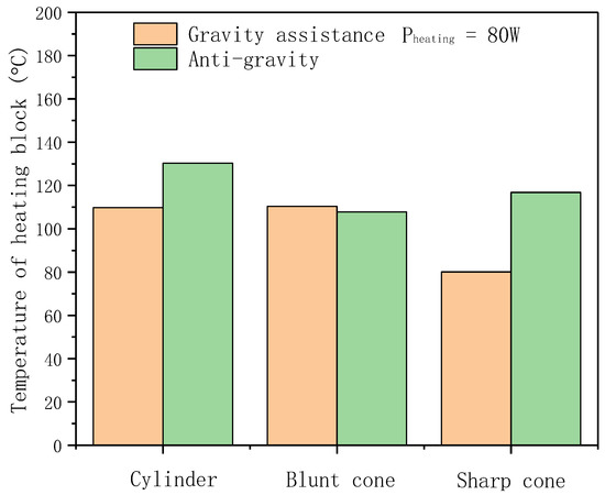
Figure 9.
Temperature of heating block.
Under gravity assistance heating conditions, the thickness of the fluid film in the evaporator increases for the conical chamber heat pipe, which slightly increases the thermal resistance of the evaporator. However, the heat transfer ability of the conical chamber heat pipe is still higher than that of the conventional one. This phenomenon may be attributed to the smaller interaction between the gas and liquid. In general, the gas will hinder the fluid in flowing back to the evaporator due to the gas flow direction, which is contrary to the fluid flow. For the conical chamber heat pipe, the hinder effect of the gas will be decreased, because the velocity direction of the gas near the gas–liquid interface is not parallel to the heat pipe and the magnitude of gas velocity decreases significantly as the channel diameter enlarges (Figure 10). Moreover, the area of the contact interface between the gas and liquid also decreases compared to a normal heat pipe. These effects simultaneously lower the fluid resistance induced by gas, finally increasing the heat transfer ability of the heat pipe with conical chamber under the gravity assistance heating condition.
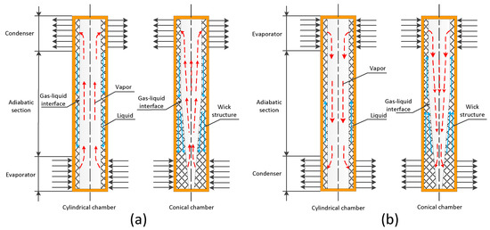
Figure 10.
Mechanisms of heat pipes with conventional and conical chamber under (a) gravity assistance heating condition and (b) anti-gravity heating condition.
Under the anti-gravity heating condition, the mechanism of the heat transfer of conical chamber heat pipe is more complicated. Figure 9 shows that the temperature of the heating block of the conical chamber heat pipe is still lower than the normal one. This phenomenon can be explained as follows. Firstly, vapor and liquid coexist in the heat pipe, and the temperature of the vapor is corresponding to its saturation pressure. Thus the trend of the temperature has a positive correlation to that of the pressure. Altering the temperature of tube wall is equal to changing the internal pressure of the tube. Similarly, the pressure is correlated to the velocity of vapor. Therefore, during the flow process of vapor, the velocity of vapor will reach acoustic velocity. For the traditional straight cavity heat pipe, the flow areas of the evaporator and the condenser keep constant, leading to the existence of sound speed limit. On the contrary, for the anti-gravity heat pipe, the flow area decreases from the evaporator to condenser, while the mass flow relatively keeps constant. Thus the speed of steam is basically stable and the value of sound speed limit will be increased. Secondly, when the heat pipe is started up below the sound speed limit, the density of the vapor is low. As the length of the tube increases, the effect of vapor viscosity is significantly larger than that of the inertial force, which may result in zero vapor pressure at the end of the heat pipe. In other words, the pressure difference is consumed by the friction loss of the viscous force of the steam flow. For the traditional heat pipe, the flow area keeps constant, leading to a large pressure drop. On the contrary, although the effect of viscous force of vapor still cannot be neglected, the pressure drop is small and the pressure in the condenser is relatively large due to the decrease of the flow area in the conical chamber heat pipe. Therefore, the speed of vapor can reach sound velocity, increasing the value of the steam pressure limit. Finally, the circulation of working fluid in the heat pipe depends on the capillary force of the wick structure. In the anti-gravity heat pipe, the circulation is driven not only by the capillary force, but also by the pressure of vapor in the condenser and the siphoning effect of evaporation in the evaporator. These three propelling powers drive the working fluid to move upward, keeping the working fluid circulating in heat pipe. Since the volume of conical wick structure is larger than the cylindrical one, the capillary ability of conical wick structure is also enhanced, increasing the working fluid circulating ability in the heat pipe.
Note that due to the unparalleled relation between the gas–liquid interface and the longitudinal direction of the heat pipe (Figure 10) and the increase of the gas velocity because of the decreased diameter of the gas chamber, the fluid resistance induced by gas significantly increases under the anti-gravity heating condition. Considering that the diameter of vapor chamber changes from d1 to d2, the velocity of the vapor can be calculated as follows when assuming that the flow remains constant.
The above equation shows that when the vapor chambers decrease, the velocity of vapor will increase significantly. This effect will hinder the flow back of liquid and impair the heat transfer ability of a conical chamber heat pipe, leading to the increased temperature of the heating block of the sharp cone heat pipe compared to that of the blunt cone.
Figure 9 also shows that the heat transfer ability of the conical chamber is always better than that of the cylindrical one. The performance of the sharp conical chamber heat pipe is the best under the gravity assistance heating condition. Contrarily, the blunt conical chamber heat pipe has the best heat transfer ability under anti-gravity heating condition. Interestingly, for the blunt conical vapor chamber heat pipe, the temperature of the heating block under gravity assistance heating condition is almost the same as that under anti-gravity heating condition, indicating that this type of heat pipe has a stable heat transfer capability. Its heat transfer capability is unaffected by the relative position of the heat and cold sources, which is suitable for the constant temperature cooling application of frequent switching of the heat and cold sources. The premise of normal working for the heat pipe is that the working fluid can realize a two-phase cycle. Therefore, the reasonable design of gas and liquid channels is essential. Our study clearly shows that tapering phase-change chamber with reasonable dimensions will increase the heat transfer ability of a heat pipe under anti-gravity conditions.
4. Conclusions
In this work, anti-gravity heat pipes with tapering column phase-change chamber and changeable cross-sectional wick structure were designed and fabricated. The thermal resistances of different heat pipes are less than 0.03 °C/W, except for the sharp conical chamber heat pipe under the anti-gravity heating condition (0.121 °C/W). Start-up times of all different types of heat pipes are similar and the temperatures will be steady within 3 to 5 min.
The heat transfer ability of the conical chamber is always better than that of the cylindrical one. The performance of the sharp conical chamber heat pipe is the best under the gravity assistance heating condition. Contrarily, the blunt conical chamber heat pipe has the best heat transfer ability under anti-gravity heating condition. Moreover, the heat transfer capability of the blunt conical chamber heat pipe is unaffected by the relative position of the heat and cold sources, which is suitable for the constant temperature cooling application of frequent switching of the heat and cold sources.
Author Contributions
Conceptualization, J.X.; methodology, X.-b.C. and H.Z.; validation, J.X. and J.H.; investigation, J.X.; resources, J.X.; data curation, J.X.; writing—original draft preparation, J.H.; writing—review and editing, C.Z. (Chunliang Zhang), C.Z. (Chao Zhou) and J.X.; supervision, J.X.; project administration, J.X.; funding acquisition, J.X. and J.H. All authors have read and agreed to the published version of the manuscript.
Funding
This research is supported by the National Natural Science Foundation of China (Nos. 51975135 and 51775122) and the China Postdoctoral Science Foundation (Nos. 2019TQ0180 and 2019M662242).
Conflicts of Interest
The authors declare no conflict of interest.
Nomenclature
| a | Major axis of the copper powder, μm |
| b | Minor axis of the copper powder, μm |
| d1, d2 | Diameters of vapor chamber at different locations, m |
| de | Equivalent diameter of copper powder, μm |
| e | Ratio of the major axis to minor axis of the copper powder |
| Exi | Maximum measurement error of the independent variable xi |
| E(y) | Measurement error of single-sample test, % |
| P | Heating power, W |
| Re | Thermal resistance, °C/W |
| Tc | Temperature of condenser, °C |
| Te | Temperature of evaporator, °C |
| V1,V2 | Velocities of the vapor before and after chamber changing, m/s |
| y | Given function of the independent variable xi |
References
- Xiang, J.; Zheng, H.; Wang, Y.; Zhang, C.; Zhou, C.; Chen, C. Numerical Simulation, Machining and Testing of a Phase Change Heat Sink for High Power LEDs. Materials 2019, 12, 2193. [Google Scholar] [CrossRef] [PubMed]
- Xiang, J.; Zhang, C.; Zhou, C.; Huang, J.; Liu, G.; Zhao, H. An integrated radial heat sink with thermosyphon for high-power LEDs applications. Heat Mass Transf. 2019, 55, 2455–2467. [Google Scholar] [CrossRef]
- Wang, G.; Quan, Z.; Zhao, Y.; Wang, H. Performance of a flat-plate micro heat pipe at different filling ratios and working fluids. Appl. Therm. Eng. 2019, 146, 459–468. [Google Scholar] [CrossRef]
- Ömür, C.; Uygur, A.B.; Horuz, İ.; Işık, H.G.; Ayan, S.; Konar, M. Incorporation of manufacturing constraints into an algorithm for the determination of maximum heat transport capacity of extruded axially grooved heat pipes. Int. J. Therm. Sci. 2018, 123, 181–190. [Google Scholar] [CrossRef]
- Kim, S.J.; Seo, J.K.; Do, K.H. Analytical and experimental investigation on the operational characteristics and the thermal optimization of a miniature heat pipe with a grooved wick structure. Int. J. Heat Mass Transf. 2003, 46, 2051–2063. [Google Scholar] [CrossRef]
- Jiang, L.; Tang, Y.; Pan, M. Effects of bending on heat transfer performance of axial micro-grooved heat pipe. J. Cent. South Univ. Technol. 2011, 18, 580–586. [Google Scholar] [CrossRef]
- Lee, S.; Lee, J.; Hwang, H.; Yeo, T.; Lee, H.; Choi, W. Layer-by-layer assembled carbon nanotube-polyethyleneimine coatings inside copper-sintered heat pipes for enhanced thermal performance. Carbon 2018, 140, 521–532. [Google Scholar] [CrossRef]
- Li, Y.; He, J.; He, H.; Yan, Y.; Zeng, Z.; Li, B. Investigation of ultra-thin flattened heat pipes with sintered wick structure. Appl. Therm. Eng. 2015, 86, 106–118. [Google Scholar] [CrossRef]
- Li, H.; Wang, X.; Liu, Z.; Tang, Y.; Yuan, W.; Zhou, R.; Li, Y. Experimental investigation on the sintered wick of the anti-gravity loop-shaped heat pipe. Exp. Thermal Fluid Sci. 2015, 68, 689–696. [Google Scholar] [CrossRef]
- Zhou, W.; Xie, P.; Li, Y.; Yan, Y.; Li, B. Thermal performance of ultra-thin flattened heat pipes. Appl. Therm. Eng. 2017, 117, 773–781. [Google Scholar]
- Li, Y.; Zhou, W.; He, J.; Yan, Y.; Li, B.; Zeng, Z. Thermal performance of ultra-thin flattened heat pipes with composite wick structure. Appl. Therm. Eng. 2016, 102, 487–499. [Google Scholar] [CrossRef]
- Tang, Y.; Zhou, R.; Lu, L.; Xie, Z. Anti-Gravity Loop-shaped heat pipe with graded pore-size wick. Appl. Therm. Eng. 2012, 36, 78–86. [Google Scholar] [CrossRef]
- Jahan, S.A.; Ali, M.; Islam, M.Q. Effect of Inclination Angles on Heat Transfer Characteristics of a Closed Loop Pulsating Heat Pipe (CLPHP). Procedia Eng. 2013, 56, 82–87. [Google Scholar] [CrossRef]
- Wang, C.; Liu, Z.; Zhang, G.; Zhang, M. Experimental investigations of flat plate heat pipes with interlaced narrow grooves or channels as capillary structure. Exp. Therm. Fluid Sci. 2013, 48, 222–229. [Google Scholar] [CrossRef]
- Deng, W.; Xie, Z.; Tang, Y.; Zhou, R. Experimental investigation on anti-gravity loop heat pipe based on bubbling mode. Exp. Therm. Fluid Sci. 2012, 41, 4–11. [Google Scholar] [CrossRef]
- Hanlon, M.A.; Ma, H.B. Evaporation Heat Transfer in Sintered Porous Media. J. Heat Transf. 2003, 125, 644–652. [Google Scholar] [CrossRef]
- Lips, S.; Lefèvre, F. A general analytical model for the design of conventional heat pipes. Int. J. Heat Mass Transf. 2014, 72, 288–298. [Google Scholar] [CrossRef]
- Elnaggar, M.H.A.; Abdullah, M.Z.; Abdul Mujeebu, M. Characterization of working fluid in vertically mounted finned U-shape twin heat pipe for electronic cooling. Energy Convers. Manag. 2012, 62, 31–39. [Google Scholar] [CrossRef]
- Tang, H.; Lian, L.; Zhang, J.; Liu, Y. Heat transfer performance of cylindrical heat pipes with axially graded wick at anti-gravity orientations. Appl. Therm. Eng. 2019, 163, 114413. [Google Scholar] [CrossRef]
- Moffat, R.J. Describing the Uncertainties in Experimental Results. Exp. Therm. Fluid Sci. 1988, 1, 3–17. [Google Scholar] [CrossRef]
- Lee, J.; Kim, S.J. Effect of channel geometry on the operating limit of micro pulsating heat pipes. Int. J. Heat Mass Transf. 2017, 107, 204–212. [Google Scholar] [CrossRef]


© 2020 by the authors. Licensee MDPI, Basel, Switzerland. This article is an open access article distributed under the terms and conditions of the Creative Commons Attribution (CC BY) license (http://creativecommons.org/licenses/by/4.0/).