Abstract
This paper suggests the reasonable switching frequency determination method for achieving highest efficiency of the railway propulsion system consisting the silicon carbide (SiC) inverter and permanent magnet synchronous motor (PMSM). The SiC power device allows increasing the switching frequency of the inverter because it has the small switching power loss. The total efficiency is taken into account for determining the switching frequency of SiC inverter in this paper. In the efficiency analysis of SiC inverter and PMSM, the PMSM drive control is considered with the hybrid switching method combined the synchronous PWM and asynchronous PWM. The result of the analysis shows the efficiency curve of propulsion system depending on the switching frequency. The switching frequency having the minimum power loss of propulsion system is selected based on the extracted power loss curve.
1. Introduction
Much research on the efficiency improvement of railway system has been performed for last decade [1,2,3]. In the railway vehicle, it has been trying to apply new technologies such as the permanent magnet synchronous motor (PMSM) and the silicon carbide (SiC) power device to the propulsion system. The PMSMs have 5–8% efficiency higher than induction motors [1,4], and SiC power devices reduce the switching loss to less than half loss of Silicon (Si) power device [5,6,7]. It is obvious that the propulsion system consisting the SiC inverter and PMSM, which is shown in Figure 1, guarantees the high efficiency.
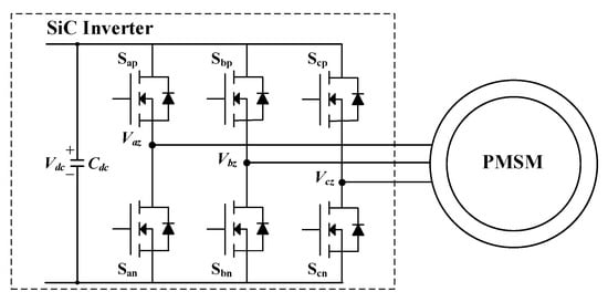
Figure 1.
Railway propulsion system consisting the silicon carbide (SiC) inverter and permanent magnet synchronous motor (PMSM).
In the railway industry, the induction motor has been selected as the traction motor for several decades [1,2,8]. The main reason is that the induction motor has the high reliability and superior maintainability beside it is inexpensive compared to PMSMs. However, since the totally enclosed structure improves the reliability and maintainability of PMSM, the number of the cases where the totally-enclosed PMSM is applied to the railway vehicle increases gradually [3,4,9,10,11,12,13]. In addition, the PMSMs show the higher efficiency than that of induction motor. Nowadays, the PMSMs have become attractive for railway operation company to save the operating cost. Along with the interest in PMSMs, the research on the PMSM drive control has been introduced in many paper [11,12,13,14,15,16,17,18]. The research theme in the railway vehicle can be divided into several areas: torque control, sensorless control, restarting control, and fault tolerant control. Nevertheless, these papers are based on the high efficiency operation of inverter. The existing PWM method for induction motor is applied to drive PMSM [13,14]. In the existing PWM method for induction motor, the six-step operation appears at propulsion inverter. Although the six-step operation has the large torque ripple, it is attractive PWM method to reduce the switching loss of power device.
Nowadays, the voltage class of SiC power module is announced to 3300 V [5,6,19]. Therefore, the studies applying the high voltage SiC power module into various applications are introducing in lots of papers [19,20,21,22,23,24,25,26,27,28,29]. The SiC power module with 1700 V class has been applied for the auxiliary converter of railway vehicle [20,25]. The switching frequency of 50 kHz is used in the resonant converter consisting 1700 V class SiC power module in [20]. In the catenary-free tram, the SiC power module with 1700 V class and hybrid SiC power with 1700 V class for the DC–DC converter used in the energy storage system are compared to Si module with 1700 V class [21]. Here, the switching frequency of 6 kHz in hybrid SiC power module has the same power loss with the Si module with the switching frequency of 2 kHz. The SiC power modules with various voltage classes have been considered in the traction inverter of railway vehicle [19,22,23,24,26,27,28]. Initially, the hybrid SiC power modules where the SiC freewheeling diode combines with silicon (Si)-IGBT were tested [19,22,23,24,26,27]. The mass and volume comparison results between the inverters consisting Si-IGBT modules and SiC power modules in the same switching frequency, which is respectively low switching frequency, 800 Hz, are shown in [22,24,26]. The propulsion inverter consisting of the hybrid SiC power modules can decrease the mass and volume until 60% of the conventional Si-IGBT inverter. Nonetheless, it can lead to the power loss reduction of 35% compared to the conventional Si-IGBT inverter [24]. The full SiC power modules enhance the efficiency improvement of propulsion inverter [28,29]. Since the SiC power module with 1200 V class is applied in [28], the switching frequency could be increased to 10 kHz. Although the SiC power module with 3300 V class is used in [29], the number of switching pulse increases in only the synchronous mode of PWM method. Generally, in the railway application, the SiC power module has been used to reduce the mass and volume of inverter in keeping the switching frequency as low value.
In Figure 1, the efficiency of propulsion system is determined by each efficiency of the PMSM and the SiC inverter. This paper focuses on the switching frequency because the switching frequency can influence both efficiencies of PMSM and SiC inverter. The effect of switching frequency on both the induction motor and Si-IGBT inverter is introduced in [24,29]. Ref. [29] used the triple pulse PWM method instead of the six-step operation to increase the efficiency of induction motor. Ref. [24] has proved that the six-step operation aggravates the efficiency of induction motor.
This paper proposes the reasonable switching frequency determination method for achieving highest efficiency of the railway propulsion system consisting the PMSM and SiC inverter. The efficiency analysis is implemented by considering the existing PWM strategies which are introduced in Section 2 briefly. In the efficiency analysis, the efficiencies of SiC inverter and PMSM are calculated through the co-simulation of SiC inverter (PSIM software, Powersim Inc., Rockville, MD, USA) and PMSM (J-MAG software, JSOL Corporation, Tokyo, Japan) to consider the interaction of them. Simulation results are based on the determination of the switching frequency of SiC inverter [30,31,32]. Based on the power loss curve of the propulsion system, the switching frequency with highest efficiency can be determined for propulsion inverter.
2. PWM Strategy for SiC Inverter
This paper focusses on how to maximize the efficiency of propulsion system. Therefore, the PWM strategy for the SiC inverter is also aimed to achieve the high efficiency of the SiC inverter. The existing PWM strategy used in the propulsion inverter guarantees maximizing the efficiency of the SiC inverter [14]. This strategy uses not only linear voltage modulation but also over-voltage modulation and six-step modulation. These modulations can be classified by magnitude of Vo (|Vo|) and dc-link voltage (Vdc) [15]. Figure 2 shows the output voltage (Vo) of existing Si-IGBT inverter depending on speed of railway vehicle. By considering that the maximum speed is 80 km/h, the six-step modulation relatively appears at low speed. Even though the six-step modulation leads to large torque ripple with vibration, it is enough to be ignored in railway vehicle. The six-step modulation appears over half of whole speed range in the existing PWM strategy. It means that the switching loss of the propulsion inverter can be minimized. The conventional PWM methods [15,16] guarantee the ideal change between modulations as |Vo| increases or |Vo| decreases. Generally, the reference voltage without any change is used to generate the desired |Vo| in the linear voltage modulation where the Vo is lower than Vdc/(=0.5774 Vdc). However, in the over-voltage and six step modulations, the changed reference voltage is used to generate the desired |Vo|. This paper applies the existing PWM strategy for the SiC inverter.
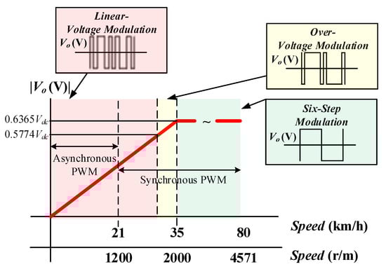
Figure 2.
The output voltage (Vo) of SiC inverter depending on the speed of railway vehicle.
The six-step modulation is not affected by the swishing frequency (fsw). The number of the switching is determined by only the fundamental frequency of Vo in the six-step modulation. Therefore, the inverter can show the same efficiency in six-step modulation regardless of fsw. In addition, the fsw is defined as K(integer) x the fundamental frequency of Vo in the synchronous PWM. It means that fsw is not changeable parameter and the efficiency is fixed as the same as that of six-step modulation if K is fixed. On the other hand, the variation of fsw influences the efficiency of inverter during the linear-voltage modulation in the asynchronous PWM. As fsw increases, the efficiency of inverter decreases. Consequently, it is needed to analyze the efficiency of propulsion system during the speed where the asynchronous PWM is applied.
3. Permanent Magnet Synchronous Motor Control
3.1. Permanent Magnet Synchronout Motor
This paper considers the 332-kW interior permanent magnet synchronous motor (IPMSM) as the traction motor for railway vehicle. Its specifications and cross section are shown in Table 1 and Figure 3. The B-H curves of materials (35PN230 and NdFeB) can be identified through the material datasheets. The lamination thickness of stator core and rotor core is 0.35 mm; the magnet is not laminated.

Table 1.
PMSM specifications.
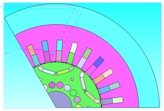
Figure 3.
The cross section of interior permanent magnet synchronous motor (IPMSM) used in this paper.
3.2. Control Method
Maximum torque per ampere (MTPA) operation is required to control the IPMSM. Lots of papers have suggested control methods for the MTPA operation [33,34,35]. This paper uses the current table-based control method [35]. The control block diagram is shown in Figure 4.
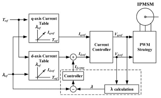
Figure 4.
Control block diagram for driving the IPMSM.
The d-axis current (Id,ref) and q-axis current (Iq,ref) are determined based on the MTPA tables according to the reference flux (λref) and reference torque (Tref), respectively. To eliminate the flux error, the compensation of the d-axis current (Id,comp) is used. To deal with the whole speed range with six-step modulation, the additional considerations (flux-weakening method and maximum torque per flux) should be reflected into the control method. However, this paper applies the simple control method of Figure 4 for the MTPA operation because the effect on the variation of fsw exists in the low speed range where the MTPA operation is needed.
4. Loss Analysis of Propulsion System
The loss analysis of the propulsion system can be divided into two parts: SiC inverter and IPMSM. Two parts affect each other as shown in Figure 5. The non-sinusoidal electromotive force of IPMSM affects the current control of IPMSM; therefore, it leads the low harmonics frequency components in the inverter currents. Finally, the low harmonics frequency components can increase the loss of IPMSM. In addition, the current ripple generated by fsw affects the power loss of IPMSM. Therefore, this paper conducts the loss analysis through the co-simulation between the SiC inverter (Power SIM software) and the IPMSM (J-MAG software) to consider the interaction of them. It is obvious that the simulation results are reliable in the comparison and analysis [30,31,32].
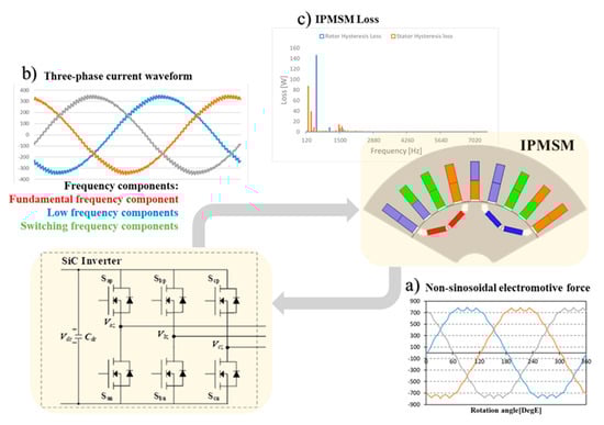
Figure 5.
Interaction between SiC inverter and IPMSM.
The loss analysis of propulsion system is implemented in the valid speed range (below 1200 r/m) where the effect of fsw variation exists.
4.1. SiC Inverter
The SiC inverter consists of six SiC MOSFETs. The 3300 V/800 A 2in1 SiC module where two SiC MOSFETs are connected to configure one leg, which is MSM800FS33ALT manufactured by HITACHI, is selected in this paper. The gate on and off resistances which decide Eon (Turn-on Loss per Pulse), Eoff (Turn-off Loss per Pulse), and Err (Reverse Recovery Loss per Pulse) are 1 Ω and 1.5 Ω, respectively. The additional data for power loss analysis of SiC MOSFET is shown in datasheet of MSM800FS33ALT. It is assumed that the SiC MOSFETs are closely connected to the DC-link capacitor to mitigate the effect of stray inductance enough [36,37].
The operation conditions of the propulsion inverter are as follows: Vdc is 1500 V, the control period is 1/(2xfsw), and Tref is 1522 Nm.
Figure 6 shows the three-phase current waveforms depending on fsw at 400 r/m. The |Vo| at 400 r/m is 188 V. The currents do not seem the completed sinusoidal waveform. There are several frequency components in currents: fundamental frequency component, low harmonics frequency components, and fsw components. Nevertheless, it is confident that as fsw increases, the current ripple caused by fsw is reduced.
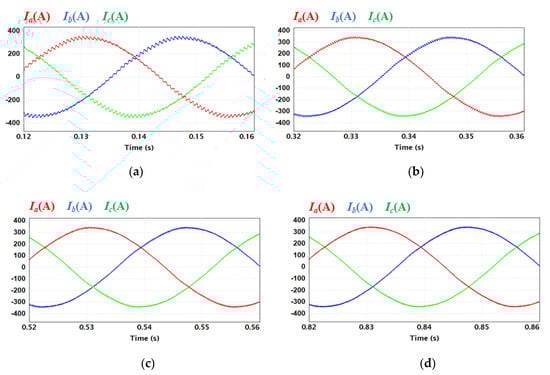
Figure 6.
Three-phase current waveforms depending on fsw at 400 r/m: (a) 750 Hz; (b) 1500 Hz; (c) 2250 Hz; (d) 3000 Hz.
Figure 7 shows the efficiency of one SiC MOSFET depending on the fsw and speed (r/m). Since the SiC MOSFET consists of MOSFET and Diode in one device, the loss analysis is implemented in two parts separately. As fsw increases, only the switching losses of MOSFET and Diode increase as shown in Figure 7a. One the other hand, the speed variation does not give enough impact on the total loss as shown in Figure 7b. The speed variation of IPMSM leads to the change of |Vo|. As the speed increase, |Vo| increases. The much current flows through MOSFET in the high |Vo| compared to Diode. It is identified that conduction loss of Diode is reduced as the speed increases.
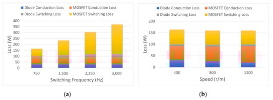
Figure 7.
Loss analysis of SiC MOSFET depending on fsw: (a) 400 r/m; (b) 750 Hz.
Figure 8 shows the total loss of SiC inverter depending on fsw. The inverter loss at 3000 Hz is more than twice inverter loss at 750 Hz. In terms of SiC inverter, the low fsw is required to reduce the power loss.
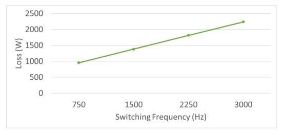
Figure 8.
Total loss of SiC inverter depending on fsw.
4.2. IPMSM
The finite elements method (FEM) model of IPMSM, which is Figure 9, is developed to analyze the power loss of IPMSM. The currents with ripple components of Figure 6 are injected to IPMSM through the co-simulation to reveal the effect of current ripple components on the power loss. The conditions for loss analysis are the same as those of loss analysis of SiC inverter. In the loss analysis, the electrical resistivity of NdFeB magnet is 1.80 × 10⁻⁵ Ω·m, which is used to analyze the eddy current loss of magnet. The phase resistance (Rcoil) of stator coil for the copper loss analysis is 0.021882 Ω. The iron loss of stator and rotor cores is estimated by applying the loss density curve of Figure 10.
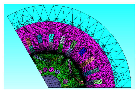
Figure 9.
The finite elements method (FEM) model of 322 kW IPMSM considered in this paper.
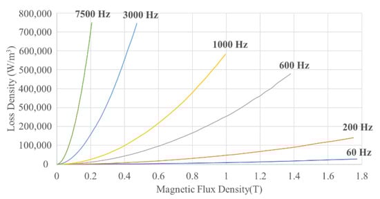
Figure 10.
The loss density of stator and rotor core material (0.35 mm) depending on the magnetic flux density.
To verify the estimated power loss of IPMSM from co-simulation, it is compared to the result of the power loss calculation equation. The loss components are divided into the coil copper loss (Pcopper), the core iron loss (Piron), and the magnet eddy current loss (Pm,eddy). In this paper, Pcopper and Piron are calculated and compared to estimated power loss from J-MAG software. Although Pm,eddy is not considered in the verification, the several researches have proved its accuracy [38,39,40].
To calculate Pcopper, the skin effect is ignored because the stator coil consists of many thin coils with the small dimension [41]. Therefore, Pcopper can be calculated as
The loss curve for Piron is often supplied by the core material manufactures [42]. The Piron is represented as
where fB is a frequency component of the magnet flux density and PLoss is loss density curve of Figure 10.
Figure 11 shows accuracy of the estimated power losses of IPMSM from J-MAG software and calculated power losses from (1) and (2). These values are expressed as per unit. Two copper losses are similar, and its error ratio is under 2%. In addition, the error ratio is about 5% in the iron loss comparison results.
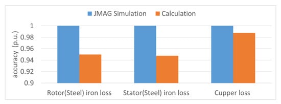
Figure 11.
Comparison of estimated power losses and calculated power losses.
Figure 12 and Figure 13 show injected currents and the power loss analysis result of IPMSM at 1200 r/m. The magnitude of current ripple is largest at fsw of 750 Hz and is smallest at fsw of 3000 Hz. The difference between current ripples at fsw of 2250 Hz and fsw of 3000 Hz is relatively small. The fsw over 2000 Hz has less impact on the current ripple as shown in Figure 12. The IPMSM power loss can be divided into four losses as shown in Figure 13. The stator winding has the copper loss. The steel, which is the material of the stator and rotor, results in the stator and rotor iron losses containing the hysteresis and eddy current losses. Only the eddy current loss is considered in the magnet. High fsw reduces the magnitude of current ripple as shown in Figure 12, and it mainly influences on the three losses such as stator iron loss, rotor iron loss, and magnet eddy current loss. Three losses decrease as the magnitude of the ripple current decreases. However, the effect of loss reduction is not large enough since fsw is about 2000 Hz. It can be estimated from the similar ripple currents of 2250 Hz and 3000 Hz. On the other hand, the copper loss does not have the enough impact by the variation of fsw.
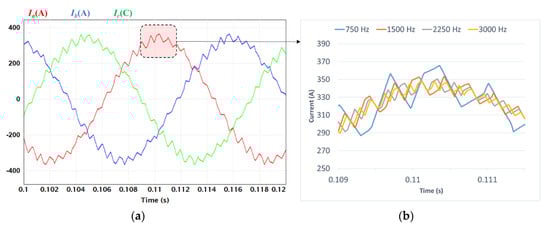
Figure 12.
The currents injected to IPMSM at 1200 r/m: (a) injected three-phase current at 750 Hz; (b) a-phase current depending on switching frequency.
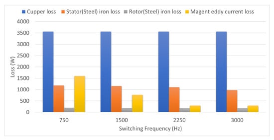
Figure 13.
The power loss analysis result of IPMSM at 1200 r/m depending on fsw.
Figure 14 shows the hysteresis losses of stator and rotor in the frequency domain depending on fsw at 1200 r/m. It is identified that the low harmonics frequency components are almost same regardless of fsw and fsw components have the different value each other. fsw of 750 Hz leads to the current ripple of 1500 Hz and its value is larger than that of 3000 Hz. Consequently, the high fsw reduces the power loss of IPMSM and it is opposite to the condition for the low power loss of SiC inverter.
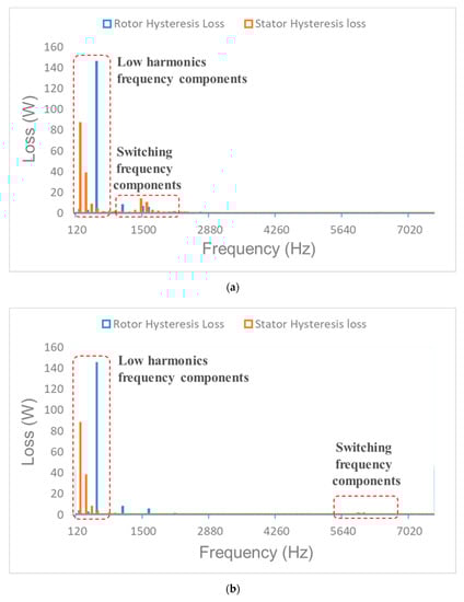
Figure 14.
The hysteresis losses of IPMSM in frequency domain at 1200 r/m: (a) fsw is 750 Hz; (b) fsw is 3000 Hz.
4.3. fsw Determination for Propulstion System
The power loss of propulsion system depending on the speed (r/m) of IPMSM can be represented by considering the results of Figure 8 and Figure 13. Figure 14 show the total power loss of the propulsion system. As mentioned in Section 4.1 and Section 4.2, the power loss of SiC inverter increases and IPMSM decreases as fsw increases. Figure 15 shows the individual power losses and the total loss. The total power loss curve of propulsion system has the minimum loss point between 750 Hz and 3000 Hz. This point is 2250 Hz and guarantees maximizing the efficiency of the propulsion system.
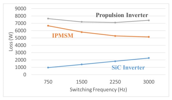
Figure 15.
The power loss analysis result of the propulsion system as 1200 r/m.
Figure 16 shows the total power loss of propulsion system depending on speed (r/m). The fsw for the minimum loss point at 400 r/m, 800 r/m, and 1200 r/m is 750 Hz, 1500 Hz, and 2250 Hz, respectively. The power loss of IPMSM at the low speed is small relatively compared to the power loss of SiC inverter. It means the power loss of SiC inverter is dominant at low speed. Therefore, as the speed increases, fsw for the minimum loss point increases. In addition, it can be estimated that the switching frequency upper than 3000 Hz aggravates the power efficiency of propulsions system under 1200 r/m.
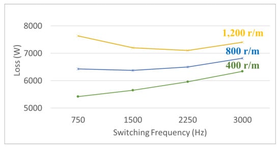
Figure 16.
The total power loss of the propulsion system depending on speed (r/m).
5. Conclusions
This paper determines the switching frequency (fsw) guaranteeing the minimum power loss of the propulsion system consisting SiC inverter and 332 kW IPMSM. The co-simulation was implemented and the effect of the low harmonic frequency and fsw components was reflected in the power loss analysis. As fsw increases, the power loss of SiC inverter increases because the number of switching increases, but the power loss of IPMSM decreases because the magnitude of current ripple caused by fsw is reduced. In addition, it was identified that as the motor speed increases, fsw for maximum efficiency operation of propulsion inverter, increases.
The implemented process suggests that both inverter and IPMSM should be considered in determining fsw of inverter to maximize the efficiency of the propulsion system. If the switching device or IPMSM specification is changed, the results of Figure 16 are not valid. However, it is important and meaningful that fsw can be determined through the process implemented in this paper.
Author Contributions
Conceptualization, project administration, writing—original draft preparation, J.-H.R.; data curation and software, J.-H.L.; supervision and writing—review and editing, J.-S.L. All authors have read and agreed to the published version of the manuscript.
Funding
This work was supported by the Railroad Technology Research Program through the Ministry of Land, Infrastructure and Transport of Korean Government under Grant 20RTRP-B146008-03.
Conflicts of Interest
The authors declare no conflict of interest.
References
- Ronanki, D.; Singh, S.A.; Williamson, S. Comprehensive Topological Overview of Rolling Stock Architectures and Recent Trends in Electric Railway Traction Systems. IEEE Trans. Transp. Electrif. 2017, 3, 724–738. [Google Scholar] [CrossRef]
- Yang, X.; Li, X.; Ning, B.; Tang, T. A Survey on Energy-Efficient Train Operation for Urban Rail Transit. IEEE Trans. Intell. Transp. Syst. 2016, 17, 2–13. [Google Scholar] [CrossRef]
- Diao, L.-J.; Tang, J.; Loh, P.C.; Yin, S.; Wang, L.; Liu, Z. An Efficient DSP–FPGA-Based Implementation of Hybrid PWM for Electric Rail Traction Induction Motor Control. IEEE Trans. Power Electron. 2018, 33, 3276–3288. [Google Scholar] [CrossRef]
- Shikata, K.; Kawai, H.; Nomura, H.; Aoki, H.; Fukasawa, S.; Tasaka, Y. PMSM propulsion system for Tokyo Metro. In Proceedings of the 2012 Electrical Systems for Aircraft, Railway and Ship Propulsion, Bologna, Italy, 16–18 October 2012; pp. 1–6. [Google Scholar] [CrossRef]
- Negishi, T.; Tsuda, R.; Ota, K.; Iura, S.; Yamaguchi, H. 3.3-kV All-SiC Power Module for Traction System Use. In Proceedings of the International Exhibition and Conference for Power Electronics, Intelligent Motion, Renewable Energy and Energy Management, Nuremberg, Germany, 16–18 May 2017. [Google Scholar]
- Mouawad, B.; Hussein, A.; Castellazzi, A. A 3.3 kV SiC MOSFET Half-Bridge Power Module. In Proceedings of the 10th International Conference on Integrated Power Electronics Systems, Stuttgart, Germany, 20–22 March 2018. [Google Scholar]
- Ke, H.; Chang, G.; Zhou, W.; Li, C.; Peng, Y.; Dai, X. 3.3kV/500A SiC Power Module for Railway Traction Application. In Proceedings of the International Exhibition and Conference for Power Electronics, Intelligent Motion, Renewable Energy and Energy Management, Shanghai, China, 26–28 June 2018. [Google Scholar]
- Skudenly, H.-C.; Weinhardt, M. An Investigation of the Dynamic Response of Two Induction Motors in a Locomotive Truck Fed by a Common Inverter. IEEE Trans. Ind. Appl. 1984, 20, 173–179. [Google Scholar] [CrossRef]
- Broche, C.; Lobry, J.; Colignon, P.; Labart, A. Harmonic reduction in DC link current of a PWM induction motor drive by active filtering. IEEE Trans. Power Electron. 1992, 7, 633–643. [Google Scholar] [CrossRef]
- Oh, S.Y.; Cho, S.-Y.; Han, J.-H.; Lee, J.; Ryu, G.-H.; Kang, D.; Lee, J. Design of IPMSM Rotor Shape for Magnet Eddy-Current Loss Reduction. IEEE Trans. Magn. 2014, 50, 841–844. [Google Scholar] [CrossRef]
- Zhang, H.; Liu, W.; Chen, Z.; Mao, S.; Meng, T.; Peng, J.; Jiao, N. A Time-Delay Compensation Method for IPMSM Hybrid Sensorless Drives in Rail Transit Applications. IEEE Trans. Ind. Electron. 2018, 66, 6715–6726. [Google Scholar] [CrossRef]
- Zhang, H.; Liu, W.; Chen, Z.; Jiao, N.; Zhao, D. Comparison analysis of low-switching-frequency-based IPMSM sensorless drives considering regulators, observer and inverter non-linearity. IET Electr. Power Appl. 2019, 13, 1022–1031. [Google Scholar] [CrossRef]
- Zhao, S.; Huang, X.; Fang, Y.; Zhang, H. DC-link-Fluctuation-Resistant Predictive Torque Control for Railway Traction Permanent Magnet Synchronous Motor in Six-Step Operation. IEEE Trans. Power Electron. 2020, 35, 10982–10993. [Google Scholar] [CrossRef]
- Liu, J.; Zhang, W.; Xiao, F.; Lian, C.; Gao, S. Six-Step Mode Control of IPMSM for Railway Vehicle Traction Eliminating the DC Offset in Input Current. IEEE Trans. Power Electron. 2019, 34, 8981–8993. [Google Scholar] [CrossRef]
- Kwon, Y.-C.; Kim, S.; Sul, S.-K. Six-Step Operation of PMSM with Instantaneous Current Control. IEEE Trans. Ind. Appl. 2014, 50, 2614–2625. [Google Scholar] [CrossRef]
- Bolognani, S.; Zigliotto, M. Novel digital continuous control of SVM inverters in the overmodulation range. IEEE Ind. Appl. 1997, 33, 525–530. [Google Scholar] [CrossRef]
- Yuan, G.; Hou, X.; Zheng, C.; Li, Z.; Yin, Y.; Liang, R. Restarting with speed for IPMSM based on hybrid synchronized PWM control schemes for rail train traction system. In Proceedings of the 2017 20th International Conference on Electrical Machines and Systems (ICEMS), Sydney, Australia, 11–14 August 2017; Institute of Electrical and Electronics Engineers (IEEE): Piscataway, NJ, USA, 2017; pp. 1–5. [Google Scholar]
- Wang, W.; Cheng, M.; Zhang, B.; Zhu, Y.; Ding, S. A Fault-Tolerant Permanent-Magnet Traction Module for Subway Applications. IEEE Trans. Power Electron. 2014, 29, 1646–1658. [Google Scholar] [CrossRef]
- Casarin, J.; Ladoux, P.; Chauchat, B.; Dedecius, D.; Laugt, E. Evaluation of high voltage SiC diodes in a medium frequency AC/DC converter for railway traction. In Proceedings of the International Symposium on Power Electronics Power Electronics, Electrical Drives, Automation and Motion, Sorrento, Italy, 20–22 June 2012. [Google Scholar]
- Wu, D.; Xiao, C.; Zhang, H.; Liang, W. Development of auxiliary converter based on 1700V/325A full SiC MOSFET for urban rail transit vehicles. In Proceedings of the IEEE Transportation Electrification Conference and Expo, Asia-Pacific (ITEC Asia-Pacific), Chicago, IL, USA, 22–24 June 2017; Institute of Electrical and Electronics Engineers (IEEE): Piscataway, NJ, USA, 2017. [Google Scholar]
- Helsper, M.; Ocklenburg, M.A. SiC MOSFET based Auxiliary Power Supply for rail vehicles. In Proceedings of the 20th European Conference on Power Electronics and Applications, Riga, Latvia, 17–21 September 2018. [Google Scholar]
- Rujas, A.; López, V.M.; Garcia-Bediaga, A.; Berasategi, A.; Nieva, T.; López-Martín, V. Railway traction DC–DC converter: Comparison of Si, SiC-hybrid, and full SiC versions with 1700 V power modules. IET Power Electron. 2019, 12, 3265–3271. [Google Scholar] [CrossRef]
- Rujas, A.; Lopez, V.M.; Villar, I.; Nieva, T.; Larzabal, I. SiC-hybrid based railway inverter for metro application with 3.3kV low inductance power modules. In Proceedings of the 2019 IEEE Energy Conversion Congress and Exposition (ECCE), Baltimore, MD, USA, 29 September–3 October 2019; Institute of Electrical and Electronics Engineers (IEEE): Piscataway, NJ, USA, 2019; pp. 1992–1997. [Google Scholar]
- Ishikawa, K.; Ogawa, K.; Yukutake, S.; Kameshiro, N.; Kono, Y. Traction Inverter that Applies Compact 3.3 kV/1200 A SiC Hybrid Module. In Proceedings of the International Power Electronics Conference, Hiroshima, Japan, 18–21 May 2014. [Google Scholar]
- Sugiyama, A.; Okitsu, H.; Ishimaru, T.; Kishimoto, Y.; Kadooka, S.; Sawakami, T. Verification Tests of 3.3kV SiC (Silicon Carbide) Hybrid IGBT Inverter for Nishi-Nippon Railroad Co., Ltd 3000 Series. In Proceedings of the International Conference on Electrical Systems for Aircraft, Railway, Ship Propulsion and Road Vehicles, Aachen, Germany, 3–5 March 2015. [Google Scholar]
- Makishima, S.; Fujimoto, K.; Kondo, K. The Direct Benefit of SiC Power Semiconductor Devices for Railway Vehicle Traction Inverters. In Proceedings of the International Power Electronics Conference, Niigata, Japan, 20–24 May 2018. [Google Scholar]
- Sato, K.; Kato, H.; Fukushima, T. Development of SiC Applied Traction System for Shinkansen High-speed Train. In Proceedings of the International Power Electronics Conference, Niigata, Japan, 20–24 May 2018. [Google Scholar]
- Yıldırım, D.; Akşit, M.H.; Yolaçan, C.; Pul, T.; Ermiş, C.; Aghdam, B.H.; Çadırcı, I.; Ermiş, M. Full-Scale Physical Simulator of All SiC Traction Motor Drive with Onboard Supercapacitor ESS for Light-Rail Public Transportation. IEEE Ind. Electron. 2020, 67, 6290–6301. [Google Scholar] [CrossRef]
- Kogure, H.; Ishikawa, K.; Kohno, Y.; Sakai, T.; Ishigaki, T. Development of Low Loss Inverter System Adopted Lower Harmonic Losses Technology and Ultra Compact Inverters Adopted High Power Density SiC Module. In Proceedings of the 20th European Conference on Power Electronics and Applications, Riga, Latvia, 17–21 September 2018. [Google Scholar]
- Bober, P.; Ferkova, Z. Comparison of an Off-Line Optimized Firing Angle Modulation and Torque Sharing Functions for Switched Reluctance Motor Control. Energies 2020, 13, 2435. [Google Scholar] [CrossRef]
- Nakata, T.; Sanada, M.; Morimoto, S.; Inoue, Y. Automatic Design of IPMSMs Using a Genetic Algorithm Combined with the Coarse-Mesh FEM for Enlarging the High-Efficiency Operation Area. IEEE Trans. Ind. Electron. 2017, 64, 9721–9728. [Google Scholar] [CrossRef]
- Di, C.; Petrov, I.; Pyrhonen, J.J. Modeling and Mitigation of Rotor Eddy-Current Losses in High-Speed Solid-Rotor Induction Machines by a Virtual Permanent Magnet Harmonic Machine. IEEE Trans. Magn. 2018, 54, 1–12. [Google Scholar] [CrossRef]
- Kwon, T.-S.; Sul, S.-K. Novel Antiwindup of a Current Regulator of a Surface-Mounted Permanent-Magnet Motor for Flux-Weakening Control. IEEE Trans. Ind. Appl. 2006, 42, 1293–1300. [Google Scholar] [CrossRef]
- Lai, C.; Feng, G.; Tjong, J.; Kar, N.C. Direct Calculation of Maximum-Torque-Per-Ampere Angle for Interior PMSM Control Using Measured Speed Harmonic. IEEE Trans. Power Electron. 2018, 33, 9744–9752. [Google Scholar] [CrossRef]
- Wu, J.; Wang, J.; Gan, C.; Sun, Q.; Kong, W. Efficiency Optimization of PMSM Drives Using Field-Circuit Coupled FEM for EV/HEV Applications. IEEE Access 2018, 6, 15192–15201. [Google Scholar] [CrossRef]
- Letellier, A.; Dubois, M.R.; Trovão, J.P.F.; Maher, H. Calculation of Printed Circuit Board Power-Loop Stray Inductance in GaN or High di/dt Applications. IEEE Trans. Power Electron. 2018, 34, 612–623. [Google Scholar] [CrossRef]
- Letellier, A.; Dubois, M.R.; Trovao, J.P.F.; Maher, H. Gallium Nitride Semiconductors in Power Electronics for Electric Vehicles: Advantages and Challenges. In Proceedings of the IEEE Vehicle Power and Propulsion Conference (VPPC), Montreal, QC, Canada, 19–22 October 2015. [Google Scholar]
- Liew, G.S.; Tsang, E.C.Y.; Ertugrul, N.; Soong, W.L. Analysis of a Segmented Brushless PM Machine Utilising Soft Magnetic Composites. In Proceedings of the 33rd Annual Conference of the IEEE Industrial Electronics Society, Taipei, Taiwan, 5–8 November 2007. [Google Scholar]
- Han, S.-H.; Jahns, T.; Zhu, Z. Analysis of Rotor Core Eddy-Current Losses in Interior Permanent-Magnet Synchronous Machines. IEEE Trans. Ind. Appl. 2009, 46, 196–205. [Google Scholar] [CrossRef]
- Chai, W.; Lipo, T.; Kwon, B.-I. Design and Optimization of a Novel Wound Field Synchronous Machine for Torque Performance Enhancement. Energies 2018, 11, 2111. [Google Scholar] [CrossRef]
- Gonzalez, D.A.; Saban, D.M. Study of the Copper Losses in a High-Speed Permanent-Magnet Machine with Form-Wound Windings. IEEE Trans. Ind. Electron. 2013, 61, 3038–3045. [Google Scholar] [CrossRef]
- Hargreaves, P.A.; Mecrow, B.C.; Hall, R. Calculation of Iron Loss in Electrical Generators Using Finite-Element Analysis. IEEE Trans. Ind. Appl. 2012, 48, 1460–1466. [Google Scholar] [CrossRef]


© 2020 by the authors. Licensee MDPI, Basel, Switzerland. This article is an open access article distributed under the terms and conditions of the Creative Commons Attribution (CC BY) license (http://creativecommons.org/licenses/by/4.0/).