1. Introduction
Aeroelasticity and stability analysis are interdisciplinary fields of study dealing with the interactions between aerodynamic forces and elastic structures for turbomachinery cascades, aircraft wings or wind turbine blades. The unsteady aerodynamics and structural dynamics result in a set of linear aeroelastic equations for 2D typical airfoil according to classical flutter theories, which are especially suitable for qualitative analysis of aeroelastic responses of large wind turbine blades. These aeroelastic equations can be easily solved in the time domain and are often used for exploring aeroelastic stability and dynamic responses to linear aerodynamic forces and other external excitations or random elastic excitations. Blade structures have always been modeled as a classical beam with bending and twist flexibility and involved in flutter in actuation of linear flow state with only a single 2D cross-section element extracted to simplify the research. Most 2D airfoil studies consider the mass-spring-damper system structure excited by some linear driving forces.
Manny scholars have adopted Euler or Navier-Stokes models based on computational fluid dynamics (CFD), panel method models based on boundary element flow model (BEFM) and other interaction models for unsteady flow modeling in turbomachinery cascades or wind turbine blades to study the aeroelastic stability for classical flutter. For instance, a surface singularity method similar to a panel method was used by Lei and Liang [
1] for cascade blade design and flow modeling for compressible inviscid flow in a 2D cascade. The classical flutter parameters in turbomachinery cascades, such as aerodynamic damping at different inter-blade phase angles, were estimated by Prasad and Pešek [
2] using a medium fidelity 2D flow solver. The flow solver was based on BEFM with unsteady potential flow described using a panel method. Coupling schemes using both explicit and implicit design and two turbulence models with wall functions and wall treatment, have been used in a Navier-Stokes CFD aeroelastic model to investigate classical flutter of wind turbine blade sections [
3].
A number of approaches have been developed to obtain the dynamic behaviors of aeroelastic systems with external excitations [
4,
5]. For example, Deng et al. [
4] investigated the aeroelastic stability of a 2D airfoil driven by a wideband noise excitation, in which the moment Lyapunov exponents were calculated via a stochastic averaging method. Liu et al. [
5] investigated the influences of random fluctuations on a 2D air-foil model with viscoelastic terms, and demonstrated the changes of plunge amplitudes and twist displacements in the process of external excitations.
The physical methods of flutter suppression for 2D blade section include all kinds of dynamic vibration absorbers (DVA) and external pitch control systems. For example, La [
6] proposed a simple semi-active DVA damping controller using Coriolis force to increase the energy dissipated by amplifying the DVA resonance motion. Kassem et al. [
7] established an aeroelastic mathematical model of a 2D airfoil equipped with DVA which was perfectly realized by experimental platform using a cantilever beam with a bonded macro-fiber composite and a lumped mass to suppress the aeroelastic motions.
Intelligent control theory has long been used in the control process of linear aeroelastic equations of 2D blade sections. Aeroservoelastic control based on theoretical pitch actuator was investigated to suppress the flutter of linearized aeroelastic system using proportional–integral–derivative controller and linear quadratic regulator [
8]. Model prediction control theories were thoroughly investigated to suppress the sectional vibrations of blades modeled as 2D pre-twist cross-sections that incorporated the structural damping [
9].
In the present study, classical flutter is investigated based on 2D blade section of wind turbine driven by unsteady aerodynamic forces. The 2D section exhibits bending and twist displacements excited by external pitch motion, hence, investigation and research on aeroelastic behavior of three degrees of freedom (3-DOF) blade are performed based on two types of HIC/LMI algorithms. We present an aeroelasticity analysis and real-time flow control scheme for 2D airfoil based on laboratory planning. The hydraulic transmission system not only simplifies the aerodynamic force, but also realizes the flow control, and it is very suitable for pitch control of large wind turbine blades. On the basis of intelligent control theory, not only the numerical simulation method of flutter suppression is realized, but also the matching and selection of controller hardware are realized through simulation, which is verified by the real-time hardware in the loop simulation platform using OPC technology.
The innovation of this study is as follows:
Real-time flow control and classical flutter are investigated based on 3-DOF blade section rather than conventional 2-DOF (elastic bending and twist displacements) airfoil. The real-time external pitch motion excited by HTS is added to the control strategies to suppress the bending/twist displacements.
The external pitch process is carried out through the rack-piston cylinder (RPC) that is driven by HTS, which provides the idea for the physical implementation of the theoretical pitch motion of 2D airfoil.
Due to the structural stability of HTS and the rigidity of rack bar, the lag items in aerodynamic loads can be omitted, a new applicable aerodynamic model is obtained, which can be applied to classical flutter analysis.
A novel HIC/LMI algorithm suitable for waveform tracking is used to configure the actuating signal of the proportional-flow valve (PFV) to track and adapt to the input cur-rent signal of PFV. Waveform tracking technology can lay a foundation of real-time realization for theoretical control algorithm matching and selecting appropriate hardware controller.
Due to the difficulty in performing wind tunnel tests of 2D airfoils, the effectiveness of intelligent control method based on flow control for 2D airfoil is difficult to test. In the present study, an online monitoring experimental platform using hardware-in-the-loop simulation, based on Siemens S7-200 PLC hardware and a Kingview detection system, is built to implement pitch control based on KOS communication and verify the feasibility of hardware implementation of the proposed control algorithms.
2. Airfoil Motion and Dynamics Analyses
Based on investigation of the classical flutter of 2-DOF section subjected to elastic bending/twist motions [
10], a set of 3-DOF non-dimensional aeroelastic equations integrated in external pitch motion are investigated to realize flutter suppression for wind turbine blades.
Figure 1 shows the coordinate system and the 3-DOF blade section. The origin of coordinate system is the aeroelastic center position of blade section which is fixed with a pinion. The elastic bending displacement is denoted by
; the elastic twist displacement is denoted by
; the pitch angle originated from external pitch motion is denoted by
. The external pitch movement is carried out by the rack bar ‘a-b’ by engaging with the pinion. The rack bar is connected and fixed to the right side of the piston rod of the RPC (See the following experiments). Aerodynamic lift and moment are denoted by
and
; pitch force and moment are denoted by
and
, respectively. Wind speed is denoted by
.
2.1. Aeroelastic System
Following the derivation of the 2-DOF motion equations of the classical flutter in Reference [
10], considering the external pitch effect (See Equation (7)) in the present study, the 3-DOF motion equations of blade section can be described as follows:
where
and
(
) are the normalized natural frequency and damping ratio;
is the rotation speed of the blade;
is chord length;
is the position vector.
is the average hydraulic driving force, and
is the corresponding mechanical efficiency;
is the radius of the pinion.
is the input signal requested by the hydraulic pitch system; it is exactly the output signal of PFV.
is the offset of hydraulic pressure determined by the input current range of PFV.
Using the Jones approximation of the Wagner function [
11], the aerodynamic loads were modeled assuming unsteady aerodynamics and were applied to the system using strip theory. Considering the structural stability of hydraulic transmission system and the rigidity of rack bar, the lag items in aerodynamic loads mentioned in [
11] can be omitted, so a new aerodynamic model can be obtained, which is suitable for wind turbine blade section in the present study. The new aerodynamic lift and moment,
and
, are described as follows:
where
is the semi-chord and
is the chord fraction by which the aerodynamic center lies forward of the elastic axis.
Merge the same items of variables in Equation (1), it results the following standard second-order differential equations as follows:
Assume
(herein,
), and rewrite Equation (4) into the first-order differential equation as follows:
where
,
,
.
2.2. External Pitch Motion
In order to investigate the potential for dynamic adjustment of the blade pitch, it is first necessary to improve the model with a real-time dynamic treatment. Generally speaking, there are two ways to deal with pitch motion in wind turbines under extreme conditions. One is to shut down the pitch movement directly in the case of an emergency, and the other is to adopt the form of automatic feathering type pitch motion that does not need external control, but realizes free pitch movement under the action of wind forces. The external pitch motion in the present study refers to the fully active pitch behavior implemented in the whole working condition, which is fully driven by the external controller and the pitch actuator. The real-time external pitch motion is carried out by hydraulic transmission system (see the schematic diagram of subsequent experimental platform). The hydraulic components and structures that drive pitch motion mainly include the hydraulic pump, PFV, RPC and displacement sensor used for estimation and measurement of pitch angles. The rack bar is connected and fixed to the right side of the piston rod of RPC, and drives the pitch motion by engaging the pinion. The specific work process is as follows:
The control algorithms are run in controller hardware system, outputting current signal;
Using the current signal to drive PFV valve, the valve core moves, the opening of valve port changes at the same time, causing the flow into the hydraulic cylinder to change, thus driving the piston of RPC to move;
When the piston moves, the rack on the right side of the piston rod engages with the pinion, thus causing pitch movement;
The sensor detects the changes of pitch angles in real time and feeds back the measured values to the controller hardware.
Hence, PFV and RPC are arranged in the forward branch of the control process, while the sensor is arranged in the feedback branch. According to the selection of practical components, by system identification, the transfer functions of these three core-components can be obtained. System identification can be investigated by the least squares algorithm based on the minimized sum of squared residuals [
12]. Therefor, the transfer functions of these three core-components can be described by a unified expression:
where
is the independent variable of Laplace Transform operation. The coefficients in the expression are listed in
Table 1.
The comprehensive system composed of the above three core-components is a high-order system which can be reduced to a second-order transfer-function structure suitable for pitch motion, according to the Optimal Hankel norm [
12], with the states corresponding to the smallest Hankel singular values discarded. Hence a new second -order transfer-function sytem for pitch motion can be obtained as follows:
Note that, at this time, the input of the system Equation (7) is a electric current signal
, and the output of the system is the pitch angle
. The former is exactly the input signal of PFV, and the latter is exactly the pitch angle signal of the airfoil. Furthermore, applying the Laplace Inverse Transform for this second-order transfer- function structure, the pitch actuation behavior can be described by a second-order differential equation model as:
where
is the input signal requested by the hydraulic pitch system mentioned above. Decompose Equation (8) into two expressions:
Equation (9) is exactly the expression of pitch motion implied in Equation (1), and another remaining expression is denoted by:
In order to facilitate the subsequent control analysis, Equation (10) is rewritten as the standard form:
3. Real-Time Flow Control Based on HIC/LMI
Considering the actual external pitch motion in engineering applications, as mentioned above, the control of aeroelastic system needs sufficient robust performance using a HIC controller. However, there are very few HIC algorithms that not only satisfy the control effects but also have the ability to configure controller hardware. The two HIC/LMI algorithms in the present study are exactly the algorithms [
13]. On the one hand, LMI is used to achieve robust performance, on the other hand, waveform tracking is used to realize the hardware configuration of the controller.
3.1. Aeroelastic System Control Based on the First HIC/LMI Algorithm
For system Equation (5), given the robust performance coefficient
, the existence of matrix
and
, is assumed, then according to Schur theorem, if the LMI inequality is satisfied [
13]:
Then the state feedback controller of
could be designed as:
where
.
The control objective is designed as follows. For arbitrary offset
(the offset of hydraulic pressure determined by the input current range of PFV), the robustness of the closed-loop system can be expressed as follows:
where the robust control parameter
is related to the control input signal, which is the factor affecting the control input;
is the robust performance parameter to be optimized.
The control output expression is:
Hence the controller satisfying Equation (16), can ensure the internal stability of the closed-loop system, and the controller satisfying the control objective design in Equation (14) can be obtained.
The solution of inequality Equation (12) is an optimization problem constrained by LMI. YALMIP, a toolbox of MATLAB codes (R2018a, MathWorks, Natick, MA, USA), can be used to simplify the solution process. On the basis of selecting the robust control parameter , optimizing the uncertain robust performance parameter , the controlled displacements and the control input can be kept within reasonable ranges.
3.2. Control of PFV Based on Another HIC/LMI Algorithm
in Equation (11) is the input signal requested by the hydraulic pitch system and exactly the output signal of PFV. To match the input current signal of PFV, Equation (11) is rewritten as new form withinput
as follows:
where
,
is the control target, then the controller is designed as:
Then the control objective is to make track the change rule of waveform of current signal by designing LMI and solving .
In the present study, a novel HIC/LMI algorithm suitable for waveform tracking is used to configure the actuating signal of PFV to track and adapt to the input current signal of PFV. The Lyapunov function is designed as follows:
where
. By the proper adjustment of
, the convergence effect of
can be effectively adjusted, and the solution of LMI can be obtained, then:
where
. Let’s assume
, then:
Suppose the control index of
is [
13]:
then:
Then, combining Equations (21) and (23), we can obain:
The integral of the above formula can be obtained:
Let
, then:
Then, the result of convergence of state variables can be expressed as: .
In addition, design of LMI can be described as follows. From Equation (25), we can obtain:
We apply a premultiplication operation with
in Equation (28), and suppose
, then the LMI design can be expressed as:
Then the effective controller can be obtained by solution of Equation (31). The , tracking the change rule of waveform of current signal , can be obtained by Equation (18).
4. Numerical Simulation
In order to investigate the potential for dynamic adjustment of blade pitch and test the effectiveness of pitch control algorithm mentioned above, some cases intended to highlight the pitch effects played by HTS will be presented. The related parameters of the sectional system, including the normalized structural parameters and external motion parameters are as follows: , , , , , , , , , , , .
In particular, due to the importance of PFV, for different types of PFV, the rated electric currents are different, so we choose two different valves with different rated currents as the research objects. In the first case, we choose the rated current range of 800 mA, then the offset of hydraulic pressure determined by the input current range of PFV is .
4.1. Motion of Divergent Instability
Figure 2 shows the simulation results of uncontrolled divergent, instable bending
twist
displacements of the blade section under condition of the pitch angle of
. It can be seen that in a very short time, the magnitudes of displacements increase to an incredible extent, which in fact means a state of divergent instability in numerical simulation. In practice, this means that the blade will break at this sectional position over time. Therefore, external pitch control is necessary, which is the goal of this design in the present study.
It should be stated that the wind speed is set to
in the present study, which is due to the fact that the wind speed acting on wind turbine is not more than
in the case of turbulence fractal characteristics within 80 m height [
14], when the turbulence intensity is constant and the surface roughness is specific. Therefore, the control methods proposed in the present study can be applied to the test of general wind turbines.
4.2. Illustration of Control Effects and Waveform Tracking
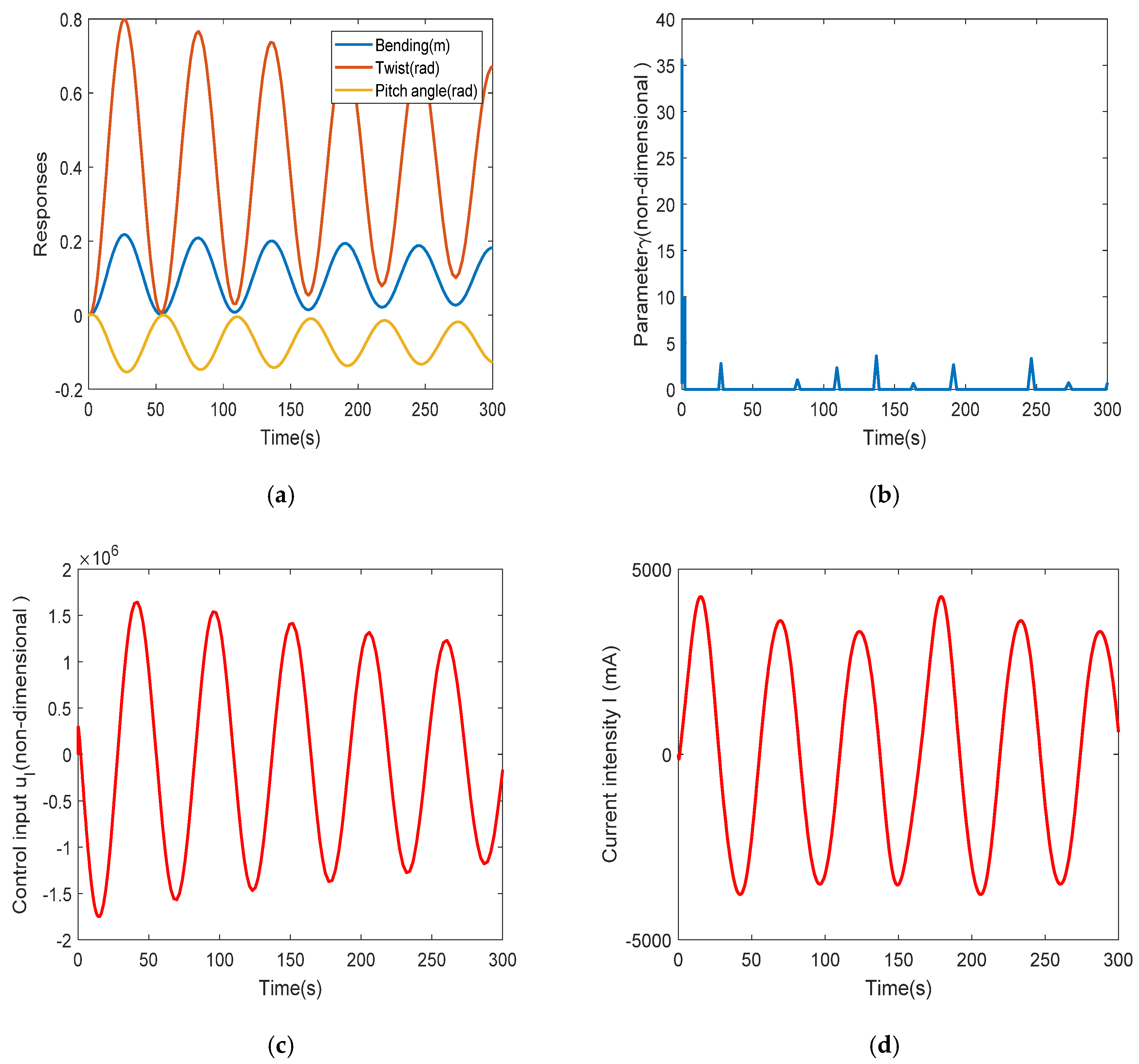
Figure 3 shows the controlled bending
twist
displacements as well as pitch angle
for driving, the fluctuation of robust performance parameters
, the control input signal
, the fluctuation of driving current signal
of PFV valve, and the tracking signal
in the second HIC/LMI algorithm. The control features can be summarized as follows: the amplitudes of the two controlled bending
twist
displacements are very small and shows states of convergence and stability, which show excellent control effects of the first HIC/LMI algorithm; the fluctuation range of pitch motion is very small, which shows good physical operability; the fluctuation range of robust performance parameters is not very large, which shows good robust performance; the driving current signal of PFV valve fluctuates within the rated range 800 mA, which shows the feasibility of simulation process; the waveform of tracking signal
(corresponding
) is completely consistent with that of current signal
, which shows the effectiveness of the second HIC/LMI algorithm. Waveform tracking technology can lay a foundation for theoretical control algorithm matching and selecting appropriate hardware controller. Its function is to combine the control algorithm with the hardware system, and decompose
into the conversion relationship of D/A module and the size of matching resistance (see
Section 5.2).
In order to test the universality of the HIC/LMI algorithms, the second case using PFV valve, with rated current being 5000 mA, is considered using the offset of hydraulic pressure .
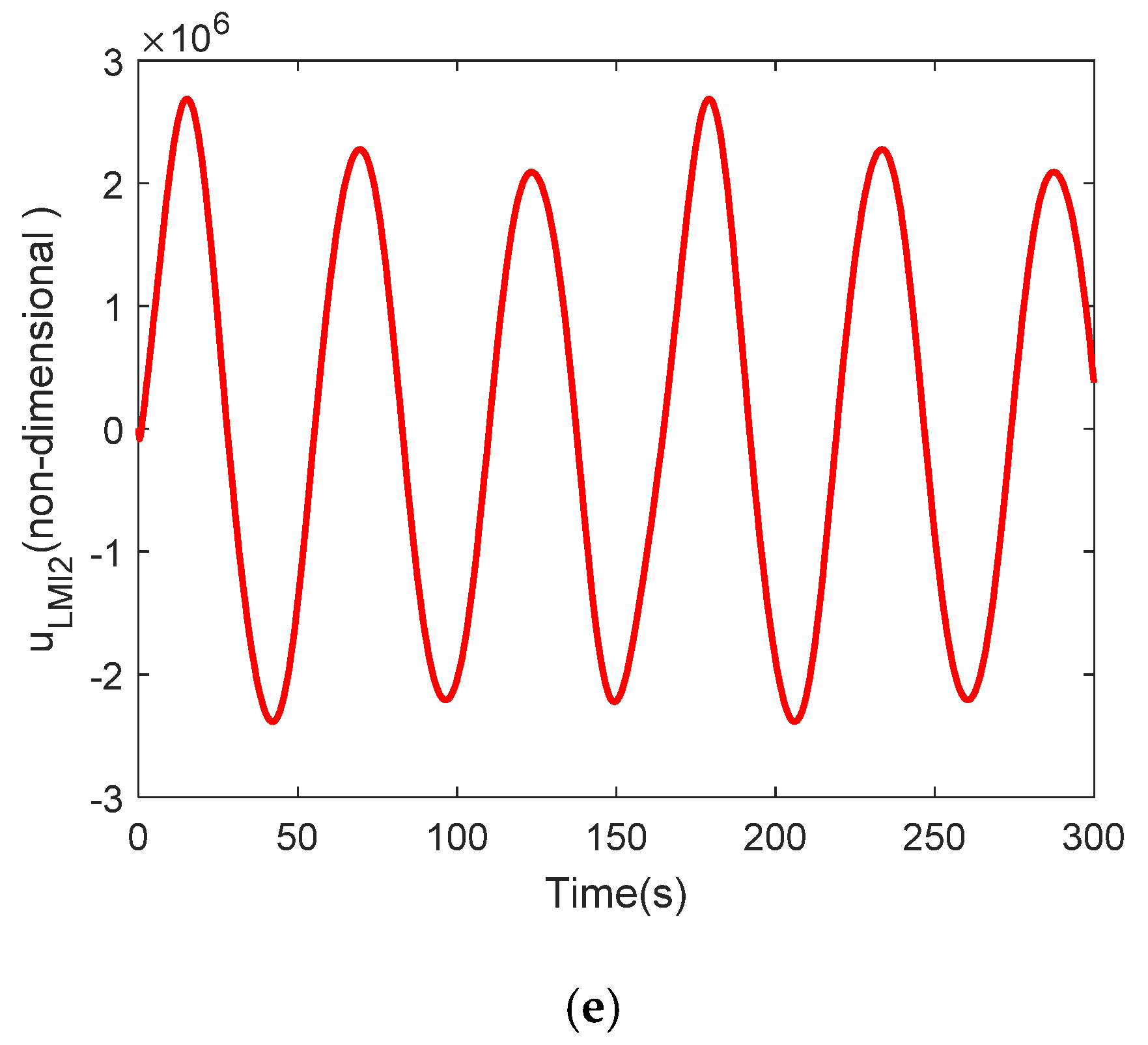
Figure 4 shows the controlled bending
twist
displacements as well as pitch angle
, the robust performance parameters
, the control input signal
, the driving current signal
of PFV valve, and the tracking signal
(corresponding
), under condition of
using the second case using PFV valve. It can be seen that we can almost draw the same conclusions as in
Figure 3, which further proves the universality of the HIC/LMI algorithms and can be applied to different hydraulic-control-valve structures. In addition, the overall fluctuation range of the robust performance parameter is smaller compared with that in
Figure 3, which shows better robust performance compared with the previous case, which also means that the greater the rated current of PFV, the stronger the robustness of the control system. Of course, in terms of the amplitudes of controlled displacements, compared with those in
Figure 3, the amplitudes of controlled displacements in
Figure 4 are relatively large, which also shows that the better robustness does not mean the better control effect. Robustness is the index of the feasibility and application range of the control algorithm, which represents the practical range of the control algorithm. But in any case, the control effect of each case is satisfactory, so the validity of the control algorithm is proved.
5. Experimental Platform for Real-Time Flow Control
An online real-time monitoring experimental platform using hardware-in-the-loop simulation, based on a Siemens S7-200 PLC controller system and a Kingview detection system [
15], is built to implement real-time pitch motion based on HTS and configure signal input of hydraulic PFV valve in pitch control.
5.1. The Experimental Platform Using Hardware-in-the-Loop Simulation
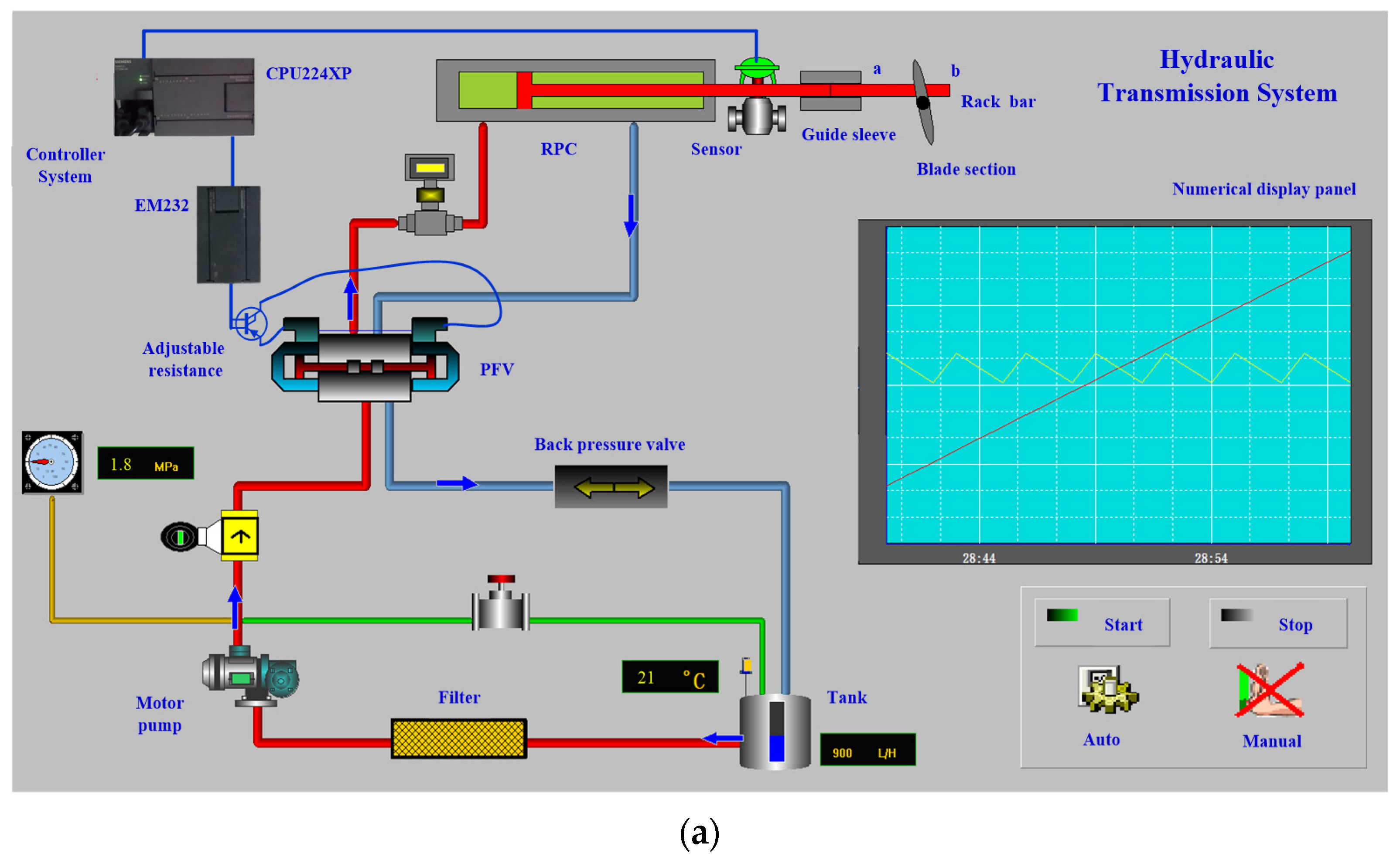
Figure 5a shows the experimental platform which is built to implement pitch motion based on HTS using a Siemens S7-200 controller system. The main components of HTS include a motor pump, PFV valve, RPC, etc. The Siemens S7-200 controller system includes a displacement sensor, controller CPU and a built-in A/D module, D/A module (EM232) and adjustable resistances.
Figure 5a is designed with the Kinview software which can monitor the operation of HTS and the S7-200 controller system online, with dynamic-signal fluctuations demonstrated in a numerical display panel. In
Figure 5a, the front end of the piston rod of the hydraulic cylinder is a rack bar. In fact, the piston rod and the rack bar are integrated. In order to ensure the stability of the rack bar movement, a guide sleeve is set at the front end of the piston rod. The guide sleeve is installed on the guide mechanism. When the piston rod moves, the rack bar also moves synchronously, and realizes meshing transmission with the pinion fixed on the airfoil, which is the external pitch motion. The specific working process of the hydraulic system using hardware-in-the-loop simulation is as follows:
The displacement sensor converts the pitch angle into displacement signal, which is fed back to the CPU through A/D module;
The above two HIC/LMI algorithms are executed in the CPU;
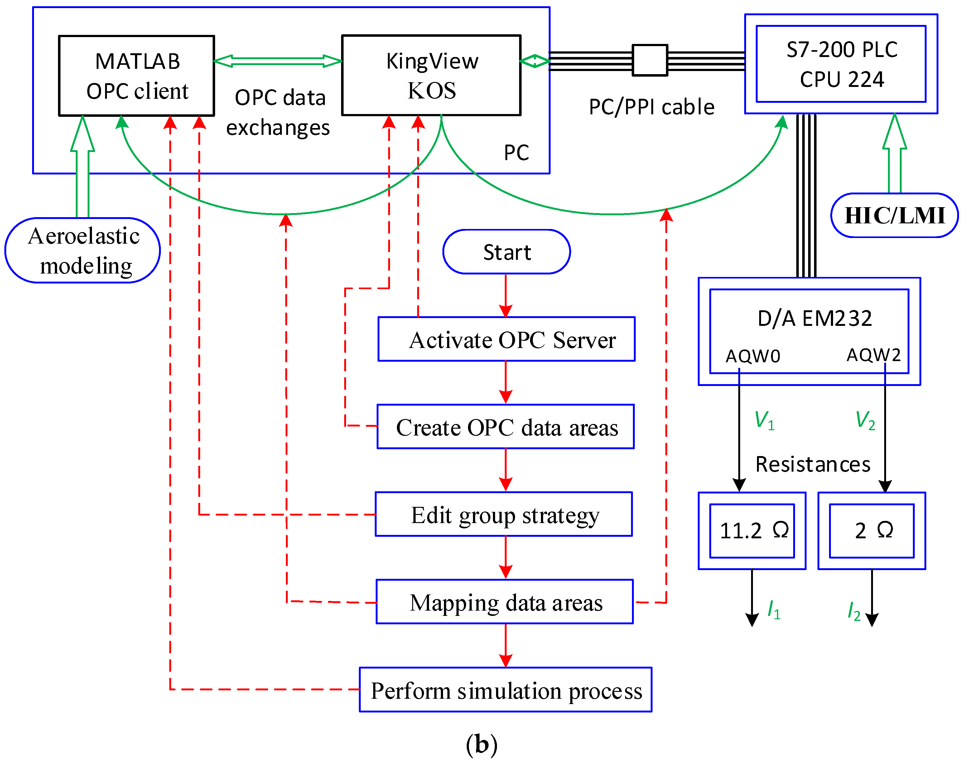
Aeroelastic system of Equation (5) runs in MATLAB simulation environment in PC, which communicates with controller CPU through Kingview. Illustration of online control based on the Siemens S7-200 controller system and workflow of Kingview communication is described in
Figure 5b;
After D/A conversion, the CPU inputs the current signal of analog quantity to PFV valve, which drives the piston movement of hydraulic cylinder and further completes the pitch behavior.
5.2. Illustration of Online Monitoring and Real-Time Configuration of the Controller Hardware
Figure 5b shows a illustration of the online control system based on a Siemens S7-200 controller system and the workflow of Kingview communication. The communication between S7-200 CPU and MATLAB environment is done by a Kingview OPC Server (KOS) [
16], and its specific execution process is shown in the red lines in
Figure 5b.
The current signals
, i.e.,
and
, in
Figure 5b are the driving signals that are input into the PFV, herein,
corresponds to the first type of PFV valve using
, and
corresponds to the second type of PFV valve using
. The acquisition of current signals needs a hardware configuration process using the acquired
and
which are exactly realized and obtained by the second HIC/LMI algorithm. The hardware configuration involves signal transmission from CPU to EM232, signal conversion and output of EM232, and configuration of resistances and its external circuits.
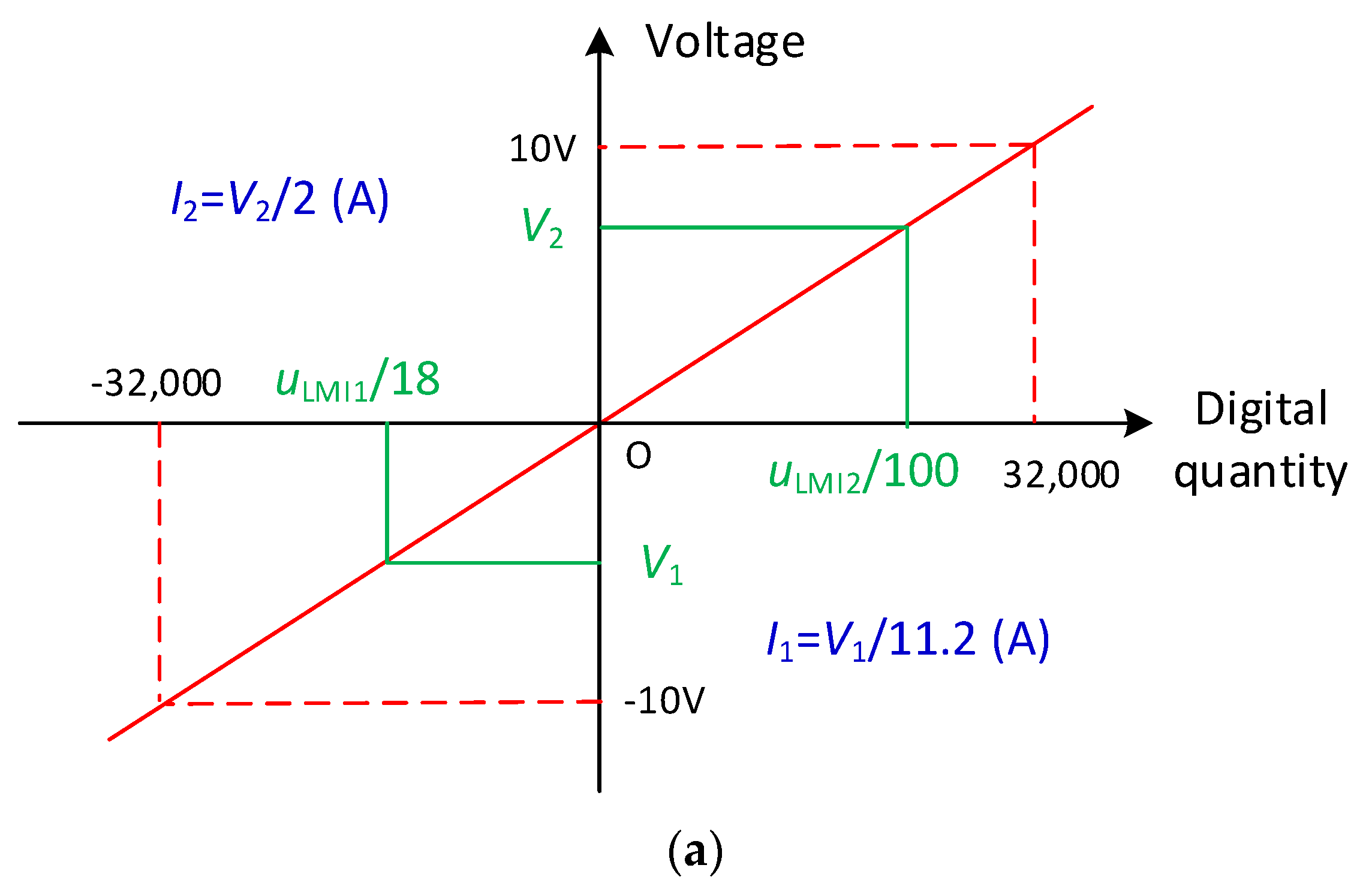
For example, in the first case of a PFV valve using
,
can be divided into two parts, which is
.
Figure 6a displays the output characteristic curve of EM232, of which the input digital-quantity range is [−32,000, 32,000]. Hence
, the purpose of which is exactly to limit the input within the range [−32,000, 32,000]. Meanwhile
is exactly the output voltage signal of PFV, and the other value
only needs to be configured as a resistance value to form a current signal, which is just the input control signal of the first type of PFV valve.
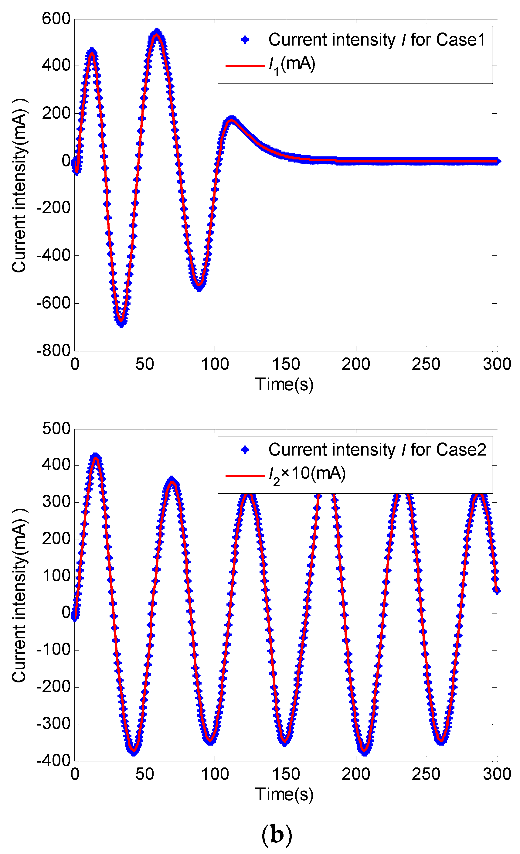
Figure 6b demonstrates, in two different cases of PFV valves, each comparison between the theoretical current signal from simulation marked by “blue dot” and the actual current signal processed by hardware configuration mentioned above that is marked by “red line”. Note that the theoretical current intensity values have been illustrated in
Figure 3 and
Figure 4, respectively. In each case, the theoretical value and the actual value are in perfect agreement, which verifies the effectiveness of the second HIC/LMI algorithm and the feasibility of the theoretical algorithm running in the hardware of the controller, and further proves the effectiveness of the hardware-in-the-loop-simulation platform used in the experiment.
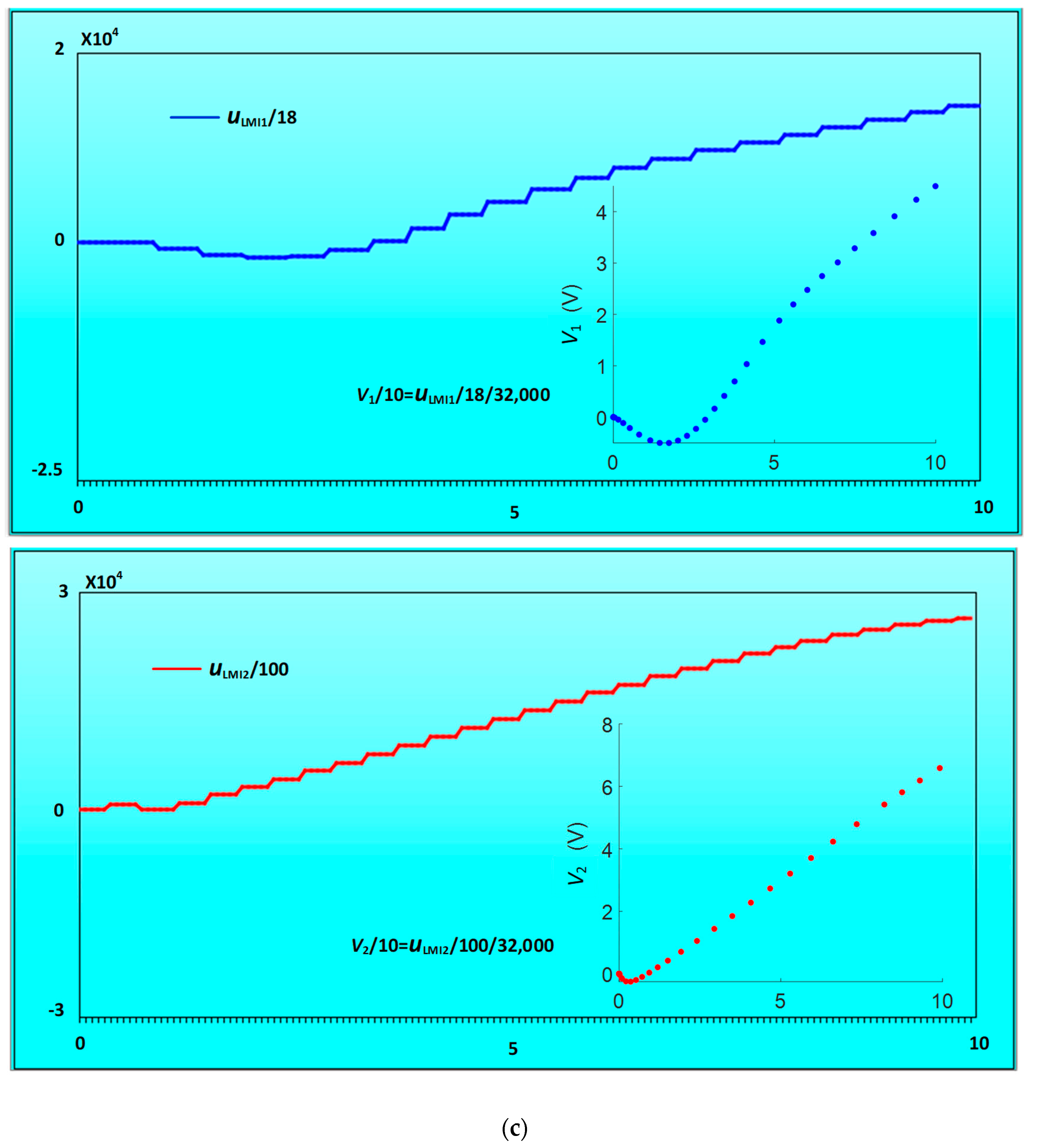
Figure 6c illustrates the dynamic-signal fluctuations of digital quantity in EM232 using numerical display panel in the Kingview detection system. In each case, the digital quantity (
for Case1;
for Case2) and the corresponding output voltage signals (
for Case1;
for Case2) can be displayed dynamically in real time. Because of the dynamic display of the panel to the signals, we can detect the ranges of the digital quantity and the ranges of the output voltage signals at each moment in real time. For example,
Figure 6c shows the operation results of digital quantity within 10 s, and compared those within 10 s in
Figure 6b, its fluctuation laws are completely consistent.
It should be stated that because the aeroelastic system model runs completely in the MATLAB environment, in order to ensure the flutter conditions in the experiment, we only need to detect the flutter wind speed through the wind speed sensor, then read it by the CPU module of PLC through the analog input module, and then send it to the aeroelastic system under MATLAB environment through KOS communication, and the simulation process of the aeroelastic system can be realized.
6. Conclusions
Vibration and real-time flow control of 2D blade section of wind turbine with 3-DOF, excited by external pitch motion using hydraulic transmission system, are investigated by numerical simulation and experimental test based on laboratory planning. The aeroelastic system combined with pitch motion is controlled by two types of HIC/LMI algorithms. Some concluding remarks can be drawn from the results:
The real-time external pitch motion is driven by RPC using HTS. The unsteady aerodynamic loads model is simplified by HTS. The HTS is actuated by the proportional-flow valve which is controlled by a novel HIC/LMI algorithm for waveform tracking that can be used for real-time configuration of controller hardware. The input current signal of PFV is realized by the configuration of Siemens controller system and its external circuits.
In two types of HIC/LMI algorithms, controller stabilities are affirmed using Lyapunov analyses, and controller values are derived and obtained by using LMI designs. Flutter suppression of divergent and instable displacements is shown, with obvious controlled effects and proper robust performance illustrated.
An online monitoring experimental platform, based on hardware-in-the-loop simulation, is built to implement pitch motion based on HTS and configure the signal input of a hydraulic PFV valve in pitch control. It verifies the feasibility of real-time hardware implementation of the proposed control algorithms. The data exchange between controller hardware and simulation environment is realized using KOS communication.
The hydraulic driving scheme and the proposed control algorithms, based on hardware-in-the-loop simulation platform in the present study, can be applied to large wind turbine blades with various airfoils.


