1. Introduction
Wind energy is one of the fastest growing renewable energy sources. Data from 2009–2019 indicates that global installed capacity increased by 409%, i.e., to a total of 651 GW in installed capacity as of 2019. Average yearly growth for the same time period is around 16.84% [
1]. Data for the Philippines from 2005–2018 shows that as of 2018 the Philippines had 426.9 MW of installed capacity for wind energy. Majority of the additions for the Philippines wind energy capacity came from 2014–2015 with the National Renewable Energy Plan foreseeing a total value of 2378 MW by 2030 [
2,
3]. Wind energy resource assessments showed that there are around 11,055 km
2 of land area that are rated good to excellent for wind energy use. Using conservative assumptions of about 7 MW/km
2, these areas could support more than 76,000 MW of potential installed capacity, delivering more than 195 billion kWh per year [
4].
Wind energy can be extracted from the air through the use of wind turbines. Wind turbines work by converting the kinetic energy in the wind as it flows into mechanical energy through the rotor, which is connected to the generator to produce electricity. A lot of effort has been put to improve the performance of wind turbines through modifying the turbine blade profile to increase the turbine’s efficiency. Instead of changing the blade profile, this study will modify the tip of the turbine blade by adding a structure called the split winglet, in an attempt of increasing the efficiency by improving the aerodynamics of the blade tip.
Winglets are structures attached to the tip of the wing that counter the drag created by wingtip vortices. These vortices form when the high-pressure air from the pressure side of the wing flows spanwise around the wingtip, moving toward the suction side of the wing. This flow creates a vortex rotating upwards and inwards toward the root of the wing as seen on
Figure 1. These vortices increase the drag by changing the wings’ lift backward, converting the usable lift force into drag. Winglets are small wing-shaped structures that generate lift perpendicular to the relative wind. When used in airplanes and similar applications, winglets reduce the induced drag at the wing tip. Winglets modify the direction of the relative wind at the wingtip by adding a component of wind that flows toward the root of the wing, resulting in a lift vector that has a component pointing forward. This forward lift counters the drag produced by the vortices at the tip of the winglet [
5].
Split winglets, as can be seen in
Figure 2, are simply a combination of a blended winglet and a wingtip fence. The lower winglet works in the same way as the upper winglet. In this study, the blade tip modification will be tested with both the single winglet and the split winglet and a comparison of the rotor performance will be presented.
Whitcomb, considered to be the father of winglet design, started his experiments on winglets in 1974 and later published his report in 1976. He found that the strength of wing tip vortices is reduced when a near vertical wing-like surface is attached to the wingtip [
7]. The application of such a wingtip device was still limited to aircrafts and has not been adopted in wind turbines until 1996 when Hasegawa et al. performed numerical simulations on wind turbines with winglets, using a vortex lattice method with a free wake model [
8]. Their calculations have shown a higher rotor power coefficient and a lower flap bending moment compared to a longer wing case. Johansen conducted three related studies regarding the application of winglets on wind turbines. The first one looked at the effects of winglets using computational fluid dynamics bending in upstream and downstream directions and of varying twist angle. (The upstream direction means that the winglet is facing against the flow of the wind.) Results showed that winglets increased power by around 1.3% for winds greater than 6 m/s but at the same time also increased thrust by around 1.6%. It also showed that upwind facing winglets performed better than the downwind facing counterpart [
9]. The second study looked at the effects of winglets by changing four parameters: winglet height, curvature radius, sweep and twist. The results showed that twist had a very little effect, a larger curvature radius decreased power gains, a sweep angle of 30° also decreased power gains and that winglet height influenced the performance of winglets the most wherein taller was better, although the author pointed out the challenge in the viability of such design due to the loads on the winglets [
10]. The last study looked at both the theoretical considerations and computational results on the nature of using winglets on wind turbines. The results showed that the increase in power that can be obtained with winglets was due to a reduction in tip-effects, and was not due to the shift in downwind vorticity due to downwind winglets. The numerical results, on the other hand, showed that downwind facing winglets performed better than upwind facing ones and that the power increase from winglets were smaller than simply extending the rotor blades, although shorter winglets <2% of the rotor radius came close to it [
11]. Elfarra et al. found that the k-ε Launder–Sharma turbulence model predicted power more accurately compared to Shear Stress Transport (SST) k-ω. Optimizations done showed that a cant angle of 84° and a twist of 2° for the winglets is the best shape for maximum torque. Results showed that the optimized winglets provided a boost of 9% in power and only a 1.3% increase in axial thrust [
12].
A similar study by Vasjaliya et al. used CFD for qualitative comparisons between turbine with and without winglets and wind tunnel testing on a scaled model for quantitative results. The qualitative comparison showed the vortices at the wing tips was split into two smaller vortices by the winglet, one at the wingtip and the other slightly away, in comparison to one large vortex of at the wing tip by an ordinary rotor blade. Quantitative results showed that on average the model with winglet generated 1.57% more power than the one without [
13].
In more recent years, though numerous studies have been carried out on the effects of winglets on wind turbine performance, very few tackle the problem of split winglets. In 2016, Nedyalkov et al. studied the effects of plain wing tip, generic winglet, and split winglet in tidal turbine blades [
14]. They conducted experimental and numerical tests on a model turbine and found that the split winglets have notably decreased the vortices formed at the tip. However, no significant increase in performance was observed. Pratilastiaro et al. carried out experimental tests on a wind tunnel scale wind turbine with and without winglets [
15]. Their study contradicts the current literature on the performance improvement effects of winglets. Their results showed a significant decrease in power coefficient when winglets were used. This effect was further studied by the same group when they conducted a numerical study on the same turbine and found that the blade with the split winglet produced a torque lower than that produced by the plain blade [
16]. They concluded that, in their tests, the device did not give a better performance.
It can be seen from the literature that in some studies the addition of the single winglet increases the power extracted in the wind turbines, but very few studies presented the effects of split winglets. In theory, the lower winglet works the same way as a single winglet, which can lead one to conclude that it can also affect the performance of the turbine in a positive way. This is the effect that this study wants to investigate—to compare the effect of a split winglet in a HAWT to that of a HAWT with no winglet and a HAWT with a single winglet through CFD. However, there is no consensus on the effects of split winglet in the performance of wind turbines. This is a strong justification that further studies on split winglets as applied to wind turbines must be carried out to provide significant evidence of its effects, positive or negative, on the performance of these energy conversion devices.
2. Methods
To conduct a CFD simulation to investigate the performance of a HAWT, a numerical mesh must be made first, with the wind turbine as the focus of the model. The rotor blade used in this study is based on the National Renewable Energy Laboratory Unsteady Aerodynamics Experiment Phase VI. NREL Phase VI involves large scale experiments conducted at the NASA Ames wind tunnel facilities. Among the series of tests and sequences, the blade from sequence H was selected as the baseline of this study [
17]. The experimental data was acquired from NREL through Mr. Lee Fingersh (personal communication, 19 September 2018) and used for validation and comparison purposes. The wind turbine is an upwind, 2-bladed HAWT and the blades are tapered and twisted. The wind turbine utilizes the NREL S809 airfoil section. Specifications can be seen in
Table 1.
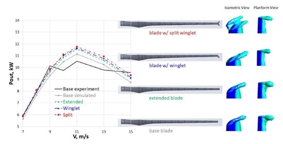
In this study, the blade was modeled using a computer aided design software by creating each airfoil section, and then using the loft command to create the body of the 3D model. Four different blade models were made in total—the base blade, an extended blade, the blade with winglet and blade with split winglet as presented in
Figure 3. Since the winglets add an additional 1.5% to the length of the blade, an extended blade was also modeled to account for the length difference. The blade models were then imported to Ansys Workbench (ANSYS Inc., Canonsburg, PA, USA) to produce the mesh that will be used for simulation. The imported blade model is then used as a reference to create the rotating domain, which was then further enclosed by a stationary domain in ANSYS Design Modeller (ANSYS Inc., Canonsburg, PA, USA). The rotating domain has a radius of 2 times and a depth of 2.5 times the blade length, while the stationary domain has a radius of 5 times and a depth 9 times the blade length.
In order to simplify the CFD analysis and to save computational resources, the domain was sliced in half and the core where the rotor hub is located was then hollowed out to create a 180° wedge model, using periodic boundary conditions on both ends of the domain. The model was then meshed using ANYS Workbench Meshing. The model was meshed using the curvature size function with relevance center set to fine. Minimum size was set to 2 mm while the curvature normal angle was set to 2.5 degrees. Growth rate was then set to 1.4. An inflation layer was also used. It contains five layers with a growth rate of 1.1 and a first layer thickness of 2.5 mm. The first layer thickness was calculated to have a y+ that stays within the 30–300 range. In addition to this setting, a few body-of-influence size functions were used to ensure that areas in the leading and trailing edge of the blade have a fine enough mesh. Match control was then used on the periodic surfaces. The resulting outer mesh is shown on
Figure 4a.
The converted mesh has 1.35 million cells with 6.14 million faces and 3.81 million nodes with a minimum orthogonal quality of 0.166 and a maximum aspect ratio of 39.82. The simulation uses a pressure-based steady-state Reynolds-averaged Navier-Stokes (RANS) solver. A steady-state solver was used to reduce computation time as early tests made using a transient solver did not appreciably differ from the steady-state solver. Both the stationary and rotational domain were set as fluid domains with standard air as fluid material. Turbulence model was set to Standard K-epsilon using an enhanced wall function after sample runs against realizable K-epsilon, Standard K-omega and K-omega SST have shown that Standard K-epsilon predicted power coefficient (CP) are the closest to the experimental data. Boundary conditions include non-slip walls for the surface of the rotor blade, slip walls for the inner and outer walls, periodic for the bottom surfaces, velocity inlet for the tunnel entrance and pressure outlet for the tunnel exit. Turbulence parameters was set to intensity and length scale with a value of 0.5% and 0.358 m. Mesh interface between the two domains is then set to periodic repeat. In the solution section, coupling scheme is set to “coupled” while discretizations were all set to second order to improve the accuracy of the solution. Solution controls are kept on their default values except for higher wind speeds where the courant was set 50 to aid convergence. A report definition to monitor the moment on the rotor blade along the axis of rotation was created. Simulations are deemed to be converged when residual values fell below 10−4.
3. Results and Discussions
The following are the results from the NREL phase VI sequence H experiment and from the simulation using Ansys Fluent of the four types of rotor blade modeled: base rotor blade, extended rotor blade, rotor blade with winglet and rotor blade with split winglet. Each rotor blade was run on seven different wind velocities, 7 m/s, 8 m/s, 9 m/s, 10 m/s, 11 m/s, 13 m/s and 15 m/s, totaling to 35 data points, 28 of which are simulated and 7 are data from the NREL phase VI experiment.
Wind power through a rotor disk (P) can be computed using the air density (ρ), wind velocity (V) and area of the rotor disk (A) as seen in Equation (1). The power coefficient (C
P), a non-dimensional number that represents the fraction of the power in the wind that is extracted by the rotor can then be computed by dividing the output rotor power (P
out) to P. Cp, however, has a theoretical maximum called the Betz limit, which is C
p,max = 16/27 due to the fact that not all the wind flowing through the rotor disk loses its kinetic energy upon contact. Similar to the power, the thrust on a wind turbine can be characterized by a non-dimensional thrust coefficient as seen in Equation (3) [
18]. Output rotor power for the simulated blades are obtained by converting moment obtained along the axis of rotation (M), which is equal to torque (τ) that is equal to power divided by the rotors’ angular velocity (ω) as seen in Equation (4).
Figure 5 shows how each of the simulated rotor blades can be compared to each other and how closely they follow the experimental data in terms of power generation. The simulated results closely follow the results from the experimental runs done by NREL on the phase VI sequence H experiment. Data from the simulated results of the base rotor blade show that P
out is within ±9% from the experimental results. The experiment values show a flattening of the power output from 9 m/s onwards. This behavior can be attributed to the turbine being a stall-regulated rotor with the performance limited to 10 kW.
The extended blade was added to eliminate the advantage gained by the blades with winglet and split winglet due to the increase in rotor disk area. Comparisons between the base and extended blades are made to ensure that the results are in line with the base blade. Pout increased on an average, across the seven wind speeds that were simulated, by 1.23% with the winglet and by 2.53% with the split winglet when compared with the extended rotor blade. The results show that the split winglet doubled the improvement in power generation brought by the winglet.
Calculating the CP for the wind turbine shows that the peak occurs on or before the 7 m/s wind velocity mark. It also shows the simulated results following the experimental results closely. Results from the base rotor blade compared to those of the extended one are generally within striking distance of each other with the average being only 0.21% higher and the largest gap being only 0.56% higher. Using the extended rotor blade as the basis for the other comparisons, on an average, the power coefficient of the rotor blade with winglet is 1.22% higher while the one with split winglet is 2.51% higher. The results show that the winglets increased the power production of the wind turbine by increasing its efficiency.
Additional runs were made to create a tip speed ratio sweep at V = 11 m/s. Data shows that the winglet and split winglet decreased the wind turbine’s performance at low tip speed ratios, tip speed ratio (tsr) less than 4.4. The impact of this decrease is minimal, however, on the total performance of the wind turbine, since at these tip speed ratios, the blade is generally at stall condition due to friction at the drive train or producing very little power. At higher tip speed ratios, tsr greater than or equal to 4.4, the winglet and split winglet started producing additional power as seen in
Figure 6.
Using a plane just behind the trailing edge of the tip of the rotor blade, the vortices formed at the tip can be seen by using line vectors representing the tangential wind velocity of the plane as shown in
Figure 7. Comparing the base and extended rotor blade, the results are generally the same for the two with the wind forming a swirling motion at the suction side of the rotor blade. Maximum tangential wind velocity is also practically the same with the only difference within 1–3% of each other. Looking at the winglet, the swirling motion of air, while still present, is not nearly as pronounced as that of the previous two rotor blades nor is it as close to the main body of the rotor blade. The maximum tangential wind velocity for the winglet is also around 10–20% lower than the previous two blades. Lastly, the results from the rotor blade with the split winglet shows similar results to the one with winglet wherein the swirling motion of the air is not as pronounced as the first two blades. The maximum tangential wind velocity for the split winglet is also similar to the one with winglet up to wind velocity of 11m/s after which it starts increasing more. The results show that the winglet and split winglet had quite a dramatic effect on the tangential wind velocity, lowering it by up to around 20%, and visually reducing the swirling motion at the suction side.
To help validate that the winglet and split winglet have indeed reduced the vortices at the blade tip, snapshots of the vortex core region using the swirling strength detection method using a level value of 0.01 was taken for comparison, which can be seen in
Figure 8. The effect of the winglet and split winglet to the vortices formed at the blade tip are immediately seen. The vortices formed at the tips of both the base rotor blade and extended rotor blade are remarkably larger at higher wind velocities than the other two rotor blades.
Looking at the pressure contour at the rotor blade tips,
Figure 9, the results for the base and extended blades are practically the same. For the blades with winglet and split winglet the low-pressure area at the suction side near the trailing edge is smaller in magnitude and intensity compared to the first two blades. Looking more at the split winglet, for the part that bends toward the pressure side, the high-pressure area at the leading edge shows greater intensity and magnitude compared to the other blades. Further, the low-pressure area in the pressure side is almost non-existent, and as for the part that bends toward the suction side, the pressure contour looks very similar to the blade with winglet with the exception of much smaller low-pressure area in the trailing edge. The results show that the winglet and split winglet significantly reduce the magnitude of the low-pressure area, caused by the wingtip vortices, at the trailing edge of the rotor blade tips that causes additional drag. In addition, for the blade with split winglet, the pressure difference on the left winglet (winglet closer to the pressure side) appears to be relatively bigger, suggesting good lift generation. The winglet near the suction side showed the same pressure contour as the blade with the single winglet configuration. Surface pressure contours on the rotor blades shows that pressure distribution across the blades are largely similar among the four blades simulated. There are small differences like the high-pressure area in the pressure side varying slightly in magnitude and intensity across the blades but nothing that immediately stands out. Most of the notable differences happened near the tip of the rotor blade.
To see the effect of the winglets, the results near the wingtip for the extended, winglet and split winglet blades were scrutinized. Looking at
Figure 10, at the leading edge, all four blade models followed the same pattern—big pressure difference between the pressure and suction side at the leading edge that tapers down. The change, however, occurs at x/c ≤ 0.5, where the pressure difference increases after that tapers off slightly again creating a hump instead of continuing to taper off. This shows the effect of the vortices at the blade tip as corroborated by
Figure 7 and
Figure 8. The formation of the vortices creates a low-pressure area, which further reduces the pressure at the suction side resulting to the low-pressure hump at x/c ≤ 0.5.
Comparing the extended and the blade with winglets shows two main differences. First, the pressure difference at the leading edge for the winglet is smaller than that of the extended. Second, the pressure at the suction side at x/c ≤ 0.5 for the winglet is not as low as that of the extended blade. This suggests that the winglet does not create additional lift at the wingtip but less drag is experienced at the trailing edge. Compared with the split winglet, the pressure side winglet’s pressure profile is quite similar to the results at 95% of the blade span of the base blade, suggesting good lift generation. In addition, the pressure difference at the trailing edge is smaller than even the one with winglet, suggesting reduced drag due to blade tip vortices. For the suction side winglet, the results follow the winglet pressure profile closely with the main difference that the low-pressure area does not go as low as that of the winglet, suggesting less lift generation compared to the one with winglet but also less drag due to blade tip vortices.
While the previous results have been largely positive, it can be seen that one of the side effects of having a winglet was the increase in thrust (T) at the wind turbine blades as presented in
Table 2. Using the extended rotor blade for comparison shows that the winglet increased thrust on average by 0.83% while the split winglet increased it on average by 2.05%. This increase in thrust therefore means that the rotor blade should have a more robust structural framework capable of handling the additional loads if a winglet or split winglet is to be used.
4. Conclusions
To extract as much potential as possible, there is a need to increase the wind turbines efficiency. One way of increasing the efficiency of wind turbines is by reducing the sources of drag and for wind turbines one such source are the blade tip vortices.
The study aimed to find out if the application of split winglets at the tip of HAWT blades would improve its aerodynamic performance, and the results showed that adding a split winglet to the NREL phase VI sequence H design can increase its power generation. Accounting for the difference in length due to adding a split winglet, power generation on an average increased by 2.53%. In comparison, a winglet that bends toward the suction side improves power generation on an average by 1.23%. Results also show that while winglets reduce performance at low tip speed ratios, the performance benefits at higher tip speed ratios where the majority of the power is generated more than make up for it.
The study also shows that the increase is achieved through two factors. First is that the winglet and split winglet drastically reduced the low-pressure area at the trailing edge of the blade tip that pulls back the blade, creating drag. This reduction in vortex core region was a result of the large drop in the tangential wind velocity going from the pressure to the suction side of the blade tip due to the winglets. Second is that the winglets themselves generate lift as can be seen on the pressure contour plot at the blade tip. The difference in pressure at the blade tip between the pressure and suction side responsible for creating lift is still present on the winglet and in case of the split winglet improved.
The results, however, are not all positive. One negative is that the winglets increased the thrust experienced by the rotor blade. Accounting for the difference in blade span of the base blade and ones with winglet, thrust increased by 0.83% and 2.05% for the blade with winglet and split winglet, respectively. This means that additional structural support is required to help support the additional load brought by the addition of winglet to the blade.
In the case of this study, attaching a split winglet to a wind turbine rotor blade increased power generation by a small but not insignificant amount. The study also showed that the split winglet is better than a winglet in increasing power generation. The opposite is true, on the other hand, in terms of the additional thrust experienced by the blade.


