Abstract
Configurations, coordinated controller design and applications of various off-grid systems with distributed energy resources (DERs) for an uninterrupted supply, are presented in this paper. The performances for the optimal operation of a diesel generator (DG) in the presence of nonlinear loads, fuel-savings, voltage and frequency regulation, a soft and secure transition among different operating modes, an optimization, and power management control, are validated through simulated results and test results on the prototype to demonstrate the suitability of these configurations with natural energy resources (NERs) for continuous development in remote as well as in isolated locations.
1. Introduction
Most of the remote and rural areas around the world rely on the diesel engine powered generators for their electricity needs. For example, the telecom industry in India uses 90,000 diesel generators (DGs) with annual fuel consumption that exceeds two billion liters [1], and in northern Canada, 176 of 251 communities are diesel-fueled with more than 90 million liters/year fuel consumption [2]. The diesel consumption is also high in isolated mine sites, water pumping stations, and petroleum platforms, etc. However, considering the fuel price and air pollution, the diesel generators (DG) are costly, pollutant, and inefficient as an energy source (ES), especially, when they supply electricity at light load conditions [3].
Many solutions are reported in the literature to reduce fuel consumption and to improve air quality [4,5,6,7,8]. Unfortunately, these studies are limited to the economic study, no real technical solution is detailed and implemented. Moreover, the performance of DG in the presence of disturbances has not been considered. The generated power from the distributed energy generation (DES), has enhanced after a breakthrough development in power converters, machines, and digital controllers. Moreover, off-grid systems with natural energy resources (NERs) are expected to reduce the use of fossil fuels and the vulnerability of remote areas to electricity price volatility [9]. Unfortunately, NERs are stochastic and limited in their availability across space and time. Therefore, a combination of available renewable resources, DG, the battery energy storage (BES) along with optimum control strategy, is required to ensure uninterrupted power supply in remote areas. Recently, many types of research work in the design and control of off-grid systems are reported in the literature [10,11,12,13,14,15,16]. In [10], the off-grid hybrid wind-PV system is proposed, and in [11,12], wind-PV-pico-hydro, wind-diesel hybrid power systems are suggested to minimize the use of DG. New solutions for the optimal integration of solar photovoltaic arrays (SPVA) with existing DGs in remote areas are presented in [13]. A hybrid power system is reported for isolated mine sites in [14,15,16], multiple microgrid systems are proposed for isolated areas.
In the off-grid system, the load requirements decide the size of system components, whereas, availability of NERs decides the appropriate configuration. Generally, in off-grid systems, the NERs are linked to the AC bus so that available AC power system standards are used in the design, control, as well as for the protection of the technology. On the contrary, the utilization of DC bus in off-grid systems is not picking-up due to the non-availability of standard products and protection issues [17]. However, the synchronization and inrush currents caused by transformers, AC motors, and generators, and difficulty in voltage control and system stability are the main challenges in the AC bus contrary to the DC bus. Besides, the DC bus in off-grid systems allows for efficient integration of NERs and storage systems through reduced power converters, which help to reduce the oscillations in voltages and currents [18,19]. Therefore, off-grid systems always have a combination of AC and DC generation and conversion to AC at the point of common coupling (PCC) for feeding AC loads [20,21]. Further, the reported research on power control and management is presented in [22,23,24,25,26,27], an application of NERs combinations in [28], the controller design, and the stability analysis strengthening off-grid configurations are detailed in [29,30,31,32]. The effective control is required to operate various power converters and generators at maximum efficiency to extract the utmost power from NERs, as and when available. For NERs, such as wind turbine (WT) and micro-hydropower (MHP) based on electrical machines, power electronic devices are required to get high performance and connect them to the PCC. The same technique is utilized for DGs to synchronize with the PCC and to achieve the desired performance. In the SPVA system, single and two-stage converter-based configurations are used to connect the SPVA to the PCC and to achieve maximum power point tracking (MPPT) [33,34]. A comparative study on existing MPPT methods is detailed in [35,36]. Among existing MPPT methods, the perturb and observe (P&O) technique is mainly employed due to easy implementation, but it suffers under rapid variation of sunlight. To solve this drawback, an improved P&O technique is presented in [37], and in [38], the sliding mode approach is suggested for MPPT of SPVA. Advanced control strategies are required to control voltage/frequency (V/f), to synchronize between available DES and PCC, and to ensure good power quality in the off-grid systems. For (V/f) control, the droop method is used in [39,40]. Furthermore, an adaptive and sliding mode controls are reported for the off-grid system in [41,42] to solve these issues. Two control strategies based on the predictive control with Clark’s transformation are presented to ensure regulation of (V/f) in an islanding mode and soft synchronization of DES with the PCC, in [43,44]. Regarding the minimization of diesel fuel of DG, high penetration of wind/diesel with compressed air energy storage is proposed in [45]. In [46], wind/PV/diesel with storage is proposed, and PV/diesel with storage is recommended in [47]. In these off-grid configurations, the storage is employed to minimize the use of fossil fuel as reported in the study made in [48,49]. In [49], 66 configurations based on two, three, and four DESs, are discussed. Based on this deep analysis of the different components of the off-grid system including control, it is considered relevant to present a comprehensive study of various off-grid configurations based on different DESs such as wind turbine (WT), micro-hydropower (MHP), and the diesel engine (DE) driven generators, using advanced power converters while considering the installation and maintenance costs, ease of control for various applications. Recently, many efforts have been made to organize and standardize this new technology. In [50], IEEE Std 1547.4-2011 guidelines for design, operation, and integration of DESs into the off-grid system are detailed, and in [51], the requirements for microgrid control systems and the design are detailed in IEEE Std 2030.7-2017. In the same context, in [52], the IEC/ISO 62264 has been adopted for hierarchical control, energy storage, and marketing perspectives for off-grid systems. Further, the authors in [53] have adopted these standardizations and they have discussed details about the design of the hierarchical control structure, which consists of primary, secondary, and tertiary levels. However, unfortunately, only simulation results are provided, without the experimental validation. Besides, similar studies have been carried out on DC microgrid where the synchronization and power quality are not considered.
However, the main objectives of this paper, are: (1) presenting many off-grid configurations, which are classified into seven groups having four configurations, each, totaling to 28 configurations. It consists of two, three, and four DESs using brushless electric generators, such as synchronous reluctance generator (SyRG), permanent magnet synchronous generator (PMSG), classical electric generators such as synchronous generator (SG) and squirrel cage induction generator (SCIG), (2) offering simple and robust hierarchical control for off-grid systems to achieve high performance from the SPVA, to operate the available DESs in the isolated areas, to maintain the stability of the system and ensuring uninterruptible supply to the loads all the time and to improve the power quality at the PCC, (3) proposing a simple technique to reduce the use of the diesel fuel, and increasing the efficiency of diesel engine (DE) driving these generators in off-grid installations, and (4) a comparative study on the performance simulation and experimental validation of few selected configurations and their hierarchical coordinate control, to demonstrate the usefulness of these off-grid configurations.
2. Off-Grid Configurations
These off-grid configurations are classified based on the power, available DESs, and selected electric machines. These off-grid configurations are categorized based on the number of DESs available in remote areas. Further subcategories of off-grid configurations with different special electric machines may also be possible for any type of NERs or DES based on the cost and control constraints and the user’s discretion as well. In these off-grid configurations, SPVA power is fed to the AC bus via an interfacing inverter whereas other DESs, are linked to the AC bus. To balance the fluctuations of the generating power from SPVA, a BES is used, and to dump the extra generating power, as well as to protect the BES from overcharging, a controlled secondary load (dump load), is linked to the common DC bus. For galvanic isolation between DESs and consumer loads, and to create the four-wire distribution network, a transformer with a delta-star configuration is placed between the loads and the interfacing inverter. In all off-grid configurations, DG is employed as a backup energy source. It operates to compensate for the deficit power and to charge the BES, simultaneously. The interfacing inverter control ensures regulation of the voltage and system frequency, as well as it injects a clean power into PCC under severe conditions. The boost converter linked to SPVA is controlled to achieve MPPT.
2.1. Off-Grid Configurations Having Two DESs
Many remote locations possess many NERs available during the year, simultaneously or alternatively. However, some isolated locations possess only one type of NER; so, DG as a backup is suggested in such locations. Some off-grid configurations consist of two DESs as, SPVA or MHP or WT, with DG using various electric generators (e.g., SG, SyRG, SCIG, and PMSG).
2.1.1. Off-Grid Configurations Having SPVA and DG
The DGs in all these configurations shown in Figure 1, ensure supply at night and cloudy days, as an emergency energy source. Compared to the off-grid configurations presented in Figure 1b–d, the configuration in Figure 1a has additional advantages of its voltage and frequency regulators (i.e., AVR and speed governor). For safe and soft synchronization between DGs and PCC in all these configurations, switches are controlled using the phase shift and amplitude of the PCC voltages. Performance analysis of off-grid configuration based on SPVA and DG is given in detail in [54]. Solutions to improve the power quality at the PCC to keep ruining DGs at high performance are given in [55]. The structure of the hierarchical control for off-grid configuration is detailed in [56,57].
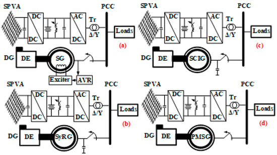
Figure 1.
Off-grid configurations having SPVA and DE driven; (a) SG, (b) SyRG, (c) SCIG, and (d) PMSG.
2.1.2. Off-Grid Configurations Having DG and MHP
The off-grid configurations having DG and MHP, are presented in Figure 2. To reduce the complexity and to avoid the synchronization issues, MHP driven generators can be linked to the DC bus as presented in Figure 2. The configuration shown in Figure 2a ensures supply with constant voltage and frequency in the presence of disturbances as compared to other configurations shown in Figure 2. Because of the installation cost, configurations are given in Figure 2b,c, are suitable, but they require robust control to ensure synchronization with the PCC. Both DESs for configurations presented in Figure 2 are based on electric machines where their stators are connected to the PCC. The nonlinear loads can deteriorate the performance of the generators. However, the interfacing inverter should act as an active filter to keep running the generators at the required performance.
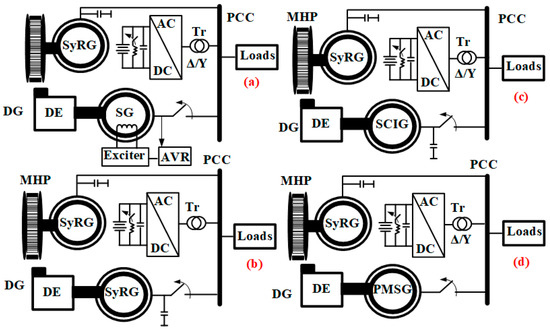
Figure 2.
Off-grid configurations having MHP driven SyRG and DE driven: (a) SG, (b) SyRG, (c) SCIG, and (d) PMSG.
2.1.3. Off-Grid Configurations Having DG and WT
The off-grid configurations having DG and WT, are suitable for places with good wind potential. As presented in Figure 3, DGs and WTs are linked to the AC side and a BES is supported by an interfacing inverter operated as a static compensator (STATCOM) to maintain AC bus voltage and frequency during transitions. The SGs coupled to DEs shown in Figure 3, is replaceable by SyRG, PMSG, or SCIG along with required control. Configurations gave in Figure 3 b,c, are simple and cost-effective according to the detailed study realized in [58,59]. A new techno-economic and environmental analysis for off-grid configuration based on WT and DG are given in [60]. The power quality issues at the PCC can affect both generators when the nonlinear load is connected. However, in the secondary control for the hierarchal coordinate control for the off-grid configurations shown in Figure 3, harmonics mitigation should be considered.
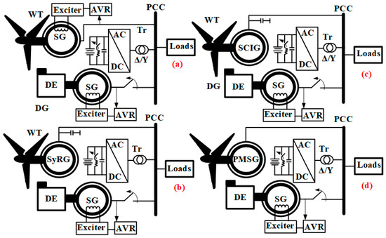
Figure 3.
Off-grid configurations having DE driven SG and WT driven: (a) SG, (b) SyRG, (c) SCIG, and (d) PMSG.
2.2. Off-Grid Configurations Having Three DESs
Owing to the continuous presence of NERs, the reliability can be improved with augmented numbers of DESs. All such off-grid configurations consisting of three DESs, are discussed here.
2.2.1. Configurations Having SPVA, WT, and DG
In Figure 4, off-grid configurations having SPVA, WT, and DG, are presented. The DG, in these configurations, relates to a selector switch, to provide the power to the connected load and BES, simultaneously when connected on the DC side, or to ensure uninterrupted power supply with fixed frequency and voltage when connected to the AC side, even during faults on the DC side or absence of NERs. From the cost and simplicity viewpoint, the configurations are given in Figure 4a,b are considered as good alternatives.
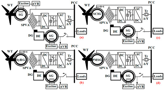
Figure 4.
Off-grid configurations having SPVA, DE driven SG and WT driven: (a) SG, (b) SyRG, (c) SCIG, and (d) PMSG.
2.2.2. Configurations Having WT, MHP, and DG
Off-grid configurations that possess WT, MHP, and DG as DESs given in Figure 5, are targeted to remote places with good wind potential and located close a canal with a risk of the dry season. For this type of application, it is preferable to connect DG to the AC side as shown in Figure 5 to avoid the risk of short or long blackouts during faults. To avoid synchronization problems, all DESs are linked to the DC side using three-phase rectifiers. Off-grid configurations shown in Figure 5c,d, are the good choice for high power applications, and for small power applications, the configurations presented in Figure 5a,b, are preferred. Regarding the performance of these configurations can be analyzed using the same technique developed in [61]. The structure of control for this type of configuration is detailed in [51].
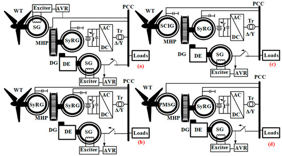
Figure 5.
Off-grid configurations having MHP driven SyRG, DE driven SG and WT driven: (a) SG, (b) SyRG, (c) SCIG, and (d) PMSG.
2.2.3. Configurations Having SPVA, DG, and MHP
The off-grid configurations with SPVA, DG, and MHP are presented in Figure 6. The DG is linked to both sides of the system (AC/DC) via a selector switch to ensure an uninterruptible supply at any time, as well as to charge BES. The configurations presented in Figure 6c,d, are preferred to large power applications. However, for small and medium power applications, configurations presented in Figure 6a,b, are considered as respectable choices.
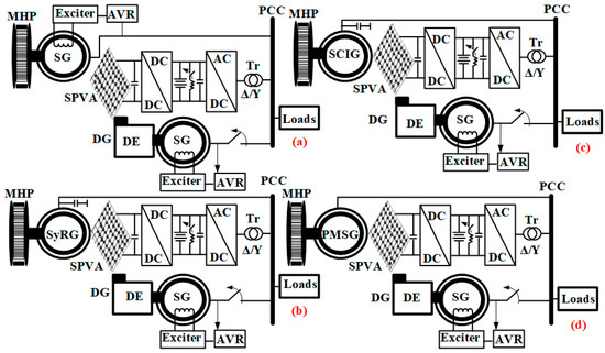
Figure 6.
Off-grid configurations having SPVA, MHP, DE driven SG, and MHP driven: (a) SG, (b) SyRG, (c) SCIG, and (d) PMSG.
2.3. Off-Grid Configurations Having Four DESs
In Figure 7, off-grid configurations that possess SPVA, WT, MHP, and DG, are presented. The DG is used in these configurations as backup DES and connected to both sides of the system (AC/DC). For large power applications, the configurations are given in Figure 7c,d are used. For small and medium power, the configurations presented in Figure 7a,b, are recommended as the best alternatives. Further off-grid configurations having more than four DESs are also considered as per the availability of NERs such as tidal, geothermal, biomass energy sources. The generator and controller are selected based on power potential, cost, and hardware complexity limitations, as well as the decision of the user.
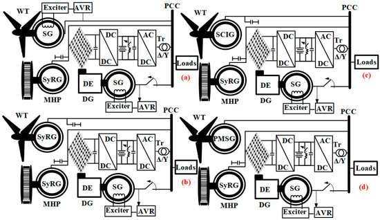
Figure 7.
Off-grid configurations having SPVA, MHP driven SyRG, DE driven SG, and WT driven: (a) SG, (b) SyRG, (c) SCIG, and (d) PMSG.
3. Control Approaches for Off-Grid Systems
For the safe and optimal operation of the off-grid configurations, exclusive hierarchical control, which is subdivided into three levels; (1) primary, (2) secondary, and tertiary control, is used for the selected off-grid configuration. This hierarchical control is structured in the international standard IEC 62264 and ISA-95 for enterprise-control system integration [53,62]. The control of the SPVS, BES, and the dump load, is part of the primary control. The secondary and the tertiary controls are achieved by controlling the interfacing inverter. The secondary control undertakes the restoration of the system frequency and AC voltage deviation, and synchronization between the off-grid system and DG and it ensures the transition between grid-connected mode and an islanding mode. The import of the power from the DG to the DC link to charge the battery is ensured by the tertiary control. The nature of the developed hierarchical control should achieve the following objectives: (1) keep running at peak performance the DG at nonlinear loads when the system operates in the local grid-connected mode (with DG), (2) ensuring to the connected AC loads a stable and constant voltage as well as the constant frequency when the off-grid system operates in the standalone mode (without DG), (3) guaranteeing a soft and secure transition between local-grid and standalone operation modes, and (4) to balance, manage and optimize the power in the system. In this context, the developed hierarchical control for the selected configurations is detailed in the following section.
3.1. Control for Boost Converter of SPVA
As presented in off-grid configurations in the previous section, SPVA is linked to the common DC side via a boost converter to match the output voltage and to achieve MPPT. As already discussed, the P&O technique performs poorly when the system is subjected to rapid sunlight variation. This drawback is solved by reinforcing this method using i.e., the sliding mode control with the boundary layer, as presented in Figure 8. The boost converter output (vout) and input voltages (vpv), as well as, the inductor current (iL), are mandatory to obtain the control (d), which is equal to the sum of equivalent control (deq) and switching control (ds). SPVA current (impv) is calculated using the classical P&O technique.
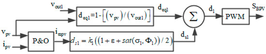
Figure 8.
Enhanced the P&O technique having a sliding mode approach.
3.2. Control for DC Dump Load
As presented in Figure 1, Figure 2, Figure 3, Figure 4, Figure 5, Figure 6 and Figure 7, in off-grid configurations, the DC dump load is linked to the DC bus to absorb the excess power generated from NERs, if BES is fully charged. It can also be replaced by a pump load, smart load. For the last case, the load power demand and the state of the charge of BES (SOC%) should be considered to protect BES from overcharging when it is fully charged. However, a new inner loop is to be integrated with the developed MPPT technique to operate according to load power demand and SOC%.
3.3. Control Approach for DG Selector Switch
The DG in these off-grid configurations is connected to the AC side through controlled switches. Figure 9 presents a model of DG along with a selector switch. This model consists of two parts: (1) mechanical unit with the speed controller, actuator, and DE; (2) electrical unit, which can be either SG or other electric machines as detailed in the previous section. DG is employed as a backup energy source and it runs if the SOC% of BES is less or equal to the selected level e.g., 50% in this case, and the generated power from NERs (PRESs) is smaller than the load power demand (PL) as,
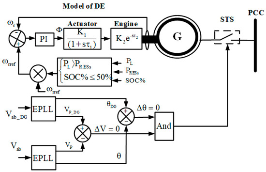
Figure 9.
DG model and its control algorithm based EPLL.
Furthermore, for secure connection of DG to AC side, some additional conditions are to be met, given as, (1) the amplitudes of DG terminal voltage (VPDG) and PCC voltage (Vp) should be equal, and (2) difference between phase angles of the PCC voltage (θ) and DG voltage (θDG) should be zero (Δθ = 0), where, θ and θDG denote the phase angle of the PCC and generator terminal voltages, respectively.
To achieve secure synchronization of DG with the PCC under the presence of perturbation enhanced phased locked loop (EPLL) is suggested. EPLL performs well under disturbance.
3.4. Control for Interfacing Inverter
The three-phase interfacing inverter in these configurations is controlled to realize many purposes, as maintaining constant PCC voltage and frequency, balancing and leveling of loads, and improving the power quality. For the frequency regulation, the interfacing inverter must operate at desired frequency i.e., 50/60 Hz. The proportional resonant (AWPRC) and proportional-integral (AWPI) controllers with anti-windup are suggested for the inner and outer control loops to achieve high-level performance without saturation during the transition. As presented in Figure 10, two levels of the coordinated control algorithm are employed. A selector switch is used for correct control option (d(abc)1 or d(abc)2). However, if the generated power from DESs, which are connected to PCC, is zero (), the selector control (d1(abc)), is obtained as shown in Figure 10.
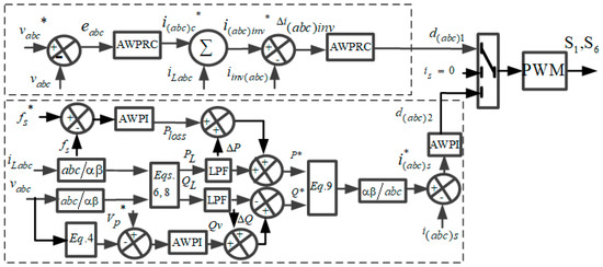
Figure 10.
Control for interfacing inverter.
The PCC phase reference voltages are expressed as,
where Vp denotes the amplitude of the PCC voltages and ωs is the angular frequency, described as,
where fs is the system frequency.
The reference voltages (vabc*) are compared with sensed PCC voltages (vabc), the errors are fed to AWPRC controller, the outputs of outer loops, which represent the output filter currents (iC(abc)*), are added with load currents (iL(abc)). The sum of output filter (iinv(abc)) currents and load currents represent the reference interfacing inverter currents (iinv(abc)*). The obtained currents are compared with the sensed output interfacing inverter currents (iinv(abc)). The errors are fed to AWPRC and the output signals (d1(abc)) are used to get the switching pulses. If (), selector selects the second control (d2(abc)). For this level of control, the value of the PCC voltage amplitude is calculated using (4) to compare it with its reference (Vp*), and the error is fed to the AWPI controller. The output signal represents the reactive power required to maintain the amplitude of the PCC constant (Qv) during the transition. However, Vp is calculated as,
where Vabc denotes the PCC phase voltage.
The reactive load reference power (Q*) is obtained by subtracting the reactive load power (QL) from (Qv) as,
where the QL is calculated as,
where Vα, Vβ, iLα, and iLβ denote the PCC voltages and load currents in α-β transformation.
To import or export reactive power from PCC, the variation of reactive power (ΔQ) is added with Qv.
The reference active load power (P*) is calculated by adding the active power loss (Ploss) with PL as,
The active load power (PL) is calculated as,
To import or export active power from PCC, the variation of active power (ΔP) is added with Ploss.
The reference source currents in α-β are estimated as,
Using inverse Clark’s transformation, the estimated reference source currents (isα*, isβ*), are transformed into three-phase currents (isa*, isb*, and isc*), and compared with the sensed currents of DESs, which are connected to the PCC. The errors of currents are fed to AWPI and the output signals are used to obtain the gating pulses for interfacing inverter.
3.5. Control for BES
The BES is taken as a common component in these off-grid configurations of Figure 1, Figure 2, Figure 3, Figure 4, Figure 5, Figure 6 and Figure 7. This component can be linked to the common DC bus directly as well as through the DC-DC buck-boost converter. Additional equipment such as a battery management system is required to protect BES from operating outside its safe operating area, monitoring SOC%, calculating BES data, reporting that data, and controlling its environment [63].
4. Results and Discussion
To test the performance of the developed control strategies demonstrated in Figure 1, Figure 2, Figure 3, Figure 4, Figure 5, Figure 6 and Figure 7, two off-grid configurations are selected. Many scenarios in the presence of nonlinear loads and weather conditions changes are tested using MATLAB/Simulink and implemented in real-time using a hardware prototype.
Figure 11 shows the prototype to validate the selected off-grid configurations and their control strategies. It consists of (1) emulator of the wind turbine, and (2) emulator of DG, (3) synchronizer, (4) lead-acid batteries, (5) loads, (6) inverters, (7) dSPACE, (8) PV emulator, (9) sensors, and (10) a transformer.
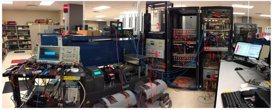
Figure 11.
Hardware prototype.
4.1. Performance of Off-Grid Configuration Based on SPVA, DG, and WT
Figure 12 shows the selected off-grid configuration based on SPVA, WT, and DG. The WT coupled with SCIG and DE coupled with SG are connected directly to the PCC, and the SPVA is connected to the PCC through DC-DC boost converter and DC/AC interfacing inverter. The BES and dump load are connected to the common DC bus. The operation modes for the selected configuration are detailed in Table 1.
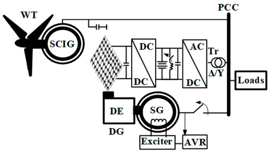
Figure 12.
Off-grid configuration based on SPVA, WT, and DG.

Table 1.
Operation modes for off-grid configuration based on SPVA, DG, and WT.
The dynamic performance of the selected off-grid configuration shown in Figure 12 when operates in modes 1, 2, and 4 is shown in Figure 13. The system is subjected to a sudden decrease in the wind speed at t = 0.8 s. The solar irradiation is kept constant and the SOC of BES is greater than 50%. The objective of this test shows the performance of the hierarchical control tasks, such as voltage and frequency regulation and power quality improvement at PCC, as well as the extraction of MPPT from SPVA. Seeing that WT is connected to the PCC, is ≠ 0, where is = (iDG + iWT), the second level of control selected. One observes in Figure 13a that the AC voltage (vL) and system frequency (fs) are well regulated, and the reference output PV current (ipv) follows its reference (impv).
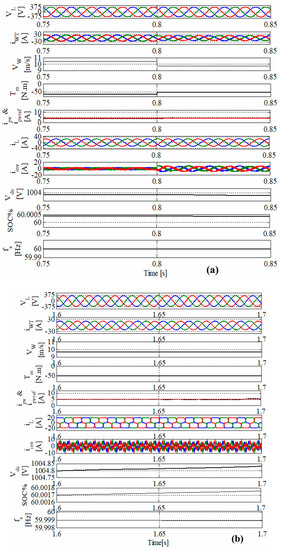
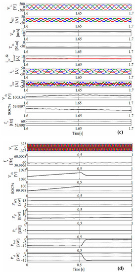
Figure 13.
Dynamic performance off-grid configuration based on SPVA, WT, and DG under (a) variation of wind speed with greater than 50%, (b) balanced nonlinear load, (c) unbalanced nonlinear load, and (d) when SOC% equal to 100%.
At t = 0.8 s, the system is subjected to a sudden decrease in the wind speed that is why the output inverter current (iinv) is increasing. This is because BES helps to balance the power in the system by providing the difference of power to the connected loads. One can see clearly that the AC voltage and system frequency are kept constant without any deviation, which confirms the robustness of the proposed control strategy based on AWPI controller for voltage and frequency regulation.
The performances at balanced and balanced nonlinear loads are demonstrated in Figure 13b,c. Seeing that the stator windings of SCIG in the short-capacity system are to be greatly influenced by harmonics generated by nonlinear loads. This causes an oscillatory electromagnetic torque and brings mechanical vibration in the generator shaft. To avoid this scenario and keep running with the optimal performance of the SCIG, the harmonics should be mitigated. One observes, even balanced nonlinear loads and unbalanced nonlinear loads are connected to the PCC, the stator currents of SCIG (iWT) are sinusoidal and balanced, which confirms that tasks related to the power quality improvement at the PCC are achieved and the generators operate safely with their optimal performance.
The performance of off-grid configuration when operates at mode 4 is presented in Figure 13d. The objective of this test to validate the control of the dump load when the BES is fully charged and the generated power from WT and SPVA are higher than consumed load power. One sees clearly at t = 0.5 s, the SOC reaches its limit and becomes equal to 100%. To balance the power in the system and to protect the BES from overcharging, a dump load is turned on to dissipate the excess of generated power in resistors. This confirms that off-grid configuration operates well and with optimal performance under different conditions.
Figure 14 shows experimental waveforms of the off-grid configuration shown in Figure 12 when the system operates in modes 1 and 2, where SOC of the BES is greater than 50% and the solar irradiation suddenly decreases at t = 0.2 s. It results in a change in the voltage and the current of SPVA and the BES current. It shows the charging/discharging of BES by an increase/decrease in the BES current. It is observed that the PCC voltage remains constant at these variations, which confirms the robustness of MPPT, frequency, and voltage control.
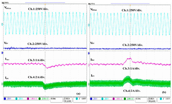
Figure 14.
Performance of WT-SPVA based off-grid system with (a) decrease in solar irradiation, and (b) increase in solar irradiation.
4.2. Performance of Off-Grid Configuration Based on SPVA and DG
Figure 15 shows the selected off-grid configuration based on SPVA and DG. The SPVA is connected to the PCC through a DC-DC boost converter and a DC/AC interfacing inverter. The BES and dump load are connected directly to the common DC bus. The operation modes of the selected off-grid configuration are detailed in Table 2.
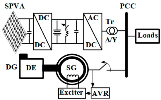
Figure 15.
Off grid-configuration based on SPVA and DG.
Table 2.
Operation modes for off-grid configuration based on SPVA and DG.
The performance of the PCC voltages (vL), stator currents of SG (iDG)m load currents (iL), output inverter current (iinv), SPVA current (ipv) and its reference current (ipvref), DC link voltage (Vdc), SOC of the BES and the system frequency (fs), are demonstrated in Figure 16a. The objective of this test is to validate the performance of the MPPT, frequency, and voltage regulation at the PCC and the behavior of the AWPRC controllers during transitions. This test is conducted using a dynamic linear load and under solar irradiation. One observes that the SOC% is 50% ≤ SOC% ≤ 100% and ipv < iL that is why the BES is discharging. Based on these conditions, off-grid configuration operates in mode 2, for this reason, the DG is turned off (iDG = 0). One observes that the PCC voltage and the system frequency are regulated and the SPVA current follows it a reference, which is estimated using the enhanced P&O technique detailed in Figure 8. One sees under sudden decreasing of the SPVA current and increasing of load current, the voltage and frequency are maintained constant, which confirms that the AWPRC controllers perform well under steady-state and dynamic operations without any saturation issue. In this operating mode as well as in modes 2 and 4, DG loads are supplied from SPVA and BES, which allows to reduce significantly the excessive use of fossil fuel, as well as to increase the DG lifespan.
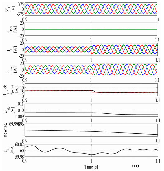
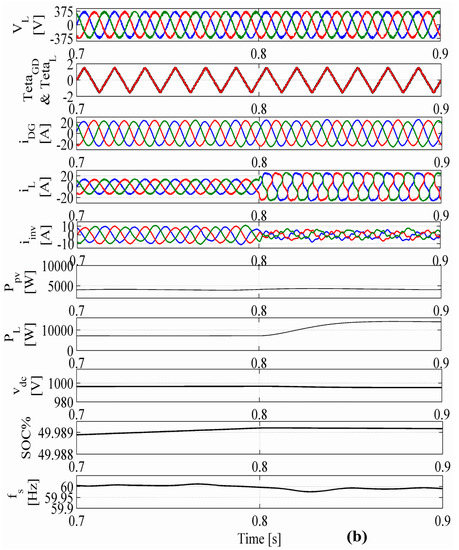
Figure 16.
The dynamic performance of the PV-DG based off-grid configuration under loads and solar irradiation change with (a) SOC of BES greater than 50%, and (b) less than 50%.
The performances when the off-grid configuration operates in mode 3 are presented in Figure 16b. The objective of this test is to show the capability of the second level of the interfacing inverter control to mitigate harmonics created by the sudden connection of the nonlinear load at t = 0.8 s, as well as to balance the source current. As already indicated in the motivation that DG as well as all connected DESs such as WT and MHP for off-grid configurations shown in Figure 1, Figure 2, Figure 3, Figure 4, Figure 5, Figure 6 and Figure 7 should keep running at optimal performance at nonlinear loads. One observes clearly that at t = 0.8 s, the load becomes nonlinear. To protect DG and to enhance its performance in this operation mode, an interfacing inverter acts as an active filter. As is detailed in Table 2, to operate in mode 3, the conditions as, PL > PPV and SOC% ≤ 50% should be satisfied. Moreover, to connect DG to the PCC by switching on the STS, the phase’s shift of the stator terminals and that of PCC as well as the AC-voltage amplitude on both sides should be equal. One observes that all these conditions are satisfied. The obtained performance confirms that the selected enhanced locked loop performs well for these tests to achieve the desired tasks in the presence of disturbance and noise. Furthermore, to maintain constant and sinusoidal the AC voltage at the PCC, as well as, regulated frequency during transitions and in presence of nonlinear load, confirms the robustness of the second level of control and its AWPI controllers under the presence of severs conditions.
The real-time performances of the off-grid configuration shown in Figure 15, are demonstrated in Figure 17. The waveforms of the stator voltage of the phase “a” before (vDGa1) and after a transformer (vDGa1), excitation current (iexc), and stator current of phase “a” (iDGa), are shown in Figure 16a,b. Performances of the stator voltage of the phase “a” before (vDGa1) and after a transformer (vDGa1), as well as the stator current of phase “a” (iDGa) and “b” (iDGb), are shown. The objective of this test is to validate the steady-state performance of the second level of the control under the presence of linear load when off-grid configuration operates in mode 3. One observes that the system performs well, and the PCC voltage and the frequency are well regulated.
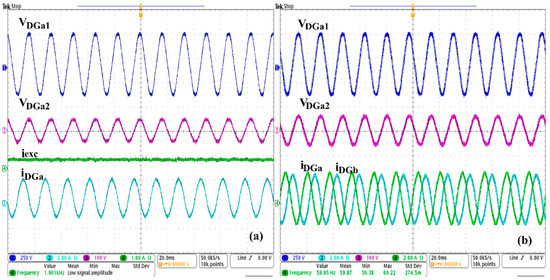
Figure 17.
Experimental results under the presence of linear load at (a) excitation circuit and, (b) PCC.
The real-time performances during steady-state and dynamic operations are shown in Figure 18. In Figure 18a, the performances after synchronization of the DG with PCC of the stator voltages before the transformer (vDGa, vDGb, and vDGc), as well as the excitation current are shown. The performances of PCC (vDGa) and stator voltages (vLa) of phase “a”, and DG (iDGa) and the load current (iLa) are shown in Figure 18b. One observes in Figure 18b, that at t = 0.8 ms, conditions to synchronize DG with PCC are satisfied. At this time, conditions (Δθ = 0 and ΔV = 0) as demonstrated in Figure 9 are fulfilled, which allows the STS to switch on. One observes that transition is hard, but the voltage and frequency are kept constant, which confirms the robustness of the proposed control to achieve a transition to mode 3 without any saturation issue of the AWPI controllers and in the presence of noise.
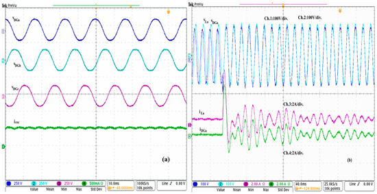
Figure 18.
Experimental results of DG: (a) steady-state, and (b) during synchronization with PCC.
The real-time performance at PCC of the first level of control (without DG) is shown in Figure 19. The dynamic performances under sudden increasing and decreasing of linear load at t = 96 ms and t = 264 ms, respectively are shown in Figure 19 a,b. Performances at PCC under the sudden switch off and on phase “a” at t = 64 ms and t = 208 ms, respectively are presented in Figure 19b. The objective of these tests is to validate the performance of the first level of control, which is based on the PRC controller with anti-windup feedback. One observes clearly that during the sudden increase and decrease of loads, as well as during switching on and off of one load phase, PCC voltage and frequency are well regulated without any saturation issue, which confirms the robustness of the proposed control for this operation of modes (without DG).
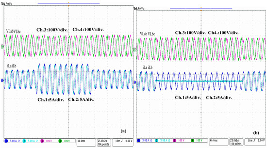
Figure 19.
Test results of AWPRC for PCC voltage regulation under (a) sudden load variation, and (b) unbalanced linear load.
The real-time performance under load variation at the DC side is shown in Figure 20. Performance under the sudden increase of linear load at t = 400 ms and sudden decreasing at t = 1.6 s of DC link voltage (Vdc), BES current (ibat), load current (iLa), and output inverter current of phase “a” are shown in Figure 20a, and the performances under decreasing of load at t = 300 ms and switched off of the phase a at t = 800 ms are shown in Figure 20b. One observes that charge and discharge of BES to balance the power in the system vary with the variation of the loads and the available power, which has provided from SPVA. This confirms the importance of the BES in this type of installation to maintain the system operation stable, ensuring an uninterruptible supply to the connected loads and compensating the intermittency of the SPVA.
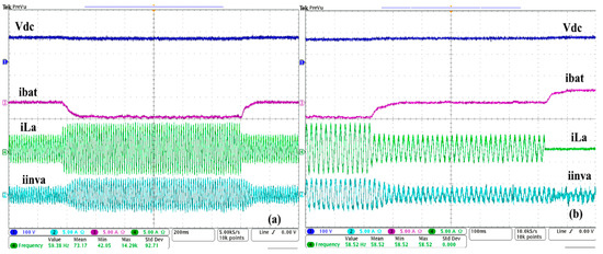
Figure 20.
Experimental results under fixed solar irradiation and load change when SOC% of BES is greater than 50%: (a) increasing and decreasing of linear load, (b) decreasing of nonlinear load, and switched off the phase ‘a’.
Performances at the PCC under the presence of connecting and disconnecting the nonlinear loads are shown in Figure 21. The output inverter current (iinva), load current (iLa), DG current (iDGa), and DC link voltage (Vdc) under the presence of nonlinear type RL, are presented in Figure 21a, and real-time performances under the presence of nonlinear type RC, are presented in Figure 21b. The performances under sudden increasing and decreasing of nonlinear type RL are presented in Figure 18c. The objectives of this test are to validate the proposed technique to improve the power quality at the PCC in the presence of nonlinear loads. One observes from these test results that the interfacing inverter acts as an active filter. It compensates harmonics and balances the DG currents. Moreover, the AWPI controllers perform well under sudden variation of loads without any saturation issue, which confirms the robustness of the developed control strategies for operating mode 3. This is proving that DG can operate in the presence of severe conditions with optimal performance.
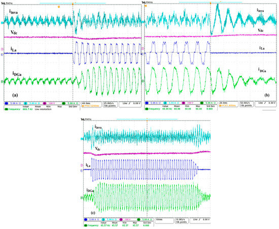
Figure 21.
Experimental results during the presence of (a,b) balanced nonlinear load, and (c) sudden connected and disconnected of the load.
5. Potential Applications
The applications of these off-grid systems in remote areas or hilly regions include home and street lighting, water pumping and domestic appliances, water purifier plants, wastewater treatment, and disposal system, cattle, and chicken farming centers, dairies, tourist cottage and resorts, aerial ropeway transport system, restaurants, telecom towers and exchanges, petroleum refilling stations, health care facilities, community centers, kindergarten, old-age homes, cold storage, mine sites, and military bases. A specific application as an electric vehicle charging station may be of potential interest in the future.
6. Conclusions
A comprehensive study of many off-grid configurations and their coordinated control for renewable energy sources integration have been presented in this work for sustainable and uninterrupted power supply to rural and isolated areas. These off-grid configurations are classified into 28 configurations based on energy sources and their control, generators, and load requirements. Performance simulation and its validation on prototypes are presented to verify the application of the off-grid system under variable weather conditions. The obtained simulation and experimental results show satisfactory performance at linear and nonlinear loads. Where DG is kept running at optimal performance at nonlinear loads. It has been shown that loads are powered continuously with constant voltage and frequency, and transition between different operating modes (with/without DG). It has been realized safely without any divergence of controllers in the presence of disturbance and noise, which confirms the robustness of EPLL and the proposed controllers with anti-windup feedback and their optimal gains design. This work is expected to serve as a reference to researchers and practicing engineers for the design, operation, and control of new combinations of renewable energy sources integrated into the off-grid system.
Author Contributions
This paper was a collaborative effort between the authors. M.R. contributed to the design of the control, simulations, experiments, and drafted the manuscript. S.S. and H.I. performed in the design of system elements, experiments and revision of the manuscript. A.C. and B.S. supervised the work, provided advice on methodology and results. All authors have read and agreed to the published version of the manuscript.
Funding
This research received no external funding.
Conflicts of Interest
The authors declare no conflict of interest.
Abbreviations
| DERs | Distributed energy resources |
| NERS | Natural energy resources |
| DGs | Diesel generators |
| DESs | Distributed Energy sources |
| BES | Battery energy storage |
| SPVA | Solar photovoltaic arrays |
| DC | Direct current |
| AC | Alternative current |
| PCC | Point of common coupling |
| WT | Wind turbine |
| MHP | Micro-hydropower |
| MPPT | Maximum power point tracking |
| P&O | Perturb and observe technique |
| V/f | Control voltage/frequency |
| SyRG | Synchronous reluctance generator |
| PMSG | Permanent magnet synchronous generator |
| SG | Synchronous generator |
| SCIG | Squirrel cage induction generator |
| DEs | Diesel engines |
| AVR | Automatic voltage regulator |
| STATCOM | Static compensator |
| vout | Boost converter output voltage, V |
| vpv | Boost converter input voltage, V |
| iL | Inductor current, A |
| d | Control signal |
| deq | Equivalent control signal |
| impv | Reference maximum current, A |
| SOC% | State of charge of battery |
| PL | Load power demand, W |
| PRESs | Generated power from renewable energy sources, W |
| VPDG | Amplitudes of DG terminal voltage, V |
| Vp | Amplitudes of PCC voltage, V |
| θ | Phase angles of the PCC voltage, rad |
| θDG | Phase angles of DG voltage, rad |
| EPLL | Enhanced phased locked loop |
| AWPRC | Proportional resonant with anti-windup feedback |
| AWPI | Proportional integral with anti-windup feedback |
| d1(abc) | Control signals generated by the first level of coordinated control |
| d2(abc) | Control signal generated by the second level of coordinated control |
| PWT | Generated power from wind turbine, W |
| PDG | Generated power from diesel generator, W |
| PMHP | Generated power from micro-hydropower, W |
| fs | System frequency, Hz |
| Vabc* | PCC reference voltages, V |
| Vabc | Sensed PCC voltages, V |
| ic(abc)* | Reference RC output filter current, A |
| iL(abc) | Sensed load current, A |
| iinv(abc) | Sensed output inverter currents, A |
| Q* | Reactive load reference power, Var |
| QL | Reactive load power, Var |
| Vα, Vβ | PCC voltage in -β transformation |
| iLα, iLβ | Load currents in -β transformation |
| P* | Reference active load power, W |
| Ploss | Active power loss, W |
| PL | Active load power, W |
| Pbat | Battery power, W |
| isα*, isβ* | Estimated source currents reference in α-β transformation |
| isa*, isb*, and isc* | Estimated source currents in the natural reference frame |
| iexc | Excitation current in the synchronous generator, A |
References
- The true Cost of Providing Energy to Telecom Towers in India. Available online: https://telecom.economictimes.indiatimes.com (accessed on 1 May 2020).
- The First Canadian Smart Remote Microgrid. Available online: https://www.nrcan.gc.ca (accessed on 1 May 2020).
- Peña, R.; Cárdenas, R.; Proboste, J.; Clare, J.; Asher, G. Wind–Diesel Generation Using Doubly Fed Induction Machines. IEEE Trans. Energy Convers. 2008, 23, 202–214. [Google Scholar] [CrossRef]
- Gan, L.K.; Shek, J.K.; Mueller, M.A. Hybrid wind–photovoltaic–diesel–battery system sizing tool development using empirical approach, life-cycle cost and performance analysis: A case study in Scotland. Energy Convers. Manag. 2015, 106, 479–494. [Google Scholar] [CrossRef]
- Yamegueu, D.; Azoumah, Y.; Py, X. Experimental and economical study of sustainable electricity generation by solar PV/diesel hybrid systems without storage for off grid areas. Energy Sustain. III 2011, 143, 37–49. [Google Scholar] [CrossRef]
- Giannoutsos, S.V.; Manias, S.N. Development of an integrated energy efficiency control system for ship power balance and diesel generator fuel consumption optimization. In Proceedings of the 2013 IEEE Industry Applications Society Annual Meeting, Lake Buena Vista, FL, USA, 6–11 October 2013; pp. 1–11. [Google Scholar]
- Bhandari, Y.; Chalise, S.; Sternhagen, J.; Tonkoski, R. Reducing fuel consumption in microgrids using PV, batteries, and generator cycling. In Proceedings of the IEEE International Conference on Electro-Information Technology, EIT 2013, Rapid City, SD, USA, 9–11 May 2013; pp. 1–4. [Google Scholar]
- Gharibi, M.; Askarzadeh, A. Technical and economical bi-objective design of a grid-connected photovoltaic/diesel generator/fuel cell energy system. Sustain. Cities Soc. 2019, 50, 101575. [Google Scholar] [CrossRef]
- Arkhangelski, J.; Siano, P.; Mahamadou, A.-T.; Lefebvre, G. Evaluating the Economic Benefits of a Smart-Community Microgrid with Centralized Electrical Storage and Photovoltaic Systems. Energies 2020, 13, 1764. [Google Scholar] [CrossRef]
- Cecilia, A.; Carroquino, J.; Roda, V.; Costa-Castelló, R.; Barreras, F. Optimal Energy Management in a Standalone Microgrid, with Photovoltaic Generation, Short-Term Storage, and Hydrogen Production. Energies 2020, 13, 1454. [Google Scholar] [CrossRef]
- Thankappan, A.T.; Simon, S.P.; Nayak, P.S.R.; Sundareswaran, K.; Padhy, N. Pico-hydel hybrid power generation system with an open well energy storage. IET Gener. Transm. Distrib. 2017, 11, 740–749. [Google Scholar] [CrossRef]
- Benhalima, S.; Miloud, R.; Chandra, A. Real-Time Implementation of Robust Control Strategies Based on Sliding Mode Control for Standalone Microgrids Supplying Non-Linear Loads. Energies 2018, 11, 2590. [Google Scholar] [CrossRef]
- Zhu, Y.; Wang, Z.; Liu, Y.; Wang, H.; Tai, N.; Jiang, X. Optimal Control of Microgrid Operation Based on Fuzzy Sliding Mode Droop Control. Energies 2019, 12, 3600. [Google Scholar] [CrossRef]
- Yan, X.; Cui, Y.; Cui, S. Control Method of Parallel Inverters with Self-Synchronizing Characteristics in Distributed Microgrid. Energies 2019, 12, 3871. [Google Scholar] [CrossRef]
- Toub, M.; Bijaieh, M.M.; Weaver, W.W.; Iii, R.D.R.; Maaroufi, M.; Aniba, G.; Robinett, R.D. Droop Control in DQ Coordinates for Fixed Frequency Inverter-Based AC Microgrids. Electronics 2019, 8, 1168. [Google Scholar] [CrossRef]
- Nguyen, T.-T.; Yoo, H.-J.; Bui, V.-H. A Droop Frequency Control for Maintaining Different Frequency Qualities in a Stand-Alone Multimicrogrid System. IEEE Trans. Sustain. Energy 2018, 9, 599–609. [Google Scholar] [CrossRef]
- Li, D.; Zhao, B.; Wu, Z.; Zhang, X.; Zhang, L. An Improved Droop Control Strategy for Low-Voltage Microgrids Based on Distributed Secondary Power Optimization Control. Energies 2017, 10, 1347. [Google Scholar] [CrossRef]
- Lyu, Z.; Yang, X.; Zhang, Y.; Zhao, J. Bi-Level Optimal Strategy of Islanded Multi-Microgrid Systems Based on Optimal Power Flow and Consensus Algorithm. Energies 2020, 13, 1537. [Google Scholar] [CrossRef]
- Zhao, Z.; Zhang, J.; He, Y.; Zhang, Y.; Liu, M. Island DC Microgrid Hierarchical Coordinated Multi-Mode Control Strategy. Energies 2019, 12, 3012. [Google Scholar] [CrossRef]
- Yuan, C.; Haj-Ahmed, M.A.; Illindala, M.S. Protection Strategies for Medium Voltage Direct Current Microgrid at a Remote Area Mine Site. IEEE Trans. Ind. Appl. 2015, 51, 1. [Google Scholar] [CrossRef]
- Hatziargyriou, N. Microgrids: Architectures and Control; John Wiley & Sons: Hoboken, NJ, USA, 2014. [Google Scholar]
- Yao, L.; Hou, X.; Wang, X.; Lin, C.; Guerrero, J.M. A Coordinated Control for Photovoltaic Generators and Energy Storages in Low-Voltage AC/DC Hybrid Microgrids under Islanded Mode. Energies 2016, 9, 651. [Google Scholar] [CrossRef]
- Worku, M.Y.; Hassan, M.A.M.; Abido, M.A. Real Time Energy Management and Control of Renewable Energy based Microgrid in Grid Connected and Island Modes. Energies 2019, 12, 276. [Google Scholar] [CrossRef]
- Kumar, D.; Zare, F.; Ghosh, A. DC Microgrid Technology: System Architectures, AC Grid Interfaces, Grounding Schemes, Power Quality, Communication Networks, Applications, and Standardizations Aspects. IEEE Access 2017, 5, 12230–12256. [Google Scholar] [CrossRef]
- Xia, Y.; Peng, Y.; Yang, P.; Yu, M.; Wei, W. Distributed Coordination Control for Multiple Bidirectional Power Converters in a Hybrid AC/DC Microgrid. IEEE Trans. Power Electron. 2017, 32, 4949–4959. [Google Scholar] [CrossRef]
- Shahparasti, M.; Mohamadian, M.; Teimourzadeh-Baboli, P.; Yazdianp, A. Toward Power Quality Management in Hybrid AC-DC Microgrid Using LTC-L Utility Interactive Inverter: Load Voltage-Grid Current Tradeoff. IEEE Trans. Smart Grid 2015, 8, 1–11. [Google Scholar] [CrossRef]
- Battistelli, C.; Agalgaonkar, Y.; Pal, B.C. Probabilistic Dispatch of Remote Hybrid Microgrids Including Battery Storage and Load Management. IEEE Trans. Smart Grid 2017, 8, 1305–1317. [Google Scholar] [CrossRef]
- Loh, P.C.; Li, D.; Chai, Y.K.; Blaabjerg, F. Autonomous Operation of Hybrid Microgrid With AC and DC Subgrids. IEEE Trans. Power Electron. 2012, 28, 2214–2223. [Google Scholar] [CrossRef]
- Lu, X.; Guerrero, J.M.; Sun, K.; Vasquez, J.C.; Teodorescu, R.; Huang, L. Hierarchical Control of Parallel AC-DC Converter Interfaces for Hybrid Microgrids. IEEE Trans. Smart Grid 2013, 5, 683–692. [Google Scholar] [CrossRef]
- Nejabatkhah, F.; Li, Y. Overview of Power Management Strategies of Hybrid AC/DC Microgrid. IEEE Trans. Power Electron. 2014, 30, 7072–7089. [Google Scholar] [CrossRef]
- Thale, S.; Wandhare, R.G.; Agarwal, V. A Novel Reconfigurable Microgrid Architecture With Renewable Energy Sources and Storage. IEEE Trans. Ind. Appl. 2014, 51, 1805–1816. [Google Scholar] [CrossRef]
- Beykverdi, M.; Jalilvand, A.; Ehsan, M. Cooperative Energy Management of Hybrid DC Renewable Grid Using Decentralized Control Strategies. Energies 2016, 9, 859. [Google Scholar] [CrossRef]
- Liu, Y.; Li, Y.; Liang, H.; He, J.; Cui, H. Energy Routing Control Strategy for Integrated Microgrids Including Photovoltaic, Battery-Energy Storage and Electric Vehicles. Energies 2019, 12, 302. [Google Scholar] [CrossRef]
- Chen, M.; Ma, S.; Wan, H.; Wu, J.; Jiang, Y. Distributed Control Strategy for DC Microgrids of Photovoltaic Energy Storage Systems in Off-Grid Operation. Energies 2018, 11, 2637. [Google Scholar] [CrossRef]
- Subudhi, B.; Pradhan, R. A Comparative Study on Maximum Power Point Tracking Techniques for Photovoltaic Power Systems. IEEE Trans. Sustain. Energy 2012, 4, 89–98. [Google Scholar] [CrossRef]
- Chen, P.-C.; Chen, P.-Y.; Liu, Y.-H.; Chen, J.-H.; Luo, Y.-F. A comparative study on maximum power point tracking techniques for photovoltaic generation systems operating under fast changing environments. Sol. Energy 2015, 119, 261–276. [Google Scholar] [CrossRef]
- Ahmed, J.; Salam, Z. A Modified P&O Maximum Power Point Tracking Method With Reduced Steady-State Oscillation and Improved Tracking Efficiency. IEEE Trans. Sustain. Energy 2016, 7, 1506–1515. [Google Scholar] [CrossRef]
- Rezkallah, M.; Hamadi, A.; Chandra, A.; Singh, B.P.; Hamadi, A. Design and Implementation of Active Power Control With Improved P&O Method for Wind-PV-Battery-Based Standalone Generation System. IEEE Trans. Ind. Electron. 2017, 65, 5590–5600. [Google Scholar] [CrossRef]
- Zhao, H.; Hong, M.; Lin, W.; Loparo, K.A. Voltage and Frequency Regulation of Microgrid With Battery Energy Storage Systems. IEEE Trans. Smart Grid 2017, 10, 414–424. [Google Scholar] [CrossRef]
- Peyghami-Akhuleh, S.; Mokhtari, H.; Loh, P.C.; Davari, P.; Blaabjerg, F. Distributed Primary and Secondary Power Sharing in a Droop-Controlled LVDC Microgrid With Merged AC and DC Characteristics. IEEE Trans. Smart Grid. 2018, 9, 2284–2294. [Google Scholar] [CrossRef]
- Scherer, L.G.; De Camargo, R.F.; Tambara, R.V. Voltage and frequency regulation of standalone self-excited induction generator for micro-hydro power generation using discrete-time adaptive control. IET Renew. Power Gener. 2016, 10, 531–540. [Google Scholar] [CrossRef]
- Yoshida, Y.; Farzaneh, H. Optimal Design of a Stand-Alone Residential Hybrid Microgrid System for Enhancing Renewable Energy Deployment in Japan. Energies 2020, 13, 1737. [Google Scholar] [CrossRef]
- Petersen, L.; Iov, F.; Tarnowski, G.C. A Model-Based Design Approach for Stability Assessment, Control Tuning and Verification in Off-Grid Hybrid Power Plants. Energies 2019, 13, 49. [Google Scholar] [CrossRef]
- Yu, Z.; Ai, Q.; He, X.; Piao, L. Adaptive Droop Control for Microgrids Based on the Synergetic Control of Multi-Agent Systems. Energies 2016, 9, 1057. [Google Scholar] [CrossRef]
- Zhang, J.; Li, K.J.; Wang, M.; Lee, W.J.; Gao, H.; Zhang, C.; Li, K. A bi-level program for the planning of an islanded microgrid including CAES. IEEE Trans. Ind. Appl. 2016, 52, 2768–2777. [Google Scholar] [CrossRef]
- Mayet, C.; Pouget, J.; Bouscayrol, A.; Lhomme, W. Influence of an Energy Storage System on the Energy Consumption of a Diesel-Electric Locomotive. IEEE Trans. Veh. Technol. 2013, 63, 1032–1040. [Google Scholar] [CrossRef]
- Kusakana, K. Optimal scheduled power flow for distributed photovoltaic/wind/diesel generators with battery storage system. IET Renew. Power Gener. 2015, 9, 916–924. [Google Scholar] [CrossRef]
- Zhang, L.; Chen, K.; Lyu, L.; Cai, G. Research on the Operation Control Strategy of a Low-Voltage Direct Current Microgrid Based on a Disturbance Observer and Neural Network Adaptive Control Algorithm. Energies 2019, 12, 1162. [Google Scholar] [CrossRef]
- Rezkallah, M.; Chandra, A.; Singh, B.P.; Singh, S. Microgrid: Configurations, Control and Applications. IEEE Trans. Smart Grid 2017, 10, 1290–1302. [Google Scholar] [CrossRef]
- STD; IEEE. IEEE guide for design, operation, and integration of distributed resource island systems with electric power systems. IEEE STD 2011, 1547, 1–54. [Google Scholar]
- Bidram, A.; Davoudi, A. Hierarchical Structure of Microgrids Control System. IEEE Trans. Smart Grid 2012, 3, 1963–1976. [Google Scholar] [CrossRef]
- Palizban, O.; Kauhaniemi, K.; Guerrero, J.M. Microgrids in active network management—Part I: Hierarchical control, energy storage, virtual power plants, and market participation. Renew. Sustain. Energy Rev. 2014, 36, 428–439. [Google Scholar] [CrossRef]
- Shafiee, Q.; Dragicevic, T.; Vasquez, J.C.; Guerrero, J.M. Hierarchical Control for Multiple DC-Microgrids Clusters. IEEE Trans. Energy Convers. 2014, 29, 922–933. [Google Scholar] [CrossRef]
- Aziz, A.S.; Tajuddin, M.F.N.; Adzman, M.R.; Ramli, M.A.M.; Mekhilef, S. Energy Management and Optimization of a PV/Diesel/Battery Hybrid Energy System Using a Combined Dispatch Strategy. Sustainability 2019, 11, 683. [Google Scholar] [CrossRef]
- Singh, B.; Chandra, A.; Al-Haddad, K. Power Quality: Problems and Mitigation Techniques; John Wiley & Sons: Hoboken, NJ, USA, 2014. [Google Scholar]
- IEEE Standard for the Testing of Microgrid Controllers, IEEE Std 2030.8TM-2018. Available online: https://ieeexplore.ieee (accessed on 31 December 2018).
- Acevedo, L.; Uche, J.; Del Almo, A.; Círez, F.; Usón, S.; Martínez, A.; Guedea, I. Dynamic Simulation of a Trigeneration Scheme for Domestic Purposes Based on Hybrid Techniques. Energies 2016, 9, 1013. [Google Scholar] [CrossRef]
- Wu, T.; Yu, W.; Wang, L.; Guo, L.; Tang, Z. Power Distribution Strategy of Microgrid Hybrid Energy Storage System Based on Improved Hierarchical Control. Energies 2019, 12, 3498. [Google Scholar] [CrossRef]
- Uche, J.; Acevedo, L.; Círez, F.; Usón, S.; Martínez-Gracia, A.; Bayod-Rújula, Á.A. Analysis of a domestic trigeneration scheme with hybrid renewable energy sources and desalting techniques. J. Clean. Prod. 2019, 212, 1409–1422. [Google Scholar] [CrossRef]
- Salisu, S.; Mustafa, M.W.; Olatomiwa, L.; Mohammed, O.O. Assessment of technical and economic feasibility for a hybrid PV-wind-diesel-battery energy system in a remote community of north central Nigeria. Alex. Eng. J. 2019, 58, 1103–1118. [Google Scholar] [CrossRef]
- Ngan, M.S.; Tan, C.W. Assessment of economic viability for PV/wind/diesel hybrid energy system in southern Peninsular Malaysia. Renew. Sustain. Energy Rev. 2012, 16, 634–647. [Google Scholar] [CrossRef]
- International Society of Automation. Enterprise-Control System Integration IEC62264-1:2013. Available online: https://www.isa.org/standards (accessed on 1 May 2020).
- Gontijo, G.; Soares, M.; Tricarico, T.; Dias, R.; Aredes, M.; Guerrero, J.M. Direct Matrix Converter Topologies with Model Predictive Current Control Applied as Power Interfaces in AC, DC, and Hybrid Microgrids in Islanded and Grid-Connected Modes. Energies 2019, 12, 3302. [Google Scholar] [CrossRef]


© 2020 by the authors. Licensee MDPI, Basel, Switzerland. This article is an open access article distributed under the terms and conditions of the Creative Commons Attribution (CC BY) license (http://creativecommons.org/licenses/by/4.0/).