The Impact of Heat Exchangers’ Constructions on the Melting and Solidification Time of Phase Change Materials


Abstract
1. Introduction
2. Basics of Heat Transfer in LHTES
2.1. The Influence of HTF Inlet Parameters
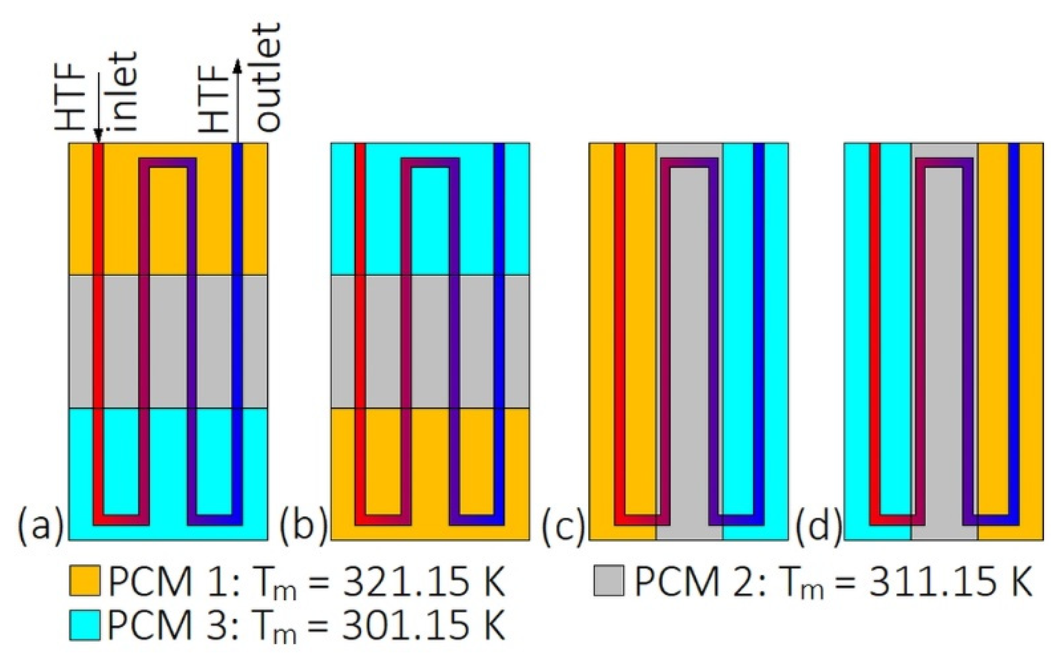
2.2. The Application of Multiple PCMs
3. Types of Heat Exchangers Used in LHTES Systems
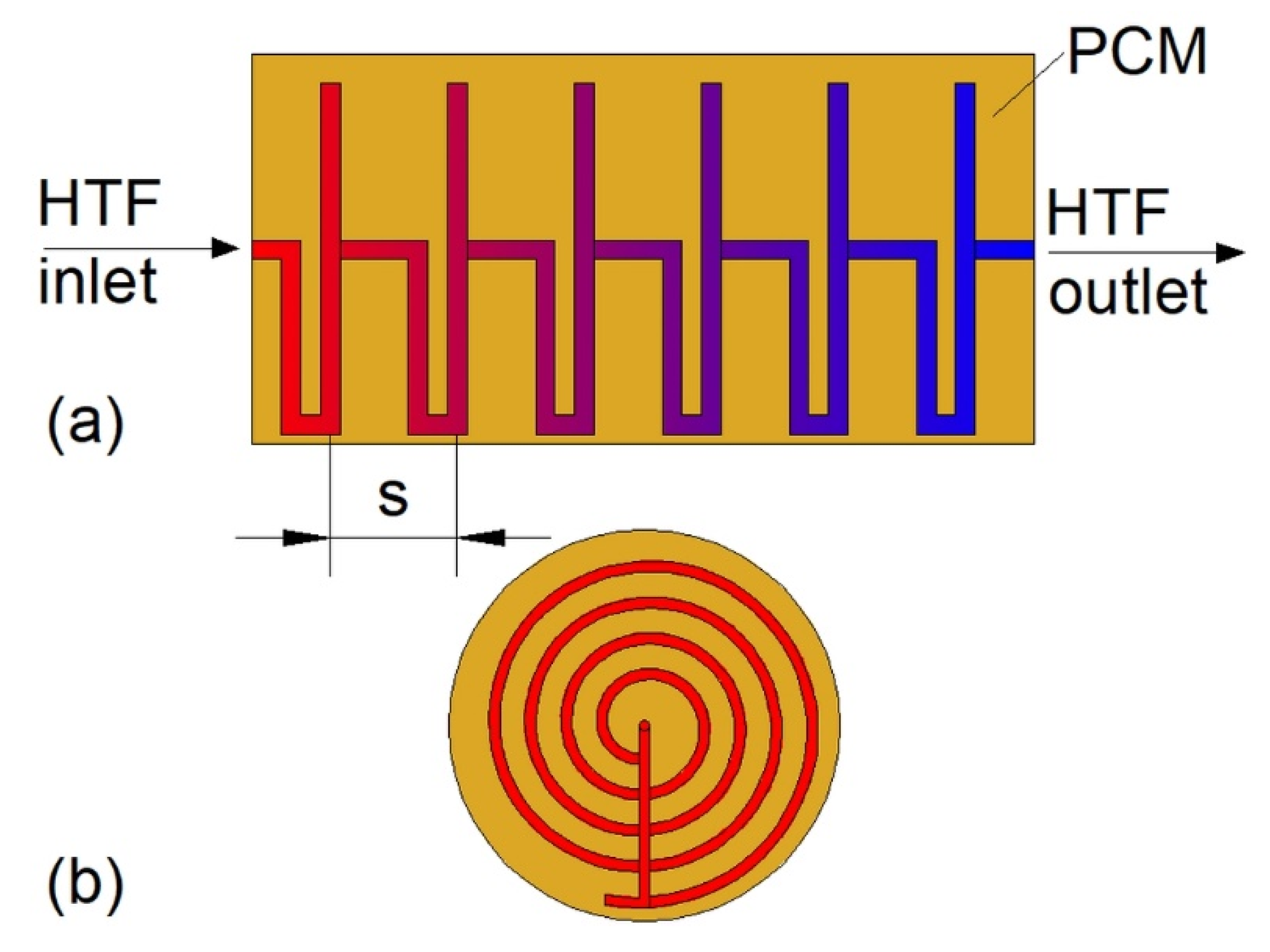
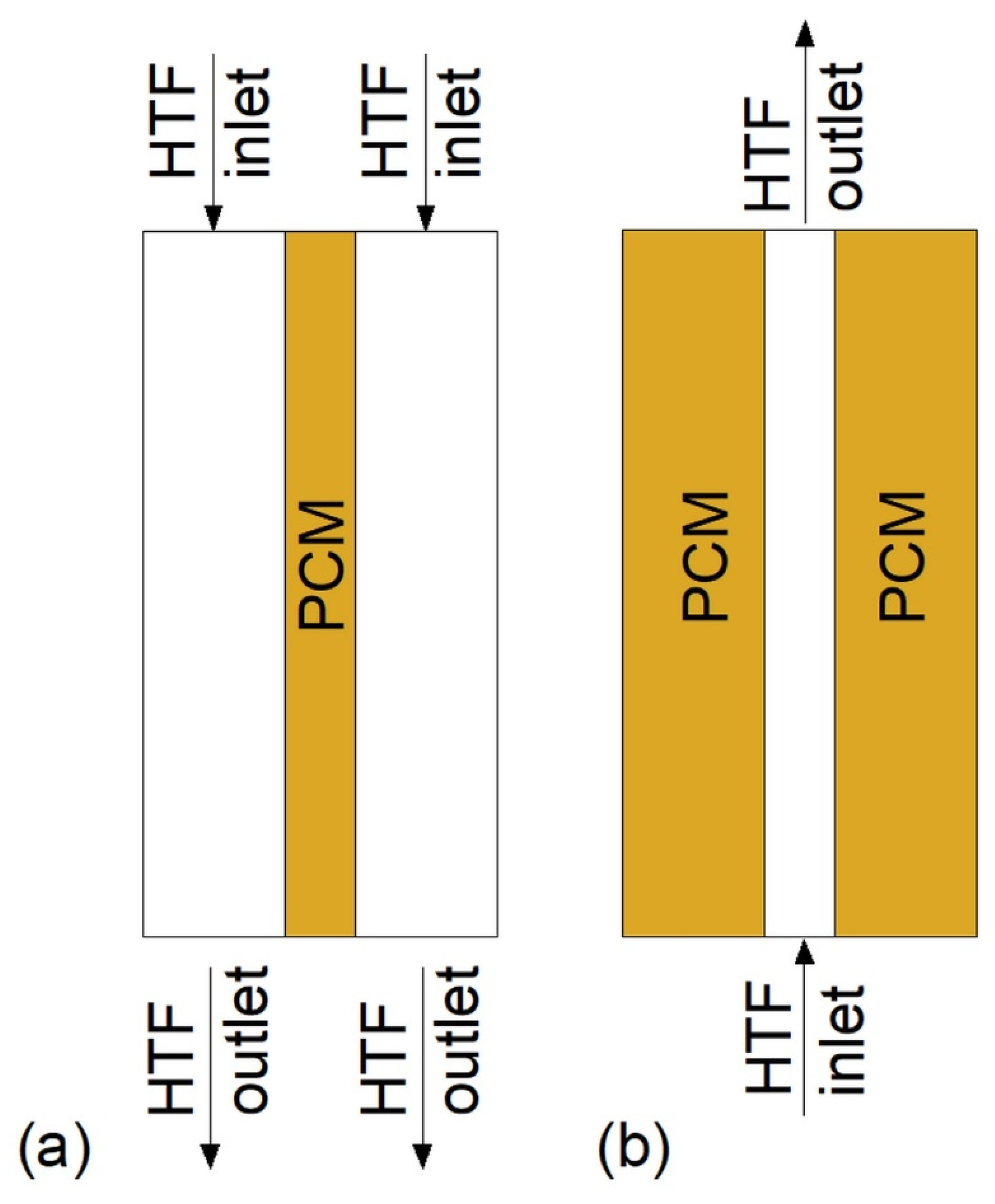
3.1. Plate Heat Exchangers
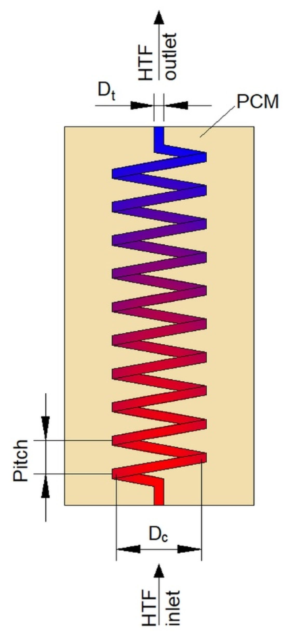
3.2. Helical-Coil Heat Exchangers
3.3. Double-Tube Heat Exchangers
3.4. Triple-Tube Heat Exchangers
3.5. Multi-Tube Heat Exchangers
3.6. Heat Exchangers with Encapsulated PCMs
3.7. Enclosure-Type Heat Exchangers
3.8. Other Types of Heat Exchangers
4. Conclusions
Author Contributions
Funding
Acknowledgments
Conflicts of Interest
Nomenclature
| DTHX | double-tube heat exchanger |
| HCHX | helical-coil heat exchanger |
| HTF | heat transfer fluid |
| HX | heat exchanger |
| LHTES | latent heat thermal energy storage |
| MTHX | multi-tube heat exchanger |
| PCM | phase change material |
| TES | thermal energy storage |
| TTHX | triple-tube heat exchanger |
References
- Su, W.; Darkwa, J.; Kokogiannakis, G. Review of solid-liquid phase change materials and their encapsulation technologies. Renew. Sustain. Energy Rev. 2015, 48, 373–391. [Google Scholar] [CrossRef]
- Lin, Y.; Alva, G.; Fang, G. Review on thermal performances and applications of thermal energy storage systems with inorganic phase change materials. Energy 2018, 165, 685–708. [Google Scholar] [CrossRef]
- Magendran, S.S.; Khan, F.S.A.; Mubarak, N.M.; Vaka, M.; Walvekar, R.; Khalid, M.; Abdullah, E.C.; Nizamuddin, S.; Karri, R.R. Synthesis of organic phase change materials (PCM) for energy storage applications: A review. Nano Struct. Nano Objects 2019, 20, 100399. [Google Scholar] [CrossRef]
- Khan, Z.; Khan, Z.; Ghafoor, A. A review of performance enhancement of PCM based latent heat storage system within the context of materials, thermal stability and compatibility. Energy Convers. Manag. 2016, 115, 132–158. [Google Scholar] [CrossRef]
- Farid, M.M.; Khudhair, A.M.; Razack, S.A.K.; Al-Hallaj, S. A review on phase change energy storage: Materials and applications. Energy Convers. Manag. 2004, 45, 1597–1615. [Google Scholar] [CrossRef]
- Radomska, E.; Mika, L.; Sztekler, K. The impact of additives on the main properties of phase change materials. Energies 2020, 13, 3064. [Google Scholar] [CrossRef]
- Ma, C.; Zhang, Y.; Chen, X.; Song, X.; Tang, K. Experimental study of an enhanced phase change material of paraffin/expanded graphite/nano-metal particles for a personal cooling system. Materials 2020, 13, 980. [Google Scholar] [CrossRef]
- Marcos, M.A.; Cabaleiro, D.; Guimarey, M.J.G.; Comuñas, M.J.P.; Fedele, L.; Fernández, J.; Lugo, L. PEG 400-based phase change materials nano-enhanced with functionalized graphene nanoplatelets. Nanomaterials 2018, 8, 16. [Google Scholar] [CrossRef]
- Rehman, T.; Ali, H.M.; Janjua, M.M.; Sajjad, U.; Yan, W.M. A critical review on heat transfer augmentation of phase change materials embedded with porous materials/foams. Int. J. Heat Mass Transf. 2019, 135, 649–673. [Google Scholar] [CrossRef]
- Li, W.; Dong, Y.; Zhang, X.; Liu, X. Preparation and Performance Analysis of Graphite Additive/Paraffin Composite Phase Change Materials. Processes 2019, 7, 447. [Google Scholar] [CrossRef]
- Kalapala, L.; Devanuri, J.K. Influence of operational and design parameters on the performance of a PCM based heat exchanger for thermal energy storage—A review. J. Energy Storage 2018, 20, 497–519. [Google Scholar] [CrossRef]
- Johnson, M.; Fiss, M.; Klemm, T.; Eck, M. Test and analysis of a flat plate latent heat storage design. Energy Procedia 2014, 57, 662–671. [Google Scholar] [CrossRef]
- Kabbara, M.; Groulx, D.; Joseph, A. A parametric experimental investigation of the heat transfer in a coil-in-tank latent heat energy storage system. Int. J. Therm. Sci. 2018, 130, 395–405. [Google Scholar] [CrossRef]
- Anish, R.; Mariappan, V.; Joybari, M.M.; Abdulateef, A.M. Performance comparison of the thermal behavior of xylitol and erythritol in a double spiral coil latent heat storage system. Therm. Sci. Eng. Prog. 2020, 15, 100441. [Google Scholar] [CrossRef]
- Kousha, N.; Hosseini, M.J.; Aligoodarz, M.R.; Pakrouh, R.; Bahrampoury, R. Effect of inclination angle on the performance of a shell and tube heat storage unit—An experimental study. Appl. Therm. Eng. 2017, 112, 1497–1509. [Google Scholar] [CrossRef]
- Kadivar, M.R.; Moghimi, M.A.; Sapin, P.; Markides, C.N. Annulus eccentricity optimisation of a phase-change material (PCM) horizontal double-pipe thermal energy store. J. Energy Storage 2019, 26, 101030. [Google Scholar] [CrossRef]
- Esapour, M.; Hamzehnezhad, A.; Rabienataj, A.A.; Jourabian, M. Melting and solidification of PCM embedded in porous metal foam in horizontal multi-tube heat storage system. Energy Convers. Manag. 2018, 171, 398–410. [Google Scholar] [CrossRef]
- Saydam, V.; Parsazadeh, M.; Radeef, M.; Duan, X. Design and experimental analysis of a helical coil phase change heat exchanger for thermal energy storage. J. Energy Storage 2019, 21, 9–17. [Google Scholar] [CrossRef]
- Korti, A.I.N.; Tlemsani, F.Z. Experimental investigation of latent heat storage in a coil in PCM storage unit. J. Energy Storage 2016, 5, 177–186. [Google Scholar] [CrossRef]
- Anish, R.; Mariappan, V.; Suresh, S. Experimental investigation on melting and solidification behaviour of erythritol in a vertical double spiral coil thermal energy storage system. Sustain. Cities Soc. 2019, 44, 253–264. [Google Scholar] [CrossRef]
- Pourakabar, A.; Rabienataj Darzi, A.A. Enhancement of phase change rate of PCM in cylindrical thermal energy storage. Appl. Therm. Eng. 2019, 150, 132–142. [Google Scholar] [CrossRef]
- Bellan, S.; Gonzalez-Aguilar, J.; Romero, M.; Rahman, M.M.; Goswami, D.Y.; Stefanakos, E.K.; Couling, D. Numerical analysis of charging and discharging performance of a thermal energy storage system with encapsulated phase change material. Appl. Therm. Eng. 2014, 71, 481–500. [Google Scholar] [CrossRef]
- Medrano, M.; Yilmaz, M.O.; Nogués, M.; Martorell, I.; Roca, J.; Cabeza, L.F. Experimental evaluation of commercial heat exchangers for use as PCM thermal storage systems. Appl. Energy 2009, 86, 2047–2055. [Google Scholar] [CrossRef]
- Elfeky, K.E.; Ahmed, N.; Wang, Q. Numerical comparison between single PCM and multi-stage PCM based high temperature thermal energy storage for CSP tower plants. Appl. Therm. Eng. 2018, 139, 609–622. [Google Scholar] [CrossRef]
- Youssef, W.; Ge, Y.T.; Tassou, S.A. CFD modelling development and experimental validation of a phase change material (PCM) heat exchanger with spiral-wired tubes. Energy Convers. Manag. 2018, 157, 498–510. [Google Scholar] [CrossRef]
- Joshi, V.; Rathod, M.K. Constructal enhancement of thermal transport in latent heat storage systems assisted with fins. Int. J. Therm. Sci. 2019, 145, 105984. [Google Scholar] [CrossRef]
- Tiari, S.; Mahdavi, M.; Qiu, S. Experimental study of a latent heat thermal energy storage system assisted by a heat pipe network. Energy Convers. Manag. 2017, 153, 362–373. [Google Scholar] [CrossRef]
- Karami, R.; Kamkari, B. Experimental investigation of the effect of perforated fins on thermal performance enhancement of vertical shell and tube latent heat energy storage systems. Energy Convers. Manag. 2020, 210, 112679. [Google Scholar] [CrossRef]
- Salyan, S.; Praveen, B.; Singh, H.; Suresh, S.; Reddy, A.S. Liquid Metal Gallium in Metal Inserts for Solar Thermal Energy Storage: A Novel Heat Transfer Enhancement Technique. Sol. Energy Mater. Sol. Cells 2020, 208, 110365. [Google Scholar] [CrossRef]
- Yang, H.; Song, J.; He, B.; Ding, G. Numerical study on charging characteristics of heat pipe-assisted cylindrical capsule for enhancing latent thermal energy storage. Sol. Energy 2019, 190, 147–155. [Google Scholar] [CrossRef]
- Sunku Prasad, J.; Muthukumar, P.; Anandalakshmi, R.; Niyas, H. Comparative study of phase change phenomenon in high temperature cascade latent heat energy storage system using conduction and conduction-convection models. Sol. Energy 2018, 176, 627–637. [Google Scholar] [CrossRef]
- Yang, X.; Xiong, T.; Dong, J.L.; Li, W.X.; Wang, Y. Investigation of the dynamic melting process in a thermal energy storage unit using a helical coil heat exchanger. Energies 2017, 10, 1129. [Google Scholar] [CrossRef]
- Anish, R.; Mariappan, V.; Mastani Joybari, M. Experimental investigation on the melting and solidification behavior of erythritol in a horizontal shell and multi-finned tube latent heat storage unit. Appl. Therm. Eng. 2019, 161, 114194. [Google Scholar] [CrossRef]
- Khan, Z.; Khan, Z.A. Experimental investigations of charging/melting cycles of paraffin in a novel shell and tube with longitudinal fins based heat storage design solution for domestic and industrial applications. Appl. Energy 2017, 206, 1158–1168. [Google Scholar] [CrossRef]
- Wu, S.; Fang, G. Dynamic performances of solar heat storage system with packed bed using myristic acid as phase change material. Energy Build. 2011, 43, 1091–1096. [Google Scholar] [CrossRef]
- Wu, S.; Fang, G.; Liu, X. Dynamic discharging characteristics simulation on solar heat storage system with spherical capsules using paraffin as heat storage material. Renew. Energy 2011, 36, 1190–1195. [Google Scholar] [CrossRef]
- Chen, C.; Zhang, H.; Gao, X.; Xu, T.; Fang, Y.; Zhang, Z. Numerical and experimental investigation on latent thermal energy storage system with spiral coil tube and paraffin/expanded graphite composite PCM. Energy Convers. Manag. 2016, 126, 889–897. [Google Scholar] [CrossRef]
- Mahdi, M.S.; Mahood, H.B.; Khadom, A.A.; Campbell, A.N.; Hasan, M.; Sharif, A.O. Experimental investigation of the thermal performance of a helical coil latent heat thermal energy storage for solar energy applications. Therm. Sci. Eng. Prog. 2019, 10, 287–298. [Google Scholar] [CrossRef]
- Du, R.; Li, W.; Xiong, T.; Yang, X.; Wang, Y.; Shah, K.W. Numerical investigation on the melting of nanoparticle-enhanced PCM in latent heat energy storage unit with spiral coil heat exchanger. Build. Simul. 2019, 12, 869–879. [Google Scholar] [CrossRef]
- Saeed, R.M.; Schlegel, J.P.; Sawafta, R.; Kalra, V. Plate type heat exchanger for thermal energy storage and load shifting using phase change material. Energy Convers. Manag. 2019, 181, 120–132. [Google Scholar] [CrossRef]
- Wang, P.; Wang, X.; Huang, Y.; Li, C.; Peng, Z.; Ding, Y. Thermal energy charging behaviour of a heat exchange device with a zigzag plate configuration containing multi-phase-change-materials (m-PCMs). Appl. Energy 2015, 142, 328–336. [Google Scholar] [CrossRef]
- Watanabe, T.; Kanzawa, A. Second law optimization of a latent heat storage system with PCMS having different melting points. Heat Recover. Syst. CHP 1995, 15, 641–653. [Google Scholar] [CrossRef]
- Aldoss, T.K.; Rahman, M.M. Comparison between the single-PCM and multi-PCM thermal energy storage design. Energy Convers. Manag. 2014, 83, 79–87. [Google Scholar] [CrossRef]
- Mohammadnejad, F.; Hossainpour, S. A CFD modeling and investigation of a packed bed of high temperature phase change materials (PCMs) with different layer configurations. J. Energy Storage 2020, 28, 101209. [Google Scholar] [CrossRef]
- Wang, P.; Li, D.; Huang, Y.; Zheng, X.; Wang, Y.; Peng, Z.; Ding, Y. Numerical Study of Solidification in a Plate Heat Exchange Device with a Zigzag Configuration Containing Multiple Phase-Change-Materials. Energies 2016, 9, 394. [Google Scholar] [CrossRef]
- Kurnia, J.C.; Sasmito, A.P.; Jangam, S.V.; Mujumdar, A.S. Improved design for heat transfer performance of a novel phase change material (PCM) thermal energy storage (TES). Appl. Therm. Eng. 2013, 50, 896–907. [Google Scholar] [CrossRef]
- Domański, R.; Fellah, G. Exergy analysis for the evaluation of a thermal storage system employing PCMS with different mlting temperatures. Appl. Therm. Eng. 1996, 16, 907–919. [Google Scholar] [CrossRef]
- Gong, Z.X.; Mujumdar, A.S. Thermodynamic optimization of the thermal process in energy storage using multiple phase change materials. Appl. Therm. Eng. 1997, 17, 1067–1083. [Google Scholar] [CrossRef]
- Xu, Y.; He, Y.L.; Li, Y.Q.; Song, H.J. Exergy analysis and optimization of charging-discharging processes of latent heat thermal energy storage system with three phase change materials. Sol. Energy 2016, 123, 206–216. [Google Scholar] [CrossRef]
- Tao, Y.B.; He, Y.L.; Liu, Y.K.; Tao, W.Q. Performance optimization of two-stage latent heat storage unit based on entransy theory. Int. J. Heat Mass Transf. 2014, 77, 695–703. [Google Scholar] [CrossRef]
- Guo, Z.Y.; Zhu, H.Y.; Liang, X.G. Entransy-A physical quantity describing heat transfer ability. Int. J. Heat Mass Transf. 2007, 50, 2545–2556. [Google Scholar] [CrossRef]
- Xu, H.J.; Zhao, C.Y. Thermodynamic analysis and optimization of cascaded latent heat storage system for energy efficient utilization. Energy 2015, 90, 1662–1673. [Google Scholar] [CrossRef]
- Xu, H.J.; Zhao, C.Y. Thermal performance of cascaded thermal storage with phase-change materials (PCMs). Part I: Steady cases. Int. J. Heat Mass Transf. 2017, 106, 932–944. [Google Scholar] [CrossRef]
- Xu, H.J.; Zhao, C.Y. Thermal performance of cascaded thermal storage with phase-change materials (PCMs). Part II: Unsteady cases. Int. J. Heat Mass Transf. 2017, 106, 945–957. [Google Scholar] [CrossRef]
- Ezra, M.; Kozak, Y.; Dubovsky, V.; Ziskind, G. Analysis and optimization of melting temperature span for a multiple-PCM latent heat thermal energy storage unit. Appl. Therm. Eng. 2016, 93, 315–329. [Google Scholar] [CrossRef]
- Cheng, X.; Zhai, X. Thermal performance analysis and optimization of a cascaded packed bed cool thermal energy storage unit using multiple phase change materials. Appl. Energy 2018, 215, 566–576. [Google Scholar] [CrossRef]
- Li, Y.Q.; He, Y.L.; Song, H.J.; Xu, C.; Wang, W.W. Numerical analysis and parameters optimization of shell-and-tube heat storage unit using three phase change materials. Renew. Energy 2013, 59, 92–99. [Google Scholar] [CrossRef]
- Li, X.Y.; Yang, L.; Wang, X.L.; Miao, X.Y.; Yao, Y.; Qiang, Q.Q. Investigation on the charging process of a multi-PCM latent heat thermal energy storage unit for use in conventional air-conditioning systems. Energy 2018, 150, 591–600. [Google Scholar] [CrossRef]
- Ahmed, N.; Elfeky, K.E.; Lu, L.; Wang, Q.W. Thermal performance analysis of thermocline combined sensible-latent heat storage system using cascaded-layered PCM designs for medium temperature applications. Renew. Energy 2020, 152, 684–697. [Google Scholar] [CrossRef]
- Zhao, Y.; You, Y.; Liu, H.B.; Zhao, C.Y.; Xu, Z.G. Experimental study on the thermodynamic performance of cascaded latent heat storage in the heat charging process. Energy 2018, 157, 690–706. [Google Scholar] [CrossRef]
- Yuan, F.; Li, M.J.; Ma, Z.; Jin, B.; Liu, Z. Experimental study on thermal performance of high-temperature molten salt cascaded latent heat thermal energy storage system. Int. J. Heat Mass Transf. 2018, 118, 997–1011. [Google Scholar] [CrossRef]
- Peiró, G.; Gasia, J.; Miró, L.; Cabeza, L.F. Experimental evaluation at pilot plant scale of multiple PCMs (cascaded) vs. single PCM configuration for thermal energy storage. Renew. Energy 2015, 83, 729–736. [Google Scholar] [CrossRef]
- GÜREL, B. A numerical investigation of the melting heat transfer characteristics of phase change materials in different plate heat exchanger (latent heat thermal energy storage) systems. Int. J. Heat Mass Transf. 2020, 148, 119117. [Google Scholar] [CrossRef]
- Hoseinzadeh, S.; Ghasemiasl, R.; Havaei, D.; Chamkha, A.J. Numerical investigation of rectangular thermal energy storage units with multiple phase change materials. J. Mol. Liq. 2018, 271, 655–660. [Google Scholar] [CrossRef]
- Liu, M.; Bruno, F.; Saman, W. Thermal performance analysis of a flat slab phase change thermal storage unit with liquid-based heat transfer fluid for cooling applications. Sol. Energy 2011, 85, 3017–3027. [Google Scholar] [CrossRef]
- Vogel, J.; Felbinger, J.; Johnson, M. Natural convection in high temperature flat plate latent heat thermal energy storage systems. Appl. Energy 2016, 184, 184–196. [Google Scholar] [CrossRef]
- Jmal, I.; Baccar, M. Numerical investigation of PCM solidification in a finned rectangular heat exchanger including natural convection. Int. J. Heat Mass Transf. 2018, 127, 714–727. [Google Scholar] [CrossRef]
- Elbahjaoui, R.; El Qarnia, H. Thermal performance of a solar latent heat storage unit using rectangular slabs of phase change material for domestic water heating purposes. Energy Build. 2019, 182, 111–130. [Google Scholar] [CrossRef]
- Rahimi, M.; Hosseini, M.J.; Gorzin, M. Effect of helical diameter on the performance of shell and helical tube heat exchanger: An experimental approach. Sustain. Cities Soc. 2019, 44, 691–701. [Google Scholar] [CrossRef]
- Rahimi, M.; Ardahaie, S.S.; Hosseini, M.J.; Gorzin, M. Energy and exergy analysis of an experimentally examined latent heat thermal energy storage system. Renew. Energy 2020, 147, 1845–1860. [Google Scholar] [CrossRef]
- Ahmadi, R.; Hosseini, M.J.; Ranjbar, A.A.; Bahrampoury, R. Phase change in spiral coil heat storage systems. Sustain. Cities Soc. 2018, 38, 145–157. [Google Scholar] [CrossRef]
- Ardahaie, S.S.; Hosseini, M.J.; Ranjbar, A.A.; Rahimi, M. Energy storage in latent heat storage of a solar thermal system using a novel flat spiral tube heat exchanger. Appl. Therm. Eng. 2019, 159, 113900. [Google Scholar] [CrossRef]
- Mahdi, M.S.; Mahood, H.B.; Campbell, A.N.; Khadom, A.A. Experimental study on the melting behavior of a phase change material in a conical coil latent heat thermal energy storage unit. Appl. Therm. Eng. 2020, 175, 114684. [Google Scholar] [CrossRef]
- Zhang, S.; Zhang, L.; Yang, X.; Yu, X.; Duan, F.; Jin, L.; Meng, X. Experimental Investigation of a Spiral Tube Embedded Latent Thermal Energy Storage Tank Using Paraffin as PCM. Energy Procedia 2017, 105, 4543–4548. [Google Scholar] [CrossRef]
- Tayssir, M.; Eldemerdash, S.M.; Sakr, R.Y.; Elshamy, A.R.; Abdellatif, O.E. Experimental investigation of melting behavior of PCM by using coil heat source inside cylindrical container. J. Electr. Syst. Inf. Technol. 2017, 4, 18–33. [Google Scholar] [CrossRef]
- Ling, Z.; Zeng, G.; Xu, T.; Fang, X.; Zhang, Z. Performance of a Coil-pipe Heat Exchanger Filled with Mannitol for Solar Water Heating System. Energy Procedia 2015, 75, 827–833. [Google Scholar] [CrossRef]
- Chen, G.; Sun, G.; Jiang, D.; Su, Y. Experimental and numerical investigation of the latent heat thermal storage unit with PCM packing at the inner side of a tube. Int. J. Heat Mass Transf. 2020, 152, 119480. [Google Scholar] [CrossRef]
- Han, G.S.; Ding, H.S.; Huang, Y.; Tong, L.G.; Ding, Y.L. A comparative study on the performances of different shell-and-tube type latent heat thermal energy storage units including the effects of natural convection. Int. Commun. Heat Mass Transf. 2017, 88, 228–235. [Google Scholar] [CrossRef]
- Mahdi, M.S.; Mahood, H.B.; Campbell, A.N.; Khadom, A.A. Numerical study on the effect of the location of the phase change material in a concentric double pipe latent heat thermal energy storage unit. Therm. Sci. Eng. Prog. 2019, 11, 40–49. [Google Scholar] [CrossRef]
- Al Siyabi, I.; Khanna, S.; Mallick, T.; Sundaram, S. An experimental and numerical study on the effect of inclination angle of phase change materials thermal energy storage system. Energy Procedia 2019, 23, 57–68. [Google Scholar] [CrossRef]
- Mahdi, M.S.; Mahood, H.B.; Mahdi, J.M.; Khadom, A.A.; Campbell, A.N. Improved PCM melting in a thermal energy storage system of double-pipe helical-coil tube. Energy Convers. Manag. 2020, 203, 112238. [Google Scholar] [CrossRef]
- Mehta, D.S.; Solanki, K.; Rathod, M.K.; Banerjee, J. Thermal performance of shell and tube latent heat storage unit: Comparative assessment of horizontal and vertical orientation. J. Energy Storage 2019, 23, 344–362. [Google Scholar] [CrossRef]
- Mehta, D.S.; Solanki, K.; Rathod, M.K.; Banerjee, J. Influence of orientation on thermal performance of shell and tube latent heat storage unit. Appl. Therm. Eng. 2019, 157, 113719. [Google Scholar] [CrossRef]
- Li, S.; Chen, Y.; Sun, Z. Numerical simulation and optimization of the melting process of phase change material inside horizontal annulus. Energies 2017, 10, 1249. [Google Scholar] [CrossRef]
- Seddegh, S.; Tehrani, S.S.M.; Wang, X.; Cao, F.; Taylor, R.A. Comparison of heat transfer between cylindrical and conical vertical shell-and-tube latent heat thermal energy storage systems. Appl. Therm. Eng. 2018, 130, 1349–1362. [Google Scholar] [CrossRef]
- Sodhi, G.S.; Jaiswal, A.K.; Vigneshwaran, K.; Muthukumar, P. Investigation of charging and discharging characteristics of a horizontal conical shell and tube latent thermal energy storage device. Energy Convers. Manag. 2019, 188, 381–397. [Google Scholar] [CrossRef]
- Agyenim, F.; Eames, P.; Smyth, M. A comparison of heat transfer enhancement in a medium temperature thermal energy storage heat exchanger using fins. Sol. Energy 2009, 83, 1509–1520. [Google Scholar] [CrossRef]
- Scharinger-Urschitz, G.; Walter, H.; Haider, M. Heat transfer in latent high-temperature thermal energy storage systems-experimental investigation. Energies 2019, 12, 1264. [Google Scholar] [CrossRef]
- Mahdi, M.S.; Hasan, A.F.; Mahood, H.B.; Campbell, A.N.; Khadom, A.A.; Karim, A.M.A.; Sharif, A.O. Numerical study and experimental validation of the effects of orientation and configuration on melting in a latent heat thermal storage unit. J. Energy Storage 2019, 23, 456–468. [Google Scholar] [CrossRef]
- Deng, S.; Nie, C.; Wei, G.; Ye, W.B. Improving the melting performance of a horizontal shell-tube latent-heat thermal energy storage unit using local enhanced finned tube. Energy Build. 2019, 183, 161–173. [Google Scholar] [CrossRef]
- Deng, S.; Nie, C.; Jiang, H.; Ye, W.B. Evaluation and optimization of thermal performance for a finned double tube latent heat thermal energy storage. Int. J. Heat Mass Transf. 2019, 130, 532–544. [Google Scholar] [CrossRef]
- Nie, C.; Deng, S.; Liu, J. Effects of fins arrangement and parameters on the consecutive melting and solidification of PCM in a latent heat storage unit. J. Energy Storage 2020, 29, 101319. [Google Scholar] [CrossRef]
- Caron-Soupart, A.; Fourmigué, J.F.; Marty, P.; Couturier, R. Performance analysis of thermal energy storage systems using phase change material. Appl. Therm. Eng. 2016, 98, 1286–1296. [Google Scholar] [CrossRef]
- Pu, L.; Zhang, S.; Xu, L.; Li, Y. Thermal performance optimization and evaluation of a radial finned shell-and-tube latent heat thermal energy storage unit. Appl. Therm. Eng. 2020, 166, 114753. [Google Scholar] [CrossRef]
- Aly, K.A.; El-Lathy, A.R.; Fouad, M.A. Enhancement of solidification rate of latent heat thermal energy storage using corrugated fins. J. Energy Storage 2019, 24, 100785. [Google Scholar] [CrossRef]
- Zhang, C.; Li, J.; Chen, Y. Improving the energy discharging performance of a latent heat storage (LHS) unit using fractal-tree-shaped fins. Appl. Energy 2020, 259, 114102. [Google Scholar] [CrossRef]
- Luo, X.; Liao, S. Numerical study on melting heat transfer in dendritic heat exchangers. Energies 2018, 11, 2504. [Google Scholar] [CrossRef]
- Sheikholeslami, M.; Lohrasbi, S.; Ganji, D.D. Numerical analysis of discharging process acceleration in LHTESS by immersing innovative fin configuration using finite element method. Appl. Therm. Eng. 2016, 107, 154–166. [Google Scholar] [CrossRef]
- Skaalum, J.; Groulx, D. Heat transfer comparison between branching and non-branching fins in a latent heat energy storage system. Int. J. Therm. Sci. 2020, 152, 106331. [Google Scholar] [CrossRef]
- Mahdavi, M.; Tiari, S.; Pawar, V. A numerical study on the combined effect of dispersed nanoparticles and embedded heat pipes on melting and solidification of a shell and tube latent heat thermal energy storage system. J. Energy Storage 2020, 27, 101086. [Google Scholar] [CrossRef]
- Pizzolato, A.; Sharma, A.; Maute, K.; Sciacovelli, A.; Verda, V. Design of effective fins for fast PCM melting and solidification in shell-and-tube latent heat thermal energy storage through topology optimization. Appl. Energy 2017, 208, 210–227. [Google Scholar] [CrossRef]
- Kalapala, L.; Devanuri, J.K. Parametric investigation to assess the melt fraction and melting time for a latent heat storage material based vertical shell and tube heat exchanger. Sol. Energy 2019, 193, 360–371. [Google Scholar] [CrossRef]
- Yang, K.; Zhu, N.; Chang, C.; Yu, H.; Yang, S. Numerical analysis of phase-change material melting in triplex tube heat exchanger. Renew. Energy 2020, 145, 867–877. [Google Scholar] [CrossRef]
- Al-Abidi, A.A.; Mat, S.; Sopian, K.; Sulaiman, M.Y.; Mohammad, A.T. Experimental study of melting and solidification of PCM in a triplex tube heat exchanger with fins. Energy Build. 2014, 68, 33–41. [Google Scholar] [CrossRef]
- Gorzin, M.; Hosseini, M.J.; Rahimi, M.; Bahrampoury, R. Nano-enhancement of phase change material in a shell and multi-PCM-tube heat exchanger. J. Energy Storage 2019, 22, 88–97. [Google Scholar] [CrossRef]
- Shahsavar, A.; Shaham, A.; Talebizadehsardari, P. Wavy channels triple-tube LHS unit with sinusoidal variable wavelength in charging/discharging mechanism. Int. Commun. Heat Mass Transf. 2019, 107, 93–105. [Google Scholar] [CrossRef]
- Mahdi, J.M.; Nsofor, E.C. Melting enhancement in triplex-tube latent thermal energy storage system using nanoparticles-fins combination. Int. J. Heat Mass Transf. 2017, 109, 417–427. [Google Scholar] [CrossRef]
- Mahdi, J.M.; Nsofor, E.C. Solidification enhancement of PCM in a triplex-tube thermal energy storage system with nanoparticles and fins. Appl. Energy 2018, 211, 975–986. [Google Scholar] [CrossRef]
- Abdulateef, A.M.; Abdulateef, J.; Sopian, K.; Mat, S.; Ibrahim, A. Optimal fin parameters used for enhancing the melting and solidification of phase-change material in a heat exchanger unite. Case Stud. Therm. Eng. 2019, 14, 100487. [Google Scholar] [CrossRef]
- Abdulateef, A.M.; Abdulateef, J.; Al-Abidi, A.A.; Sopian, K.; Mat, S.; Mahdi, M.S. A combination of fins-nanoparticle for enhancing the discharging of phase-change material used for liquid desiccant air conditioning unite. J. Energy Storage 2019, 24, 100784. [Google Scholar] [CrossRef]
- Alizadeh, M.; Hosseinzadeh, K.; Shahavi, M.H.; Ganji, D.D. Solidification acceleration in a triplex-tube latent heat thermal energy storage system using V-shaped fin and nano-enhanced phase change material. Appl. Therm. Eng. 2019, 163, 114436. [Google Scholar] [CrossRef]
- Mat, S.; Al-Abidi, A.A.; Sopian, K.; Sulaiman, M.Y.; Mohammad, A.T. Enhance heat transfer for PCM melting in triplex tube with internal-external fins. Energy Convers. Manag. 2013, 74, 223–236. [Google Scholar] [CrossRef]
- Al-Abidi, A.A.; Mat, S.; Sopian, K.; Sulaiman, M.Y. Internal and external fin heat transfer enhancement technique for latent heat thermal energy storage in triplex tube heat exchangers. Appl. Therm. Eng. 2013, 53, 147–156. [Google Scholar] [CrossRef]
- Mahdi, J.M.; Lohrasbi, S.; Ganji, D.D.; Nsofor, E.C. Accelerated melting of PCM in energy storage system via novel configuration of fins in the triplex-tube heat exchanger. Int. J. Heat Mass Transf. 2018, 124, 663–676. [Google Scholar] [CrossRef]
- Zarei, M.J.; Bazai, H.; Sharifpur, M.; Mahian, O.; Shabani, B. The Effects of Fin Parameters on the Solidification of PCMs in a Fin-Enhanced Thermal Energy Storage System. Energies 2020, 13, 198. [Google Scholar] [CrossRef]
- Eslamnezhad, H.; Rahimi, A.B. Enhance heat transfer for phase-change materials in triplex tube heat exchanger with selected arrangements of fins. Appl. Therm. Eng. 2017, 113, 813–821. [Google Scholar] [CrossRef]
- Mahdi, J.M.; Nsofor, E.C. Melting enhancement in triplex-tube latent heat energy storage system using nanoparticles-metal foam combination. Appl. Energy 2017, 191, 22–34. [Google Scholar] [CrossRef]
- Mahdi, J.M.; Nsofor, E.C. Solidification enhancement in a triplex-tube latent heat energy storage system using nanoparticles-metal foam combination. Energy 2017, 126, 501–512. [Google Scholar] [CrossRef]
- Kousha, N.; Rahimi, M.; Pakrouh, R.; Bahrampoury, R. Experimental investigation of phase change in a multitube heat exchanger. J. Energy Storage 2019, 23, 292–304. [Google Scholar] [CrossRef]
- Sodhi, G.S.; Vigneshwaran, K.; Jaiswal, A.K.; Muthukumar, P. Assessment of heat transfer characteristics of a latent heat thermal energy storage system: Multi tube design. Energy Procedia 2019, 158, 4677–4683. [Google Scholar] [CrossRef]
- Esapour, M.; Hosseini, M.J.; Ranjbar, A.A.; Bahrampoury, R. Numerical study on geometrical specifications and operational parameters of multi-tube heat storage systems. Appl. Therm. Eng. 2016, 109, 351–363. [Google Scholar] [CrossRef]
- Kuboth, S.; König-Haagen, A.; Brüggemann, D. Numerical analysis of shell-and-tube type latent thermal energy storage performance with different arrangements of circular fins. Energies 2017, 10, 274. [Google Scholar] [CrossRef]
- Bhagat, K.; Prabhakar, M.; Saha, S.K. Estimation of thermal performance and design optimization of finned multitube latent heat thermal energy storage. J. Energy Storage 2018, 19, 135–144. [Google Scholar] [CrossRef]
- Esapour, M.; Hosseini, M.J.; Ranjbar, A.A.; Pahamli, Y.; Bahrampoury, R. Phase change in multi-tube heat exchangers. Renew. Energy 2016, 85, 1017–1025. [Google Scholar] [CrossRef]
- Raul, A.K.; Bhavsar, P.; Saha, S.K. Experimental study on discharging performance of vertical multitube shell and tube latent heat thermal energy storage. J. Energy Storage 2018, 20, 279–288. [Google Scholar] [CrossRef]
- He, Z.; Wang, X.; Du, X.; Amjad, M.; Yang, L.; Xu, C. Experiments on comparative performance of water thermocline storage tank with and without encapsulated paraffin wax packed bed. Appl. Therm. Eng. 2019, 147, 188–197. [Google Scholar] [CrossRef]
- Wu, S.; Fang, G.; Liu, X. Thermal performance simulations of a packed bed cool thermal energy storage system using n-tetradecane as phase change material. Int. J. Therm. Sci. 2010, 49, 1752–1762. [Google Scholar] [CrossRef]
- Karthikeyan, S.; Solomon, G.R.; Kumaresan, V.; Velraj, R. Parametric studies on packed bed storage unit filled with PCM encapsulated spherical containers for low temperature solar air heating applications. Energy Convers. Manag. 2014, 78, 74–80. [Google Scholar] [CrossRef]
- Li, M.-J.; Jin, B.; Ma, Z.; Yuan, F. Experimental and numerical study on the performance of a new high-temperature packed-bed thermal energy storage system with macroencapsulation of molten salt phase change material. Appl. Energy 2018, 221, 1–15. [Google Scholar] [CrossRef]
- Raul, A.; Jain, M.; Gaikwad, S.; Saha, S.K. Modelling and experimental study of latent heat thermal energy storage with encapsulated PCMs for solar thermal applications. Appl. Therm. Eng. 2018, 143, 415–428. [Google Scholar] [CrossRef]
- Mawire, A.; Lefenya, T.M.; Ekwomadu, C.S.; Lentswe, K.A.; Shobo, A.B. Performance comparison of medium temperature domestic packed bed latent heat storage systems. Renew. Energy 2020, 146, 1897–1906. [Google Scholar] [CrossRef]
- Al Siyabi, I.; Khanna, S.; Mallick, T.; Sundaram, S. Multiple Phase Change Material (PCM) Configuration for PCM-Based Heat Sinks-An Experimental Study. Energies 2018, 11, 1629. [Google Scholar] [CrossRef]
- Sinks, M.H.; Singh, P.; Khanna, S.; Newar, S.; Sharma, V.; Reddy, K.S.; Khusainov, R. Solar Photovoltaic Panels with Finned Phase Change. Energies 2020, 13, 2558. [Google Scholar] [CrossRef]
- Ren, Q.; Xu, H.; Luo, Z. PCM charging process accelerated with combination of optimized triangle fins and nanoparticles. Int. J. Therm. Sci. 2019, 140, 466–479. [Google Scholar] [CrossRef]
- Kamkari, B.; Amlashi, H.J. Numerical simulation and experimental verification of constrained melting of phase change material in inclined rectangular enclosures. Int. Commun. Heat Mass Transf. 2017, 88, 211–219. [Google Scholar] [CrossRef]
- Kamkari, B.; Groulx, D. Experimental investigation of melting behaviour of phase change material in finned rectangular enclosures under different inclination angles. Exp. Therm. Fluid Sci. 2018, 97, 94–108. [Google Scholar] [CrossRef]
- Karami, R.; Kamkari, B. Investigation of the effect of inclination angle on the melting enhancement of phase change material in finned latent heat thermal storage units. Appl. Therm. Eng. 2019, 146, 45–60. [Google Scholar] [CrossRef]
- Abdi, A.; Martin, V.; Chiu, J.N.W. Numerical investigation of melting in a cavity with vertically oriented fins. Appl. Energy 2019, 235, 1027–1040. [Google Scholar] [CrossRef]
- Ji, C.; Qin, Z.; Low, Z.; Dubey, S.; Choo, F.H.; Duan, F. Non-uniform heat transfer suppression to enhance PCM melting by angled fins. Appl. Therm. Eng. 2018, 129, 269–279. [Google Scholar] [CrossRef]
- Ladekar, C.L.; Chaudhary, S.K.; Khandare, S.S. Experimental Investigate for Optimization of Heat Pipe Performance in Latent Heat Thermal Energy Storage. Mater. Today Proc. 2017, 4, 8149–8157. [Google Scholar] [CrossRef]
- Motahar, S.; Khodabandeh, R. Experimental study on the melting and solidification of a phase change material enhanced by heat pipe. Int. Commun. Heat Mass Transf. 2016, 73, 1–6. [Google Scholar] [CrossRef]
- Huang, Q.; Li, X.; Zhang, G.; Zhang, J.; He, F.; Li, Y. Experimental investigation of the thermal performance of heat pipe assisted phase change material for battery thermal management system. Appl. Therm. Eng. 2018, 141, 1092–1100. [Google Scholar] [CrossRef]
- Jiang, Z.Y.; Qu, Z.G. Lithium–ion battery thermal management using heat pipe and phase change material during discharge–charge cycle: A comprehensive numerical study. Appl. Energy 2019, 242, 378–392. [Google Scholar] [CrossRef]
- Duan, J.; Xiong, Y.; Yang, D. On the melting process of the phase change material in horizontal rectangular enclosures. Energies 2019, 12, 3100. [Google Scholar] [CrossRef]
- Robak, C.W.; Bergman, T.L.; Faghri, A. Enhancement of latent heat energy storage using embedded heat pipes. Int. J. Heat Mass Transf. 2011, 54, 3476–3484. [Google Scholar] [CrossRef]
- Sharifi, N.; Wang, S.; Bergman, T.L.; Faghri, A. Heat pipe-assisted melting of a phase change material. Int. J. Heat Mass Transf. 2012, 55, 3458–3469. [Google Scholar] [CrossRef]
- Sharifi, N.; Bergman, T.L.; Allen, M.J.; Faghri, A. Melting and solidification enhancement using a combined heat pipe, foil approach. Int. J. Heat Mass Transf. 2014, 78, 930–941. [Google Scholar] [CrossRef]
- Lin, W.; Huang, R.; Fang, X.; Zhang, Z. Improvement of thermal performance of novel heat exchanger with latent heat storage. Int. J. Heat Mass Transf. 2019, 140, 877–885. [Google Scholar] [CrossRef]
- Lin, W.; Wang, Q.; Fang, X.; Gao, X.; Zhang, Z. Experimental and numerical investigation on the novel latent heat exchanger with paraffin/expanded graphite composite. Appl. Therm. Eng. 2018, 144, 836–844. [Google Scholar] [CrossRef]
- Khan, Z.; Khan, Z.; Tabeshf, K. Parametric investigations to enhance thermal performance of paraffin through a novel geometrical configuration of shell and tube latent thermal storage system. Energy Convers. Manag. 2016, 127, 355–365. [Google Scholar] [CrossRef]
- Ebrahimi, A.; Hosseini, M.J.; Ranjbar, A.A.; Rahimi, M.; Bahrampoury, R. Melting process investigation of phase change materials in a shell and tube heat exchanger enhanced with heat pipe. Renew. Energy 2019, 138, 378–394. [Google Scholar] [CrossRef]
- Khan, Z.; Khan, Z.A. An experimental investigation of discharge/solidification cycle of paraffin in novel shell and tube with longitudinal fins based latent heat storage system. Energy Convers. Manag. 2017, 154, 157–167. [Google Scholar] [CrossRef]
- Khan, Z.; Khan, Z.A. Thermodynamic performance of a novel shell-and-tube heat exchanger incorporating paraffin as thermal storage solution for domestic and commercial applications. Appl. Therm. Eng. 2019, 160, 114007. [Google Scholar] [CrossRef]
- Besagni, G.; Croci, L. Experimental study of a pilot-scale fin-and-tube phase change material storage. Appl. Therm. Eng. 2019, 160, 114089. [Google Scholar] [CrossRef]
- Pakalka, S.; Valančius, K.; Streckienė, G. Experimental comparison of the operation of PCM-based copper heat exchangers with different configurations. Appl. Therm. Eng. 2020, 172, 115138. [Google Scholar] [CrossRef]
- Talukdar, S.; Afroz, H.M.M.; Hossain, M.A.; Aziz, M.A.; Hossain, M.M. Heat transfer enhancement of charging and discharging of phase change materials and size optimization of a latent thermal energy storage system for solar cold storage application. J. Energy Storage 2019, 24, 100797. [Google Scholar] [CrossRef]
- Amagour, M.E.H.; Rachek, A.; Bennajah, M.; Ebn Touhami, M. Experimental investigation and comparative performance analysis of a compact finned-tube heat exchanger uniformly filled with a phase change material for thermal energy storage. Energy Convers. Manag. 2018, 165, 137–151. [Google Scholar] [CrossRef]


| Reference | Number of PCMs | Type of PCM | Melting Temperature of PCM, (°C) | Ratio of PCMs | Type of Research | Investigated Process |
|---|---|---|---|---|---|---|
| Elfeky et al. [24] | 3 | MgCl2–KCl–NaCl | 505 | 1:1:1 (volume) | Numerical | Melting Solidification |
| MgCl2–NaCl | 440 | |||||
| Li2CO3–K2CO3 | 382 | |||||
| Sunku Prasad et al. [31] | 3 | KOH | 360 | 1:1:1 (volume) | Numerical | Melting Solidification |
| KNO3 | 335 | |||||
| NaNO3 | 306 | |||||
| Wang et al. [41] | 3 | Not available | Not available | 1:1:1 16:6:8 (mass) | Numerical | Melting |
| Aldoss and Rahman [43] | 2, 3 | Not available | 42–44 | 1:1 1:1:1 (volume) | Numerical | Melting Solidification |
| 50–52 | ||||||
| 60–62 | ||||||
| Mohammadnejad and Hossainpour [44] | 3 | KOH | 378–380 | Not available | Numerical | Solidification |
| KNO3 | 333–336 | |||||
| NaNO2 | 277–304 | |||||
| Wang et al. [45] | 3 | NaCl-MgCl2 | Not available | 1:1:1 (mass) | Numerical | Solidification |
| Kurnia et al. [46] | 3 | Not available | 46–48 | Not available | Numerical | Melting Solidification |
| 26–28 | ||||||
| 36–38 | ||||||
| Gong and Mujumdar [48] | 2, 3, 5 | Not available | Not available | Not available | Numerical | Melting Solidification |
| Xu et al. [49] | 3 | Li2CO3–K2CO3 | 488 | Not available | Numerical | Melting Solidification |
| NaNO3 | 307 | |||||
| NaNO3–KNO3 | 220 | |||||
| Tao et al. [50] | 2 | LiF–CaF2 | 767 | 1:1 (volume) | Numerical | Melting |
| LiF–MgF2 | 746 | |||||
| Ezra et al. [55] | 2–180 | Not available | Not available | 1:1 (mass) | Numerical | Melting |
| Cheng and Zhai [56] | 3 | PCM1 1 | 13 | 1:1:1 (volume) | Numerical Experimental | Solidification |
| PCM2 1 | 14.5 | |||||
| PCM3 1 | 17 | |||||
| Li et al. [57] | 3 | K2CO3–Na2CO3 | 710 | 5:4:3 3:4:5 2.5:4:5.5 (volume) | Numerical | Melting |
| Li2CO3–Na2CO3–K2CO3 | 550 | |||||
| Li2CO3–K2CO3–Na2CO3 | 397 | |||||
| Li et al. [58] | 3 | HS-W1 | 5.3 | 2 | Numerical Experimental | Solidification |
| HS-W2 | 6.5 | |||||
| Paraffin C15 | 10.0 | |||||
| Ahmed et al. [59] | 3 | Galactitol | 187 | 1:8:1 2.5:5:2.5 4:2:4 (volume) | Numerical | Melting Solidification |
| D-mannitol | 165 | |||||
| Mixture of galactitol and d-mannitol | 153 | |||||
| Zhao et al. [60] | 3 | NaNO3 | 100 | 1:1:1 (mass) | Experimental | Melting |
| NaNO3–Ca(NO3)2 | 200 | |||||
| NaNO3–KNO3–LiNO3 | 300 | |||||
| Yuan et al. [61] | 3 | Li2CO3–K2CO3 3 | 500 | 1:1:1 (volume) | Experimental | Melting Solidification |
| Li2CO3–K2CO3 4 | 484 | |||||
| Li2CO3–K2CO3–Na2CO3 | 422 | |||||
| Peiró et al. [62] | 2 | Hydroquinone | 165–172 | Not available | Experimental | Melting |
| D-mannitol | 155–162 |
| Reference | PCM | HTF | Type of Research | Investigated Process | HX Orientation | Flow Direction | Parameters Influencing or Heat Transfer Enhancement Technique |
|---|---|---|---|---|---|---|---|
| Johnson et al. [12] | KNO3–NaNO3 | Mobiltherm 603 | Numerical Experimental | Solidification | Vertical | Not available | HTF inlet temperature |
| HTF flow rate | |||||||
| The addition of heat transfer structures | |||||||
| Medrano et al. [23] | Rubitherm RT35 | Water | Experimental | Melting Solidification | Not available | Not available | Types of HXs |
| HTF inlet temperature | |||||||
| HTF flow rate | |||||||
| Saeed et al. [40] | Hexadecane | Water | Experimental | Melting Solidification | Not available | Not available | Number of plates |
| HTF inlet temperature | |||||||
| HTF flow rate | |||||||
| Gürel [63] | RT35 N-octadecane | Water | Numerical | Melting | Horizontal | Downward | Number of plates |
| HTF inlet temperature | |||||||
| PCM layer thickness | |||||||
| Hoseinzadeh et al. [64] | CaCl2∙6H2O RT25 | Air | Numerical | Melting | Horizontal | - | Multiple PCMs |
| Geometrical parameters of HX | |||||||
| HTF inlet temperature | |||||||
| HTF inlet velocity | |||||||
| Liu et al. [65] | Not available | Glycol | Numerical | Melting | Not available | Not available | HTF inlet temperature |
| HTF flow rate | |||||||
| Dimensions of the HX | |||||||
| Vogel et al. [66] | KNO3–NaNO3 | Thermal oil | Numerical Experimental | Melting | Vertical | Downward (melting) Upward (solidification) | Dimensions of the HX |
| Jmal and Baccar [67] | Paraffin C18 RT27 | Air | Numerical | Solidification | Horizontal | - | Number of fins |
| Elbahjaoui and El Qarnia [68] | RT42 RT50 RT60 | Water | Numerical | Melting Solidification | Vertical | Downward | Number of PCM slabs |
| HTF flow rate |
| Reference | PCM | HTF | Type of Research | Investigated Process | HX Orientation | Flow Direction | Parameters Influencing or Heat Transfer Enhancement Technique |
|---|---|---|---|---|---|---|---|
| Kabbara et al. [13] | Dodecanoic acid | Water (solidification) Water–glycol (melting) | Experimental | Melting Solidification | Vertical | Downward (solidification) Upward (melting) | HTF inlet temperature |
| HTF flow rate | |||||||
| Anish et al. [14] | Erythritol Xylitol | Therminol-55 | Experimental | Melting Solidification | Vertical | Downward Upward | Type of a PCM |
| HTF inlet temperature | |||||||
| HTF flow rate | |||||||
| Saydam et al. [18] | Paraffin wax | Ethylene glycol–water mixture | Experimental | Melting Solidification | Vertical | Upward Downward | HTF inlet temperature |
| HTF flow rate | |||||||
| HTF flow direction | |||||||
| Korti and Tlemsani [19] | Refined paraffin wax Semi-refined paraffin wax Classical paraffin wax | Water | Experimental | Melting Solidification | Vertical | Downward | HTF inlet temperature |
| HTF flow rate | |||||||
| Type of a PCM | |||||||
| Anish et al. [20] | Erythritol | Therminol-55 | Experimental | Melting Solidification | Vertical | Downward Upward | HTF inlet temperature |
| HTF flow rate | |||||||
| Rahimi et al. [69] | RT-35 | Water | Experimental | Melting | Horizontal | - | HTF inlet temperature |
| Helical-coil diameter | |||||||
| Mahdi et al. [73] | Paraffin wax | Water | Experimental | Melting | Vertical | Upward | Coil geometry |
| HTF inlet temperature | |||||||
| Mahdi et al. [38] | Paraffin wax | Water | Experimental | Melting Solidification | Vertical | Upward | HTF inlet temperature |
| HTF flow rate | |||||||
| Salyan et al. [28] | D-mannitol D-mannitol with gallium | Therminol 55 | Experimental | Melting Solidification | Vertical | Not available | Addition of metal inserts |
| HTF inlet temperature | |||||||
| HTF flow rate | |||||||
| Yang et al. [32] | RT54HC/expanded graphite | Water | Numerical Experimental | Melting | Vertical | Not available | HTF inlet temperature |
| HTF flow rate | |||||||
| Chen et al. [37] | Paraffin with expanded graphite | Water | Numerical Experimental | Melting | Horizontal | - | HTF inlet temperature |
| HTF flow rate | |||||||
| Helical-coil diameter | |||||||
| Du et al. [39] | Paraffin Paraffin with copper nanoparticles | Water | Numerical Experimental | Melting | Vertical | Downward | Nano-enhanced PCM |
| HTF inlet temperature | |||||||
| HTF flow rate | |||||||
| Rahimi et al. [70] | RT35 | Water | Experimental | Melting | Horizontal | - | Helical-coil diameter |
| HTF inlet temperature | |||||||
| Ahmadi et al. [71] | RT50 | Water | Numerical | Melting | Horizontal | - | Helical-coil diameter |
| Tube diameter | |||||||
| HTF inlet temperature | |||||||
| HTF flow rate | |||||||
| Ardahaie et al. [72] | RT35 | Water | Numerical | Melting | Horizontal 45° Vertical | Upward | Helical-coil geometry |
| Inclination angle | |||||||
| HTF inlet temperature | |||||||
| HTF flow rate | |||||||
| Zhang et al. [74] | RT54 with 3 wt.% of carbon fiber | Water | Experimental | Melting Solidification | Vertical | Not available | HTF inlet temperature |
| HTF flow rate | |||||||
| Tayssir et al. [75] | Paraffin wax | Water | Experimental | Melting | Vertical | Not available | HTF inlet temperature |
| HTF flow rate | |||||||
| Ling et al. [76] | Mannitol | Thermal oil (melting), Water (solidification) | Experimental | Melting Solidification | Vertical | Not available | HTF inlet temperature |
| HTF flow rate |
| Reference | PCM | HTF | Type of Research | Investigated Process | HX Orientation | HTF Location, (Flow Direction) | Parameters Influencing or Heat Transfer Enhancement Technique |
|---|---|---|---|---|---|---|---|
| Kousha et al. [15] | RT35 | Water | Numerical Experimental | Melting Solidification | 0–90° | Inner tube, (not available) | Inclination angle |
| HTF inlet temperature | |||||||
| Kadivar et al. [16] | N-eicosane RT31 RT35 RT44HC | 1 | Numerical | Melting Solidification | Horizontal | Inner tube, (-) | Inner tube eccentricity |
| PCM type | |||||||
| The ratio of the shell to tube diameter | |||||||
| Mehta et al. [82] | Stearic acid | Water | Numerical Experimental | Melting Solidification | Horizontal Vertical | Inner tube, (upward) | Inclination angle |
| HTF inlet temperature | |||||||
| Karami and Kamkari [29] | Lauric acid | Water | Experimental | Melting | Vertical | Inner tube, (upward) | Fins |
| HTF inlet temperature | |||||||
| HTF flow rate | |||||||
| Mahdi et al. [89] | Paraffin wax | Water | Numerical Experimental | Melting | Horizontal Vertical | Inner tube, (not available) | Fins |
| Inclination angle | |||||||
| HTF flow rate | |||||||
| HTF inlet temperature | |||||||
| Al Siyabi et al. [80] | RT35 | Water | Numerical Experimental | Melting | Horizontal Vertical 45° | Inner tube, (not available) | Inclination angle |
| HTF inlet temperature | |||||||
| HTF flow rate | |||||||
| Chen et al. [77] | RT50 | Water | Numerical Experimental | Melting Solidification | Horizontal | Inner tube Annulus, (-) | PCM location |
| HX shape | |||||||
| Han et al. [78] | Solar salt | Air | Numerical | Melting | Horizontal Vertical | Inner tube Annulus, (downward and upward) | PCM location |
| Inclination angle | |||||||
| HTF flow direction | |||||||
| Mahdi et al. [79] | RT50 | 1 | Numerical | Melting Solidification | Horizontal | Inner tube Annulus, (-) | PCM location |
| HTF inlet temperature | |||||||
| Mahdi et al. [81] | RT50 | Water | Numerical | Melting | Vertical | Not available | Shape of HX |
| HTF inlet temperature | |||||||
| HTF flow rate | |||||||
| Mehta et al. [83] | Stearic acid | Water | Experimental | Melting | 0–90° | Inner tube, (upward) | Inclination angle |
| Li et al. [84] | RT27 | Water | Numerical | Melting | Horizontal | Inner tube, (-) | Inner tube eccentricity |
| Inner tube diameter | |||||||
| HTF inlet temperature | |||||||
| Seddegh et al. [85] | RT60 | Water | Numerical Experimental | Melting Solidification | Vertical | Inner tube, (not available) | Geometric design |
| Sodhi et al. [86] | NaNO3 | Air | Numerical | Melting Solidification | Horizontal | Inner tube, (-) | Shape of HX |
| HTF inlet temperature | |||||||
| HTF velocity | |||||||
| Fins | |||||||
| Agyenim et al. [87] | Erythritol | Silicon oil | Experimental | Melting Solidification | Horizontal | Inner tube, (-) | Fins |
| Scharinger-Urschitz et al. [88] | Sodium nitrate | Thermal oil | Experimental | Melting Solidification | Vertical | Inner tube, (upward) | Fins |
| Deng et al. [91] | Lauric acid | 1 | Numerical | Melting | Horizontal | Inner tube, (-) | Fin arrangement |
| Fin number | |||||||
| Fin length | |||||||
| HTF inlet temperature | |||||||
| Nie et al. [92] | Lauric acid | 1 | Numerical | Melting Solidification | Horizontal | Inner tube, (-) | Fin arrangement |
| Fin number | |||||||
| Fin length | |||||||
| Deng et al. [90] | Lauric acid | 1 | Numerical | Melting | Horizontal | Inner tube, (-) | Fin arrangement |
| Fin length | |||||||
| HTF inlet temperature | |||||||
| Caron-Soupart et al. [93] | RT35-HC | Water | Experimental | Melting Solidification | Vertical | Inner tube, (downward-melting; upward-solidification) | Fins |
| Pu et al. [94] | RT35 | Water | Numerical | Melting | Vertical | Inner tube, (downward) | Fin number |
| Fin length | |||||||
| Fin arrangement | |||||||
| Aly et al. [95] | Formic acid | 1 | Numerical | Solidification | Horizontal | Inner tube, (-) | Fin shape |
| Zhang et al. [96] | Lauric acid | 1 | Numerical | Melting Solidification | Horizontal | Inner tube, (-) | Fin shape |
| Luo and Liao [97] | Lauric acid | 1 | Numerical | Melting | Vertical | Inner tube, (-) | Fin shape |
| Sheikholeslami et al. [98] | Water Water with copper nanoparticles | 1 | Numerical | Solidification | Not available | Inner tube, (-) | Fin shape |
| Mahdavi et al. [100] | RT55 | Not available | Numerical | Melting Solidification | Vertical | Inner tube, (upward) | Number of heat pipes |
| Pizzolato et al. [101] | Not available | 1 | Numerical | Melting Solidification | Horizontal | Inner tube, (-) | Fin shape |
| Kalapa and Devanuri [102] | Lauric acid | Not available | Numerical | Melting | Vertical | Inner tube, (downward) | HTF inlet parameters |
| HX dimensions |
| Reference | PCM | HTF | Type of Research | Investigated Process | HX Orientation | HTF Location, (Flow Direction) | Parameters Influencing or Heat Transfer Enhancement Technique |
|---|---|---|---|---|---|---|---|
| Al-Abidi et al. [104] | RT82 | Water | Experimental | Melting Solidification | Horizontal | Inner and outer tube, (-) | HTF inlet temperature |
| HTF flow rate | |||||||
| Chen et al. [77] | RT50 | Water | Numerical Experimental | Melting Solidification | Horizontal | Middle tube, (-) | HX shape |
| Yang et al. [103] | Ba(OH)2∙8H2O | Water | Numerical | Melting | Not available | Inner and outer tube, (not available) | HTF inlet temperature |
| HTF flow rate | |||||||
| Gorzin et al. [105] | RT50 | Not available | Numerical | Solidification | Not available | Middle tube, (-) | HX shape |
| HTF inlet temperature | |||||||
| Shahsavar et al. [106] | RT35 | Water | Numerical | Melting Solidification | Vertical | Inner tube (upward), outer tube (downward) | HX shape |
| Abdulateef et al. [109] | RT82 | Water | Numerical Experimental | Melting Solidification | Not available | Inner and outer tube, (-) | Number of fins |
| Fin length | |||||||
| Fin thickness | |||||||
| Abdulateef et al. [110] | RT82 | Not available | Numerical Experimental | Solidification | Horizontal | Inner and outer tube, (-) | Fin shape |
| HTF flow rate | |||||||
| Alizadeh et al. [111] | Water | Not available | Numerical | Solidification | Not available | Inner and outer tube, (not available) | Fin length |
| Fin thickness | |||||||
| Shape of fins | |||||||
| Al-Abidi et al. [113] | RT82 | Water | Numerical | Melting | Horizontal | Inner and outer tube, (-) | Number of fins |
| Fin length | |||||||
| Fin thickness | |||||||
| Mat et al. [112] | RT82 | Water | Numerical | Melting | Horizontal | Inner tube Outer tube Inner and outer tube, (-) | Fin arrangement |
| Fin length | |||||||
| HTF inlet temperature | |||||||
| Mahdi and Nsofor [107] | RT82 | Water | Numerical | Melting | Horizontal | Inner and outer tube, (-) | Fin length |
| Fin thickness | |||||||
| HTF inlet temperature | |||||||
| Mahdi and Nsofor [108] | RT82 | Water | Numerical | Solidification | Horizontal | Inner and outer tube, (-) | Fin length |
| Fin thickness | |||||||
| Mahdi et al. [114] | RT82 | Not available | Numerical | Melting | Horizontal | Inner and outer tube, (-) | Number of fins |
| Fin length | |||||||
| Fin arrangement | |||||||
| Zarei et al. [115] | RT82 | Water | Numerical | Solidification | Horizontal | Inner and outer tube, (-) | Fin arrangement |
| Eslamnezhad et al. [116] | RT82 | Water | Numerical | Melting | Horizontal | Inner and outer tube, (-) | Fin arrangement |
| Eccentricity of the inner tube | |||||||
| Mahdi and Nsofor [117] | RT82 | Water | Numerical | Melting | Horizontal | Inner and outer tube, (-) | Copper foam porosity |
| HTF inlet temperature | |||||||
| Mahdi and Nosfor [118] | RT82 | Water | Numerical | Solidification | Horizontal | Inner and outer tube, (-) | Copper foam porosity |
| Reference | PCM | HTF | Type of Research | Investigated Process | HX Orientation | HTF Location, (Flow Direction) | Parameters Influencing or Heat Transfer Enhancement Technique |
|---|---|---|---|---|---|---|---|
| Esapour et al. [17] | RT35 | Water | Numerical | Melting Solidification | Horizontal | Inner tubes and space between outer and middle tubes, (-) | Number of tubes |
| Arrangement of tubes | |||||||
| Copper foam | |||||||
| Copper foam porosity | |||||||
| Pourakabar and Rabienataj Darzi [21] | N-eicosane | Not available | Numerical | Melting Solidification | Horizontal | Inner tubes, (-) | The shape of the shell |
| Number of tubes | |||||||
| Arrangement of tubes | |||||||
| Copper foam | |||||||
| Anish et al. [33] | Erythritol | Therminol-55 | Experimental | Melting Solidification | Horizontal | Inner tubes, (-) | HTF inlet temperature |
| HTF flow rate | |||||||
| Esapour et al. [124] | RT35 | Water | Numerical | Melting | Not available | Inner tubes and space between outer and middle tubes, (-) | Number of tubes |
| HTF inlet temperature | |||||||
| HTF flow rate | |||||||
| Esapour et al. [121] | RT35 | Water | Numerical | Melting | Horizontal | Inner tubes and space between outer and middle tubes, (-) | Number of tubes |
| Arrangement of tubes | |||||||
| HTF inlet temperature | |||||||
| HTF flow rate | |||||||
| Kousha et al. [119] | RT35 | Water | Experimental | Melting Solidification | Horizontal | Inner tubes, (-) | Number of tubes |
| HTF inlet temperature | |||||||
| Sodhi et al. [120] | Sodium nitrate | Not available | Numerical | Melting Solidification | Not available | Inner tubes, (not available) | Number of tubes |
| Kuboth et al. [122] | RT42 | Water | Numerical | Solidification | Vertical | Inner tubes, (downward) | Fin arrangement |
| Bhagat et al. [123] | A164 | Hytherm 600 | Numerical Experimental | Melting Solidification | Vertical | Inner tubes, (downward) | Number of fins |
| Fin thickness | |||||||
| Fin height | |||||||
| Raul et al. [125] | A164 | Hytherm 600 | Experimental | Solidification | Vertical | Inner tubes, (downward) | HTF inlet temperature |
| HTF flow rate |
| Reference | PCM | HTF | Type of Research | Investigated Process | Capsule Diameter, (mm) | HTF Flow Direction | Parameters Influencing or Heat Transfer Enhancement Technique |
|---|---|---|---|---|---|---|---|
| Bellan et al. [22] | Sodium nitrate | Therminol 66 | Numerical | Melting Solidification | 10 15 20 25 | Upward | Capsule diameter |
| HTF inlet temperature | |||||||
| HTF flow rate | |||||||
| Tank length and diameter | |||||||
| Karthikeyan et al. [128] | Paraffin wax | Air | Numerical | Melting | 60–100 | Upward | Capsule diameter |
| HTF inlet temperature | |||||||
| HTF flow rate | |||||||
| Wu and Fang [35] | Myristic acid | Water | Numerical | Solidification | 50 | Upward | HTF inlet temperature |
| HTF flow rate | |||||||
| Wu et al. [36] | Paraffin wax | Water | Numerical | Solidification | 50 | Upward | HTF inlet temperature |
| HTF flow rate | |||||||
| Packed bed porosity | |||||||
| Wu et al. [127] | N-tetradecane | The aqueous ethylene glycol solution | Numerical | Melting Solidification | 60–150 | Downward | HTF inlet temperature |
| HTF flow rate | |||||||
| Packed bed porosity | |||||||
| Capsule diameter | |||||||
| Li et al. [129] | A mixture of Li2CO3–K2CO3–Na2CO3 | Air | Numerical Experimental | Melting Solidification | 15–40 | Downward (melting) Upward (solidification) | HTF inlet temperature |
| HTF flow rate | |||||||
| Capsule diameter | |||||||
| Raul et al. [130] | A164 | Hytherm 600 | Numerical Experimental | Melting Solidification | 21 31 41 51 | Downward | HTF inlet temperature |
| HTF flow rate | |||||||
| Capsule diameter | |||||||
| Packed bed porosity | |||||||
| Mawire et al. [131] | Sn–Pb | Sunflower oil | Experimental | Melting Solidification | 50 | Downward | HTF inlet temperature |
| HTF flow rate |
| Reference | PCM | Type of Research | Investigated Process | Parameters Influencing or Heat Transfer Enhancement Technique |
|---|---|---|---|---|
| Joshi and Rathod [26] | Lauric acid | Numerical | Melting | Fin length |
| Fin arrangement | ||||
| Tiari et al. [27] | RT55 | Experimental | Melting Solidification | Heat pipe |
| HTF flow rate | ||||
| HTF inlet temperature | ||||
| Motahar and Khodabandeh [141] | N-octadecane | Experimental | Melting Solidification | Heat pipe |
| Heat source temperature | ||||
| Yang et al. [30] | NaNO3 | Numerical | Melting | HTF flow conditions (laminar/turbulent) |
| Heat pipe | ||||
| HTF type | ||||
| Ren et al. [134] | N-eicosane | Numerical | Melting | Fin shape |
| Fin length | ||||
| Fin thickness | ||||
| Heat source temperature | ||||
| Inclination angle | ||||
| Duan et al. [144] | N-octadecane | Numerical | Melting | Heat source location |
| Kamkari and Amlashi [135] | Lauric acid | Numerical Experimental | Melting | Inclination angle |
| Heat source temperature | ||||
| Kamkari and Groulx [136] | Lauric acid | Experimental | Melting | Number of fins |
| Inclination angle | ||||
| Karami and Kamkari [137] | Lauric acid | Numerical | Melting | Inclination angle |
| Number of fins | ||||
| Abdi et al. [138] | Lauric acid | Numerical | Melting | Heat source temperature |
| Number of fins | ||||
| Fin length | ||||
| Ji et al. [139] | RT42 | Numerical | Melting | Fins inclination angle |
| Fin length | ||||
| Ladekar et al. [140] | Paraffin wax | Experimental | Melting Solidification | Heat pipe |
| Copper rods | ||||
| HTF flow rate | ||||
| Wu et al. [142] | Paraffin with expanded graphite | Experimental | Melting | Heat pipe |
| Jiang and Qu [143] | Not available | Numerical Experimental | Melting Solidification | Heat pipe |
| Robak et al. [145] | N-octadecane | Experimental | Melting Solidification | Fins |
| Heat pipe | ||||
| Sharifi et al. [146] | NaNO3 | Numerical | Melting | Heat pipe |
| Sharifi et al. [147] | N-octadecane | Numerical Experimental | Melting Solidification | Copper rods |
| Aluminum foil | ||||
| Heat pipe |
| Reference | PCM | HTF | Type of Research | Investigated Process | HX Orientation | Parameters Influencing or Heat Transfer Enhancement Technique |
|---|---|---|---|---|---|---|
| Youssef et al. [25] | Paraffin A16 | Glycol–water mixture | Numerical Experimental | Melting Solidification | Vertical | HTF flow rate |
| HTF inlet temperature | ||||||
| Khan and Khan [34] | RT44HC | Water | Experimental | Melting | Vertical | HTF inlet temperature |
| HTF flow rate | ||||||
| Lin et al. [148] | Paraffin/expanded graphite | Water | Numerical | Solidification | Vertical | Tubes diameter |
| Fins | ||||||
| Baffle configuration | ||||||
| Lin et al. [149] | Paraffin/expanded graphite | Water | Numerical Experimental | Melting Solidification | Vertical | HTF flow rate |
| Khan et al. [150] | Paraffin | Water | Numerical | Melting | Not available | Number of tubes |
| Fin length | ||||||
| Fin thickness | ||||||
| HTF inlet temperature | ||||||
| Ebrahimi et al. [151] | RT35 | Water | Numerical | Melting | Horizontal | Heat pipe |
| Number of tubes | ||||||
| Inclination angle of the HTF tubes | ||||||
| Khan and Khan [152] | RT44HC | Water | Experimental | Solidification | Vertical | HTF inlet temperature |
| HTF flow rate | ||||||
| Khan and Khan [153] | RT44HC | Water | Experimental | Melting Solidification | Vertical | HTF inlet temperature |
| HTF flow rate | ||||||
| Besagni and Croci [154] | RT26 | Water | Experimental | Melting Solidification | Not available | HTF inlet temperature |
| HTF flow rate | ||||||
| HTF inlet arrangement | ||||||
| Pakalka et al. [155] | RT82 | Water | Experimental | Melting Solidification | Horizontal | Diameter and thickness of tubes |
| Number of fins | ||||||
| Fins thickness | ||||||
| Talukdar et al. [156] | Water | Refrigerant | Numerical Experimental | Melting Solidification | Horizontal | Number of fins |
| Amagour et al. [157] | Not available | Water | Experimental | Melting Solidification | Not available | HTF flow rate |
| Heat Exchanger Type | Schematic Drawing | Improvement | Base Case | Maximum Melting Time Reduction, (%) | Maximum Solidification Time Reduction, (%) |
|---|---|---|---|---|---|
| Plate-heat exchanger |  | The addition of zigzag structures into the PCM | HX without additional structures | Not available | 44 |
| Helical-coil heat exchanger |  | Increasing the coil diameter in the case of horizontally oriented HX | Smaller helical-coil diameter | 73 | Not available |
| Decreasing the distance between the coils in the lower part of the vertically oriented HX | Horizontally oriented HX with coils distributed equally | 30 | Not available | ||
| Coil with a large diameter at the bottom and a small diameter at the top of the vertically oriented HX | Traditional coil | 22 | Not available | ||
| Double-tube heat exchanger |  | Moving down the inner tube in the case of pipe model horizontally oriented HX | The tubes arranged concentrically | 86 | 342 (extension) |
| Horizontal cylinder model DTHX | Horizontal pipe model DTHX | 58 | 77 (extension) | ||
| Horizontal ellipse inner tube in the cylinder model DTHX | Circular inner tube | 10 | 11 | ||
| Double-tube helical-coil HX | Straight DTHX | 60 | Not available | ||
| The diameter of the outer tube small at the bottom and large at the top of the vertical HX | Straight outer tube | 12 | Not available | ||
| The diameter of the outer tube decreasing along with the HTF flow in the horizontal HX | Straight outer tube | 17 | 28 | ||
| Longitudinal fins | Non-finned HX | 59 | 15 | ||
| Circular fins | Non-finned HX | 78 | Not available | ||
| Fractal Y-shaped or corrugated fins | HX with straight longitudinal fins | 37 | 66 | ||
| Triple-tube heat exchanger |  | Elliptical inner and outer tubes | Circular inner and outer tubes | 41 | 59 |
| Wavy tubes | Straight tubes | 50 | 48 | ||
| Moving down the inner tube in the case of pipe model horizontally oriented HX | Concentric tubes | 18 | Not available | ||
| Metal foam | HX without metal foam | 89 | 96 | ||
| Fins | HX without fins | 65 | 55 | ||
| Multi-tube heat exchanger |  | Increasing the number of tubes | HX with one inner tube | 74 | 50 |
| Changing the arrangement of tubes | - | 72 | 34 | ||
| Metal foam | HX without metal foam | 92 | 95 | ||
| Elliptical shell | Circular shell | 21 | 38 | ||
| Heat exchanger with encapsulated PCMs |  | Decreasing the diameter of capsules | A larger diameter of the capsules | 36 | 8 |
| Enclosure-type heat exchanger |  | Vertically oriented HX (heating from bottom) | Horizontally oriented HX (heating from side wall) | 57 | Not available |
| Fins | HX without fins | 68 | Not available | ||
| Heat pipe | HX without heat pipe | 94 | Not available | ||
| Other types of heat exchangers |  | Increasing the number of tubes | - | 49 | 50 |
| Heat pipe | HX without heat pipe | 91 | Not available | ||
| Fins | HX without fins | Not available | 50 |
© 2020 by the authors. Licensee MDPI, Basel, Switzerland. This article is an open access article distributed under the terms and conditions of the Creative Commons Attribution (CC BY) license (http://creativecommons.org/licenses/by/4.0/).
Share and Cite
Radomska, E.; Mika, L.; Sztekler, K.; Lis, L. The Impact of Heat Exchangers’ Constructions on the Melting and Solidification Time of Phase Change Materials. Energies 2020, 13, 4840. https://doi.org/10.3390/en13184840
Radomska E, Mika L, Sztekler K, Lis L. The Impact of Heat Exchangers’ Constructions on the Melting and Solidification Time of Phase Change Materials. Energies. 2020; 13(18):4840. https://doi.org/10.3390/en13184840
Chicago/Turabian StyleRadomska, Ewelina, Lukasz Mika, Karol Sztekler, and Lukasz Lis. 2020. "The Impact of Heat Exchangers’ Constructions on the Melting and Solidification Time of Phase Change Materials" Energies 13, no. 18: 4840. https://doi.org/10.3390/en13184840
APA StyleRadomska, E., Mika, L., Sztekler, K., & Lis, L. (2020). The Impact of Heat Exchangers’ Constructions on the Melting and Solidification Time of Phase Change Materials. Energies, 13(18), 4840. https://doi.org/10.3390/en13184840