Abstract
An application of latent heat thermal energy storage systems with phase change materials seems to be unavoidable in the present world. The latent heat thermal energy storage systems allow for storing excessive heat during low demand and then releasing it during peak demand. However, a phase change material is only one of the components of a latent heat thermal energy storage system. The second part of the latent heat thermal energy storage is a heat exchanger that allows heat transfer between a heat transfer fluid and a phase change material. Thus, the main aim of this review paper is to present and systematize knowledge about the heat exchangers used in the latent heat thermal energy storage systems. Furthermore, the operating parameters influencing the phase change time of phase change materials in the heat exchangers, and the possibilities of accelerating the phase change are discussed. Based on the literature reviewed, it is found that the phase change time of phase change materials in the heat exchangers can be reduced by changing the geometrical parameters of heat exchangers or by using fins, metal foams, heat pipes, and multiple phase change materials. To decrease the phase change material’s phase change time in the tubular heat exchangers it is recommended to increase the number of tubes keeping the phase change material’s mass constant. In the case of tanks filled with spherical phase change material’s capsules, the capsules’ diameter should be reduced to shorten the phase change time. However, it is found that some changes in the constructions of heat exchangers reduce the melting time of the phase change materials, but they increase the solidification time.
1. Introduction
The thermal energy storage (TES) seems to be unavoidable in the present world due to several reasons. The most important of them can include the increasing use of renewable energy sources. Additionally, it is widely known that much attention is paid to improving energy efficiency and more rational energy management, which can be implemented by, for example, using cogeneration or waste heat recovery. Although there is a tendency to increase the use of both cogeneration and waste heat recovery as well as energy from renewable sources, it can generally be concluded that their common disadvantage is often the discrepancy between the time of energy supply and time of energy demand. Therefore, it seems that the use of energy storage systems, including TES, is the necessity.
One of the possibilities of thermal energy storage is the use of phase change materials (PCMs), especially those with solid–liquid phase transition [1]. Detailed information about the types of PCMs and their properties can be found elsewhere in the literature [1,2,3]. It is generally accepted that the main advantage of PCMs over sensible TES is their large heat capacity per unit volume and nearly constant phase change temperature [4]. However, one of the drawbacks of PCMs is a low thermal conductivity [1,4], which results in slow heat transfer and may restrict the potential applications of PCMs [5]. Therefore, numerous methods have been proposed to intensify the heat transfer in the PCMs and thus, accelerate the phase change process. One of the possibilities is to improve the thermal conductivity of PCMs by adding high-thermal conductivity materials [6], such as, e.g., nanomaterials [7,8], metal foams [9], or carbon-based porous materials [10]. However, it should be noted that metal foams not only improve the thermal conductivity of PCMs, but they enlarge the heat transfer surface area as well. On the other hand, heat exchangers (HXs) are an integral part of PCM-based TES systems, called latent heat thermal energy storage (LHTES) systems, and appropriate design of the heat exchangers can augment the heat transfer rate, hence reducing the phase change time and charging and discharging time of the LHTES systems.
Therefore, this paper reviews the types of heat exchangers used in LHTES and their parameters that influence the phase change time which, to the best of the authors’ knowledge, has not been done before. Moreover, the other factors influencing the phase change time of PCMs, such as inlet temperature and flow rate of a heat transfer fluid (HTF), and using multiple (cascaded) PCMs are also described. Although Kalapala and Devanuri [11] investigated the operational and design parameters of heat exchangers, they focus only on the double-, triple-, and multi-tube heat exchangers. In this paper, the studies available in the open literature on the following heat exchangers types are discussed: Plate HXs, helical-coil HXs, double-, triple-, and multi-tube HXs, HXs with encapsulated PCMs, enclosure-type HXs, and the other types of HXs. However, the work is limited to PCMs that undergo a solid–liquid phase transition, and focuses mainly on the phase change time of PCMs, without emphasizing the other thermal performance parameters like heat storage capacity or power of HXs. Nevertheless, this work contains a comprehensive insight into the types of PCM-based heat exchangers and the factors affecting PCMs’ phase change time. Thus, this paper is supposed to ease the design of heat exchangers to possibly achieve a short phase change time of PCMs.
2. Basics of Heat Transfer in LHTES
In LHTES systems, during the melting process heat is transferred from an HTF to PCM. During the solidification, the direction of heat transfer is opposite, i.e., from the PCM to HTF. As commonly known, the heat transfer rate between the HTF and PCM is directly proportional to the heat transfer surface area, the temperature difference between the HTF and PCM, and the overall heat transfer coefficient. Regarding the heat transfer inside the PCM, the convection and conduction are the dominant heat transfer mechanisms during melting and solidification, respectively [12,13,14,15,16,17]. Hence, it was confirmed by numerous scientists that the melting process is faster than the solidification process [13,14,18,19,20,21,22,23,24,25], and the heat exchangers should be designed in such a way that do not suppress the natural convection inside the PCM [16,26].
2.1. The Influence of HTF Inlet Parameters
According to the basics of heat transfer, the heat transfer rate between an HTF and PCM is directly proportional to the temperature difference between them. Additionally, as the HTF mass flow rate increases, the heat transfer rate also increases. Therefore, the heat transfer rate between the HTF and PCM rises with increasing or decreasing HTF inlet temperature during the melting or solidification of PCM, and with increasing HTF flow rate. Kabbara et al. [13] and Tiari et al. [27] found that when the HTF inlet temperature was increased by 10 °C, the melting time of PCM was reduced by approximately 50%. The same reduction of the solidification time, i.e., by 50%, might be achieved by decreasing the HTF inlet temperature by 10 °C [23]. Regarding the HTF flow rate, Salyan et al. [28] reported that when the HTF volumetric flow rate increased six times, the melting and solidification time of PCM decreased by 24.6% and 39.3%, respectively. The same melting time reduction, by 24%, was achieved by Karami and Kamkari [29], but in their investigations, the volumetric flow rate of HTF increased only two times. Therefore, it can be concluded that the same change of HTF inlet parameters might bring significantly different results. A possible explanation of such discrepancies could be that various researchers used different constructions of heat exchangers, and the heat transfer rate is influenced not only by the HTF flow rate itself but also by the nature of the flow (laminar or turbulent), which depends on the geometry of flow and the thermophysical properties of the HTF [30]. In the case of numerical simulations, the results depend on the applied model of heat transfer, which was investigated by Sunku Prasad et al. [31]. They examined PCM phase transition processes using two models of heat transfer. In the first case, only conduction was included, whereas in the second case, the conduction–convection model was used. It was found that the solidification was a conduction-dominant process independently of the HTF inlet velocity, and thus, the differences in the results obtained by using pure conduction and convection-conduction model were negligibly small. On the other hand, heat transfer mechanisms during the melting were dependent on the HTF inlet velocity. For small HTF velocities, melting was convection-dominant and the deviations between the two models, i.e., pure conduction and convection-conduction, were significant. However, as the HTF inlet velocity increased, melting became more conduction-dominant, thus the deviations between the two models (pure conduction and convection-conduction) were getting smaller.
As already mentioned, the heat transfer rate between the HTF and PCM increased with an increasing temperature difference between them and with an increasing HTF flow rate. However, many scientists, for example Youssef et al. [25], Yang et al. [32], and Anish et al. [33], concluded that changing the HTF inlet temperature impacts more the phase change time than changing the HTF flow rate. Furthermore, Khan and Khan [34], Wu and Fang [35], and Wu et al. [36] found that the phase change time reduction gets smaller as the HTF flow rate increases. Nevertheless, it is obvious that when the HTF flow rate increases, the power consumed by the pump also increases [37], and, thus, rising the HTF flow rate above a certain value seems to be unreasonable [29,38,39]. Moreover, in real LHTES systems, the HTF inlet temperature and/or flow rate are usually constant and cannot be changed. Therefore, some researchers concluded that there exists an optimal HTF flow rate to obtain the best thermal performance of the HX when HTF inlet temperature [40] or HTF input power [41] are set.
2.2. The Application of Multiple PCMs
The temperature difference between the HTF and PCM is the main factor affecting the rate of heat transfer. If the HTF velocity is high and the HTF flow path in a heat exchanger is not long, then the HTF temperature drop may be small and the heat transfer rate is high. However, if the HTF flow path is long or the HTF velocity is small, then the temperature of the HTF decreases during PCM melting, and consequently, the heat transfer rate also decreases. A possible solution to the problem of decreasing temperature difference is using PCMs with different melting temperatures, which is called multiple or cascaded PCMs, and enables keeping the constant temperature difference between the HTF and PCM [42].
During the melting, PCMs should be arranged in such a way that their melting temperatures decrease with the HTF flow. During the solidification, the PCMs should be arranged in reverse order [43,44,45]. However, such a simple situation occurs only when the HTF flow path is straight and the HTF does not change the flow direction, for example when the LHTES is in a form of a double-tube heat exchanger. The arrangement of PCMs in the heat exchanger with the multi-U-shaped HTF channel, as shown in Figure 1, was investigated by Kurnia et al. [46]. They found that the melting rate of PCMs was improved by 30%, 25%, 15%, and 12% for arrangements Figure 1a–d, respectively, compared to a single PCM case. Therefore, the best PCM arrangement is shown in Figure 1a.
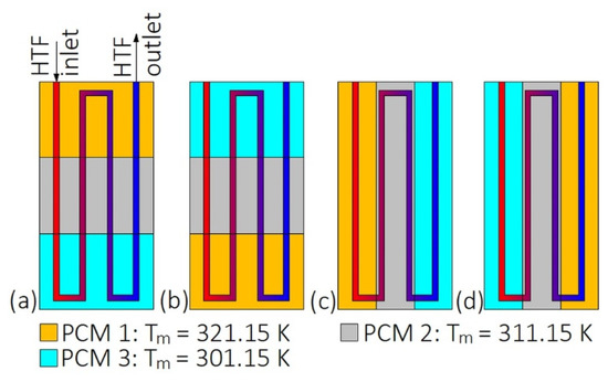
Figure 1.
Heat exchanger with multiples phase change materials (PCMs) [46]: (a) Horizontal descending arrangement; (b) horizontal descending arrangement; (c) vertical descending arrangement; (d) vertical ascending arrangement. Tm—melting temperature.
Regarding the melting temperatures of cascaded PCMs, Domanski and Fellah [47] concluded that to achieve the best exergy efficiency of a multiple PCMs LHTES system, the melting temperatures of the first and the last PCMs should be close to the HTF inlet temperature and ambient temperature, respectively. Furthermore, Gong and Mujumdar [48] and Xu et al. [49] reported that the melting temperatures of PCMs should change in a geometrical progression, whereas Tao et al. [50] presented mathematical formulas based on the entransy theory, allowing for the determination of the optimal melting temperatures of PCMs in the two-stage LHTES unit (for detailed information about the entransy theory, readers are referred to [51]). The studies on the multiple PCMs in LHTES systems are collected in Table 1.

Table 1.
Research on heat transfer enhancement with multiple PCMs.
One of the advantages of using multiple PCMs is that they possess better thermal performance in terms of heat transfer rate [43], thermal efficiency [52], exergy efficiency [53,54], and phase change time [55] than LHTES units with only one PCM. For example, Cheng and Zhai [56] found that the solidification time of the cascaded LHTES unit consisting of three PCMs decreased by 25% compared to the non-cascaded LHTES.
The thermal performance of cascaded LHTES systems increases with an increasing number of PCMs, but as a result, the complexity and operating costs of the system grow [52]. Therefore, Aldoss and Rahman [43] concluded that using more than three PCMs is not recommended from a practical and economical point of view. As can be seen from Table 1, cascaded LHTES systems with three PCMs are most commonly investigated among the literature reviewed. Furthermore, in most cases, the mass or volume ratio of the PCMs was 1:1:1 (see Table 1). However, changing the PCMs mass or volume ratio can also impact the thermal performance of cascaded LHTES. Li et al. [57] reported that when the volume ratio of PCMs was changed from 1:1:1 to 2.5:4.0:5.5, each PCM melted at the same time. A similar finding was achieved by Wang et al. [41], who found that as the mass ratio of PCMs was 16:6:8, the PCMs melted simultaneously. Additionally, the melting time of PCMs with mass ratio 16:6:8 decreased by 11% and 26%, compared to multiple PCMs with equal mass ratio and to a single PCM, respectively. Li et al. [58] reported that the solidification time of multiple PCMs with volume ratio 1:2:3 was the shortest among the volume ratios investigated, and decreased by 9% compared to the single PCM solidification time. On the other hand, Ahmed et al. [59] found that the solidification time of multiple PCMs was longer by 27% than the solidification time of a single PCM. A possible explanation of such discrepancies could be the differences in the thermophysical properties of different PCMs used by the two research groups.
3. Types of Heat Exchangers Used in LHTES Systems
The researches on thermal performances of different types of heat exchangers are described in Section 3.1, Section 3.2, Section 3.3, Section 3.4, Section 3.5, Section 3.6, Section 3.7 and Section 3.8, while Table 2, Table 3, Table 4, Table 5, Table 6, Table 7, Table 8 and Table 9 summarize the reviewed literature on the HXs.
Table 2.
Research on the plate heat exchangers.
Table 3.
Research on the helical-coil heat exchangers.
Table 4.
Research on the double-tube heat exchangers.
Table 5.
Research on the triple-tube heat exchangers.
Table 6.
Research on the multi-tube heat exchangers.
Table 7.
Research on the heat exchangers with encapsulated PCMs.
Table 8.
Research on the enclosure-type heat exchangers.
Table 9.
Research on the other types of heat exchangers.
3.1. Plate Heat Exchangers
Plate heat exchangers consist of an enclosure with slabs (plates) inside. The slabs are filled with a PCM, and between each slab, there is a gap through which an HTF flows. The HTF might also flow through the slabs and, therefore, the PCM is placed directly in the enclosure. Regardless of the placement of the PCM and the HTF, the heat transfer surface area between them is one of the most important factors affecting the thermal performance of the HX. Hence, some researchers proposed to use zigzag [41,45], and trapezoidal [63] slabs (Figure 2b,c) with improved heat transfer surface area. However, the thermal performance of HXs with such plates was not compared to the thermal performance of the HX with straight plates. To increase the heat transfer surface area, Johnson et al. [12] added zigzag structures into the PCM. As a result, the solidification time of the PCM decreased from 2.75 to 1.55 h when the zigzag structures were added to the HX.
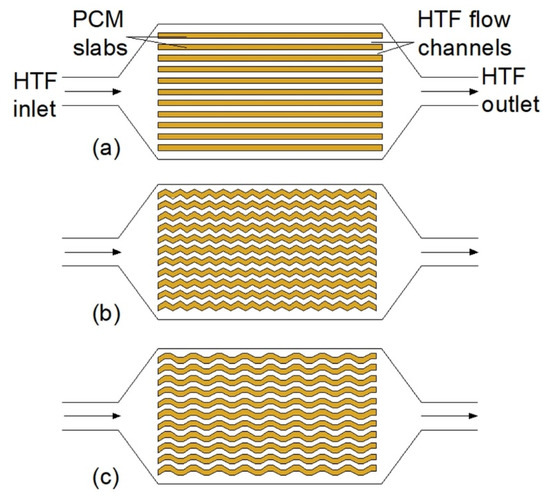
Figure 2.
Plate heat exchangers: (a) With flat PCM slabs, (b) with zigzag PCM slabs [41,45], (c) with trapezoidal PCM slabs [63].
Compared to the other types of HXs, plate HXs could obtain high effectiveness, up to 0.82 [40]. Moreover, Gürel [63] found that the melting time of a PCM in plate HX decreased by 75%, compared to the double-tube heat exchanger (DTHX) with the same volume of the PCM. On the other hand, Medrano et al. [23], who examined thermal performances of DTHXs, compact HX, and plate HX, concluded that plate HXs are not appropriate for using in LHTES, because of the low ratio of PCM heat capacity over empty HX heat capacity.
The influence of geometrical parameters of plate HXs on its thermal behavior was investigated by several researchers. Saeed et al. [40] found that using 20 plates with HTF instead of 10 resulted in a shorter melting time (the researchers did not report the exact value of improvement), but the volume occupied by 20 plates was higher by 1.3%, compared to 10 plates. Gürel [63] and Hoseinzadeh et al. [64] also concluded that when the mass of PCM was constant, increasing the number of plates with HTF led to a shorter melting time, but the researchers did not provide the exact values of the time reduction. However, when the number of plates increased, the total volume of the HX also increased, which is disadvantageous [64]. On the other hand, Liu et al. [65] investigated the influence of PCM slabs’ dimensions on the thermal performance of the HX. They concluded that the dimensions of the slabs had a negligibly small influence on the melting time of PCM.
3.2. Helical-Coil Heat Exchangers
The second type of heat exchangers used in LHTES systems is helical-coil HXs (HCHXs). They consist of a cylindrical insulated tank (shell) filled with PCM, and a coil through which an HTF flows, as shown in Figure 3.
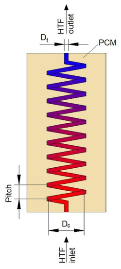
Figure 3.
Plate heat exchanger with upward heat transfer fluid (HTF) flow. Dc—coil diameter, Dt—tube diameter.
Dimensions and geometry are one of the parameters that influence the thermal performance of HCHXs. Appropriate geometry of the HCHX might considerably augment the heat transfer rate and, thus, reduce the phase change time of a PCM in the heat exchanger. To reduce the melting time of PCM in horizontally oriented HX, it is advisable to increase the helical-coil diameter, which reinforces the convective heat transfer because the HTF flows through a lower part of the HX [69]. Rahimi et al. in their two works [69,70] examined the HCHX with helical-coil diameters of 90, 70, and 50 mm, but with the same heat transfer surface area. It was found that as the helical-coil diameter increased from 50 to 90 mm, the melting time of PCM decreased by 72.6%. However, no significant difference in the melting time was observed when the helical-coil diameter was changed from 70 to 90 mm. A similar finding was reported by Ahmadi et al. [71] who studied the performance of the HCHX under nine different geometrical configurations with constant PCM volume. The melting time of PCM decreased by 49.2% and 71.4% when the coil diameter increased from 50 to 60 mm, and 50 to 70 mm, respectively. Additionally, when the coil diameter was 50 mm, the melting time decreased with an increasing tube diameter from 8 to 16 mm, whereas, when the coil diameter was 60 and 70 mm, the melting time decreased with a decreasing tube diameter, which might be explained as follows. On the one hand, for a constant coil diameter, the heat transfer surface area increased as the tube diameter decreased. Hence, it seems obvious that the melting time should decrease with a decreasing tube diameter. On the other hand, for the coil diameter of 50 mm and the tube diameter of 8 mm, there was a large space between the lowest part of the coil and the shell; thus, the melting of PCM in the bottom part of the HX was prolonged. However, when the tube diameter increased, the space between the lowest part of the coil and the shell decreased, which reduced the melting time of the PCM in the bottom part of the HX.
Chen et al. [37] concluded that in the case of a horizontal helical-coil HX, the optimal value of the helical-coil radius-to-shell radius ratio should be kept between 0.53 and 0.64. These values provided the shortest melting time of the PCM and the best temperature distribution in the HX.
Some of the researchers proposed new types of coil shape to enhance heat transfer. Ardahaie et al. [72] investigated nine different geometrical configurations of the proposed novel coil shape (Figure 4), but the mass of PCM and the heat transfer surface area was kept constant in all cases. The melting time of PCM decreased as the number of flat spiral tubes increased. Moreover, when the HX was oriented vertically and the spacing between the flat spiral tubes in the bottom part of the HX was reduced, the melting time decreased by 30%, compared to the horizontal HX. However, when the spacing between the flat spiral tubes was equal, no significant difference in the melting time of PCM in horizontal and vertical HX was observed, whereas the melting time was the longest when the HX was inclined at 45°. Because PCM melting is a natural convection-dominant process, Mahdi et al. [73] proposed to use a conical-shape coil that had a large diameter at the bottom of the HX and small diameter at the top. The melting time of the PCM in the conical-shape coil HX decreased by 22% compared to the traditional helical-coil HX, while the heat transfer surface area and the volume occupied by the PCM were the same in the two HXs.
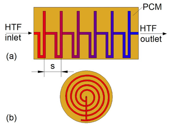
Figure 4.
The new type of helical-coil heat exchanger (HX): (a) Side view, (b) front view [72]. s—spacing between flat spiral tubes.
In the case of vertically oriented HCHXs, HTF might flow from the bottom to the top or in the opposite direction. The influence of flow direction on the thermal performance of the HX was investigated by Saydam et al. [18] who concluded that the HTF flow direction influenced neither melting nor solidification time of the PCM.
3.3. Double-Tube Heat Exchangers
Double-tube heat exchangers (DTHXs) consist of two usually concentric tubes, which create two regions: The inner tube area, and the annulus area between the inner and the outer tube. Depending on which region a PCM and an HTF are located, there are two possible DTHX models: Pipe model and tube model [77,78], which are shown in Figure 5. Han et al. [78] showed that the melting time of the PCM in the horizontal cylinder model DTHX was lower by 23.5% compared to the pipe model if the PCM mass and heat transfer surface area was equal in each case. A similar result was reported by Mahdi et al. [79], who found that the melting time of the PCM was 43 and 18 min for pipe and cylinder model, respectively. However, solidification time was shorter in the pipe model (51 min) compared to the cylinder model (90 min). Therefore, the complete melting–solidification cycle was shorter for pipe than the cylinder model. In contrast, Chen et al. [77] reported that the full melting–solidification cycle was shorter for the cylinder model DTHX (12,900 s) than for the pipe model (18,000 s). However, the volume occupied by the PCM accounted for 70% of the total DTHX volume; thus, the heat transfer surface area of cylinder model DTHX was larger than the pipe model. Nevertheless, based on Table 4, it can be concluded that the pipe model DTHX has been investigated more often among the literature reviewed than the cylinder model.

Figure 5.
Vertical double-tube HX: (a) Cylinder model with downward HTF flow direction, (b) pipe model with upward HTF flow direction.
An inclination angle of the DTHX impacts natural convection during melting [80], which might affect the thermal performance of the HX, but the results of research in this area are inconsistent. Han et al. [78] concluded that there was almost no difference in melting time when cylinder model DTHX was placed horizontally or vertically. Moreover, it was found that the upward HTF flow direction ensured the shortest melting time in the cylinder and pipe model DTHX. On the other hand, Mahdi et al. [81] found that the melting time of PCM in horizontal DTHX was reduced by 28% compared to vertical DTHX. Mehta et al. [82] showed that the melting time of a PCM in vertical and horizontal DTHXs was 480 and 460 min, respectively, which gives a difference of less than 5%. However, in their second work [83] it was concluded that the melting time of the PCM was shorter for vertical than for horizontal DTHX, but the shortest melting time was achieved when the inclination angle was 45°. A similar result was obtained by Al Siyabi et al. [80], who found that when the inclination angle was 45°, the melting time was reduced by 13% compared to horizontal DTHX. On the other hand, the inclination angle has an insignificant impact on the solidification process, because of its conduction-dominated nature [15,83].
Another factor influencing the thermal performance of a DTHX is its geometry. To promote natural convection, Kadivar et al. [16] designed DTHX with a non-concentric inner tube (Figure 6). Such modification resulted in a reduced melting time of PCM up to 7.1 times compared to concentric DTHX. However, the solidification time was longer in non-concentric DTHX, and consequently, the complete melting-solidification cycle was the shortest in concentric DTHX. However, Li et al. [84] in their research took into account the volume expansion of the PCM during melting and consequently an air region at the top of the HX when the PCM was in the solid state. The results showed that lowering the inner tube did not influence the melting time of the PCM when the air region was taken into account.
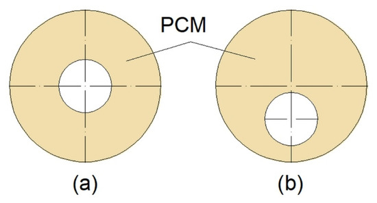
Figure 6.
Cross-section of: (a) Concentric; (b) non-concentric Double-Tube Heat Exchanger (DTHX) [16].
The natural convection can be also augmented by changing the shape of the inner or outer tube of XH. Therefore, Chen et al. [77] examined the thermal performance of a cylinder model DTHX with three shapes of inner tubes: Circular, horizontal ellipse, and vertical ellipse, as shown in Figure 7. The mass of PCM was equal in each case; however, the authors did not specify if the outer tubes of the heat exchangers were also changed to an ellipse shape; thus the outer tubes of the HXs are marked with dashed lines in Figure 7. Compared to the HX with the circular inner tube (Figure 7a), the greatest reduction, by 11.6%, of complete melting–solidification time was obtained for the HX with the horizontal ellipse inner tube (Figure 7b). Seddegh et al. [85] compared the thermal performance of two DTHXs: Cylindrical and conical. Both HXs were oriented vertically and the same mass of PCM was placed in each HX. The difference between the HXs was that the outer tube diameter of the cylindrical HX was kept constant, while the outer tube diameter of the conical HX was small at the bottom and large at the top of the HX. The melting process in the conical DTHX was about 12% faster than in the cylindrical DTHX. The same shape of the DTHX was proposed by Sodhi et al. [86]; however, the HXs (cylindrical and conical) were oriented horizontally, and the outer tube diameter of the conical HX was decreasing along with the HTF flow. The melting and solidification time of the PCM in the conical DTHX decreased by 17% and 28%, respectively, compared to the cylindrical DTHX. Such an improvement was a result of a better PCM distribution, i.e., the volume of PCM decreased with the HTF flow path and decreasing temperature difference between the HTF and PCM. Another type of heat exchanger–double-tube helical-coil HX, which is shown in Figure 8, was proposed by Mahdi et al. [81]. The melting time of a PCM in the proposed HX was reduced by about 25.7% and 60% compared to horizontal and vertical straight DTHX, respectively.
Figure 7.
Cross-sections of the cylinder model DTHX: (a) Circular inner tube, (b) horizontal ellipse inner tube, (c) vertical ellipse inner tube [77].
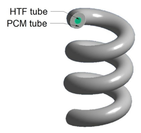
Figure 8.
The double-tube helical-coil HX [81].
One of the most common heat transfer enhancement methods is the application of fins. In the case of DTHXs, two types of fins can be used: Longitudinal and circular (radial), which are shown in Figure 9. Agyenim et al. [87] compared the thermal performance of the DTHX without fins, with longitudinal fins, and with circular fins. They concluded that using longitudinal fins in horizontally oriented HX is more advisable than using circular fins because after 8 h of charging the PCM melted completely only in the HX with longitudinal fins. However, Scharinger–Urschitz et al. [88] reported that when the longitudinal and circular fins were used simultaneously, the melting was faster by 32% compared to HX with only longitudinal fins. Nevertheless, the application of longitudinal fins can reduce the melting time of PCM by 50% compared to the non-finned HX [89]. A possible explanation for better performance of longitudinal fins than circular fins could be that the circular fins augment the heat transfer only in the regions near the fins and in the radial direction, whereas, the longitudinal fins augment the heat transfer in both radial and axial directions.
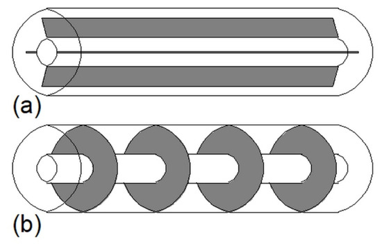
Figure 9.
DTHX with: (a) Longitudinal fins; (b) circular (radial) fins.
Generally, the melting and/or solidification time of a PCM decreases with an increasing number and length of fins, which was reported by Deng et al. [90,91] and Nie et al. [92]. Deng et al. [90] found that when the number of fins increased from 2 to 10, the melting time of PCM decreased by 63.3%. In their second work, Deng et al. [91] increased the dimensionless length of fins from 0.5 to 0.95 (dimensionless length of fins was defined as the ratio of the fin’s length to the difference between the radius of the outer and inner tubes), the melting time of PCM decreased by 45.3%. Nie et al. [92] showed that when the number of fins increased from 2 to 10, the time of the complete melting–solidification was reduced by 67.6%, whereas, when the dimensionless fins length (defined as the ratio of the fin length to the difference between the radius of the outer and inner tube) increased from 0.5 to 0.95, the melting-solidification time decreased by 50.6%. However, it should be noted that as the number or length of fins increases, the share of sensible heat stored in fins is growing, but less PCM can be placed in an HX. As a result, the overall heat storage capacity of an HX might decrease [93]. Therefore, Pu et al. [94] reported that when the number and length of fins are changed so that their volume is constant, then there exists an optimal value of number and length of fins to obtain the shortest melting time. Additionally, Karami and Kamkari [29] proposed to use perforated circular fins, i.e., fins with cut-out holes. The weight of HX with perforated fins was 16% less compared to HX with solid fins. Moreover, perforated fins had less impact on the weakening of natural convection than solid fins.
As mentioned in Section 2, melting is a convection-dominated process, and PCM begins to melt at the top of an HX. Therefore, to reduce the melting time, fins should be gathered in the lower part of an HX rather than in the upper part [90,91,92,94]. When circular fins are applied into a vertically oriented HX, it is advisable to reduce the distance between adjacent fins in arithmetic progression from top to bottom, which can reduce PCM melting time by 49.9% [94]. The influence of the fins’ arrangement (see Figure 10) on the melting time of PCM in horizontal DTHX was investigated by Deng et al. [91]. They found that the melting time of PCM decreased by 59.2%, 39.6%, 56.3%, and 57.9% for the HX with bottom fins (Figure 10a), upper fins (Figure 10b), straight fins (Figure 10c), and angled fins (Figure 10d), respectively, compared to the non-finned HX. Therefore, it was concluded that the bottom fins arrangement was the most advantageous. On the other hand, Nie et al. [92] found that although locating fins in the lower part of a DTHX reduces the melting time, it slows down the solidification process. Therefore, to achieve complete melting–solidification time possibly short, the fins should be distributed equally around the tube circumference.

Figure 10.
DTHX with: (a) Bottom fins, (b) upper fins, (c) straight fins, (d) angled fins [91].
Besides the arrangement of fins, numerous researchers investigated the fins of various shapes. Aly et al. [95] found that when the straight longitudinal fins were replaced by corrugated fins, the solidification time of PCM decreased by 38%. Furthermore, Scharinger–Urschitz et al. [88], Zhang et al. [96], and Luo and Liao [97] proposed using fractal Y-shaped (tree-shaped, dendritic) fins. Zhang et al. [96] found that using Y-shaped fins resulted in reduced melting and solidification time by 4.4% and 66.2%, respectively, compared to straight fins. As can be seen, the solidification time was reduced much more than the melting time, which might have been caused by the fact that Y-shaped fins could suppress natural convection, while due to enlarged heat transfer surface area, the fins accelerated the conduction-dominant solidification.
The other shape of fins, i.e., fins based on the snowflake crystal structure, was used by Sheikholeslami et al. [98]. They reported that when the straight fins and snowflake fins were used, the solidification was 4.5 and 7.8 times faster, respectively, compared to the non-finned HX. Nevertheless, although the non-straight fins can augment the phase change time significantly, it should be noted that the production process of such fins is more complicated and the production costs of non-straight fins are higher than that of the straight fins [99].
The other possibility of heat transfer enhancement is the use of heat pipes, which was investigated by Mahdavi et al. [100]. When the number of heat pipes was one, two, three, and four, the melting time was reduced by 40%, 61.2%, 76%, and 83%, respectively, and the solidification time decreased by 43%, 77%, 88%, and 96%, respectively, compared to the DTHX without heat pipes. However, as the number of heat pipes increased to four, the stored heat decreased by 14%, because of the decreased amount of PCM in the HX.
3.4. Triple-Tube Heat Exchangers
Triple- or triplex-tube heat exchangers (TTHXs) are made of three tubes which creates three separate areas. The inner tube area and the area between the middle and the outer tube might be used as an HTF flow channel; then, the region between the inner and the middle tube is aimed to store a PCM. However, the opposite configuration is also possible. Independently from the HTF and PCM location, TTHXs possess a larger heat transfer surface area than DTHXs [103,104].
One of the factors that affect the thermal performance of a TTHX is its dimensions and shape of tubes. Gorzin et al. [105] investigated the thermal performance of the TTHX with different radiuses of the tubes, but with a constant mass of the PCM. The PCM was located in the inner tube and the region between the middle and the outer tube. It was found that the optimal radiuses of the inner, middle and outer tubes were 20.2, 54, and 67.4 mm, respectively, and the solidification time of the PCM in such an HX’s configuration decreased by 62% compared to the cylinder model DTHX. Chen et al. [77] examined the TTHX with an elliptical inner and middle tube, as shown in Figure 11a,b, but they did not specify if the shape of the outer tube was also changed from circular to elliptical; thus, the outer tubes of the HXs are marked with dashed lines in Figure 11. Nevertheless, the shortest melting and solidification time was achieved for HX with the horizontal ellipse inner tube (Figure 11a). In this case, i.e., Figure 11a, the melting and solidification time was reduced by 40.9% and 59.2%, respectively, compared to the circular cylinder model DTHX.
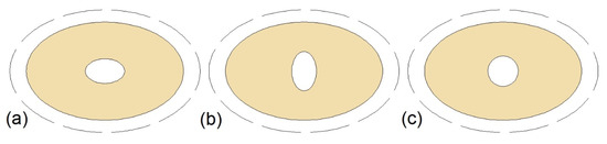
Figure 11.
Triple- or triplex-tube heat exchangers (TTHXs) with: (a) Horizontal ellipse inner tube; (b) vertical ellipse inner tube; (c) circular inner tube [77].
To increase the heat transfer surface area, Shahsavar et al. [106] designed the TTHX with sinusoidal wavy inner and middle tubes. The melting and solidification time of the PCM in the designed TTHX decreased by 50% and 48%, respectively, compared to the TTHX with straight tubes.
Although changing the dimensions or shape of a TTHX can significantly improve its thermal performance, the application of fins is the most commonly used technique for heat transfer enhancement. Mahdi and Nsofor in their two works [107,108] reported that using straight fins can reduce the melting and solidification time up to 59% and 55%, respectively, compared to non-finned HX. Although straight longitudinal fins are usually used, the application of triangular [109,110] and V-shaped [111] fins can be also found. Alizaedh et al. [111] found that the solidification time of PCM in the V-shaped-finned HX was 1.94 times faster than the solidification time in the non-finned HX. Independently of the shape of fins, phase change time can be reduced more by increasing the number of fins and/or increasing their length. Abdulateef et al. [109] found that when the number of fins increased from 5 to 8 the melting and solidification time of the PCM decreased by 39.6% and 46.5%, respectively. Furthermore, when the length of fins was increased by 27%, the melting time was reduced by 21%. Mat et al. [112] investigated the thermal performance of finned HX. The investigated lengths of fins were 10, 20, 30, and 42 mm. The results showed that the maximum reduction of melting time, by 43.3% compared to non-finned HX, was achieved for the HX with fins of length 42 mm. Al-Abidi et al. [113] reported that when the length of fins was 10 and 42 mm, the melting time of the PCM was reduced by 26.1% and 56.6% compared to the non-finned HX. Furthermore, the greatest reduction of the melting time, by 65.3% compared to the non-finned HX, was achieved when the length of the fins was equal to the distance between the inner and the middle tube. Mahdi et al. [114] found that for constant volume of fins, changing and optimizing the fin configuration might reduce the melting time of PCM by 36%, compared to the HX with non-optimized fins arrangement.
On the other hand, changing the thickness of the fins does not influence much on the phase change time of the PCM [111,113]. Moreover, it was concluded that to obtain the shortest phase change time, long and thin fins are preferred instead of short and thick [107,108]. Nevertheless, it should be noted that by increasing the number of fins or their length, the volume which can be occupied by the PCM decreases. As a result, HX’s heat capacity can also decrease. Therefore, instead of changing the dimensions of the fins, it was proposed to change their arrangement. Mat et al. [112] investigated the melting time of the PCM in the TTHX with three configurations of fins. Firstly, fins were attached to the inner tube (internal fins), then to the middle tube (external fins), and finally to both inner and middle tubes (internal-external fins), as shown in Figure 12. It was found that the internal–external fins provided the shortest melting time, which was reduced by 56.7% compared to the non-finned HX. A similar finding was achieved by Zarei et al. [115] who reported that using the internal–external fins in the TTHX is the most advantageous and can reduce the solidification time of the PCM by 42% compared to the non-finned HX.
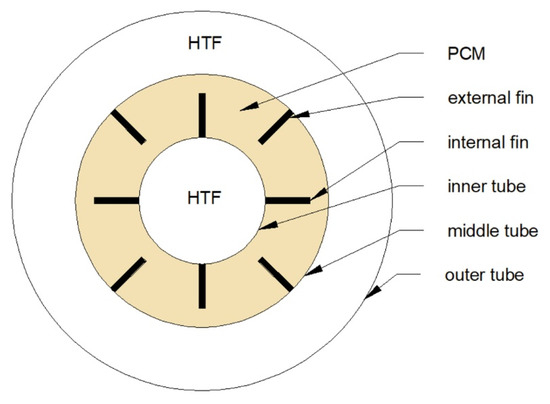
Figure 12.
Cross-section of a TTHX with a possible arrangement of longitudinal fins [112].
The internal–external fins were used also by Eslamnezhad et al. [116], who additionally changed the inclination angle of the fins. This modification reduced the melting time by 12.6% compared to the HX with the fins mounted perpendicularly to the pipes (base case). Moreover, when the inner tube was moved down by 5.4 mm, the melting time decreased by 17.9% compared to the base case. Mahdi et al. [114] found that to obtain the shortest melting time, long and short fins should be located in the lower and upper parts of the HX, respectively. That configuration enhanced the heat transfer in the lower part of the HX and did not suppress the natural convection in the upper part.
Another possibility of increasing a heat transfer surface area is the use of metal foam. Mahdi and Nsofor [117,118] found that using copper foam can decrease the melting and solidification time by 88.8% and 95.7%, respectively. Moreover, the phase change time decreased with decreasing porosity of the copper foam.
3.5. Multi-Tube Heat Exchangers
Multi-tube heat exchangers (MTHXs) consist of an outer tube (shell) and two or more inner tubes, which ensures a large heat transfer surface area. Therefore, increasing the number of tubes in MTHXs, while simultaneously keeping the mass of the PCM constant, reduces the melting and solidification time, which was reported by Esapour et al. [17], Pourakabar and Rabienataj Darzi [21], Kousha et al. [119], and Sodhi et al. [120]. Kousha et al. [119] reported that when the number of tubes increased from 1 to 4, the melting and solidification time decreased by 43% and 50%, respectively. Sodhi et al. [120] found that the melting and solidification time was reduced by 20% and 48%, respectively, when the number of tubes increased from 13 to 25.
Although increasing the number of tubes enhances the heat transfer, an appropriate arrangement of tubes can also intensify the heat transfer. To shorten a phase change time of the PCM, the tubes should be gathered in the lower part of an MTHX [121]. Esapour et al. [17] investigated the thermal performance of the MTHX with three inner tubes, which were positioned in such a way that their centers formed a triangle. In one case, the base of the triangle was located at the bottom part of the MTHX, whereas in the second case, at the top. The melting time of the PCM in the first case was shorter by 15% compared to the second case, which confirms that the bottom-arrangement of tubes is favorable to shorten the melting time. However, the solidification time was reduced by 9% in the second case, compared to the first case.
Pourakabar and Rabienataj Darzi [21] studied the thermal performance of the MTHXs with cross-sections as shown in Figure 13 and with a constant mass of the PCM. The maximum reduction of the melting time, by 74% compared to DTHX, was achieved for the case Figure 13b. However, the shortest solidification and complete melting–solidification process were reported for the case Figure 13d, and these processes were shortened by 42% and 52%, respectively, compared to the DTHX. Additionally, the application of elliptical shells (cases Figure 13e–h) resulted in reduced melting time compared to the DTHX, but it had a minor effect on the solidification time. Furthermore, it was concluded that the influence of the tubes’ arrangement on the thermal performance decreases with an increasing number of tubes.
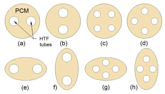
Figure 13.
Cross-section of the TTHX: (a) Two horizontal inner tubes; (b) two vertical inner tubes; (c) four inner tubes; (d) four inner tubes with the modified arrangement; (e) horizontal elliptical outer tube and two inner tubes; (f) vertical elliptical outer tube and two inner tubes; (g) horizontal elliptical outer tube and four inner tubes; (h) vertical elliptical outer tube and four inner tubes [21].
The other possibilities of heat transfer enhancement in MTHXs are the application of fins or metal foams. Kuboth et al. [122] investigated the influence of circular fin arrangement on the solidification time of PCM in the vertical MTHX. The shortest solidification time was obtained when the distance between the adjacent fins increased linearly with the height of the HX. Bhagat et al. [123] reported that to reduce the melting time of the PCM, a greater number of thin fins is better than a smaller number of thick fins.
The copper foam was used by Esapour et al. [17]. They found that the melting and solidification time of PCM was reduced by 56% and 75%, respectively, when the PCM/copper foam was used instead of pure PCM. Additionally, it was concluded that the phase change time decreased with decreasing porosity of the foam; however, the effect was not significant. A similar finding was reported by Pourakabar and Rabienataj Darzi [21] who found the melting and solidification time of the PCM decreased by 92% and 94%, respectively, when the copper foam was applied.
3.6. Heat Exchangers with Encapsulated PCMs
One of the purposes of modifying heat exchangers’ constructions is to increase the heat transfer surface area. This can be achieved by using spherical capsules filled with PCM. The capsules are usually placed in a tank and a flowing HTF exchanges heat with each capsule. This solution can be applied in traditional water thermal energy storage tanks and it can improve their heat storage capacity by 30% [126].
The PCM capsules’ diameter is one of the parameters that affects the thermal performance of heat exchangers with encapsulated PCMs. As the capsules’ diameter decreases, their number and the heat transfer surface area increases [127,128]. Consequently, the melting and solidification time of the PCM decreases, which was concluded by Bellan et al. [22], Wu et al. [127], Karthikeyan et al. [128], and Li et al. [129]. Li et al. [129] reported that due to the large heat transfer surface area, the charging and discharging rates of HX with PCM capsules was 2.1 times and 3.2 times higher, respectively, than the charging and discharging rates of the shell and tube HX. Karthikeyan et al. [128] found that as the capsules’ diameter decreased from 100 to 60 mm, the number of capsules and the heat transfer surface area increased from 87 to 420 and from 2.73 to 4.75 m2, respectively. Therefore, the melting time was reduced by 35.6%. However, Wu et al. [127] also reduced the capsules’ diameter from 100 to 60 mm and the reduction of melting and solidification time was only 6.4% and 8%, respectively. A possible explanation of the differences in results achieved by those two research groups, i.e., Karthikeyan et al. [128] and Wu et al. [127], could be as follows. The decrease in capsules’ diameter results not only in an enlarged heat transfer surface area but also in a decreased porosity of a packed bed. The porosity of the packed bed can be defined as the ratio of the volume of voids to the total volume of a packed bed [126,129]. Thus, as the porosity decreases, a larger amount of PCM is in the heat exchanger, which might extend the phase change time, which was reported by Wu et al. [36], who investigated the influence of packed bed porosity on the PCM’s solidification time. It was concluded that as the porosity decreased from 0.55 to 0.35, the solidification time increased, but the authors did not report the exact value of the solidification time extension. A similar finding was reported by Raul et al. [130], who investigated the phase change time of PCM packed beds with porosities 0.6, 0.7, 0.8, and 0.9. It was found that when the porosity decreased from 0.9 to 0.6, the melting and solidification time increased by 73% and 9%, respectively. Additionally, the capsules’ diameter also affects the mechanism of heat transfer inside the capsules, which was reported by Bellan et al. [22]. They concluded that the natural convection in small capsules was insignificant; thus, the difference between the melting and solidification time was slight. But, as the diameter increased, the convective heat transfer was augmented and an increasing difference between the melting and solidification time was observed.
3.7. Enclosure-Type Heat Exchangers
A common feature of the heat exchangers described in Section 3.1, Section 3.2, Section 3.3, Section 3.4, Section 3.5 and Section 3.6 was that the heat source was an HTF flowing through the tubes or plates. However, if for some reason embedding the HTF tubes or plates in the PCM is not possible, the heat can be supplied to the PCM through the sides and/or bottom walls of the enclosure, which in this case will be acting as heat sources. This type of heat exchanger is often used for cooling electronic devices [132] or photovoltaic panels [133].
The first parameter that influences the thermal performance of such heat exchangers is its inclination angle and the location of a heat source. Ren et al. [134] found that when 100% of PCM was melted in the square enclosure heated from the bottom, only 84.63% of the PCM was melted in the side-heated enclosure. To achieve possibly short melting time in rectangular enclosures, it is recommended to set the enclosure horizontally, i.e., the long walls should be oriented horizontally, and the heat source should be located on the bottom wall, which was reported by Kamkari and Amlashi [135] who found that when the inclination angle of the rectangular enclosure was changed from 90 (vertical) to 45, and 0° (horizontal), the melting time of the PCM decreased by 37%, and 52%, respectively. Kamkari and Groulx [136] additionally concluded that decreasing the inclination angle of the enclosure was more beneficial than adding the fins to the vertical enclosure. A similar finding was reported by Karami and Kamkari [137], who concluded that the melting time of the PCM in the vertical non-finned enclosure was shorter than the melting time in the 1-fin and 3-fin enclosures inclined at more than 90°. Nevertheless, the melting time of PCM in finned enclosures is shorter than in non-finned enclosures. For example, Abdi et al. [138] reported that the melting time of PCM in the horizontal enclosure with five fins was reduced by 68% compared to the non-finned enclosure. However, the amount of PCM decreased by 12%, and the heat capacity was reduced by 6%.
Shape and dimensions of fins are important parameters that affect the thermal performance of the enclosure-type HXs. Ren et al. [134] replaced one rectangle fin with two triangle fins with the same volume to keep the PCM mass constant. That replacement decreased the melting time by 6.87%. It was also reported that long and narrow triangle fins ensured a faster melting process than short and wide triangle fins. Additionally, the melting time was reduced by 3.86% when the equal-length fins were replaced with the unequal-length fins, i.e., the long and short fins were located in the bottom and upper parts of the enclosure, respectively. The short fin enabled the growth of natural convection, while the long fin ensured a greater heat transfer area, which improved the melting rate. A similar finding was reported by Joshi and Rathod [26], who examined the influence of fins’ length and their arrangement on the performance of the vertical enclosure. In the base case, three fins with equal lengths were distributed evenly at the enclosure. Then, the lengths of the two fins were reduced by 75%, and 50% and the fins were moved by 12 mm down, as shown in Figure 14. Such modification resulted in improved melted fraction by 6.34% and enclosure’s heat capacity increased by 4.38% compared to the base case.
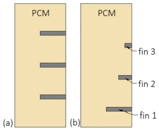
Figure 14.
The length and arrangement of fins: (a) Equal-length fins; (b) fins moved down, the length of fin 2 and 3 reduced by 50% and 75%, respectively, compared to fin 1 [26].
Another possibility to improve the heat transfer and do not suppress the natural convection at the upper part of the enclosure is to change the inclination angle of fins, which was investigated by Ji et al. [139]. The fins were inclined upward (Figure 15a) at +15, and +30°, as well as downward (Figure 15b) at −15, and −30°. The shortest melting time of PCM was achieved for fins inclined at −15°. For that inclination, the saved melting time, defined as the difference between the melting time in the non-finned and finned enclosure, increased by 23.8% compared to fins inclined at 0°.
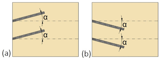
Figure 15.
The inclination angle α of fins: (a) Upward; (b) downward [139].
Although fins can considerably reduce the phase change time of PCM, heat pipes can give even better results. Ladekar et al. [140] found that the melting and solidification time of PCM decreased by 45% and 40%, respectively when the copper fins were replaced by heat pipes. Among the reviewed papers, the greatest reduction of melting time, by 94%, after the addition of heat pipe to the non-enhanced enclosure was achieved by Motahar and Khodabandeh [141], whereas Yang et al. [30] reported the smallest melting time reduction, by 11.26%. Such discrepancies could be a result of different PCMs and heat pipes used, as well as the different operating conditions during the investigations. Nevertheless, heat sinks with PCMs and heat pipes found an application in thermal management of batteries—the heat sinks support maintaining a constant batteries’ temperature [142,143].
3.8. Other Types of Heat Exchangers
Construction of some heat exchangers is specific, and therefore it is difficult to assign them to the categories described in Section 3.1, Section 3.2, Section 3.3, Section 3.4, Section 3.5, Section 3.6 and Section 3.7. These other heat exchangers can be made of a cylindrical [34,148,149,150,151,152,153] or rectangular cuboid enclosure [25,62,154,155,156,157] filled with PCM. Heat is transferred between PCM and HTF through pipes, however, in contrast to the MTHXs, the HTF flows successively through each subsequent pipe, as shown in Figure 16. Nevertheless, other constructions are also possible. For example, Lin et al. [148,149] designed and investigated the thermal performance of the heat exchanger with two HTF flow channels as shown in Figure 17. That design allowed for the use of two different HTFs and extended operational flexibility of the HX. Furthermore, the heat transfer rate was augmented by increasing the number of baffles which enhanced turbulence of HTF; however, they increased the HTF pressure drop. Therefore, nine baffles were chosen as the optimal number.
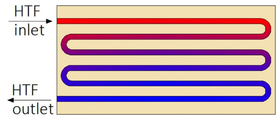
Figure 16.
An example of the other type of heat exchanger.
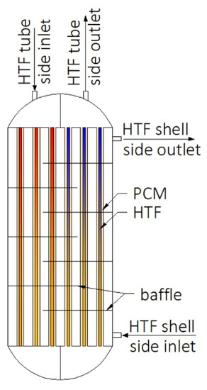
Figure 17.
Heat exchanger designed by Lin et al. [148,149].
Similar to the case of MTHXs, in the other types of HXs melting time of PCM decreases with an increasing number of HTF tubes. Khan et al. [150] found that when the number of HTF tubes increased from 12 to 21, the melting time decreased by 48.5%. However, the mass of PCM also decreased, and it could impact the melting time as well. Ebrahimi et al. [151] also investigated the influence of the number of HTF tubes on the phase change time, but the mass of PCM was kept constant. It was reported that when the number of U-pipes increased from 1 to 2 and from 1 to 3, the melting time was reduced by 17% and 24.1%, respectively. Kurnia et al. [46] found that when the number of tubes increased from 2 to 4, the solidification time of the PCM decreased by 50%.
The main disadvantage of increasing the number of tubes is a large reduction of the HTF temperature along the flow path, which results in the non-uniform phase change process [154]. Therefore, Besagni and Croci [154] proposed to change the flow path of the HTF from the series configuration to the parallel configuration. In the series configuration, all HTF tubes were connected and increasingly colder HTF flowed into each subsequent tube. In the parallel case, the tubes were connected in such a way that three sections were created and the hot HTF flowed into each section. Nevertheless, it was concluded that both heat exchangers performed similarly.
The influence of using fins on the thermal performance of the other types of HXs was investigated by numerous scientists: Talukdar et al. [156], Khan et al. [150], and Pakalka et al. [155]. Talukdar et al. [156] reported that the application of 12 fins reduced the solidification time by about 50%. Khan et al. [150] found that as the length of fins increased three times, the melting time of PCM decreased by 57.32%. Furthermore, when the thickness of the fins was changed from 1 to 5 mm, the melting time decreased by 16.45%. However, such modifications decreased the heat storage capacity of the HX by 1.94% and 5.7%, respectively. Therefore, increasing the length of fins is more effective than increasing their thickness. Pakalka et al. [155] compared the thermal performance of two heat exchangers. In the first heat exchanger, the diameter and thickness of the HTF tubes were 15 and 1.5 mm, respectively, and the number and thickness of fins were 35 and 1.5 mm, respectively. The values of the abovementioned parameters of the second heat exchanger were 12.7, 0.5, 79, and 0.15 mm, respectively. Consequently, the mass of the first and the second heat exchanger was 6.1 and 2.1 kg, respectively. Moreover, the production costs of the first HX were higher than the second one, but the average heat transfer rate and phase change time were almost the same in both cases. Thus, it seems that the heat exchangers should be designed in such a way that their complexity and production costs do not exceed the benefits resulting from their improvements.
Heat transfer enhancement by using heat pipe was investigated by Ebrahimi et al. [151]. The shell of the heat exchanger acted as a heat pipe, as shown in Figure 18, while the HTF flowed through the U-pipes. The application of the heat pipe reduced the melting time by 91%, compared to the HX without the heat pipe. Moreover, it was found that when the inclination angle of the HTF tubes was changed from 0 (Figure 18a) to 90° (Figure 18b), more heat was brought to the bottom part of the HX, and, thus, the melting time decreased by 32%, compared to the HTF tubes inclination angle of 0°.
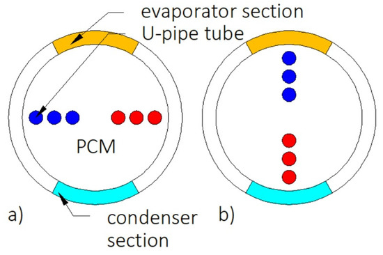
Figure 18.
Cross-section of the heat exchanger with heat–pipe–shell and inclination angle of the HTF U-pipes: (a) 0, (b) 90° [151].
4. Conclusions
Time-consuming PCMs’ phase change in LHTES systems might be shortened by using various methods which include: Increasing the temperature difference between the PCM’s melting point and HTF inlet temperature, increasing the HTF flow rate, using multiple PCMs, and using heat exchangers with appropriate constructions. Based on the cited works, the types of heat exchangers used in LHTES systems and the main possibilities of their improvements to shorten the PCM’s phase change time are summarized in Table 10. Additionally, the value of the greatest possible phase change time reduction achieved among the literature reviewed is given if possible. It should be noted that some improvements significantly shorten the melting time of PCM but increase the solidification time, which is also indicated in Table 10.
Table 10.
Types of heat exchangers for PCMs and the main possibilities of phase change time reduction.
Generally, the phase change time decreases with an increasing HTF flow rate and an increasing temperature difference between the HTF inlet temperature and the PCM melting temperature. However, using PCMs with a much lower melting temperature than the HTF inlet temperature seems to be inadvisable because of large exergy losses, whereas increasing the HTF flow rate results in augmented electricity consumption by a pump. Furthermore, the HTF inlet parameters are usually set in real LHTES systems and cannot be changed. Thus, paying attention to the other methods of enhancing heat transfer, i.e., using multiple PCMs and changing the constructions of heat exchangers, seems more justified.
Using multiple PCMs might shorten the phase change time due to the constant temperature difference between the HTF and PCM’s melting point. To achieve a high exergy efficiency of LHTESs, the temperatures of PCMs should change in geometrical progression and the temperature of the first and the last PCM in order should be close to the HTF inlet temperature and ambient temperature, respectively. Multiple LHTESs with three PCMs were most often investigated among the literature reviewed, and using more than three PCMs is not advisable due to technical and economic difficulties. Although many studies have been conducted on multiple PCMs, the vast majority of them are numerical. Therefore, there is an opportunity to conduct more experimental research on this topic.
Heat exchangers used in LHTES systems were divided into eight types in this paper, and various features of HXs that affect the phase change time of PCMs were discussed.
To shorten the phase change time of PCM in plate heat exchangers, it is recommended to use a large number of thin plates rather than a small number of thick plates. Moreover, the plates can have a trapezoidal or zig-zag cross-sectional shape, which increases the heat transfer surface area.
In the case of horizontally oriented helical-coil HXs, the shortest melting time of PCM can be achieved by using the coil radius-to-shell radius ratio between 0.53 and 0.64. When the HCHX is vertical, the melting time of PCM can be shortened by reducing the distance between the adjacent coils or by increasing and decreasing the coil diameter at the bottom and top parts of the heat exchanger, respectively. Nevertheless, if the coils are distributed evenly in a heat exchanger, the inclination angle of the HCHX does not impact the melting time of PCM significantly.
Double-tube heat exchangers, especially pipe models, were the most often investigated types of heat exchangers among the literature reviewed. If the volume occupied by the PCM is 50% of the total volume of HX, a pipe model DTHX ensures a shorter complete melting/solidification cycle than a cylinder model DTHX. However, if the shortest melting time is required only, then using the cylinder model DTHX is more advisable. The melting time of PCM can be also reduced by using either the elliptical inner tube or the conical outer tube. Regarding the inclination angle of the DTHXs, the results of the research are not consistent; thus, it seems that this issue could be a subject of further studies. Nevertheless, in the case of vertically oriented DTHXs, the heat transfer fluid is recommended to flow from the bottom to the top of the HX. The most common method of reducing the melting and solidification time of PCM in DTHXs is using fins, especially longitudinal, which perform better than the circular ones.
The next type of HX used in LHTES systems is a triple-tube heat exchanger. In the majority of works concerning TTHXs, the PCM is placed in the inner tube and the region between the middle and the outer tube. For such a PCM arrangement, using an inner to middle and outer tube radius ratio of 1:2.7:3.3 is recommended. If the PCM is between the inner and middle tubes, and the heat transfer is enhanced by longitudinal fins, using both internal and external fins is advisable. Regarding the shape of tubes, circular tubes are the most commonly used, but the elliptical or wavy tubes can be used to reduce the charging time of PCM in the heat exchanger.
The third tube-type heat exchangers are multi-tube heat exchangers. In the case of MTHXs, the main method of reducing the phase change time of PCM is increasing the number of HTF inner tubes. However, the other methods of heat transfer enhancement, e.g., using fins of metal foams are also possible.
Spherical capsules filled with PCM might be added to water TES tanks, which improves the tanks’ heat storage capacity and ensures a large heat transfer surface area between the PCM and HTF. To increase the heat transfer surface area and reduce the phase change time, it is recommended to decrease the diameter of the capsules. Furthermore, as the capsules’ diameter decreases, more capsules can be located in the TES tank and the heat storage capacity of the tank increases.
If the PCM is located in enclosures, the heat source should be located at the bottom wall of the enclosure to reduce the melting time of PCM.
Some general conclusions about heat transfer enhancement in heat exchangers used in LHTES can be as follows. In the case of DTHXs and TTHXs in which an HTF flows through an inner tube, the inner tube should be moved down to shorten the melting time of PCM. Similarly, inner tubes of MTHXs might be gathered in the lower part of the HX to reduce the melting time of PCM. However, the abovementioned modifications prolong the solidification time of PCM compared to HXs with concentric tubes. The phase change time of PCM decreases with an increasing number, length, and thickness of fins, and using a large number of long and thin fins is more effective than using a low number of short and thick fins. Furthermore, the melting time can be additionally reduced by attaching the longitudinal fins only to the bottom part of the inner tube circumference in the case of DTHXs or TTHXs. In the case of finned heat exchangers oriented vertically, the melting time of PCM might be additionally reduced by using the following methods: Moving the fins down, reducing the distance between the adjacent fins in the bottom part of the HX, changing the inclination angle of the fins, reducing the length of fins in the upper part of the heat exchanger, simultaneously increasing the length of fins in the bottom part of the HX. Using the non-straight fins, e.g., V-shaped or curved fins, can also augment the heat transfer due to a greater heat transfer surface area; however, the production costs of such fins are larger.
The majority of works concerning heat exchangers used in LHTES systems are numerical and the results of such research depend, among others, on the heat transfer models used during calculations. Therefore, it seems that there is an opportunity to check these results experimentally. Additionally, in numerical research, scientists often neglect the volume changes of PCMs during the phase change, which cannot be neglected in real LHTES systems. Furthermore, the researchers often investigated the influence of the applied heat transfer enhancement technique on either the melting or solidification process. It should be noted that some heat transfer enhancement techniques reduce the melting time of PCM, but they extend the solidification time. Thus, it is suggested to examine the impact of heat transfer enhancement techniques on both melting and solidification time in further studies. Moreover, certain enhancement techniques, e.g., using fins or metal foams, reduce the PCM mass in a heat exchanger, and the total heat storage capacity might also decrease. Additionally, the production of fins with complex shapes is technically difficult and expensive.
Summarizing, it is difficult to identify the best type of heat exchanger or heat transfer enhancement method because each heat exchanger and each heat transfer enhancement method has its advantages and disadvantages. The type of heat exchanger and the method of heat transfer enhancement in the PCM-based TES systems should be selected individually for each application. An analysis of the benefits and possible drawbacks of various types of heat exchangers and heat transfer enhancement techniques is necessary before choosing the appropriate one.
Author Contributions
The contribution of co-authors in creating the article is: Conceptualization, E.R.; writing—original draft preparation, E.R.; writing—review and editing, L.M., K.S., and L.L.; supervision, L.M., K.S., and L.L.; funding acquisition, L.M. All authors have read and agreed to the published version of the manuscript.
Funding
This research received no external funding.
Acknowledgments
This research was funded by a subsidy from the Faculty of Energy and Fuels AGH University of Science and Technology number 16.16.210.476. The authors are grateful to Wojciech Mazur for his language help.
Conflicts of Interest
The authors declare no conflict of interest.
Nomenclature
| DTHX | double-tube heat exchanger |
| HCHX | helical-coil heat exchanger |
| HTF | heat transfer fluid |
| HX | heat exchanger |
| LHTES | latent heat thermal energy storage |
| MTHX | multi-tube heat exchanger |
| PCM | phase change material |
| TES | thermal energy storage |
| TTHX | triple-tube heat exchanger |
References
- Su, W.; Darkwa, J.; Kokogiannakis, G. Review of solid-liquid phase change materials and their encapsulation technologies. Renew. Sustain. Energy Rev. 2015, 48, 373–391. [Google Scholar] [CrossRef]
- Lin, Y.; Alva, G.; Fang, G. Review on thermal performances and applications of thermal energy storage systems with inorganic phase change materials. Energy 2018, 165, 685–708. [Google Scholar] [CrossRef]
- Magendran, S.S.; Khan, F.S.A.; Mubarak, N.M.; Vaka, M.; Walvekar, R.; Khalid, M.; Abdullah, E.C.; Nizamuddin, S.; Karri, R.R. Synthesis of organic phase change materials (PCM) for energy storage applications: A review. Nano Struct. Nano Objects 2019, 20, 100399. [Google Scholar] [CrossRef]
- Khan, Z.; Khan, Z.; Ghafoor, A. A review of performance enhancement of PCM based latent heat storage system within the context of materials, thermal stability and compatibility. Energy Convers. Manag. 2016, 115, 132–158. [Google Scholar] [CrossRef]
- Farid, M.M.; Khudhair, A.M.; Razack, S.A.K.; Al-Hallaj, S. A review on phase change energy storage: Materials and applications. Energy Convers. Manag. 2004, 45, 1597–1615. [Google Scholar] [CrossRef]
- Radomska, E.; Mika, L.; Sztekler, K. The impact of additives on the main properties of phase change materials. Energies 2020, 13, 3064. [Google Scholar] [CrossRef]
- Ma, C.; Zhang, Y.; Chen, X.; Song, X.; Tang, K. Experimental study of an enhanced phase change material of paraffin/expanded graphite/nano-metal particles for a personal cooling system. Materials 2020, 13, 980. [Google Scholar] [CrossRef]
- Marcos, M.A.; Cabaleiro, D.; Guimarey, M.J.G.; Comuñas, M.J.P.; Fedele, L.; Fernández, J.; Lugo, L. PEG 400-based phase change materials nano-enhanced with functionalized graphene nanoplatelets. Nanomaterials 2018, 8, 16. [Google Scholar] [CrossRef]
- Rehman, T.; Ali, H.M.; Janjua, M.M.; Sajjad, U.; Yan, W.M. A critical review on heat transfer augmentation of phase change materials embedded with porous materials/foams. Int. J. Heat Mass Transf. 2019, 135, 649–673. [Google Scholar] [CrossRef]
- Li, W.; Dong, Y.; Zhang, X.; Liu, X. Preparation and Performance Analysis of Graphite Additive/Paraffin Composite Phase Change Materials. Processes 2019, 7, 447. [Google Scholar] [CrossRef]
- Kalapala, L.; Devanuri, J.K. Influence of operational and design parameters on the performance of a PCM based heat exchanger for thermal energy storage—A review. J. Energy Storage 2018, 20, 497–519. [Google Scholar] [CrossRef]
- Johnson, M.; Fiss, M.; Klemm, T.; Eck, M. Test and analysis of a flat plate latent heat storage design. Energy Procedia 2014, 57, 662–671. [Google Scholar] [CrossRef]
- Kabbara, M.; Groulx, D.; Joseph, A. A parametric experimental investigation of the heat transfer in a coil-in-tank latent heat energy storage system. Int. J. Therm. Sci. 2018, 130, 395–405. [Google Scholar] [CrossRef]
- Anish, R.; Mariappan, V.; Joybari, M.M.; Abdulateef, A.M. Performance comparison of the thermal behavior of xylitol and erythritol in a double spiral coil latent heat storage system. Therm. Sci. Eng. Prog. 2020, 15, 100441. [Google Scholar] [CrossRef]
- Kousha, N.; Hosseini, M.J.; Aligoodarz, M.R.; Pakrouh, R.; Bahrampoury, R. Effect of inclination angle on the performance of a shell and tube heat storage unit—An experimental study. Appl. Therm. Eng. 2017, 112, 1497–1509. [Google Scholar] [CrossRef]
- Kadivar, M.R.; Moghimi, M.A.; Sapin, P.; Markides, C.N. Annulus eccentricity optimisation of a phase-change material (PCM) horizontal double-pipe thermal energy store. J. Energy Storage 2019, 26, 101030. [Google Scholar] [CrossRef]
- Esapour, M.; Hamzehnezhad, A.; Rabienataj, A.A.; Jourabian, M. Melting and solidification of PCM embedded in porous metal foam in horizontal multi-tube heat storage system. Energy Convers. Manag. 2018, 171, 398–410. [Google Scholar] [CrossRef]
- Saydam, V.; Parsazadeh, M.; Radeef, M.; Duan, X. Design and experimental analysis of a helical coil phase change heat exchanger for thermal energy storage. J. Energy Storage 2019, 21, 9–17. [Google Scholar] [CrossRef]
- Korti, A.I.N.; Tlemsani, F.Z. Experimental investigation of latent heat storage in a coil in PCM storage unit. J. Energy Storage 2016, 5, 177–186. [Google Scholar] [CrossRef]
- Anish, R.; Mariappan, V.; Suresh, S. Experimental investigation on melting and solidification behaviour of erythritol in a vertical double spiral coil thermal energy storage system. Sustain. Cities Soc. 2019, 44, 253–264. [Google Scholar] [CrossRef]
- Pourakabar, A.; Rabienataj Darzi, A.A. Enhancement of phase change rate of PCM in cylindrical thermal energy storage. Appl. Therm. Eng. 2019, 150, 132–142. [Google Scholar] [CrossRef]
- Bellan, S.; Gonzalez-Aguilar, J.; Romero, M.; Rahman, M.M.; Goswami, D.Y.; Stefanakos, E.K.; Couling, D. Numerical analysis of charging and discharging performance of a thermal energy storage system with encapsulated phase change material. Appl. Therm. Eng. 2014, 71, 481–500. [Google Scholar] [CrossRef]
- Medrano, M.; Yilmaz, M.O.; Nogués, M.; Martorell, I.; Roca, J.; Cabeza, L.F. Experimental evaluation of commercial heat exchangers for use as PCM thermal storage systems. Appl. Energy 2009, 86, 2047–2055. [Google Scholar] [CrossRef]
- Elfeky, K.E.; Ahmed, N.; Wang, Q. Numerical comparison between single PCM and multi-stage PCM based high temperature thermal energy storage for CSP tower plants. Appl. Therm. Eng. 2018, 139, 609–622. [Google Scholar] [CrossRef]
- Youssef, W.; Ge, Y.T.; Tassou, S.A. CFD modelling development and experimental validation of a phase change material (PCM) heat exchanger with spiral-wired tubes. Energy Convers. Manag. 2018, 157, 498–510. [Google Scholar] [CrossRef]
- Joshi, V.; Rathod, M.K. Constructal enhancement of thermal transport in latent heat storage systems assisted with fins. Int. J. Therm. Sci. 2019, 145, 105984. [Google Scholar] [CrossRef]
- Tiari, S.; Mahdavi, M.; Qiu, S. Experimental study of a latent heat thermal energy storage system assisted by a heat pipe network. Energy Convers. Manag. 2017, 153, 362–373. [Google Scholar] [CrossRef]
- Karami, R.; Kamkari, B. Experimental investigation of the effect of perforated fins on thermal performance enhancement of vertical shell and tube latent heat energy storage systems. Energy Convers. Manag. 2020, 210, 112679. [Google Scholar] [CrossRef]
- Salyan, S.; Praveen, B.; Singh, H.; Suresh, S.; Reddy, A.S. Liquid Metal Gallium in Metal Inserts for Solar Thermal Energy Storage: A Novel Heat Transfer Enhancement Technique. Sol. Energy Mater. Sol. Cells 2020, 208, 110365. [Google Scholar] [CrossRef]
- Yang, H.; Song, J.; He, B.; Ding, G. Numerical study on charging characteristics of heat pipe-assisted cylindrical capsule for enhancing latent thermal energy storage. Sol. Energy 2019, 190, 147–155. [Google Scholar] [CrossRef]
- Sunku Prasad, J.; Muthukumar, P.; Anandalakshmi, R.; Niyas, H. Comparative study of phase change phenomenon in high temperature cascade latent heat energy storage system using conduction and conduction-convection models. Sol. Energy 2018, 176, 627–637. [Google Scholar] [CrossRef]
- Yang, X.; Xiong, T.; Dong, J.L.; Li, W.X.; Wang, Y. Investigation of the dynamic melting process in a thermal energy storage unit using a helical coil heat exchanger. Energies 2017, 10, 1129. [Google Scholar] [CrossRef]
- Anish, R.; Mariappan, V.; Mastani Joybari, M. Experimental investigation on the melting and solidification behavior of erythritol in a horizontal shell and multi-finned tube latent heat storage unit. Appl. Therm. Eng. 2019, 161, 114194. [Google Scholar] [CrossRef]
- Khan, Z.; Khan, Z.A. Experimental investigations of charging/melting cycles of paraffin in a novel shell and tube with longitudinal fins based heat storage design solution for domestic and industrial applications. Appl. Energy 2017, 206, 1158–1168. [Google Scholar] [CrossRef]
- Wu, S.; Fang, G. Dynamic performances of solar heat storage system with packed bed using myristic acid as phase change material. Energy Build. 2011, 43, 1091–1096. [Google Scholar] [CrossRef]
- Wu, S.; Fang, G.; Liu, X. Dynamic discharging characteristics simulation on solar heat storage system with spherical capsules using paraffin as heat storage material. Renew. Energy 2011, 36, 1190–1195. [Google Scholar] [CrossRef]
- Chen, C.; Zhang, H.; Gao, X.; Xu, T.; Fang, Y.; Zhang, Z. Numerical and experimental investigation on latent thermal energy storage system with spiral coil tube and paraffin/expanded graphite composite PCM. Energy Convers. Manag. 2016, 126, 889–897. [Google Scholar] [CrossRef]
- Mahdi, M.S.; Mahood, H.B.; Khadom, A.A.; Campbell, A.N.; Hasan, M.; Sharif, A.O. Experimental investigation of the thermal performance of a helical coil latent heat thermal energy storage for solar energy applications. Therm. Sci. Eng. Prog. 2019, 10, 287–298. [Google Scholar] [CrossRef]
- Du, R.; Li, W.; Xiong, T.; Yang, X.; Wang, Y.; Shah, K.W. Numerical investigation on the melting of nanoparticle-enhanced PCM in latent heat energy storage unit with spiral coil heat exchanger. Build. Simul. 2019, 12, 869–879. [Google Scholar] [CrossRef]
- Saeed, R.M.; Schlegel, J.P.; Sawafta, R.; Kalra, V. Plate type heat exchanger for thermal energy storage and load shifting using phase change material. Energy Convers. Manag. 2019, 181, 120–132. [Google Scholar] [CrossRef]
- Wang, P.; Wang, X.; Huang, Y.; Li, C.; Peng, Z.; Ding, Y. Thermal energy charging behaviour of a heat exchange device with a zigzag plate configuration containing multi-phase-change-materials (m-PCMs). Appl. Energy 2015, 142, 328–336. [Google Scholar] [CrossRef]
- Watanabe, T.; Kanzawa, A. Second law optimization of a latent heat storage system with PCMS having different melting points. Heat Recover. Syst. CHP 1995, 15, 641–653. [Google Scholar] [CrossRef]
- Aldoss, T.K.; Rahman, M.M. Comparison between the single-PCM and multi-PCM thermal energy storage design. Energy Convers. Manag. 2014, 83, 79–87. [Google Scholar] [CrossRef]
- Mohammadnejad, F.; Hossainpour, S. A CFD modeling and investigation of a packed bed of high temperature phase change materials (PCMs) with different layer configurations. J. Energy Storage 2020, 28, 101209. [Google Scholar] [CrossRef]
- Wang, P.; Li, D.; Huang, Y.; Zheng, X.; Wang, Y.; Peng, Z.; Ding, Y. Numerical Study of Solidification in a Plate Heat Exchange Device with a Zigzag Configuration Containing Multiple Phase-Change-Materials. Energies 2016, 9, 394. [Google Scholar] [CrossRef]
- Kurnia, J.C.; Sasmito, A.P.; Jangam, S.V.; Mujumdar, A.S. Improved design for heat transfer performance of a novel phase change material (PCM) thermal energy storage (TES). Appl. Therm. Eng. 2013, 50, 896–907. [Google Scholar] [CrossRef]
- Domański, R.; Fellah, G. Exergy analysis for the evaluation of a thermal storage system employing PCMS with different mlting temperatures. Appl. Therm. Eng. 1996, 16, 907–919. [Google Scholar] [CrossRef]
- Gong, Z.X.; Mujumdar, A.S. Thermodynamic optimization of the thermal process in energy storage using multiple phase change materials. Appl. Therm. Eng. 1997, 17, 1067–1083. [Google Scholar] [CrossRef]
- Xu, Y.; He, Y.L.; Li, Y.Q.; Song, H.J. Exergy analysis and optimization of charging-discharging processes of latent heat thermal energy storage system with three phase change materials. Sol. Energy 2016, 123, 206–216. [Google Scholar] [CrossRef]
- Tao, Y.B.; He, Y.L.; Liu, Y.K.; Tao, W.Q. Performance optimization of two-stage latent heat storage unit based on entransy theory. Int. J. Heat Mass Transf. 2014, 77, 695–703. [Google Scholar] [CrossRef]
- Guo, Z.Y.; Zhu, H.Y.; Liang, X.G. Entransy-A physical quantity describing heat transfer ability. Int. J. Heat Mass Transf. 2007, 50, 2545–2556. [Google Scholar] [CrossRef]
- Xu, H.J.; Zhao, C.Y. Thermodynamic analysis and optimization of cascaded latent heat storage system for energy efficient utilization. Energy 2015, 90, 1662–1673. [Google Scholar] [CrossRef]
- Xu, H.J.; Zhao, C.Y. Thermal performance of cascaded thermal storage with phase-change materials (PCMs). Part I: Steady cases. Int. J. Heat Mass Transf. 2017, 106, 932–944. [Google Scholar] [CrossRef]
- Xu, H.J.; Zhao, C.Y. Thermal performance of cascaded thermal storage with phase-change materials (PCMs). Part II: Unsteady cases. Int. J. Heat Mass Transf. 2017, 106, 945–957. [Google Scholar] [CrossRef]
- Ezra, M.; Kozak, Y.; Dubovsky, V.; Ziskind, G. Analysis and optimization of melting temperature span for a multiple-PCM latent heat thermal energy storage unit. Appl. Therm. Eng. 2016, 93, 315–329. [Google Scholar] [CrossRef]
- Cheng, X.; Zhai, X. Thermal performance analysis and optimization of a cascaded packed bed cool thermal energy storage unit using multiple phase change materials. Appl. Energy 2018, 215, 566–576. [Google Scholar] [CrossRef]
- Li, Y.Q.; He, Y.L.; Song, H.J.; Xu, C.; Wang, W.W. Numerical analysis and parameters optimization of shell-and-tube heat storage unit using three phase change materials. Renew. Energy 2013, 59, 92–99. [Google Scholar] [CrossRef]
- Li, X.Y.; Yang, L.; Wang, X.L.; Miao, X.Y.; Yao, Y.; Qiang, Q.Q. Investigation on the charging process of a multi-PCM latent heat thermal energy storage unit for use in conventional air-conditioning systems. Energy 2018, 150, 591–600. [Google Scholar] [CrossRef]
- Ahmed, N.; Elfeky, K.E.; Lu, L.; Wang, Q.W. Thermal performance analysis of thermocline combined sensible-latent heat storage system using cascaded-layered PCM designs for medium temperature applications. Renew. Energy 2020, 152, 684–697. [Google Scholar] [CrossRef]
- Zhao, Y.; You, Y.; Liu, H.B.; Zhao, C.Y.; Xu, Z.G. Experimental study on the thermodynamic performance of cascaded latent heat storage in the heat charging process. Energy 2018, 157, 690–706. [Google Scholar] [CrossRef]
- Yuan, F.; Li, M.J.; Ma, Z.; Jin, B.; Liu, Z. Experimental study on thermal performance of high-temperature molten salt cascaded latent heat thermal energy storage system. Int. J. Heat Mass Transf. 2018, 118, 997–1011. [Google Scholar] [CrossRef]
- Peiró, G.; Gasia, J.; Miró, L.; Cabeza, L.F. Experimental evaluation at pilot plant scale of multiple PCMs (cascaded) vs. single PCM configuration for thermal energy storage. Renew. Energy 2015, 83, 729–736. [Google Scholar] [CrossRef]
- GÜREL, B. A numerical investigation of the melting heat transfer characteristics of phase change materials in different plate heat exchanger (latent heat thermal energy storage) systems. Int. J. Heat Mass Transf. 2020, 148, 119117. [Google Scholar] [CrossRef]
- Hoseinzadeh, S.; Ghasemiasl, R.; Havaei, D.; Chamkha, A.J. Numerical investigation of rectangular thermal energy storage units with multiple phase change materials. J. Mol. Liq. 2018, 271, 655–660. [Google Scholar] [CrossRef]
- Liu, M.; Bruno, F.; Saman, W. Thermal performance analysis of a flat slab phase change thermal storage unit with liquid-based heat transfer fluid for cooling applications. Sol. Energy 2011, 85, 3017–3027. [Google Scholar] [CrossRef]
- Vogel, J.; Felbinger, J.; Johnson, M. Natural convection in high temperature flat plate latent heat thermal energy storage systems. Appl. Energy 2016, 184, 184–196. [Google Scholar] [CrossRef]
- Jmal, I.; Baccar, M. Numerical investigation of PCM solidification in a finned rectangular heat exchanger including natural convection. Int. J. Heat Mass Transf. 2018, 127, 714–727. [Google Scholar] [CrossRef]
- Elbahjaoui, R.; El Qarnia, H. Thermal performance of a solar latent heat storage unit using rectangular slabs of phase change material for domestic water heating purposes. Energy Build. 2019, 182, 111–130. [Google Scholar] [CrossRef]
- Rahimi, M.; Hosseini, M.J.; Gorzin, M. Effect of helical diameter on the performance of shell and helical tube heat exchanger: An experimental approach. Sustain. Cities Soc. 2019, 44, 691–701. [Google Scholar] [CrossRef]
- Rahimi, M.; Ardahaie, S.S.; Hosseini, M.J.; Gorzin, M. Energy and exergy analysis of an experimentally examined latent heat thermal energy storage system. Renew. Energy 2020, 147, 1845–1860. [Google Scholar] [CrossRef]
- Ahmadi, R.; Hosseini, M.J.; Ranjbar, A.A.; Bahrampoury, R. Phase change in spiral coil heat storage systems. Sustain. Cities Soc. 2018, 38, 145–157. [Google Scholar] [CrossRef]
- Ardahaie, S.S.; Hosseini, M.J.; Ranjbar, A.A.; Rahimi, M. Energy storage in latent heat storage of a solar thermal system using a novel flat spiral tube heat exchanger. Appl. Therm. Eng. 2019, 159, 113900. [Google Scholar] [CrossRef]
- Mahdi, M.S.; Mahood, H.B.; Campbell, A.N.; Khadom, A.A. Experimental study on the melting behavior of a phase change material in a conical coil latent heat thermal energy storage unit. Appl. Therm. Eng. 2020, 175, 114684. [Google Scholar] [CrossRef]
- Zhang, S.; Zhang, L.; Yang, X.; Yu, X.; Duan, F.; Jin, L.; Meng, X. Experimental Investigation of a Spiral Tube Embedded Latent Thermal Energy Storage Tank Using Paraffin as PCM. Energy Procedia 2017, 105, 4543–4548. [Google Scholar] [CrossRef]
- Tayssir, M.; Eldemerdash, S.M.; Sakr, R.Y.; Elshamy, A.R.; Abdellatif, O.E. Experimental investigation of melting behavior of PCM by using coil heat source inside cylindrical container. J. Electr. Syst. Inf. Technol. 2017, 4, 18–33. [Google Scholar] [CrossRef]
- Ling, Z.; Zeng, G.; Xu, T.; Fang, X.; Zhang, Z. Performance of a Coil-pipe Heat Exchanger Filled with Mannitol for Solar Water Heating System. Energy Procedia 2015, 75, 827–833. [Google Scholar] [CrossRef]
- Chen, G.; Sun, G.; Jiang, D.; Su, Y. Experimental and numerical investigation of the latent heat thermal storage unit with PCM packing at the inner side of a tube. Int. J. Heat Mass Transf. 2020, 152, 119480. [Google Scholar] [CrossRef]
- Han, G.S.; Ding, H.S.; Huang, Y.; Tong, L.G.; Ding, Y.L. A comparative study on the performances of different shell-and-tube type latent heat thermal energy storage units including the effects of natural convection. Int. Commun. Heat Mass Transf. 2017, 88, 228–235. [Google Scholar] [CrossRef]
- Mahdi, M.S.; Mahood, H.B.; Campbell, A.N.; Khadom, A.A. Numerical study on the effect of the location of the phase change material in a concentric double pipe latent heat thermal energy storage unit. Therm. Sci. Eng. Prog. 2019, 11, 40–49. [Google Scholar] [CrossRef]
- Al Siyabi, I.; Khanna, S.; Mallick, T.; Sundaram, S. An experimental and numerical study on the effect of inclination angle of phase change materials thermal energy storage system. Energy Procedia 2019, 23, 57–68. [Google Scholar] [CrossRef]
- Mahdi, M.S.; Mahood, H.B.; Mahdi, J.M.; Khadom, A.A.; Campbell, A.N. Improved PCM melting in a thermal energy storage system of double-pipe helical-coil tube. Energy Convers. Manag. 2020, 203, 112238. [Google Scholar] [CrossRef]
- Mehta, D.S.; Solanki, K.; Rathod, M.K.; Banerjee, J. Thermal performance of shell and tube latent heat storage unit: Comparative assessment of horizontal and vertical orientation. J. Energy Storage 2019, 23, 344–362. [Google Scholar] [CrossRef]
- Mehta, D.S.; Solanki, K.; Rathod, M.K.; Banerjee, J. Influence of orientation on thermal performance of shell and tube latent heat storage unit. Appl. Therm. Eng. 2019, 157, 113719. [Google Scholar] [CrossRef]
- Li, S.; Chen, Y.; Sun, Z. Numerical simulation and optimization of the melting process of phase change material inside horizontal annulus. Energies 2017, 10, 1249. [Google Scholar] [CrossRef]
- Seddegh, S.; Tehrani, S.S.M.; Wang, X.; Cao, F.; Taylor, R.A. Comparison of heat transfer between cylindrical and conical vertical shell-and-tube latent heat thermal energy storage systems. Appl. Therm. Eng. 2018, 130, 1349–1362. [Google Scholar] [CrossRef]
- Sodhi, G.S.; Jaiswal, A.K.; Vigneshwaran, K.; Muthukumar, P. Investigation of charging and discharging characteristics of a horizontal conical shell and tube latent thermal energy storage device. Energy Convers. Manag. 2019, 188, 381–397. [Google Scholar] [CrossRef]
- Agyenim, F.; Eames, P.; Smyth, M. A comparison of heat transfer enhancement in a medium temperature thermal energy storage heat exchanger using fins. Sol. Energy 2009, 83, 1509–1520. [Google Scholar] [CrossRef]
- Scharinger-Urschitz, G.; Walter, H.; Haider, M. Heat transfer in latent high-temperature thermal energy storage systems-experimental investigation. Energies 2019, 12, 1264. [Google Scholar] [CrossRef]
- Mahdi, M.S.; Hasan, A.F.; Mahood, H.B.; Campbell, A.N.; Khadom, A.A.; Karim, A.M.A.; Sharif, A.O. Numerical study and experimental validation of the effects of orientation and configuration on melting in a latent heat thermal storage unit. J. Energy Storage 2019, 23, 456–468. [Google Scholar] [CrossRef]
- Deng, S.; Nie, C.; Wei, G.; Ye, W.B. Improving the melting performance of a horizontal shell-tube latent-heat thermal energy storage unit using local enhanced finned tube. Energy Build. 2019, 183, 161–173. [Google Scholar] [CrossRef]
- Deng, S.; Nie, C.; Jiang, H.; Ye, W.B. Evaluation and optimization of thermal performance for a finned double tube latent heat thermal energy storage. Int. J. Heat Mass Transf. 2019, 130, 532–544. [Google Scholar] [CrossRef]
- Nie, C.; Deng, S.; Liu, J. Effects of fins arrangement and parameters on the consecutive melting and solidification of PCM in a latent heat storage unit. J. Energy Storage 2020, 29, 101319. [Google Scholar] [CrossRef]
- Caron-Soupart, A.; Fourmigué, J.F.; Marty, P.; Couturier, R. Performance analysis of thermal energy storage systems using phase change material. Appl. Therm. Eng. 2016, 98, 1286–1296. [Google Scholar] [CrossRef]
- Pu, L.; Zhang, S.; Xu, L.; Li, Y. Thermal performance optimization and evaluation of a radial finned shell-and-tube latent heat thermal energy storage unit. Appl. Therm. Eng. 2020, 166, 114753. [Google Scholar] [CrossRef]
- Aly, K.A.; El-Lathy, A.R.; Fouad, M.A. Enhancement of solidification rate of latent heat thermal energy storage using corrugated fins. J. Energy Storage 2019, 24, 100785. [Google Scholar] [CrossRef]
- Zhang, C.; Li, J.; Chen, Y. Improving the energy discharging performance of a latent heat storage (LHS) unit using fractal-tree-shaped fins. Appl. Energy 2020, 259, 114102. [Google Scholar] [CrossRef]
- Luo, X.; Liao, S. Numerical study on melting heat transfer in dendritic heat exchangers. Energies 2018, 11, 2504. [Google Scholar] [CrossRef]
- Sheikholeslami, M.; Lohrasbi, S.; Ganji, D.D. Numerical analysis of discharging process acceleration in LHTESS by immersing innovative fin configuration using finite element method. Appl. Therm. Eng. 2016, 107, 154–166. [Google Scholar] [CrossRef]
- Skaalum, J.; Groulx, D. Heat transfer comparison between branching and non-branching fins in a latent heat energy storage system. Int. J. Therm. Sci. 2020, 152, 106331. [Google Scholar] [CrossRef]
- Mahdavi, M.; Tiari, S.; Pawar, V. A numerical study on the combined effect of dispersed nanoparticles and embedded heat pipes on melting and solidification of a shell and tube latent heat thermal energy storage system. J. Energy Storage 2020, 27, 101086. [Google Scholar] [CrossRef]
- Pizzolato, A.; Sharma, A.; Maute, K.; Sciacovelli, A.; Verda, V. Design of effective fins for fast PCM melting and solidification in shell-and-tube latent heat thermal energy storage through topology optimization. Appl. Energy 2017, 208, 210–227. [Google Scholar] [CrossRef]
- Kalapala, L.; Devanuri, J.K. Parametric investigation to assess the melt fraction and melting time for a latent heat storage material based vertical shell and tube heat exchanger. Sol. Energy 2019, 193, 360–371. [Google Scholar] [CrossRef]
- Yang, K.; Zhu, N.; Chang, C.; Yu, H.; Yang, S. Numerical analysis of phase-change material melting in triplex tube heat exchanger. Renew. Energy 2020, 145, 867–877. [Google Scholar] [CrossRef]
- Al-Abidi, A.A.; Mat, S.; Sopian, K.; Sulaiman, M.Y.; Mohammad, A.T. Experimental study of melting and solidification of PCM in a triplex tube heat exchanger with fins. Energy Build. 2014, 68, 33–41. [Google Scholar] [CrossRef]
- Gorzin, M.; Hosseini, M.J.; Rahimi, M.; Bahrampoury, R. Nano-enhancement of phase change material in a shell and multi-PCM-tube heat exchanger. J. Energy Storage 2019, 22, 88–97. [Google Scholar] [CrossRef]
- Shahsavar, A.; Shaham, A.; Talebizadehsardari, P. Wavy channels triple-tube LHS unit with sinusoidal variable wavelength in charging/discharging mechanism. Int. Commun. Heat Mass Transf. 2019, 107, 93–105. [Google Scholar] [CrossRef]
- Mahdi, J.M.; Nsofor, E.C. Melting enhancement in triplex-tube latent thermal energy storage system using nanoparticles-fins combination. Int. J. Heat Mass Transf. 2017, 109, 417–427. [Google Scholar] [CrossRef]
- Mahdi, J.M.; Nsofor, E.C. Solidification enhancement of PCM in a triplex-tube thermal energy storage system with nanoparticles and fins. Appl. Energy 2018, 211, 975–986. [Google Scholar] [CrossRef]
- Abdulateef, A.M.; Abdulateef, J.; Sopian, K.; Mat, S.; Ibrahim, A. Optimal fin parameters used for enhancing the melting and solidification of phase-change material in a heat exchanger unite. Case Stud. Therm. Eng. 2019, 14, 100487. [Google Scholar] [CrossRef]
- Abdulateef, A.M.; Abdulateef, J.; Al-Abidi, A.A.; Sopian, K.; Mat, S.; Mahdi, M.S. A combination of fins-nanoparticle for enhancing the discharging of phase-change material used for liquid desiccant air conditioning unite. J. Energy Storage 2019, 24, 100784. [Google Scholar] [CrossRef]
- Alizadeh, M.; Hosseinzadeh, K.; Shahavi, M.H.; Ganji, D.D. Solidification acceleration in a triplex-tube latent heat thermal energy storage system using V-shaped fin and nano-enhanced phase change material. Appl. Therm. Eng. 2019, 163, 114436. [Google Scholar] [CrossRef]
- Mat, S.; Al-Abidi, A.A.; Sopian, K.; Sulaiman, M.Y.; Mohammad, A.T. Enhance heat transfer for PCM melting in triplex tube with internal-external fins. Energy Convers. Manag. 2013, 74, 223–236. [Google Scholar] [CrossRef]
- Al-Abidi, A.A.; Mat, S.; Sopian, K.; Sulaiman, M.Y. Internal and external fin heat transfer enhancement technique for latent heat thermal energy storage in triplex tube heat exchangers. Appl. Therm. Eng. 2013, 53, 147–156. [Google Scholar] [CrossRef]
- Mahdi, J.M.; Lohrasbi, S.; Ganji, D.D.; Nsofor, E.C. Accelerated melting of PCM in energy storage system via novel configuration of fins in the triplex-tube heat exchanger. Int. J. Heat Mass Transf. 2018, 124, 663–676. [Google Scholar] [CrossRef]
- Zarei, M.J.; Bazai, H.; Sharifpur, M.; Mahian, O.; Shabani, B. The Effects of Fin Parameters on the Solidification of PCMs in a Fin-Enhanced Thermal Energy Storage System. Energies 2020, 13, 198. [Google Scholar] [CrossRef]
- Eslamnezhad, H.; Rahimi, A.B. Enhance heat transfer for phase-change materials in triplex tube heat exchanger with selected arrangements of fins. Appl. Therm. Eng. 2017, 113, 813–821. [Google Scholar] [CrossRef]
- Mahdi, J.M.; Nsofor, E.C. Melting enhancement in triplex-tube latent heat energy storage system using nanoparticles-metal foam combination. Appl. Energy 2017, 191, 22–34. [Google Scholar] [CrossRef]
- Mahdi, J.M.; Nsofor, E.C. Solidification enhancement in a triplex-tube latent heat energy storage system using nanoparticles-metal foam combination. Energy 2017, 126, 501–512. [Google Scholar] [CrossRef]
- Kousha, N.; Rahimi, M.; Pakrouh, R.; Bahrampoury, R. Experimental investigation of phase change in a multitube heat exchanger. J. Energy Storage 2019, 23, 292–304. [Google Scholar] [CrossRef]
- Sodhi, G.S.; Vigneshwaran, K.; Jaiswal, A.K.; Muthukumar, P. Assessment of heat transfer characteristics of a latent heat thermal energy storage system: Multi tube design. Energy Procedia 2019, 158, 4677–4683. [Google Scholar] [CrossRef]
- Esapour, M.; Hosseini, M.J.; Ranjbar, A.A.; Bahrampoury, R. Numerical study on geometrical specifications and operational parameters of multi-tube heat storage systems. Appl. Therm. Eng. 2016, 109, 351–363. [Google Scholar] [CrossRef]
- Kuboth, S.; König-Haagen, A.; Brüggemann, D. Numerical analysis of shell-and-tube type latent thermal energy storage performance with different arrangements of circular fins. Energies 2017, 10, 274. [Google Scholar] [CrossRef]
- Bhagat, K.; Prabhakar, M.; Saha, S.K. Estimation of thermal performance and design optimization of finned multitube latent heat thermal energy storage. J. Energy Storage 2018, 19, 135–144. [Google Scholar] [CrossRef]
- Esapour, M.; Hosseini, M.J.; Ranjbar, A.A.; Pahamli, Y.; Bahrampoury, R. Phase change in multi-tube heat exchangers. Renew. Energy 2016, 85, 1017–1025. [Google Scholar] [CrossRef]
- Raul, A.K.; Bhavsar, P.; Saha, S.K. Experimental study on discharging performance of vertical multitube shell and tube latent heat thermal energy storage. J. Energy Storage 2018, 20, 279–288. [Google Scholar] [CrossRef]
- He, Z.; Wang, X.; Du, X.; Amjad, M.; Yang, L.; Xu, C. Experiments on comparative performance of water thermocline storage tank with and without encapsulated paraffin wax packed bed. Appl. Therm. Eng. 2019, 147, 188–197. [Google Scholar] [CrossRef]
- Wu, S.; Fang, G.; Liu, X. Thermal performance simulations of a packed bed cool thermal energy storage system using n-tetradecane as phase change material. Int. J. Therm. Sci. 2010, 49, 1752–1762. [Google Scholar] [CrossRef]
- Karthikeyan, S.; Solomon, G.R.; Kumaresan, V.; Velraj, R. Parametric studies on packed bed storage unit filled with PCM encapsulated spherical containers for low temperature solar air heating applications. Energy Convers. Manag. 2014, 78, 74–80. [Google Scholar] [CrossRef]
- Li, M.-J.; Jin, B.; Ma, Z.; Yuan, F. Experimental and numerical study on the performance of a new high-temperature packed-bed thermal energy storage system with macroencapsulation of molten salt phase change material. Appl. Energy 2018, 221, 1–15. [Google Scholar] [CrossRef]
- Raul, A.; Jain, M.; Gaikwad, S.; Saha, S.K. Modelling and experimental study of latent heat thermal energy storage with encapsulated PCMs for solar thermal applications. Appl. Therm. Eng. 2018, 143, 415–428. [Google Scholar] [CrossRef]
- Mawire, A.; Lefenya, T.M.; Ekwomadu, C.S.; Lentswe, K.A.; Shobo, A.B. Performance comparison of medium temperature domestic packed bed latent heat storage systems. Renew. Energy 2020, 146, 1897–1906. [Google Scholar] [CrossRef]
- Al Siyabi, I.; Khanna, S.; Mallick, T.; Sundaram, S. Multiple Phase Change Material (PCM) Configuration for PCM-Based Heat Sinks-An Experimental Study. Energies 2018, 11, 1629. [Google Scholar] [CrossRef]
- Sinks, M.H.; Singh, P.; Khanna, S.; Newar, S.; Sharma, V.; Reddy, K.S.; Khusainov, R. Solar Photovoltaic Panels with Finned Phase Change. Energies 2020, 13, 2558. [Google Scholar] [CrossRef]
- Ren, Q.; Xu, H.; Luo, Z. PCM charging process accelerated with combination of optimized triangle fins and nanoparticles. Int. J. Therm. Sci. 2019, 140, 466–479. [Google Scholar] [CrossRef]
- Kamkari, B.; Amlashi, H.J. Numerical simulation and experimental verification of constrained melting of phase change material in inclined rectangular enclosures. Int. Commun. Heat Mass Transf. 2017, 88, 211–219. [Google Scholar] [CrossRef]
- Kamkari, B.; Groulx, D. Experimental investigation of melting behaviour of phase change material in finned rectangular enclosures under different inclination angles. Exp. Therm. Fluid Sci. 2018, 97, 94–108. [Google Scholar] [CrossRef]
- Karami, R.; Kamkari, B. Investigation of the effect of inclination angle on the melting enhancement of phase change material in finned latent heat thermal storage units. Appl. Therm. Eng. 2019, 146, 45–60. [Google Scholar] [CrossRef]
- Abdi, A.; Martin, V.; Chiu, J.N.W. Numerical investigation of melting in a cavity with vertically oriented fins. Appl. Energy 2019, 235, 1027–1040. [Google Scholar] [CrossRef]
- Ji, C.; Qin, Z.; Low, Z.; Dubey, S.; Choo, F.H.; Duan, F. Non-uniform heat transfer suppression to enhance PCM melting by angled fins. Appl. Therm. Eng. 2018, 129, 269–279. [Google Scholar] [CrossRef]
- Ladekar, C.L.; Chaudhary, S.K.; Khandare, S.S. Experimental Investigate for Optimization of Heat Pipe Performance in Latent Heat Thermal Energy Storage. Mater. Today Proc. 2017, 4, 8149–8157. [Google Scholar] [CrossRef]
- Motahar, S.; Khodabandeh, R. Experimental study on the melting and solidification of a phase change material enhanced by heat pipe. Int. Commun. Heat Mass Transf. 2016, 73, 1–6. [Google Scholar] [CrossRef]
- Huang, Q.; Li, X.; Zhang, G.; Zhang, J.; He, F.; Li, Y. Experimental investigation of the thermal performance of heat pipe assisted phase change material for battery thermal management system. Appl. Therm. Eng. 2018, 141, 1092–1100. [Google Scholar] [CrossRef]
- Jiang, Z.Y.; Qu, Z.G. Lithium–ion battery thermal management using heat pipe and phase change material during discharge–charge cycle: A comprehensive numerical study. Appl. Energy 2019, 242, 378–392. [Google Scholar] [CrossRef]
- Duan, J.; Xiong, Y.; Yang, D. On the melting process of the phase change material in horizontal rectangular enclosures. Energies 2019, 12, 3100. [Google Scholar] [CrossRef]
- Robak, C.W.; Bergman, T.L.; Faghri, A. Enhancement of latent heat energy storage using embedded heat pipes. Int. J. Heat Mass Transf. 2011, 54, 3476–3484. [Google Scholar] [CrossRef]
- Sharifi, N.; Wang, S.; Bergman, T.L.; Faghri, A. Heat pipe-assisted melting of a phase change material. Int. J. Heat Mass Transf. 2012, 55, 3458–3469. [Google Scholar] [CrossRef]
- Sharifi, N.; Bergman, T.L.; Allen, M.J.; Faghri, A. Melting and solidification enhancement using a combined heat pipe, foil approach. Int. J. Heat Mass Transf. 2014, 78, 930–941. [Google Scholar] [CrossRef]
- Lin, W.; Huang, R.; Fang, X.; Zhang, Z. Improvement of thermal performance of novel heat exchanger with latent heat storage. Int. J. Heat Mass Transf. 2019, 140, 877–885. [Google Scholar] [CrossRef]
- Lin, W.; Wang, Q.; Fang, X.; Gao, X.; Zhang, Z. Experimental and numerical investigation on the novel latent heat exchanger with paraffin/expanded graphite composite. Appl. Therm. Eng. 2018, 144, 836–844. [Google Scholar] [CrossRef]
- Khan, Z.; Khan, Z.; Tabeshf, K. Parametric investigations to enhance thermal performance of paraffin through a novel geometrical configuration of shell and tube latent thermal storage system. Energy Convers. Manag. 2016, 127, 355–365. [Google Scholar] [CrossRef]
- Ebrahimi, A.; Hosseini, M.J.; Ranjbar, A.A.; Rahimi, M.; Bahrampoury, R. Melting process investigation of phase change materials in a shell and tube heat exchanger enhanced with heat pipe. Renew. Energy 2019, 138, 378–394. [Google Scholar] [CrossRef]
- Khan, Z.; Khan, Z.A. An experimental investigation of discharge/solidification cycle of paraffin in novel shell and tube with longitudinal fins based latent heat storage system. Energy Convers. Manag. 2017, 154, 157–167. [Google Scholar] [CrossRef]
- Khan, Z.; Khan, Z.A. Thermodynamic performance of a novel shell-and-tube heat exchanger incorporating paraffin as thermal storage solution for domestic and commercial applications. Appl. Therm. Eng. 2019, 160, 114007. [Google Scholar] [CrossRef]
- Besagni, G.; Croci, L. Experimental study of a pilot-scale fin-and-tube phase change material storage. Appl. Therm. Eng. 2019, 160, 114089. [Google Scholar] [CrossRef]
- Pakalka, S.; Valančius, K.; Streckienė, G. Experimental comparison of the operation of PCM-based copper heat exchangers with different configurations. Appl. Therm. Eng. 2020, 172, 115138. [Google Scholar] [CrossRef]
- Talukdar, S.; Afroz, H.M.M.; Hossain, M.A.; Aziz, M.A.; Hossain, M.M. Heat transfer enhancement of charging and discharging of phase change materials and size optimization of a latent thermal energy storage system for solar cold storage application. J. Energy Storage 2019, 24, 100797. [Google Scholar] [CrossRef]
- Amagour, M.E.H.; Rachek, A.; Bennajah, M.; Ebn Touhami, M. Experimental investigation and comparative performance analysis of a compact finned-tube heat exchanger uniformly filled with a phase change material for thermal energy storage. Energy Convers. Manag. 2018, 165, 137–151. [Google Scholar] [CrossRef]


© 2020 by the authors. Licensee MDPI, Basel, Switzerland. This article is an open access article distributed under the terms and conditions of the Creative Commons Attribution (CC BY) license (http://creativecommons.org/licenses/by/4.0/).