1. Introduction
The fast development of industrial power electronics gives the opportunity to replace traditional solutions not only in electric drives, but also contributes to the construction of scalable high-power modular charging stations for electric vehicles, e.g., 300 kW. The authors propose the use of low-voltage frequency converter modules, that are commonly used in electric drives, in fast-charging stations. This approach will significantly facilitate the construction of a fast vehicle charging station and should significantly reduce the cost of their manufacture.
The literature review shows that there are different methods and topologies for electric vehicle (EV) battery charging. In [
1], the authors present simulation models of selected topologies of EV fast-charging systems and their research, where particularly interesting are the converter topologies with regulated rectified voltage using a thyristor half-bridge three-phase rectifier. This solution does not use galvanic separation between the charged battery and the converter. Other models shown use a single-phase inverter and a high-frequency isolation transformer. In [
2], the authors focus on reviewing all the useful data available on EV configurations, battery energy sources, electrical machines, charging and optimization techniques, impacts, trends, and possible directions of future developments. In [
3] various charging station topologies compared and evaluated based on microgrid support, power density, modularity and other factors. The authors use full-bridge single-phase inverters to supply the individual phases of a three-phase high-frequency transformer that separates the output power stages of the DC/DC converter. In [
4], mainly on-board converters for charging EV batteries powered from single- and three-phase grids are presented. Various power level chargers and infrastructure configurations are presented, compared, and evaluated based on amount of power, charging time and location, cost, equipment, and other factors. The paper [
5] shows power electronics converters for EV fast charging stations, where a three-branch DC/DC converter is used that uses a half-bridge inverter structure to produce DC charging for EV batteries. The properties of the DC/DC converter model from [
5] were described by the authors of this paper on the basis of simulation tests carried out.
The most popular charging method is constant current charging of EV battery to about 80% of its capacity [
6,
7]. Whereas the reference [
8] shows off-board EV fast battery charger based on a dual-stage power converter (AC/DC and DC/DC) sharing the same DC link. Publications presenting the possibility of application of three-phase half-bridge voltage inverters as components for DC/DC converters in the EV charging stations are rarely seen. In particular, these three-phase Pulse Width Modulation (PWM) inverters are used in the induction motor drives [
9]. The majority part of literature on the subject describes solutions with single-phase full-bridge PWM inverters [
1,
10]. Converters for charging EV batteries mainly use single-phase inverters. Three-phase converters are required for high charging powers. The proposals from the literature do not use the three-phase voltage frequency drives voltage frequency converters (VFCs) to obtain the charging voltage of an EV battery.
Particularly, paper [
11] presents a comparison of a current-source converter and a voltage-source converter (VSC) for three-phase EV fast battery chargers, where it is possible to control the output voltage of VSCs in a wide range of values but no more than 560 V, which is the maximum instantaneous value of the phase-to-phase voltage.
An important aspect is that the power supply of the EV fast-charging station should come from renewable energy sources (RESs). The concept of powering from RES dedicated for EV fast-charging station is described in [
12]. The use of an AC/DC converter to supply a three-phase diode rectifier, generating the charging voltage of an EV battery is presented. The elimination of distorted currents in three-phase networks was achieved by means of a resonant LC filter. The PWM inverter is connected to the rectifier via the differential-mode voltage filter, which additionally allows the voltage regulation on the rectifier. In [
13] the methods of supporting DC power supply to drive converters from a PV source is presented. This solution reduces the harmonics of the current in the three-phase AC network. The main idea in [
14] is to reduce the number of DC/DC converters in an off-board DC/AC charging station powered from a PV source. The vehicles are equipped with on-board AC/DC converters. The [
15] presents calculations of the demand for renewable energy for the needs of EV battery charging, taking into account energy storages.
The combination of many different sources enables more efficient use of the production capacities of systems using RES, increases the reliability and quality of power supplied to consumers and ensures independence from the supply. This integration of different energy sources is ensured by a microgrid. The paper [
16] presents the basic assumptions of the idea of connecting various generation units of distributed generation cooperating within the so-called “microgrids” on the example of DC microgrid, properties of renewable energy sources and economic aspects of energy production in the DC microgrid. The use of DC microgrids in the EV battery charging stations is described in detail in [
17], as well as battery manufacturing technologies and charging strategies. In [
18], the possibility of using a hybrid DC/AC microgrid to power an EV charging station is demonstrated.
It is also important to limit the harmonic content of low orders in the phase current caused by rectifiers located in EV chargers. In [
19] the authors analyse the operating principle of charging current in a continuous and discontinuous mode in case of EV charger with three-phase uncontrolled rectifier with a passive method of power factor correction (current total harmonic distortion—THD). The use of a 12-pulse rectifier [
20,
21] or resonant filters [
12] is justified by the low cost and significant reduction of current harmonics for demanding industry applications, typical above 250 kW.
The rest of the introduction contains two main sections.
Section 1.1 presents a model of an exemplary Li-ion battery pack for an EVs and its basic parameters: nominal voltage, charging voltage, internal resistance. A proprietary method of determining the equivalent resistance of a cell and the entire set of batteries was proposed. The aim of the paper is to demonstrate the possibility of adapting high-power drive converters to generate a constant voltage with an adjustable value for fast-charging with a constant current of an EV battery set.
Section 1.2 presents the described in the literature and already implemented for production of direct voltage–direct current (DC/DC) converters using the half-bridge structure of a three-phase inverter to generate direct current charging an EV battery pack by using appropriate PWM control and branch output chokes of the converter. The authors presented their own models for simulation tests of such converters to show the differences between PWM control of DC/DC converters and PWM control of a drive inverter (DC/AC converter).
Further parts present the possibilities of using DC microgrid with hybrid power supply using RES to supply clean energy, both for drive converters operating as converters to supply AC motors or as converters for charging EV batteries (e.g., internal transport). Simulation tests of a high-power converter model adapted for charging a battery set with DC current were carried out. The main circuit diagrams and the control of the converter models are given precisely to enable the reader to verify the obtained results and to further develop the presented research. The final section of the paper presents the results of laboratory tests in which an industrial low-power drive converter with a rectifier unit was used, where the energy supplied from the rectifier was lost on the power resistor. The aim of this study was to demonstrate that, according to simulation studies, it is possible to automatically maintain a constant current at a given value, regardless of the value of the load resistance. The industrial drive converter automatically adjusted the AC voltage of the inverter to the set rectifier load current value. The applied rectifier load power resistor with a given value replaced the EV battery set. The obtained experimental results confirm the possibility of using high power drive converters for fast-charging of EV batteries. Finally, in the Discussion section, the comparison of sinusoidal and triangular modulation was presented and the use of triangular modulation in the PWM inverter to EV battery charging was proposed for further research.
1.1. Charging of High Capacity, High Power Batteries
For the Li-ion type LFP100AHA battery cell [
22] with the following parameters:
= 3.2 V (from 20% to 100% State Of Charge—SOC) and
= 100 Ah, it is possible to build a battery pack by connecting cells in series to determine the voltage of battery set and in parallel to increase the capacity of set.
With a series connection of 100 cells, a set of 100 cells multiplied by 3.2 V is obtained, giving the nominal voltage of the battery set equal to
= 320 V and a capacity
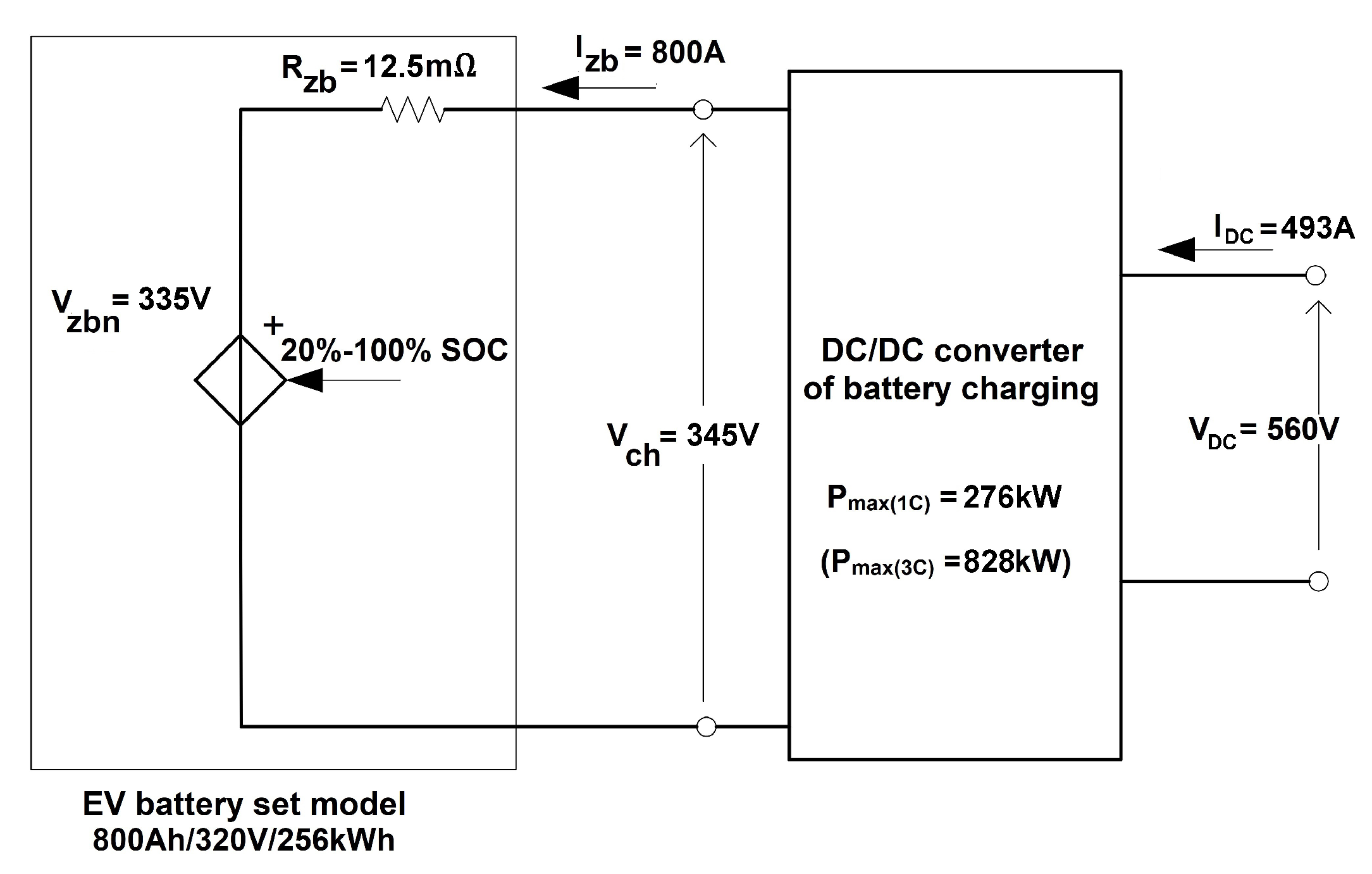
= 100 Ah. By connecting eight chains of 100 cells in parallel (100cx8ch), the final battery set 100cx8ch with the parameters 800 Ah/320 V is obtained, which corresponds to the capacity of 256 kWh. An equivalent diagram of an EV battery with a voltage DC/DC charging converter is shown in
Figure 1.
According to
Figure 1, it was assumed that a DC/DC converter with a minimum power of approx.
= 276 kW should be used to charge the battery set in 1 h with 1 C current or with a power of nearly 828 kW to charge the battery in about 20 min. with 3 C current. C rate is derived from Coulomb’s Law. The value of the charging current resulting from the battery capacity specified in Ah, e.g., 100 Ah means 1 C = 100 A. The possibility to charge an EV battery with 3 C current depends on its cooling capability, as the losses during charging increase three times compared to 1 C current. For 1 C current is
m
A
kW and for 3 C current is 3 × 8 kW = 24 kW. During continuous operation and while charging the battery, its temperature may not exceed
C [
22]. For customer is better, when the charging this battery current is 3 C (2400 A). The EV battery in this case will be charge in 20 min, but it is associated with a shorter battery life.
Different strategies are used to charge EV batteries, e.g., Constant Current (CC) 3 C (20–80% SOC) and Constant Voltage (CV) 80–100% SOC or charging with 10 C current pulse (20–80% SOC). A compromise should be found between charging time and battery temperature.
The equivalent internal resistance
of the battery pack intended to estimate charging power loses, can be determined based on the equivalent resistance of a single cell
. Several methods for determining
are known [
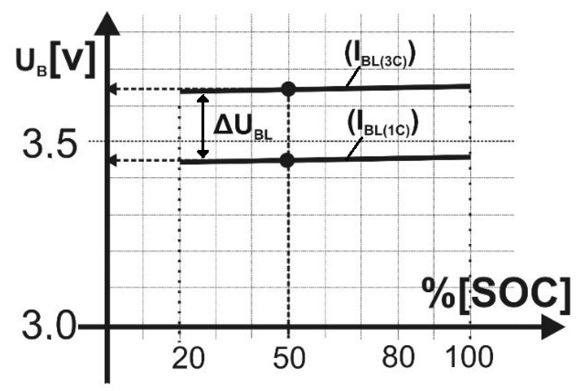
25]. The authors of this paper propose a method based on reading the cell charging voltage value at 1 C (
= 3.45 V) and 3C (
= 3.65 V) charging currents, which is given in the catalogue card [
26,
27]. Charging voltages for the Li-ion cells of the LFP100AHA type are linearly approximated and presented in
Figure 2. To the further simulation studies, an equivalent resistance was used, which reflects the power given to the battery by the converter.
Based on the reading of voltages for 50% SOC from
Figure 2, the equivalent internal resistance
of the single cell can be calculated (
1) as follows:
where:
—equivalent resistance of a single cell,
—difference of cell voltages for 3 C and 1 C charging currents,
—difference of cell charging currents 3 C (300 A) and 1C (100 A), respectively.
Then the equivalent resistance
of the 100c8ch battery set is equal to:
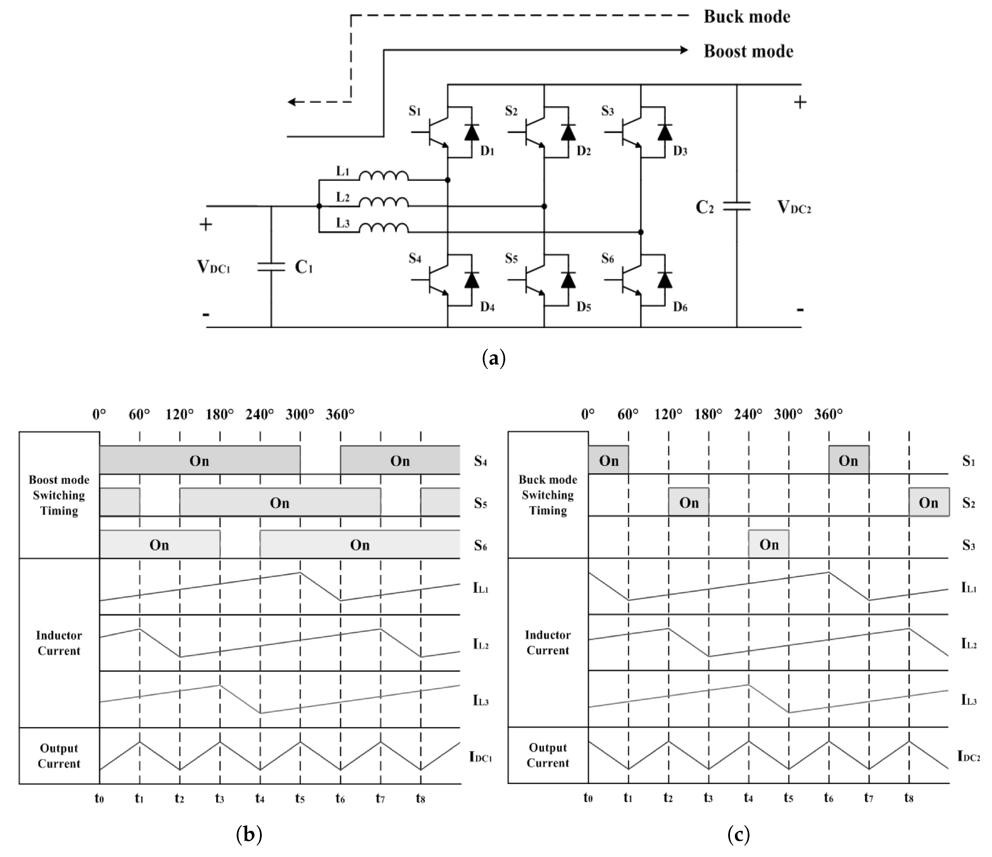
1.2. Bidirectional DC/DC Converter
DC output power supplies, such as energy storages, uses a bidirectional DC/DC converter for direct connection to DC microgrid. The type of DC/DC converter, shown in
Figure 3a, allows the converter current to be split into 3 branches, which are controlled with an
interleave method [
28].
Figure 3b,c show switching states and waveforms of currents in operating states of boost and buck mode, respectively.
Bidirectional DC/DC converters can be basically divided into isolated [
29,
30] and non-isolated types. In general, an insulated bidirectional DC/DC converter has the advantage of easily controlling voltage step-up and step-down through a transformer inside the converter, but the transformer used in the insulated type has a large volume. It has a disadvantage that the size and weight of the transformer are increasing with the power of the converter. On the other hand, the non-isolated bidirectional DC/DC converter has the advantage of being relatively simple in structure, has high efficiency, and reduced weight in comparison to the insulated type [
31]. In the non-isolated bidirectional DC/DC converter structure, various methods have been proposed to aim for higher efficiency, but among them, the interleaved method reduces the current stress of the power element because the magnitude of the load current (battery storage, DC microgrid) is divided into multiple phases. It has a feature of reducing the power device size and its current rating [
29,
32].
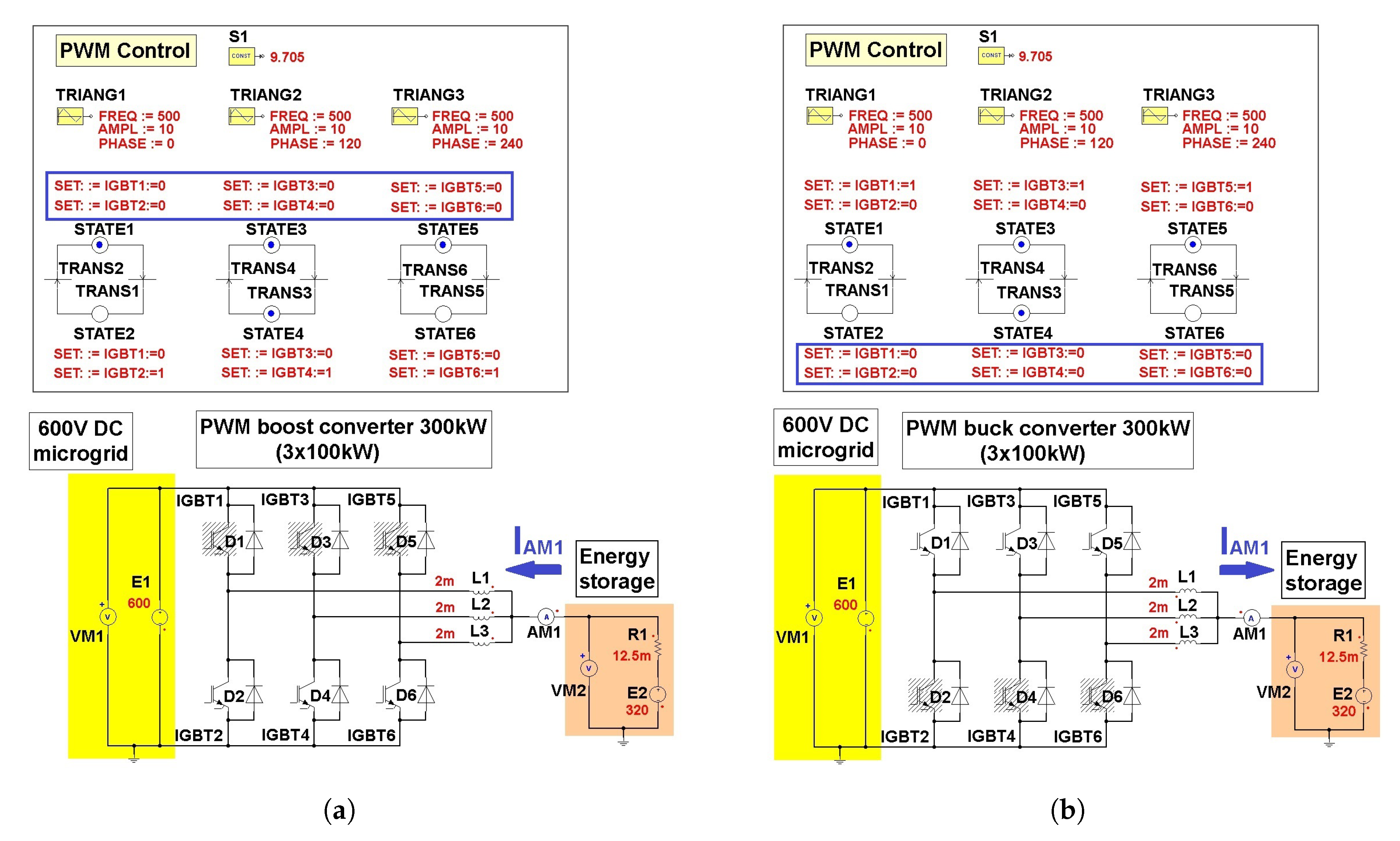
Tests of the battery (energy storage) charging current from the DC voltage line as a function of the converter control factor D (S1) are shown in
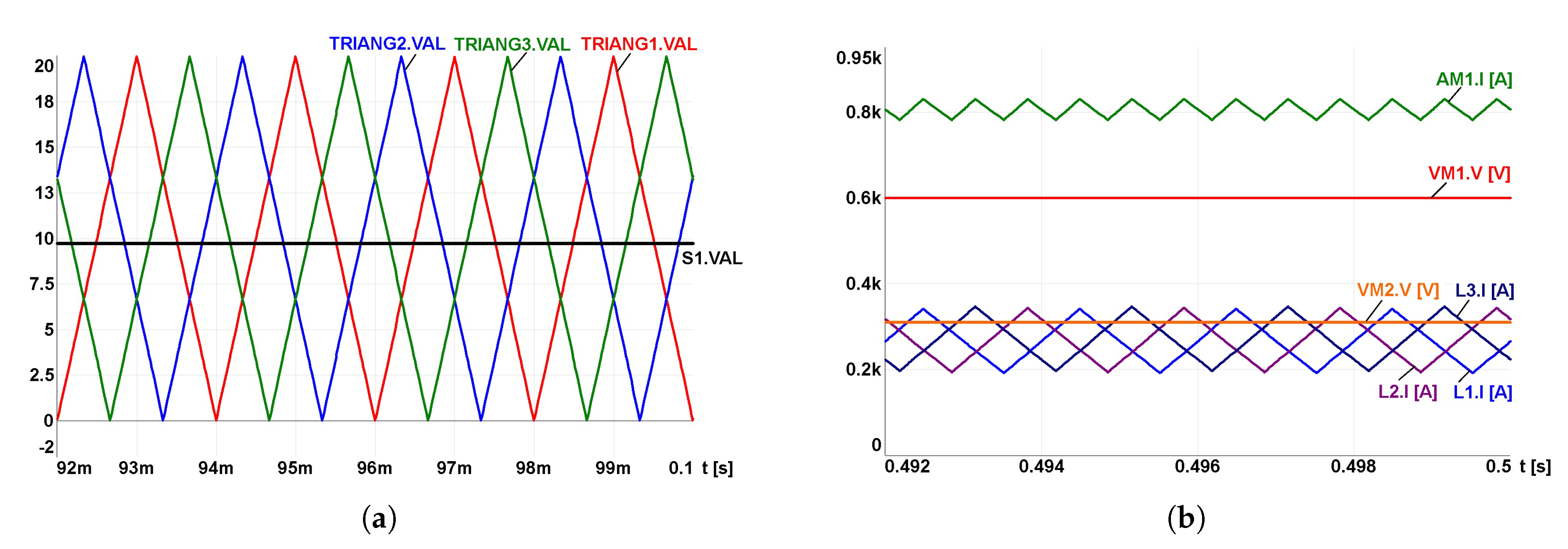
Figure 4a,b. They present the models of boost type and buck type of DC/DC converter respectively, which are simulated in ANSYS Simplorer. The inverter of each one is controlled by means of a state graph. Triangular modulation is based on the analysis of waveforms controlling IGBT power transistors and is implemented for each phase separately (TRIANG1 to TRIANG3). A constant value S1 representing the control factor D is given. It is presented on
Figure 5a.
Whereas,
Figure 5b presents phase currents L1, L2, L3 and voltage waveforms at selected points of the models from
Figure 4a. The DC/DC boost converter supplies energy to the 600 V DC voltage line (E1 source-VM1 voltmeter) from an energy storage with an initial voltage of 320 V (E2 source-VM2 voltmeter). To ensure constant charging current AM1 at different values of its voltage, the converter’s control factor D should be changed accordingly. The operation of a buck converter is analogous (model from
Figure 4b).
The authors proposed an alternative solution. In the same power electronic structure as the bidirectional DC/DC converter, it was produced AC voltage instead of DC voltage, because the different control of converter is used. The unidirectional converter used in regulated industrial drives to control the speed and torque of induction motors was investigated. The maximum voltage of the EV battery charging converter constructed in this way is determined by the value of the DC link voltage.
2. Drive Voltage Frequency Converters Used in the EV Charging Stations
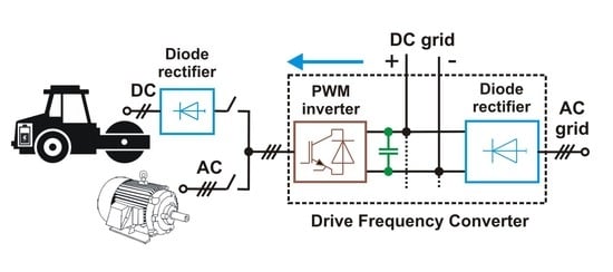
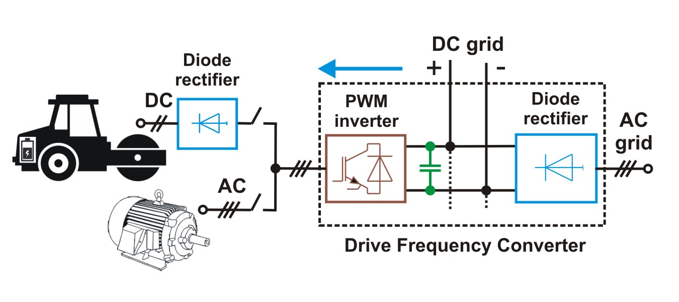
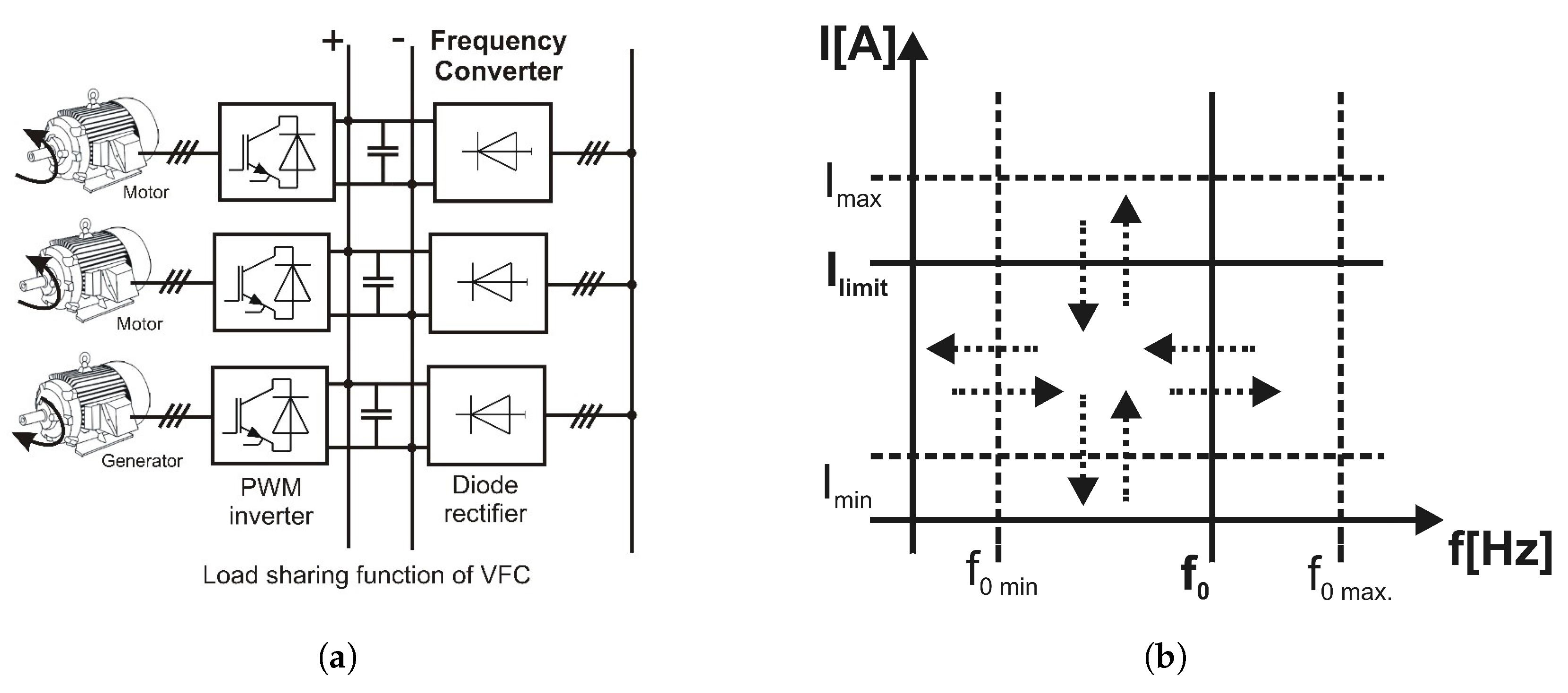
In a typical “load sharing” drive application, each VFC normally supplies power to a motor via the AC supply line. If one or more motors are driven in regenerative mode, they deliver power to the common DC bus. Then this power is used by other VFC and in this way the installation is more efficient, because in many situations the brake resistors can be omitted. In this situation the DC voltage (intermediate voltage) can be slightly different in each converter. This is due to minor differences in the rectifiers, different temperature, output power, etc. This small difference in DC voltage makes it necessary to use small line reactors in the AC main supply and fuses in the DC bus. The load sharing DC grid, which connect a few intermediate circuits of VFC, is presented in
Figure 6a [
33]. A large number of VFCs located in the various places of the local grid enables the location of EV battery charging points as close as possible to places of using the autonomous electric work machines and various types of EVs. Currently, all drives in which the engine speed is controlled, use indirect AC/DC/AC converters.
The
battery charging current can be set between the minimum current
and the maximum current
of the inverter,
Figure 6b. For the maximum frequency of sinusoidal voltage
, the condition is
= 10 [
21]. Increasing the frequency of the sinusoidal waveform
to a value above 50 Hz ensures a reduction of the alternating component in the rectified DC.
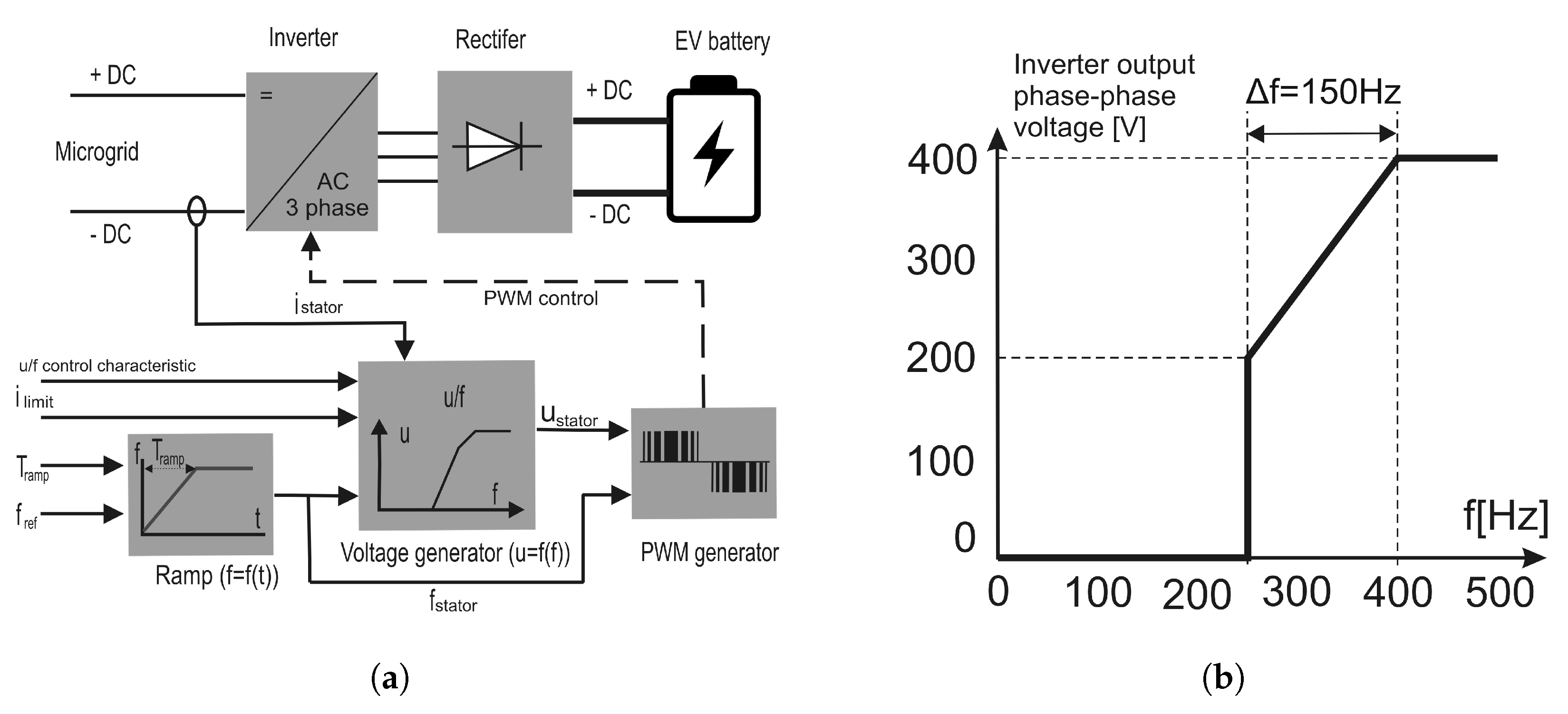
An example of basic drive VFC with scalar control, which is adapted to DC/DC converter, is shown in
Figure 7a. The CC battery charging strategy can use the inverter output current limitation function. The control systems of these converters can ensure any voltage characteristic as a function of frequency, typically
= const., or u/f = const. It enables to realise a special characteristic like the one shown in
Figure 7b, which is used for battery charging. This shape of u/f characteristic limits the frequency changing when the current limiter is active,
Figure 6b. The arrows indicate the possibility of setting any frequency and limit current values in the drive FC. When EV charger achieves the charging current
, it means that the battery is fully charged. The sinusoidal frequency of the inverter output voltage
is limited by the carrier frequency
of PWM. Frequency changes of 150 Hz causes the voltage to change between 250 V and 400 V. It is possible to choose a battery charging characteristic from four variable sets of VFC parameters,
Figure 7a [
21].
Frequently the control of a complex voltage vector in the drive VFC is used in the recuperative DC/AC converter that transfers energy from a DC microgrid to a three-phase AC grid. Drive VFC commonly uses the inverter current limiting function to protect motors against overload. This function can be used to set charging current of an EV battery.
3. DC Microgrid
By connecting all DC links of the sources and loads, a DC microgrid is formed,
Figure 8. The DC microgrid does not directly connect to the prevalent three-phase AC utility grid, like the AC microgrid, but via a bidirectional DC/AC converter for common integration. The use of this type of solution gives wide possibilities of cooperation of various generating units, such as RES. Functional microgrids focused on EV battery charging can become a basic element of charging infrastructure. The possibility of eliminating many stages of AC/DC and DC/AC conversion, could significantly reduce the cost of network components and power losses, and additionally increase the reliability of network systems. Moreover, the lack of reactive power, absence of harmonics and asymmetry of voltages and currents in the DC system, make the DC microgrid one of the key areas of application that contribute to significant benefits [
16,
17].
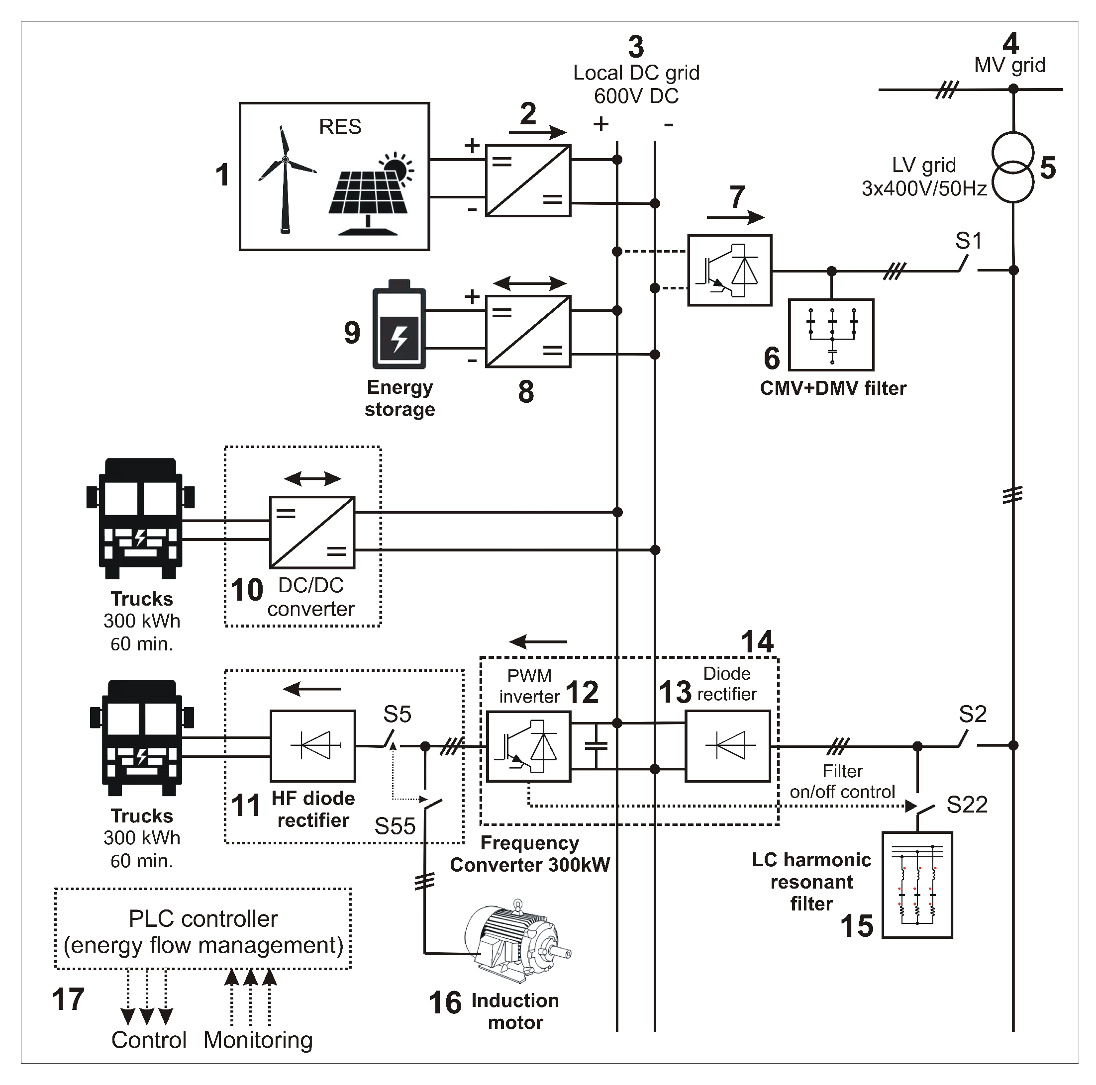
The own concept of hardware integration of the EV fast-charging station with the local LV DC microgrid (3) and the MV industrial power system (4) supplying the drive VFC (14) of the squirrel-cage induction motor (16) is presented in
Figure 8. The local DC microgrid is powered from three sources: renewable energy (solar or wind) (1), energy storage (e.g., Li-ion battery) (9) and MV power system (4) via LV grid (5). The hybrid DC power supply is optional, however, the extension of the power supply system with additional RES provides “clean energy” to the production process and relieves the power system. Reducing the so-called carbon footprint in products is now a mandatory requirement due to the increased effort to protect the environment. The EV battery is attached to the output rectifier (11). Implementation of the battery charging strategy, e.g., CC charging in the range of 20–80% SOC is controlled by a PLC controller (17), which for this purpose communicates with the inverter (12) of drive VFC (14).
A parallel resonant filter (15) is connected to the power supply of the drive VFC, which reduces the harmonic current of the input rectifier (13). To limit the effect of capacitive reactive power of the filter, it is switched on, if the VFC load exceeds the set value, e.g., when the drive VFC (14) load current exceeds 50% of the nominal current. The ES (9) accumulates excess energy generated by RES and maintains power supply for devices connected to the local DC microgrid during interruptions in the supply of energy from other sources. The ES is coupled to the DC microgrid via a bidirectional DC/DC converter (8). The task of this converter is to ensure charging of the ES according to the set strategy or supplying energy to the DC microgrid in accordance with the algorithm implemented in the PLC software (17).
The local RES power plant (1) supplies DC voltage to the microgrid (3) via a unidirectional DC/DC converter (2). The task of this converter is to supply renewable energy to the DC grid and minimize the energy consumed from the power system (4). During a significant deterioration of power quality indicators in the power system or the occurrence of surplus renewable energy, it can be sent to the system via a DC/AC inverter (7), which cooperates with the LCL filter group (6) to limit the content of high-frequency differential-mode (DM) and common-mode (CM) voltage produced by the PWM Active Front End (AFE) recuperative inverter (7) [
34,
35].
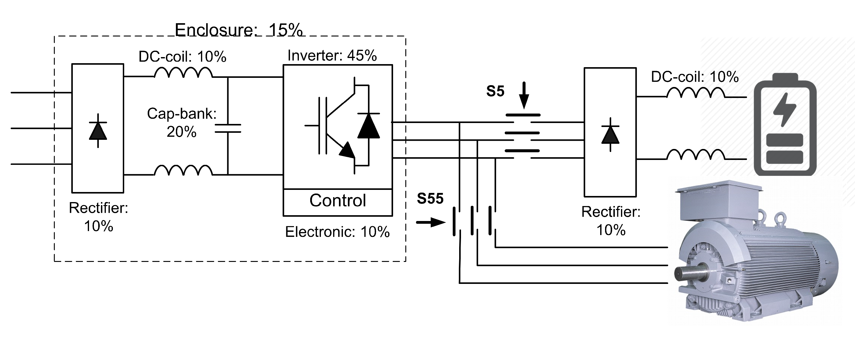
The authors carried out research showing the possibility of using drive VFC as inverter components for fast charging of EV batteries, which is depicted in
Figure 9.
The mathematical model of the bipolar PWM inverter of the drive VFC connected with a six-pulse diode rectifier is presented in
Figure 10. The model is written with electric symbols representing ideal energy sources, ideal passive elements and linearized models of controlled and non-controlled power electronics. The electrical differential equations of the DC/AC/DC converter are solved using an ANSYS Simplorer. The obtained results of simulation tests of the presented model confirm the possibility of controlling the direct voltage value of the diode rectifier charging the EV battery. Experimental tests carried out on the laboratory stand confirmed the results of simulation tests. The battery constant voltage obtained here is characterized by stability and negligible ripple. A detailed description of the operation of the EV battery charging rectifier and the PWM inverter is not the subject of this study.
Drive VFCs with two-level voltage inverters are usually available with a six-pulse diode rectifier or less often with an AFE rectifier [
21]. The basic types of drive converters used in LV grid are shown in
Figure 9. The digital designations of the VFC components in
Figure 9 refer to the hardware configuration of the hybrid EV fast-charging station shown in
Figure 8. Proposed hardware combination of a hybrid EV charging station power supply system contains a significant part of the components used in industrial drive systems.
4. Simulation and Experimental Tests of Novel EV Charger
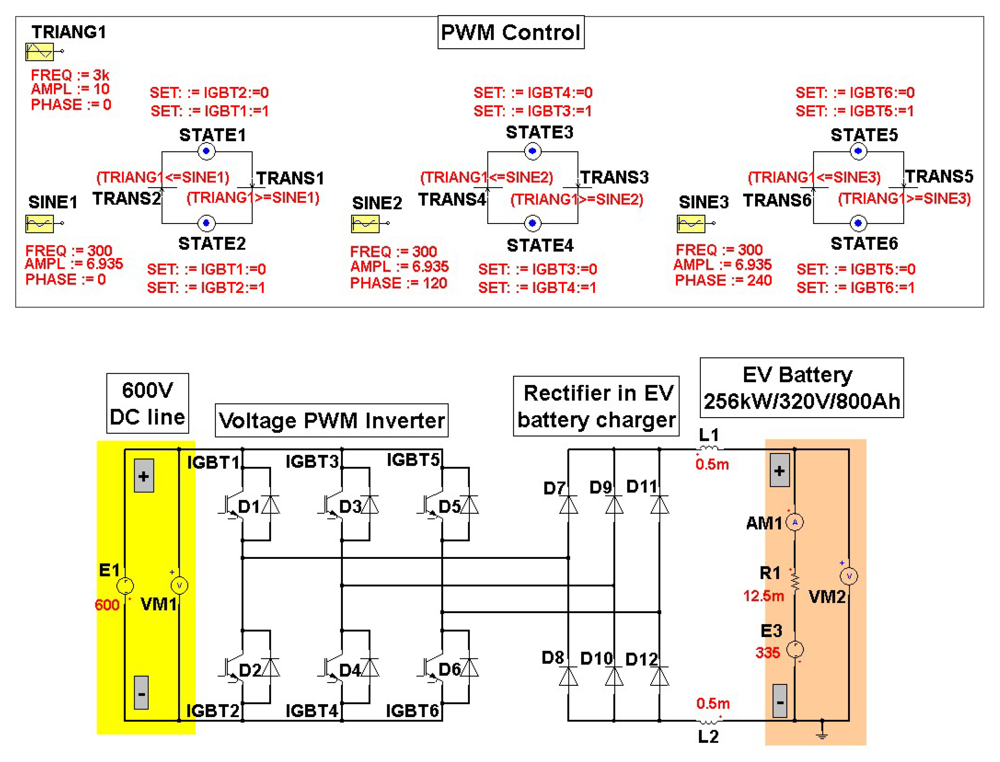
The electrical diagram of the simulation linear circuit model of a three-phase EV charger is depicted in the
Figure 10. The EV battery is represented with a resistor R1 and voltage source E3. Using different values of sinusoids frequency and its amplitude in the inverter PWM control (SINE1, SINE2 and SINE3 PWM control-
Figure 10), it was possible to test the EV charger properties for different values of the modulation factor M and the frequency of modulating voltages. The frequency of the triangular carrier waveform of PWM modulation was set in the TRIANG1 module and
= 3 kHz was used. It is a typical carrier frequency for inverters in the industrial high power drives. The frequency of SINE modules is 300 Hz, and it was the maximum output sinusoidal frequency of industry drive FC used in the laboratory stand. The modulation factor M can be changed between 0 and 1.25 to control output inverter voltage.
The use of the PWM modulator model described by the state graph made it easy to control the inverter IGBT transistors in relation to the sinusoidal PWM pattern. It was assumed that all model elements used in electrical circuits had linearized parameters.
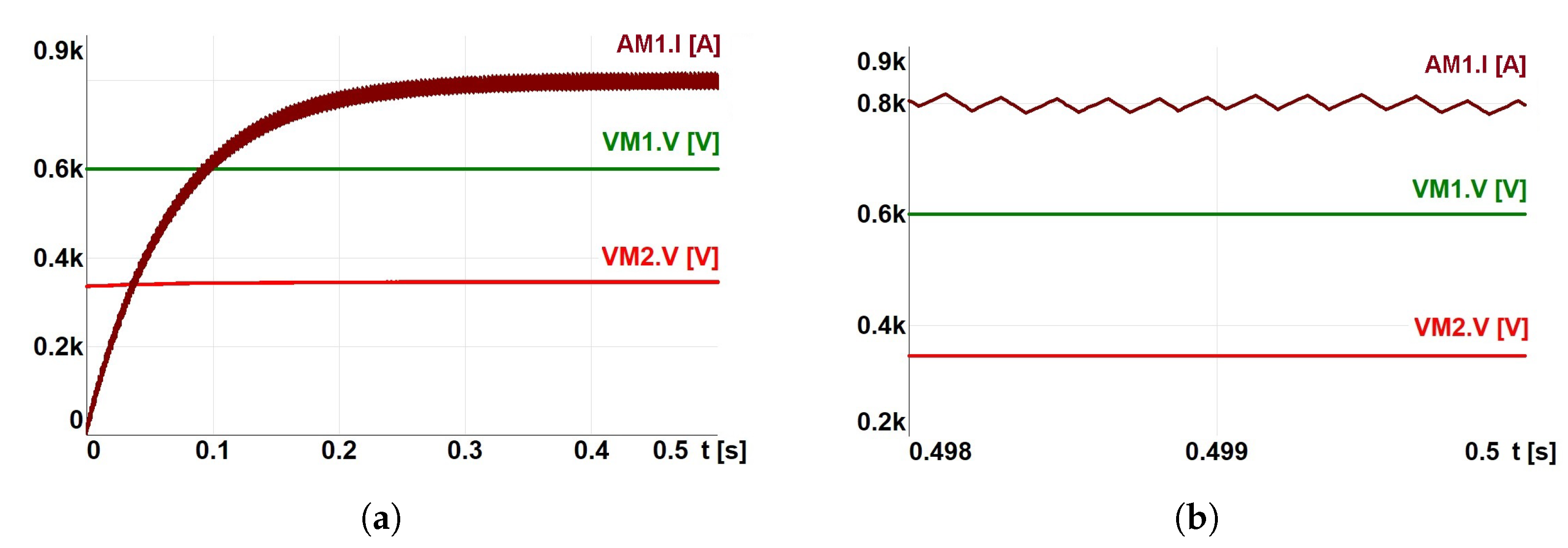
To receive the constant charging current 800 A, the control of the modulation factor value M was used.
Figure 11a,b show the obtained results of current and voltage waveforms, which are depended on the modulation factor’s value (according to the model from
Figure 10, M = 0.6935). The EV battery charging current 1 C was used in the test. The value of the charging current results from the technical specification of tested the Li-ion battery [
22]. In the case of continuous modulation (the maximum value of modulation factor is M = 1), the EV battery voltage increased and the current exceeded the permissible charging value, which could destroy the EV battery. Therefore, it is important to choose the appropriate value of the modulation factor M, which allows battery charging with constant current for nominal pack voltages at the level to about 500 V [
36].
The tests of a diode rectifier powered by an inverter were performed under the following conditions:
without chokes of LC filters (3, 4) downstream of the inverter and in the rectifier,
with two types of LC filters of inverter DM voltage (3, 4),
without DM filter, but with DC chocks in the rectifier.
In case 1, it was not possible to adjust the value of the rectified voltage. In case 2, the impedance of the LC filter chokes caused an unfavourable significant drop in the rectifier supply voltage. Case 3 made it possible to control the rectified voltage in a wide range. Moreover, the elimination of the capacitors on the DC side of the rectifier did not significantly increase the AC component in the rectified voltage.
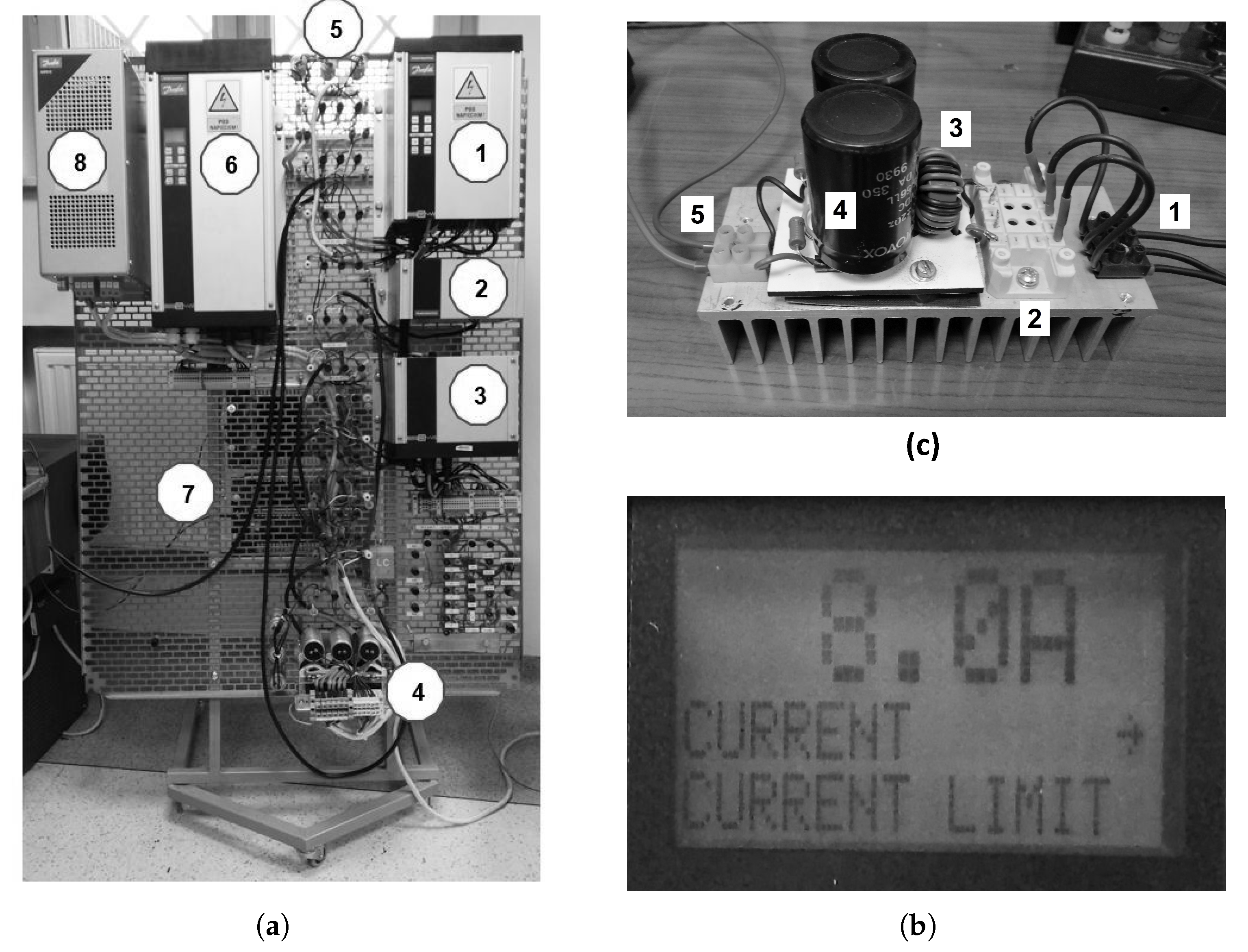
The specification of laboratory stand depicted in
Figure 12a is presented in
Table 1.
When the negative pole of the load (EV battery) is grounded, the CM voltage is absent in the rectified voltage. Therefore, there is no need to filter the inverter CM voltage by using the capacitors (No. 5,
Table 1) attached to the DM filter from one side and AC phase voltages from the second side.
Given by the VFC drive current limitation, the rectifier load current maintained a constant value thanks to automatically lowering the rectifier supply voltage by the inverter control system.
Figure 12b shows the programmed value of the maximum output current 8 A of low voltage (3 × 400 V/50 Hz) and small power (5.5 kW) industrial VFC drive (No. 6,
Table 1). The maximum value of the rectified current did not exceed 10 A, which resulted from the power balance (
).
Figure 12c shows the six-pulse diode rectifier built for drive VFCs of the laboratory stand. Drive VFC outputs (1) were connected to a fast six-diode rectifier (2) with ferrite anti-distortion filter (3) and capacitor bank on the constant voltage side (4) of the rectifier, thus it was possible to charge EV batteries with DC current (5). The DC voltage fluctuations did not depend substantially from the value of the capacitor bank, because the inverter frequency of fundamental voltage harmonic was set to 300 Hz.
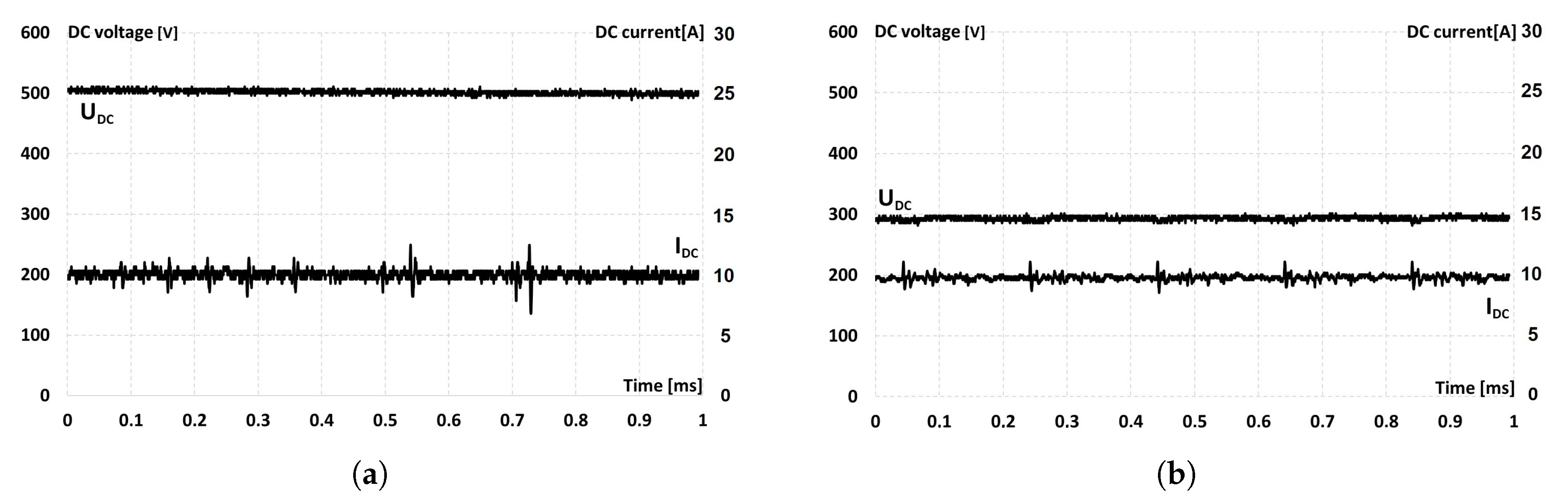
The received output DC voltages and DC currents are presented in
Figure 13, for the capacitor bank equal to C = 16
F. By comparing
Figure 13a,b, the effective operation of the EV battery charging current stabilizer was visible. The rectifier voltage depends on the value of load resistance. A two-times decrease of the resistance resulted in a decrease of the charging voltage from 500 V to 300 V. In
Figure 13a the DC voltage and charging current had a constant value and the output power was about 1 kW. When the rectifier was loaded with the resistance of 30
(
Figure 13b), the voltage supplying of the six-pulse diode rectifier automatically decreased. The load current was at the same value of 10 A in accordance with the set point of current limiter in the drive VFC.
The operation of the drive VFC could be programmed to perform expected functions of an EV battery charger. The experimental tests done for low power setup confirmed the correctness of performed simulation tests and the possibility of using the drive VFC as the basic DC/DC converter component of EV fast chargers.
5. Discussion
When charging the EV battery, the voltage inverter does not use freewheeling diodes (they are inactive), because there is a unidirectional energy flow from the DC microgrid to the diode rectifier. Therefore, it should be assumed that the efficiency of charging system will be similar to the efficiency of a drive VFC. The rectifier diodes cause losses similar to those in the inverter freewheeling diodes when supplying an induction motor.
If the drive converter is powered only from the DC microgrid, then it is possible to use one integrated circuit with an inverter and a rectifier to build a DC/DC converter for charging EV batteries.
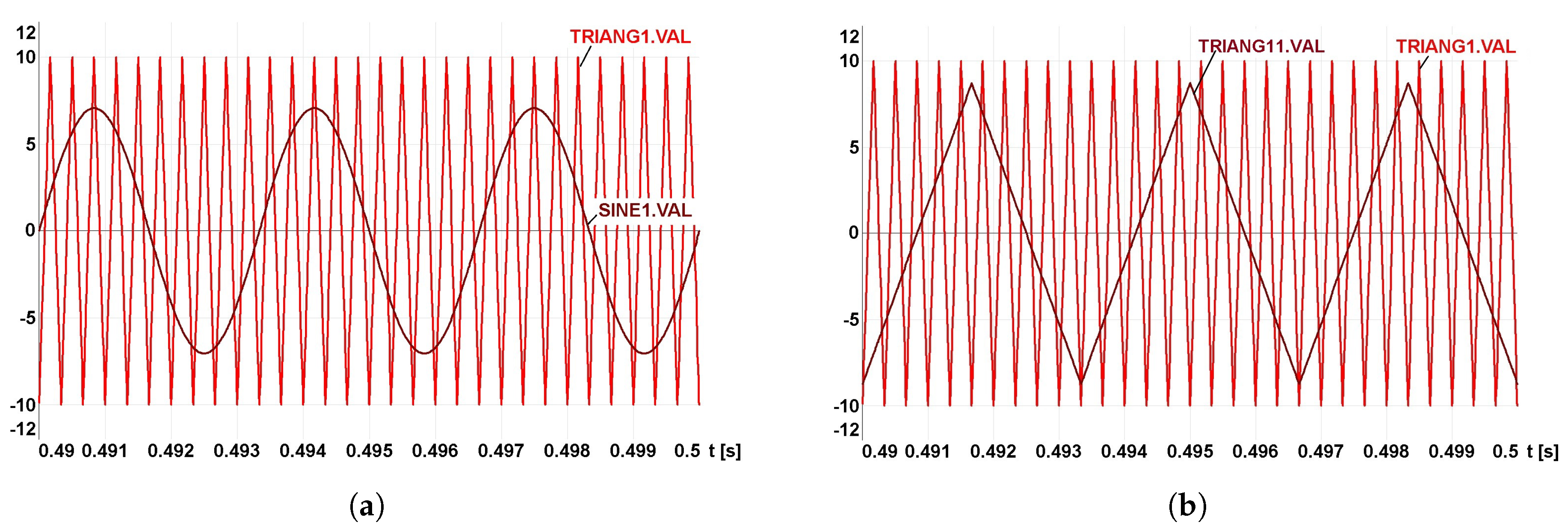
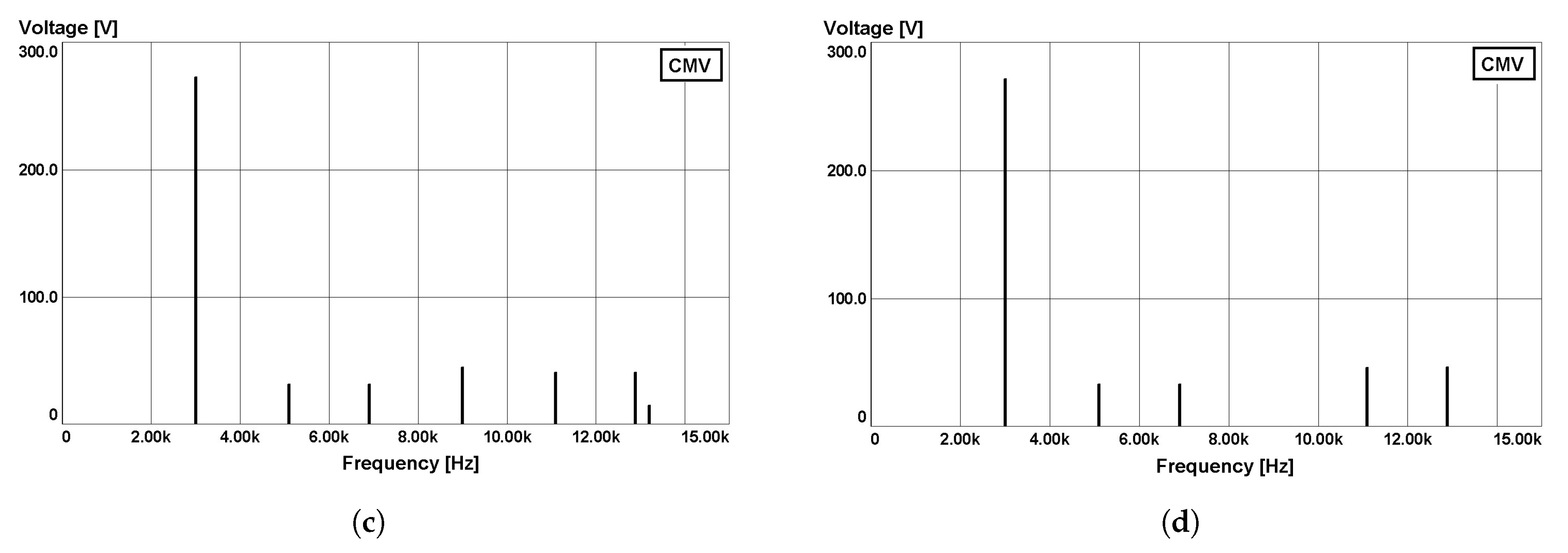
When building a new converter for battery charging purposes, it is possible to replace sinusoidal modulation, e.g., with triangular modulation. The advantage of using the triangular PWM
Figure 14b instead of the sinusoidal PWM (
Figure 14a) is the proportional dependence of the value of rectified voltage and modulation factor M. As the amplitude of the triangular of the modulating wave increases linearly (TRIANG11-
Figure 14b), there is a directly proportional increase of width modulated pulse. Such proportionality does not occur if the modulating waveform is a sine wave and the modulated waveform is a triangular wave [
34]. The spectral analysis of the inverter CM voltage for sinusoidal and triangular modulation shows that there are no significant differences in the CM voltages, in these both kind of PWM modulations as shown in the
Figure 14c,d respectively.
6. Conclusions
The authors proposed a DC 600 V microgrid, which is connected to the intermediate circuits of drive VFC used in the induction motor drives. Thanks to this solution, the efficiency of electric drives has increased, as energy losses on brake resistors for drive converters have been eliminated. The actual efficiency of the converter has not been experimentally tested. The efficiency can be estimated on the basis of the efficiency of the driving frequency converters (VFCs), which reaches values of 98% [
21].
In the proposed solution, there are also losses in the rectifier, but the reactive component of the current does not flow via the freewheeling diodes of the inverter while charging the EV battery. The reactive component of the current flows via the freewheeling diodes of the inverter while supplying induction motors. Therefore, the authors conclude that the efficiency of the proposed converter for charging EV batteries will be similar to the efficiency of the drive converter.
The bidirectional converter is an adjustable current source for battery and it was used as an example of fast charging battery converter in this paper. The authors’ solution is a converter with adjustable EV battery voltage source. Using of the drive frequency converter as an EV battery charging converter is a novel solution where EV battery is charged via a constant voltage source with regulated value.
The energy supplied by the generator is transferred to the energy storage or other converters connected to the microgrid (load sharing). RES and ES cooperate with the microgrid, which has a hybrid DC converter power supply system for fast charging of EV batteries. Scheduled EV battery charging was used, which is carried out in such a way that when the motor is powered by a frequency converter, it is used to charge an EV battery or a mobile electric work machine. The battery charging converter has been developed through the adaptation of drive VFC, consisting of the attachment of a diode rectifier. The VFC drive is used to set the rectifier DC voltage value. The phase voltage value and frequency are controlled by the PWM drive parameters of the drive VFC inverter.
The use of a microgrid provides the opportunity to integrate a hybrid power supply system for fast EV charging stations in such a way that the battery charging energy does not increase the load of the power system and in addition has an impact on worsening the power quality indicators in the power system.


