Article

Study on the Coupling Effect of a Solar-Coal Unit Thermodynamic System with Carbon Capture

1
School of Water Conservancy and Electric Power, Hebei University of Engineering, Handan 056000, China
2
Electronic and Information Engineering, Handan Polytechnic College, Handan 056000, China
3
Key Laboratory of Solar Thermal Energy and Photvoltaic System of Chinese Academy of Science, Institute of Electrical Engineering, No. 6 Beiertiao, Zhongguancun, Beijing 100190, China
*
Author to whom correspondence should be addressed.
Energies 2020, 13(18), 4779; https://doi.org/10.3390/en13184779
Submission received: 12 July 2020 / Revised: 25 August 2020 / Accepted: 8 September 2020 / Published: 14 September 2020
(This article belongs to the Section F: Electrical Engineering)

Abstract

:
Based on the structural theory of thermo-economics, a 600 MW unit was taken as an example. An integration system which uses fuel gas heat and solar energy as a heat source for post-combustion carbon capture was proposed. The physical structure sketch and productive structure sketch were drawn and a thermo-economics model and cost model based on the definition of fuel-product were established. The production relation between units was analyzed, and the composition and distribution of the exergy cost and thermo-economic cost of each unit were studied. Additionally, the influence of the fuel price and equipment investment cost of the thermo-economic cost for each product was studied. The results showed that the main factors affecting the unit cost are the fuel exergy cost, component exergy efficiency, and irreversible exergy cost of each unit, and the main factors affecting the thermo-economics cost are the specific irreversible exergy cost and investment exergy cost. The main factors affecting the thermal economics of solar energy collectors and low-pressure economizers are the invested exergy cost, negentropy exergy cost, and irreversible exergy cost of each unit.

Graphical Abstract

1. Introduction

Climatic change resulting from greenhouse gases has become the most serious air pollution problem facing humanity at present [1]. The flue gas emissions from coal-fired power plants represent the largest CO2 emission contributor, and the trend will continue in the foreseeable future [2]. Considering this, CO2 capture and storage (CCS), resource utilization of CO2, and renewable energy, as three measures that appeared successively, remain the Gordian techniques for rapidly and effectively reducing CO2 emissions. According to the prediction of the Global CCS Institute in 2018 [3], a 14% cumulative CO2 emissions reduction must be achieved in order to reach the Paris target by 2060 [4].
The widespread use of renewable energy is deemed an effective way of reducing CO2 emissions. As renewable energy, solar energy has a wide range of applications at home and abroad in many fields [5]. However, carbon capture is deemed the most immediate way of decreasing CO2 emissions. Post-combustion CO2 capture (PCC), oxygen-enriched combustion, and chemical looping combustion are prospective technologies which can be applied to active coal-fired power plants [6]. However, the high energy consumption of carbon capture desorption impedes the development of post-combustion CO2 capture. In the case of solvent absorption, thermal energy consumption (3.11–4.0 MJ/kgCO2) is required for reboiler heat duty [7]. To this end, it is very important to explore a low-carbon economy-energy-saving emission reduction road. Controlling the emissions of carbon dioxide and nitrogen oxides from fossil fuel power plants is an important way of reducing greenhouse gas emissions in the environment. On the basis of coal-fired units, the rational integration of solar thermal utilization systems to form an integrated system of pollutant emission reduction for solar-assisted coal-fired units is an effective way of achieving energy conservation and emission reduction.
In recent years, many scholars have conducted research on the hybrid power generation technology of the solar generation system, CO2 capture, and fossil fuel units [8]. To make post-combustion CO2 capture (PCC) more suitable for coal-fired power plants, growing interest has been directed to the flexible operation of PCC [9]. The resource utilization of captured CO2 as a carbon source for the production of energy storage media offers a technological solution for overcoming CO2 emissions [10]. Beatrice Castellani [11] aimed to assess the carbon and energy footprint of an innovative process for carbon dioxide recycling. A techno-economic study of the proposed system, which integrated solar energy into an 800 MW coal-fired power plant, was conducted [12]. A novel solar tower-aided coal-fired power plant has also been proposed, in which solar energy is used to reheat exhaust steam from an immediate turbine to improve the operating parameter of the regenerative cycle [13].
Research on synthetic oil heated by solar energy, steam extraction, gas turbines, and so on, as the heat source of the carbon dioxide capture system, has been conducted [14,15]. Most of these studies have focused on case analysis, conventional economic evaluation, and feasibility analysis. Additionally, several solutions have been studied in an attempt to decrease the energy penalty of solar-aided CO2 desorption capture from coal-fired power plants. The idea of solar-aided desorption for carbon capture first appeared in Australia [16]. The systemic structure, feature, and energy-efficiency performance for the integrated system of solar-aided power plants have been proposed, and life cycle theory has been used to analyze solar-aided power plants for carbon desorption processes, including life cycle assessment and cost analysis [5].
However, the study of integrated systems lacks theoretical research at the system level. To this end, according to the energy consumption characteristics of carbon capture and the energy consumption of the liquid ammonia evaporator in the denitrification system, this study proposes integrating the flue gas waste heat and solar heat into the thermal system of the coal-fired unit, with the aim of comprehensively seeking the feasibility of integrating the solar-aided CO2 desorption with the coupling system regarding the thermo-economic cost performances of the presented system. Firstly, a process description of the proposed system is presented from a thermo-economic perspective. Specifically, in order to analyze the system performance more clearly, the physical structure and productive structure of the solar-aided coal-fired power plant are presented. We provide a new method for calculating the performance of the main equipment based on structural theory. We also use the exergy cost to evaluate the production performance of the entire system and main equipment, and quantitatively study and analyze the main reasons leading to the increase in the production cost of the coupling system. In addition, based on the thermo-economic model, the change law of the unit thermo-economic cost of the product is analyzed.

2. Methods and Models

2.1. Pollutant Emission Reduction Method of a Solar Auxiliary Coal-Fired Unit

The parabolic trough solar collector is one of the solar collectors with a medium temperature. All of the solar thermal generation systems operated commercially in America and Europe apply this technology. Currently, many research institutes are trying to find a way to combine this technology with fossil fuel power plants. When water is used as a medium which is heated by the direct steam generation (DSG) solar trough collector integrated with the coal-fired unit, there is not only energy transfer, but also the exchange of substances between the two systems. When the flue gas waste heat and the DSG solar collector provide the heat source for the post-combustion carbon capture system, and the unit steam extraction provides the heat source for the liquid ammonia evaporator in the denitration system, the matching of the material flow and energy flow needs to be considered; that is, a certain amount of water is drawn from a certain part of the thermal system to be heated by the flue gas waste heat system and the solar heat collection system, which provides a heat source for the carbon capture system.
In this paper, the N600-24.2/566/566-type generator set is taken as the research object, according to the calculated acid dew point temperature, the low-pressure economizer is used to heat the No. 3 low-pressure heater (3DJ) to draw the working fluid [17,18,19], and the solar heat is then collected by the DSG parabolic trough collector [20]. Furthermore, condensed water is heated to the conditions required for regeneration of the amine-based catalyst and then introduced into the reboiler as a heat source for regeneration of the desorbent solution in the carbon dioxide capture system, using its latent heat of vaporization to provide the reboiler solvent regeneration requirements. At the same time, steam extraction of the unit is used to provide a heat source for the liquid ammonia evaporator in the denitration system. In view of the unbalanced solar radiation, in order to ensure that the solar-assisted coal-fired system can produce a balanced amount of heat required for desorbent regeneration, heat storage needs to be installed in the system. Considering the parameter matching, the water returned after heating the reboiler is introduced into the inlet of the No. 5 heater. The integration scheme is shown in Figure 1.

2.2. The Model of Structural Theory for the Integration System

In general, the “fuel-product” is used to define the input and output of components in thermo-economics. The input and output of the integration system are analyzed according to the physical structure, including the physical structure and production structure. Among them, the physical structure reflects the physical association between equipment components, and the production structure reflects the production relationship of the system. In order to clarify the input and output of each component, it is necessary to divide the physical structure of the thermal system and determine the “fuel” and “product” of each component [19,20].

2.2.1. Physical Structure

According to the function of each device, the integrated system is divided into the physical structure shown in Figure 2. According to the arrangement of the steam extraction ports, the steam turbines are divided as follows: The regulating stage serves as a component, and the remaining steam extraction ports and steam extraction ports form a component. The steam leakage and shaft seal systems are grouped into the corresponding steam turbine stage group; each device of the regenerative system is used as a component; the shaft seal heater and the adjacent low-pressure heater are combined into a component; the boiler is divided into a superheater component (13) and a reheater component (17); and the steam turbine (25), condensate pump (28), solar collector field (5), carbon dioxide capture system (6), denitration system (26), and low-pressure economizer system (4) are considered to be components, respectively.

2.2.2. Production Structure

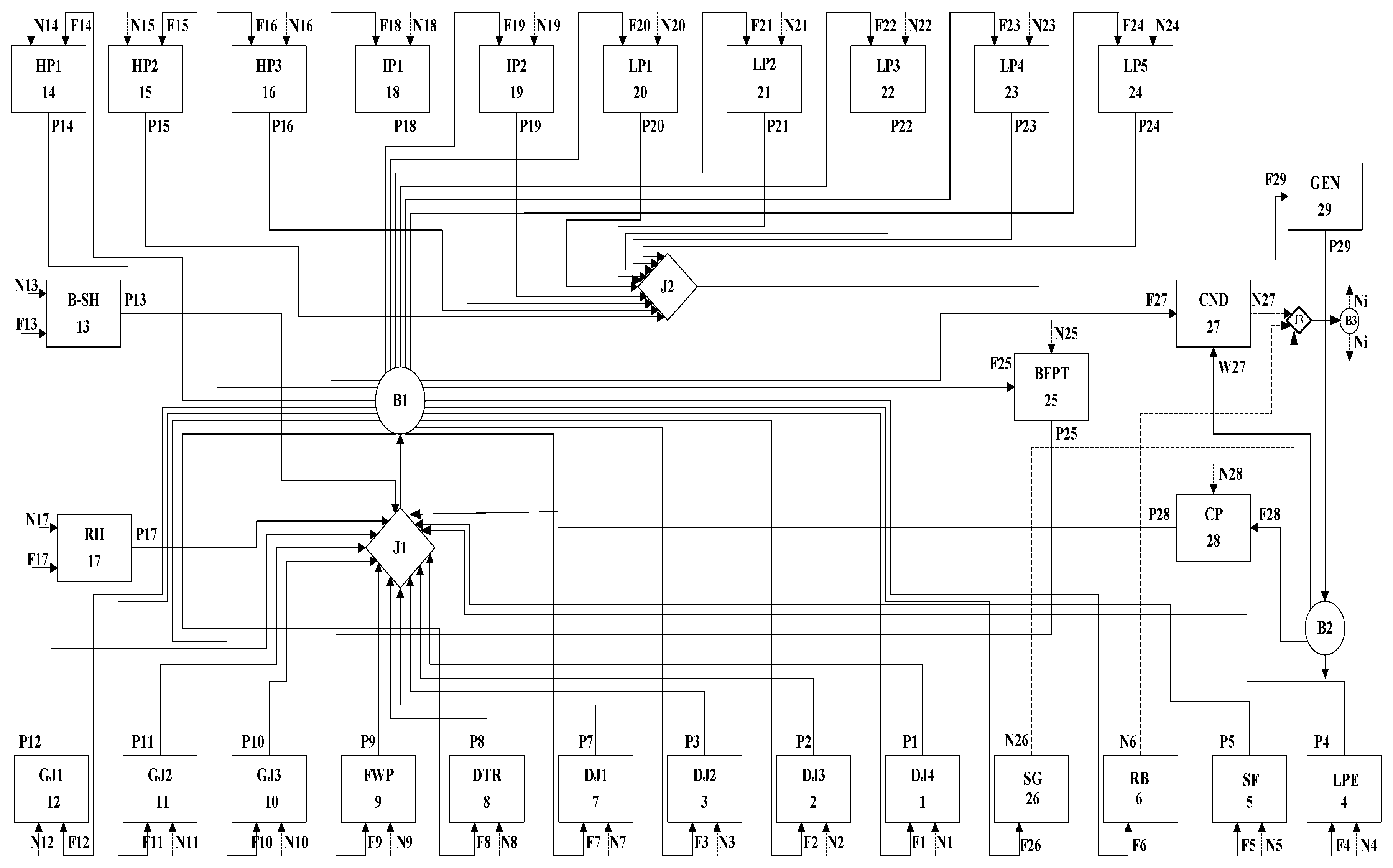
In this study, the “fuel-product” is used to define the production purpose of each piece of equipment. The product (P) is the purpose of the component which is quantified by exergy and the fuel (FB) is the exergy consumption. According to the function of the production equipment in the overall situation, the actual flow of the input and output of each piece of equipment is decomposed or combined to obtain multiple fuel flows and product flows. In this way, the physical structure diagram of the actual system can be converted into a production structure diagram represented by the “fuel-product”, as shown in Figure 3. In Figure 3, rectangles represent physical components, diamonds represent influx components, and circles represent branch components. The arrows F, P, and N of every physical component represent the fuel consumption, the product, and the negentropy consumption, respectively. In the influx or branch components, the inlet and outlet of the exergy or negentropy remain balanced.
The production structure diagram is a graphical representation of the production relationship of the integrated system, which intuitively reflects the production relationship in the power plant. The product P of each component is collected by the influx component J, and then redistributed to other components through the branch component B. When the investment cost of equipment (external resources) is taken into account, it can be directly input into the corresponding component, and the mathematical Equation (1) of the thermo-economics model can be obtained according to the production structure diagram.
B i = g i ( B j , x l )                                       i = 1 , , m
where Bi is the inlet flow of each component, xi is the internal parameter set of the component, Bj is the output stream of the component, m is the number of components in the production structure, and Gi () is the function between Bi and Bj and xi of the i component. Every input and output flow in the production system is always represented by exergy, negentropy, cash, enthalpy, or entropy. The internal parameter set xl is usually represented by pressure, temperature, efficiency, and so on.
Setting up a model based on thermo-economics usually requires the thermo-economics model to be defined with a linear equation. When the characteristic equation is a homogeneous first-order equation on subset Bj, according to Euler theorem, Equation (1) can be represented as
B i = j = 1 n ( g i B j × B j ) = j = 1 n k i j B j
where n is the number of input flows and kij is the technical product coefficient, which represents the proportion of product consumed from component i when the unit product is produced by component j. The n × n dimensional matrix <KP> composed of kij is the unit exergy consumption matrix, which reflects the distribution of the fuel and product in the structure.

2.2.3. Characteristic Equation

Generally, three types of characteristic models are included in the thermo-economics model: Characteristic equations for production and dissipation components, structural equations for aggregate and branch components, and cost calculation equations. The sum of kij, which is the technical production coefficient of a component, is the unit exergy consumption of this component, and can be calculated by Equation (3).
k j = i = 0 n k i j = i = 0 n F i / P j = F j / P j
where P is the product, kw; F is the fuel, kw; and i and j represent the i-th component and the j-th component, respectively.
The characteristic equation of the production and dissipative component is calculated by Equation (4), which reflects the relationship between production functions Pi and the fuel Fi of the i-th component with unit exergy efficiency (ki).
F i = k i P i
The structural equation is composed of the aggregate component Equation (5) and the branch component Equation (6).
F i = r i j P j
where rij represents the efficiency and pj is the product of the j-th aggregated component.
F j = i = 0 m P i
where Fj represents the fuel of the j-th branch assembly.

2.2.4. Exergy Cost Equation

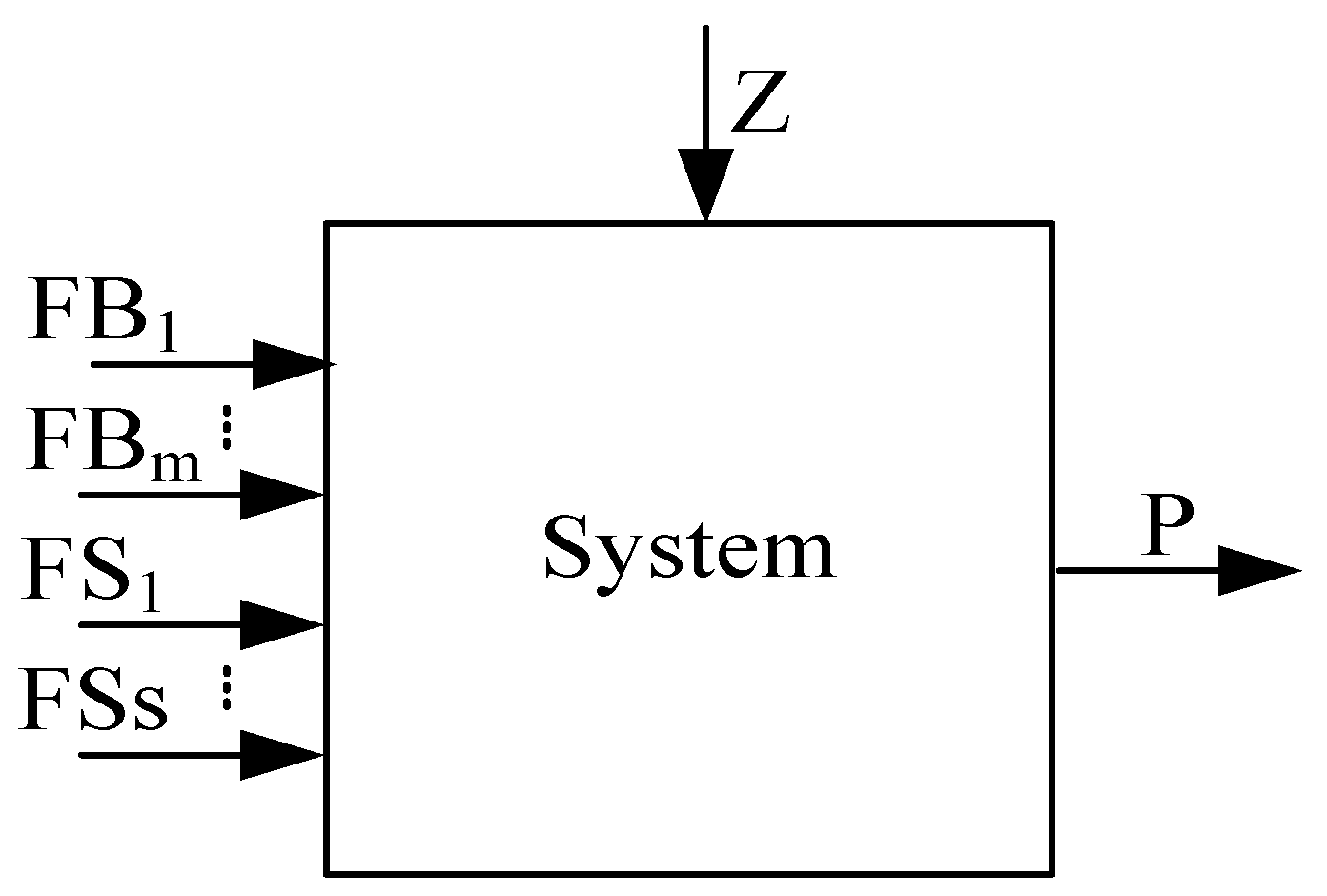
The exergy cost is defined as the amount of exergy required to generate exergy flow in the system. The unit cost refers to the amount of energy consumed per unit of stream produced, and its dimension is the ratio of exergy to exergy, which is denoted as k*. The unit exergy cost includes the exergy cost of unit product k p * , exergy cost of unit fuel k F B * , and unit negentropy exergy cost k F S * . Figure 4 shows the structural diagram of an energy system.
In Figure 4, FBm is the fuel input of a system, kW; FSs is the negentropy input of a system, kW; Z is the non-energy cost input of a system; and FBm, FSs, Z, and P represent the fuel input of the system, the negentropy, the non-energy input, and the product, respectively. The exergy cost equation of the above system is calculated by Equation (7), and the unit exergy cost equation is calculated by Equation (8).
k P * P = i = 1 m k F B , i * F B i + i = 1 s k F S , i * F S i
k P , i * = i = 1 m k F B , i * F B i P + i = 1 s k F S , i * F S i P   = i = 1 m k F B , i * k B i + i = 1 s k F S , i * k S i               = ( 1 + k I i ) k F B , i * + k S i k F S , i * = k F B , i * + k I i k F B , i * + k S i k F S , i *
There are multiple exergy flows transferring between systems or components. Therefore, the calculation equation of the unit product exergy cost is
k P , i * = k 0 , i + j = 1 n k j i k P , j * i = 1 , 2 , , n .
The cost equation expresses the investment cost of the system as a thermodynamic variable and a functional form of the component product. The unit thermo-economics cost cp of the product belongs to the economic dimension, and its calculation method is Equation (10).
( U - K P t ) c P = ( c e + k Z )
In Equation (10), U is a 29 × 29-dimension unit diagonal matrix, <KP>t is the 29 × 29 dimension transpose matrix of the unit exergy cost, ce is the product vector (10−6 ¥/kJ) of the unit price cFuel and k0.i, cFuel is equal to the ratio of the coal-fired price to coal-fired calorific value, and k0.i represents the unit exergy cost of the components by directly obtaining fuel from the environment. kZ is the vector of cost capital (¥/kJ), which reflects the external investment and other costs needed by the components. Therefore, Equation (10) can be further divided as follows:
c p i = k B i c F B , i + k S i c F S , i + k Z i = c F B , i + k I i c F B , i + k S i c F S , i + k Z i .

3. The Results and Discussion

By applying the structural theory of thermo-economics in the integration system, the formation and distribution of the generation cost can be analyzed in the carbon capture system of a power plant, and the internal reasons of the generation cost increase can be revealed. Table 1 shows the unit cost of each component (product cost, negative entropy cost, fuel cost, etc.) of the solar-assisted coal-fired unit pollutant emission reduction thermal system under turbine heat acceptance (THA) conditions. The condenser is a dissipation device and is used to reduce the increase of entropy produced by the irreversibility in the thermodynamic cycle, so the work substance can return to the initial state of the thermodynamic cycles. The reduction of entropy means the production of negentropy. Some scholars [21,22,23,24] regard negentropy as the product of the condenser. In thermal economics, it means that the fuel consumption allocates the fuel resources consumed by the waste heat discharge of the condenser to each piece of equipment according to the irreversible degree of each piece of equipment, as the additional fuel consumed by each piece of equipment due to the irreversible entropy increase. In the integrated system, since the functions of the reboiler and the evaporator are similar to the condenser, the negative entropy generated by it will be distributed as a product to each piece of production equipment in the production system. Therefore, in the entire system, except for the condenser, reboiler, evaporator, and generator, all equipment consumes negative entropy.
The system in Figure 1 was studied and the composition of the coal is shown in Table 1. In addition, the chemical exergy of the coal was 24,209.82 kJ/kg [25], and the radiation exergy model of solar thermal power generation was calculated [26,27]. The expression applies in the case of fully concentrated solar radiation and blackbody absorbers. If solar collectors consider a small concentration ratio and their absorbers are not blackbody, but selective, exergy factors refer to other literature [28].
According to the equation of the exergy cost, the unit product exergy cost is composed of the fuel exergy cost, irreversibility exergy cost, and negentropy exergy cost. It can be seen from Table 2 that the product exergy cost, negative entropy cost, and fuel exergy cost in the integrated system are higher than those in the original system. This is due to the low efficiency of the solar heat collecting field and the increased consumption of the integrated system.
There is a different unit fuel exergy cost k*FB in the irreversibility produced by different equipment in the original system and integration system. When the product is determined, the k*FB equals the irreversible unit exergy cost. The unit product exergy cost and unit fuel exergy cost have a decreasing trend along the direction of the thermodynamic cycle. Specifically, for the feedwater heater system components, k*P gradually decreases from the low-pressure heater to the high-pressure heater, reaching a minimum value at 1 GJ. The original system and the integrated system are 2.178 and 2.631 kw/kw, respectively. For the steam turbine stage group, the exergy costs of the high-pressure cylinder adjustment stage group HP1 and the low-pressure cylinder final stage group LP5 are larger than other stage groups. The main reason for this is that the HP1 has a larger steam loss, and the LP5 wet steam loss is greater. The unit cost k*P of the generator (GEN) in the integrated system is relatively high, equaling 2.764 kw/kw, mainly due to the higher unit cost of fuel. The unit product exergy cost of superheater assembly (B-SH) and reheater assembly(RH) is much higher than their unit fuel exergy cost, because of the irreversible loss in the boiler.
The unit product exergy cost of the low-pressure economizer is the highest (5.795 kw/kw). The reason for this is that the exergy loss of the low-pressure economizer is high and the exergy efficiency is low. The unit product exergy cost of solar collector field (SF) is 4.538 kw/kw. This is mainly because of the high exergy loss and the low exergy efficiency. The exergy efficiency of the solar collector field is low, and it consumes so much solar exergy to heat the condensate water that the unit exergy costs of most of the components in the integration system are higher than those of the original system. The reason for the increasing exergy cost of No. 4 low-pressure heater (4DJ), B-SH, RH, Small steam turbine(BFPT), reboiler (RB) and denitration system (SG) is mainly the high specific irreversible exergy cost and high specific negentropy cost. Moreover, the increase of the exergy cost caused by specific negentropy is much lower than that caused by specific irreversibility. The specific irreversible exergy cost of 4DJ is the highest among all heaters. This is mainly because of the increase of internal exergy loss caused by heat exchange at a low temperature. The fuel exergy cost of SF and LPE is 0, which is due to the zero consumption of fossil fuel. The increase in cost due to the negative entropy of condenser (CND), GEN, RB, and SG is zero, mainly because CND is a condenser component, and GEN, RB, and SG are similar condenser components, which do not consume negative entropy. Furthermore, the reason for the higher cost of other component products is the higher cost of fuel consumed.
The unit exergy cost reflects the structure of the energy cost. However, it cannot precisely reflect the effect of the energy price, equipment investment, and other non-energy costs. In order to precisely reflect the unit thermo-economic cost, the elements, including the impact of the energy price, equipment investment, and other non-energy costs, must be considered. It can be seen from Equation (11) that the thermo-economic cost of the system is composed of the fuel unit thermo-economic cost, unit thermo-economic cost caused by irreversibility, unit thermo-economic cost caused by the consumption of negentropy, and investment thermo-economic cost. Table 3 reflects the thermo-economic cost and its distribution law of the original system and integration system, without considering the investment cost.
It can be seen from Table 3 that the unit product thermo-economic cost of the components in the integration system is lower than that in the original system. The reason for this is that the exergy cost consumption of the solar collector field in the integration system is 0, which reduces the energy cost. The unit product thermo-economic cost of the low-pressure economizer and solar collector field equals their negentropy thermo-economic cost, without considering the investment cost.
When the investment cost is considered, the thermo-economic cost of the system is composed of the unit fuel exergy cost, the thermo-economic cost caused by irreversibility, and the thermo-economic cost caused by the consumption of negentropy. The installation and acquisition cost is included in the investment cost and the construction cost of other equipment is not considered [19,29,30,31]. When the radiant intensity is 800 W/m2, the solar collector field can be calculated according to its area. The composition of the unit thermo-economic cost and its distribution law in the original system and the integration system considering the investment cost are shown in Table 4.
It can be seen from Table 4 that the product thermo-economic cost of the components in the integration system is higher than that in the original system. The reason for this is that the investment costs of the solar collector field, CO2 removal system, low-pressure economizer, and denitration system increase the cost. It can also be seen from Table 4 that the cost increase caused by the irreversible ratio of components such as 4DJ, B-SH, RH, LPE, SF, RB, and SG accounts for the largest proportion of the unit thermo-economics cost, because these components display relatively big irreversible losses. The unit product thermo-economic cost of the low-pressure economizer and solar collector field is composed of the thermo-economic cost caused by irreversibility and the consumption of negentropy. Their fuel exergy cost is 0. The large irreversible loss and large negative entropy consumption of the low-pressure economizer and heat collector field are mainly caused by the low efficiency of the heat collector field. The unit product thermal economic cost caused by the investment cost of the liquid ammonia evaporator in the denitration system is very high, mainly because the investment cost of the denitration system is large and the product negative entropy is small.
Solar radiation is changing at any time, so in the integrated system of the carbon dioxide emission reduction of solar-assisted coal-fired power generation, there are many optional solar radiation design intensities. Different radiation intensities not only affect the thermal economy of the unit, but also have a certain impact on the technical economy. As a result, the efficiency of the collector will change, and the heat released by the solar collector will also change. When the radiant intensity changes, the storage device or the 5 section extraction steam will be used as the heat source of the carbon emission reduction system and will provide the heat needed by the regeneration of the desorbent. The efficiency and area of the solar collector field can be calculated according to the radiation intensity. When the energy produced by the solar collector is certain and the radiant intensity is changing, the relationship between the efficiency and area is as shown in Figure 5. It can be seen from Figure 5 that the efficiency of solar collectors has an increasing trend with an increasing radiation intensity. The area of the solar collector field is closely related to the heat release and the efficiency. When the heat release is certain, the area of the collector field decreases with the increase of the radiation intensity. For the radiation distribution of a certain area, if a high radiation intensity is selected, the area of the solar collector field can be reduced, but if the solar radiation intensity in this area is always lower than the design value, the collector is in a low-load operating state, which reduces the thermal efficiency. If the actual radiation intensity is greater than this design value, the collector field will be operated under the rated working conditions. According to the designed heat storage device, the excess heat generated can be saved by the heat storage device. When the radiation intensity is zero, and the heat storage device has no stored heat, the standby steam source is activated to provide regenerative heat.
The increase in energy consumption and investment costs raises the cost of generating electricity for the pollutant emission reduction system of solar-assisted coal-fired units, and it also highlights the economic obstacles to the reduction of pollutant emissions of solar-powered coal-fired units. However, if taxes are imposed on CO2 emissions and the CO2 product is sold, the integrated system is expected to break through economic obstacles and achieve massive CO2 emission reductions. Considering the environmental impact, CO2 removal is necessary and beneficial. Therefore, the integrated system is not only environmentally friendly, but also has high economic competitiveness.

4. Conclusions

In this present paper, an integrated system combining fuel gas and solar-aided CO2 desorption with a 600 MW coal-fired power plant is proposed and studied. The information provided by the conventional thermodynamic methods to evaluate the production performance of the system and devices has proved to be insufficient, and only considers the thermal performance evaluation of the system, while neglecting the cost factors. In this paper, the cost analysis method based on the structural theory of thermo-economics is applied to the integrated system. The thermo-economic model and the exergy cost model for the integrated system based on the fuel-product concept have been defined to quantify the productive interaction between different devices. The physical structure sketch and the productive structure sketch were drawn and a thermo-economic model and a cost model based on the definition of the fuel-product were established. The production relation between units was analyzed, and the composition and distribution of the exergy cost and thermo-economic cost of each unit were studied. The influence of the fuel price and equipment investment cost of the thermo-economic cost for each product was studied. According to the presented results, several conclusions can be drawn, as follows:
(1)
The insufficiency of the traditional thermodynamics analysis is compensated for by the structural theory of thermo-economics. The information of the cost structure and energy transformation of the relevant equipment can be analyzed based on this theory;
(2)
The unit exergy cost and its distribution law in every component in the integration system and the original system are calculated based on the structural theory. The high exergy cost of the components in the integration system is mainly due to the increase of the irreversible exergy cost. The unit exergy cost of the component is impacted by the exergy efficiency and fuel exergy cost of the component. The unit exergy cost can be reduced by increasing the exergy efficiency of the boiler and solar collector field;
(3)
The composition and distribution law of the unit product thermo-economic cost of the integration system and the original system is analyzed based on the equation of the thermo-economic cost. The influence of the fuel price and equipment investment on the product thermo-economic cost of every component is studied.

Author Contributions

Conceptualization, X.Y.; Data curation, W.L., X.M. and Y.G.; Methodology, Z.Y.; Project administration, J.W.; Writing—review & editing, X.L. and Y.B. All authors have read and agreed to the published version of the manuscript.

Funding

This research was funded by Natural Science Foundation of Hebei Province of China grant number [E2017402084]; Key Science and Technology Program of Hebei Province of China grant number [E2017402084]; and Research Foundation of Education Bureau of Hebei Province of China grant number [ZD2020182].

Conflicts of Interest

The authors declare no conflict of interest.

References

  1. EU. Global and European Sea-Level Rise. Available online: http://www.eea.europa.eu/data-and-maps/indicators/sea-level-rise-2/assessment (accessed on 18 May 2018).
  2. IEA. Electricity Information 2017; IEA Publications: Paris, France, 2017; Available online: https://euagenda.eu/publications/electricity-information-2017 (accessed on 18 May 2018).
  3. Global CCS Institute. The Global Status of CCS: 2018, GCCSI, Oct. 2018. Available online: https://www.globalccsinstitute.com/resources/global-status-report/ (accessed on 18 May 2018).
  4. UNFCCC. Historic Paris Agreement on Climate Change. Available online: http://newsroom.unfccc.int/unfccc-newsroom/finale-cop21/ (accessed on 18 May 2018).
  5. Zhao, R.; Deng, S.; Zhao, L.; Liu, Y.; Tan, Y. Energy-saving pathway exploration of CCS integrated with solar energy: Literature research and comparative analysis. Energy Convers. Manag. 2015, 102, 66–80. [Google Scholar] [CrossRef]
  6. Petrescu, L.; Bonalumi, D.; Valenti, G.; Cormos, A.-M.; Cormos, C.-C. Life Cycle Assessment for supercritical pulverized coal power plants with post-combustion carbon capture and storage. J. Clean. Prod. 2017, 157, 10–21. [Google Scholar] [CrossRef]
  7. Lindqvist, K.; Jordal, K.; Haugen, G.; Hoff, K.A.; Anantharaman, R. Integration aspects of reactive absorption for post-combustion CO 2 capture from NGCC (natural gas combined cycle) power plants. Energy 2014, 78, 758–767. [Google Scholar] [CrossRef]
  8. Bai, Z.; Liu, Q.; Lei, J.; Jin, H. Investigation on the mid-temperature solar thermochemical power generation system with methanol decomposition. Appl. Energy 2018, 217, 56–65. [Google Scholar] [CrossRef]
  9. Wu, X.; Wang, M.; Liao, P.; Shen, J.; Li, Y. Solvent-based post-combustion COpost>2 capture for power plants: A critical review and perspective on dynamic modelling, system identification, process control and flexible operation. Appl. Energy 2020, 257, 113941. [Google Scholar] [CrossRef]
  10. Castellani, B.; Gambelli, A.M.; Morini, E.; Nastasi, B.; Presciutti, A.; Filipponi, M.; Nicolini, A.; Rossi, F. Experimental investigation on CO2 methanation process for solar energy storage compared to co2-based methanol synthesis. Energies 2017, 10, 855. [Google Scholar] [CrossRef]
  11. Castellani, B.; Rinaldi, S.; Morini, E.; Nastasi, B.; Rossi, F. Flue gas treatment by power-to-gas integration for methane and ammonia synthesis–Energy and environmental analysis. Energy Convers. Manag. 2018, 171, 626–634. [Google Scholar] [CrossRef]
  12. Zhao, R.; Liu, L.; Zhao, L.; Deng, S.; Li, S.; Zhang, Y.; Li, H. Techno-economic analysis of carbon capture from a coal-fired power plant integrating solar-assisted pressure-temperature swing adsorption (PTSA). J. Clean. Prod. 2019, 214, 440–451. [Google Scholar] [CrossRef]
  13. Li, C.; Zhai, R.; Zhang, B.; Chen, W. Thermodynamic performance of a novel solar tower aided coal-fired power system. Appl. Therm. Eng. 2020, 171, 115–127. [Google Scholar] [CrossRef]
  14. Wang, C.; He, B.; Sun, S.; Wu, Y.; Yan, N.; Yan, L.; Pei, X. Application of a low pressure economizer for waste heat recovery from the exhaust flue gas in a 600 MW power plant. Energy 2012, 48, 196–202. [Google Scholar] [CrossRef]
  15. Madhlopa, A. Thermodynamic Cycles of Solar Gas Turbines; Springer: Berlin/Heidelberg, Germany, 2018. [Google Scholar]
  16. Mokhtar, M.; Ali, M.T.; Khalilpour, R.; Abbas, A.; Shah, N.; Hajaj, A.A.; Armstrong, P.; Chiesa, M.; Sgouridis, S. Solar-assisted post-combustion carbon capturefeasibility study. Appl. Energy 2012, 92, 668–676. [Google Scholar] [CrossRef]
  17. Wang, W.; Fu, Y.W.; Fan, Q.W.; Huang, J.S.; Chang, D.F. Thermodynamic analysis of a solar aided coal-fired power plant. IOP Conf. Ser. Earth Environ. Sci. 2018, 153, 042020. [Google Scholar] [CrossRef] [Green Version]
  18. Xu, X.; Chen, Q.; Ren, M.; Cheng, L. Combustion optimization for coal fired power plant boilers based on improved distributed ELM and distributed PSO. Energies 2019, 12, 1036. [Google Scholar] [CrossRef] [Green Version]
  19. Zhao, W.; Bai, R.; Wang, J.; Bai, R. Analysis thermodynamic performances and techno-economic of solar coal-fired units based on carbon capture. Chem. Ind. Eng. Prog. 2014, 34, 724–733. [Google Scholar]
  20. Hou, H.; Gao, S.; Yang, Y. Thermodynamics analysis of coal-fired power generation system aided by parabolic trough collective fields. Acta Energ. Sol. Sin. 2012, 32, 1772–1776. [Google Scholar]
  21. Zhang, C.; Liu, L.-M.; Chen, S.; Zheng, C.-G. Performance evaluation of thermal power system based on the structure theory of thermo-economic. Proc. Chin. Soc. Electr. Eng. 2005, 25, 108–113. [Google Scholar]
  22. Frangopoulos, C.A. Application of the thermo-economic functional approach to the CGAM problem. Energy 1994, 19, 323–342. [Google Scholar] [CrossRef]
  23. Von Spakovsky, M.R. Application of engineering functional analysis to the analysis and optimization of the CGAM problem. Energy 1994, 19, 343–364. [Google Scholar] [CrossRef]
  24. Valero, A.; Lerch, F.; Serra, L.; Royo, J. Structural theory and thermo-economic diagnosis: Part II: Application to an actual power plant. Energy Convers. Manag. 2002, 43, 1519–1535. [Google Scholar] [CrossRef]
  25. Wang, J.; Wu, Z.; Han, Z.; Liu, X.; Qian, J. Calculation and analysis of the chemical exergy based on high heating values of fuel. J. Chin. Soc. Power Eng. 2012, 32, 804–808. [Google Scholar]
  26. Saidur, R.; Boroumandjazi, G.; Mekhlif, S.; Jameel, M. Exergy analysis of solar energy applications. Renew. Sustain. Energy Rev. 2012, 16, 350–356. [Google Scholar] [CrossRef]
  27. Li, S.; Zhang, H.; Zhan, D.; Zhuang, J. Analysis of exergy in thermal power generation system using steam directly produced from the parabolic trough type solar energy facility. Therm. Power Gener. 2008, 37, 39–43. [Google Scholar]
  28. Badescu, V. How much work can be extracted from diluted solar radiation? Sol. Energy 2018, 170, 1095–1100. [Google Scholar] [CrossRef]
  29. Chena, S.; Lib, Y.; Qin, Y. The health costs of the industrial leap forward in China: Evidence from the sulfur dioxide emissions of coal-fired power stations. China Econ. Rev. 2018, 49, 68–83. [Google Scholar] [CrossRef]
  30. Warman, E.; Nasution, F.S.; Fahmi, F. Energy cost unit of street and park lighting system with solar technology for a more friendly city. IOP Conf. Ser. Earth Environ. Sci. 2018, 126, 012033. [Google Scholar] [CrossRef] [Green Version]
  31. Wegeng, R.S.; Humble, P.H.; Krishnan, S.; Leith, S.D.; Palo, D.R.; Dagle, R.A. Solar Thermochemical Processing System and Method; Battelle Memorial Institute Inc: Columbus, OH, USA, 2018. [Google Scholar]
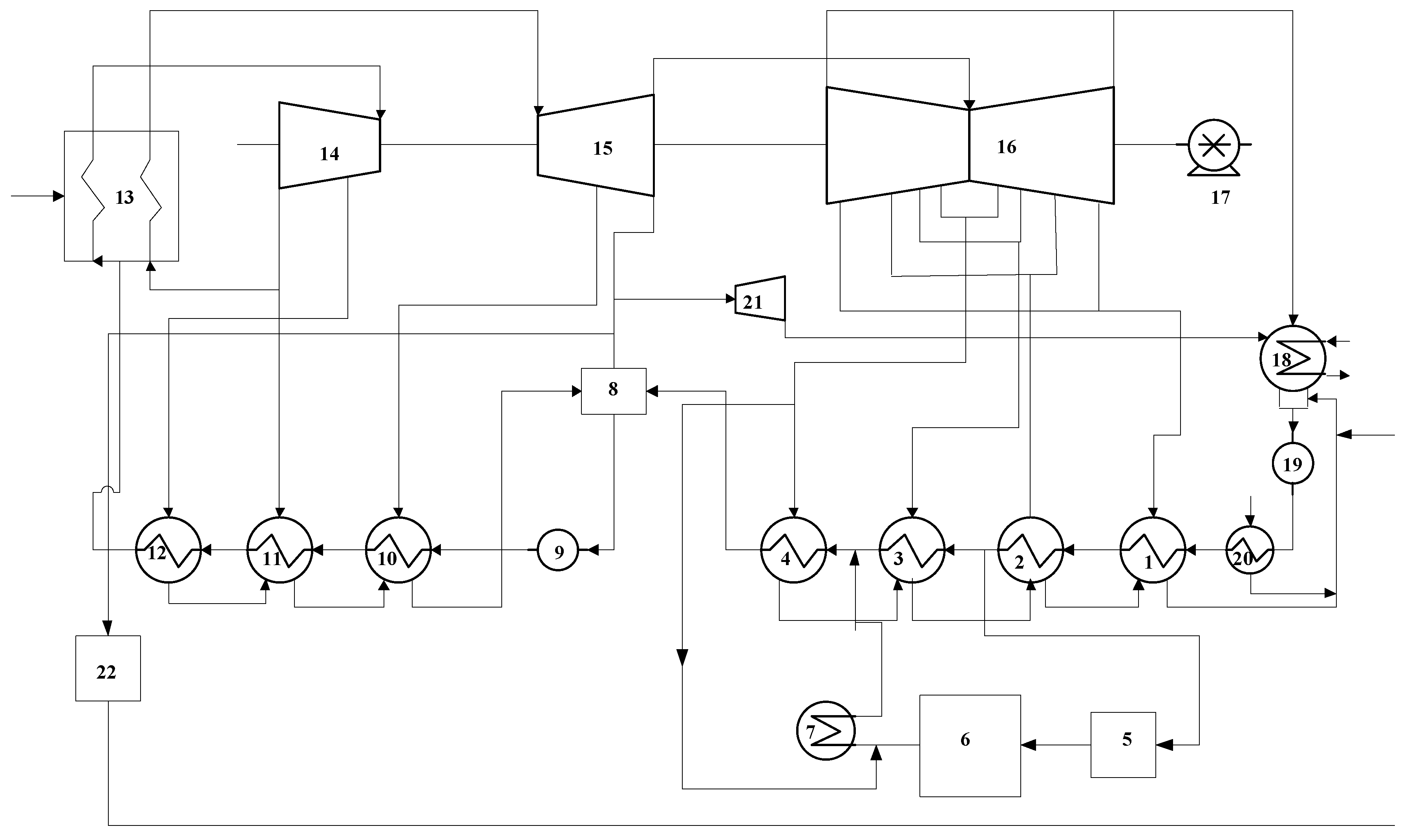
Figure 1. Integration mode of low pressure economizer system and the solar collector field connected in parallel with heater. 1, No. 4 low-pressure heater; 2, No. 3 low-pressure heater; 3, No. 2 low-pressure heater; 4, No. 1 low-pressure heater; 5, low-pressure economizer system; 6, solar collector field; 7, carbon dioxide capture system; 8, deaerator; 9, steam feed pump; 10, No. 3 high-pressure heater; 11, No. 2 high-pressure heater; 12, No. 1 high-pressure heater; 13, superheater; 14, high-pressure cylinder; 15, intermediate-pressure cylinder; 16, low-pressure cylinder; 17, generator; 18, condenser; 19, condensate pump; 20, seal heater; 21, steam turbine; 22, denitration system.
Energies 13 04779 g001
Figure 2. Physical structure of the integration system. 1, No. 4 low-pressure heater; 2, No. 3 low-pressure heater; 3, No. 2 low-pressure heater; 4, low-pressure economizer system; 5, solar collector field; 6, carbon dioxide capture system; 7, No. 1 low-pressure heater; 8, deaerator; 9, steam feed pump; 10, No. 3 high-pressure heater; 11, No. 2 high-pressure heater; 12, No. 1 high-pressure heater; 13, superheater; 14, No. 1 high-pressure cylinder; 15, No. 2 high-pressure cylinder; 16, No. 3 high-pressure cylinder; 17, reheater; 18, No. 1 intermediate-pressure cylinder; 19, No. 2 intermediate-pressure cylinder; 20, No. 1 low-pressure cylinder; 21, No. 2 low-pressure cylinder; 22, No. 3 low-pressure cylinder; 23, No. 4 low-pressure cylinder; 24, No. 5 low-pressure cylinder; 25, steam turbine; 26, denitration system; 27, condenser; 28, condensate pump; 29, generator.
Energies 13 04779 g002
Figure 3. Productive structure of the integration system.
Energies 13 04779 g003
Figure 4. Structural diagram of an energy system.
Energies 13 04779 g004
Figure 5. Variation curves of the collector efficiency and collector area vs. solar irradiance.
Energies 13 04779 g005
Table 1. Composition of the coal.
CarHarOarNarSar
60.402.893.070.870.68
Here, Car, Har, Oar, Nar, and Sar represent carbon, hydrogen, oxygen, nitrogen, and sulfur in the fuel, as received (%).
Table 2. Unit exergy costs of the integration system and original system.
Serial NumberComponentProduct Exergy CostFuel Exergy CostSpecific Irreversible Exergy CostSpecific Negentropy Exergy Cost
Original SystemIntegration SystemOriginal SystemIntegration SystemOriginal SystemIntegration SystemOriginal SystemIntegration System
14DJ3.1963.9312.0862.5241.0261.1530.0840.254
23DJ2.4772.9762.0862.5240.3730.4020.0170.049
32DJ2.3812.7172.0862.5240.2820.0790.0130.113
4LPE-5.795-1-3.596-1.199
5SF-4.538-1-2.651-0.886
6RB-0.952-2.524-0.952--
71DJ2.3542.8652.0862.5240.2560.230.0120.11
8DTR2.2843.0732.0862.5240.1510.4860.0470.062
9FWP2.9433.7122.7283.6260.20.0750.0150.011
103GJ2.3292.7912.0862.5240.2310.2360.0110.031
112GJ2.2142.6792.0862.5240.1220.1370.0060.018
121GJ2.1782.6312.0862.5240.0870.0940.0040.012
13B-SH2.0222.204110.9410.940.0810.264
14HP12.5352.9842.0862.5240.4270.4060.0210.054
15HP22.1852.6652.0862.5240.0940.1240.0050.016
16HP32.1952.6812.0862.5240.1040.1390.0050.018
17RH2.0152.109110.9340.8680.0810.242
18IP12.1852.6782.0862.5240.0950.1350.0050.018
19IP22.1432.6062.0862.5240.0540.0720.0030.01
20LP12.1762.6482.0862.5240.0860.1090.0040.014
21LP22.1452.62.0862.5240.0560.0670.0030.009
22LP32.1442.6152.0862.5240.0550.080.0030.011
23LP42.1742.6332.0862.5240.0840.0960.0040.013
24LP52.4452.9942.0862.5240.3420.4140.0170.055
25BFPT2.7283.6262.0862.5240.6110.9730.030.129
26SG-1.263-2.524-1.263--
27CND0.1030.1082.0862.1290.1020.10400
28CP2.8923.5772.272.7640.5950.7250.0270.088
29GEN2.272.7642.2252.7090.0450.05500
Table 3. Structure of the thermo-economic cost (without considering the investment costs).
Serial NumberComponentProduct Unit Thermo-Economic CostFuel Unit Thermo-Economic Cost’Increase of the Thermo-Economic Cost Caused by IrreversibilitiesIncrease of the Thermo-Economic Cost Cased by Negentropy
Original SystemIntegration SystemOriginal SystemIntegration SystemOriginal SystemIntegration SystemOriginal SystemIntegration System
14DJ97.17996.43563.42861.93131.19728.2752.5546.23
23DJ75.30572.99863.42861.93111.3519.8550.5261.212
32DJ72.3866.6663.42861.9318.5591.9470.3942.782
4LPE-29.404-0-0-29.404
5SF-21.746-0-0-21.746
6RB-85.282-61.931-23.351--
71DJ71.57670.2863.42861.9317.7875.6420.3612.707
8DTR69.44175.38363.42861.9314.58711.9271.4261.525
9FWP89.48791.06682.93888.9596.0921.8420.4570.265
103GJ70.81368.47863.42861.9317.0385.7810.3470.766
112GJ67.3265.73563.42861.9313.713.3590.1830.445
121GJ66.20764.55263.42861.9312.6492.3150.1310.307
13B-SH61.4965.44730.40430.40428.6128.5722.4756.471
14HP177.06173.21463.42861.93112.9929.9640.6421.32
15HP266.42165.3763.42861.9312.8523.0370.1410.402
16HP366.74365.7863.42861.9313.1593.3990.1560.45
17RH61.26462.71230.40430.40428.40426.3812.4565.926
18IP166.44565.68763.42861.9312.8763.3170.1420.439
19IP265.14863.92463.42861.9311.641.760.0810.233
20LP166.17264.95263.42861.9312.6152.6680.1290.353
21LP265.20363.78163.42861.9311.6921.6340.0840.216
22LP365.18464.15663.42861.9311.6741.9650.0830.26
23LP466.11364.58963.42861.9312.5592.3470.1260.311
24LP574.34373.44463.42861.93110.40210.1670.5141.346
25BFPT82.93888.95963.42861.93118.59223.8670.9183.161
26SG-30.973-61.931-30.973-0
27CND3.1322.64663.42861.9313.0983.025-0
28CP87.93887.7369.02367.80618.09317.7740.8212.15
29GEN69.02367.80667.6566.4561.3741.34900
Table 4. Structure of the thermo-economic cost (considering the investment costs).
Serial NumberComponentProduct Unit Thermo-Economic CostFuel Unit Thermo-Economic Cost’Increase of the Thermo-Economic Cost Caused by IrreversibilitiesIncrease of the Thermo-Economic Cost Cased by Negentropy
Original SystemIntegration SystemOriginal SystemIntegration SystemOriginal SystemIntegration SystemOriginal SystemIntegration System
14DJ211.383278.481101.198136.91849.77562.5125.99927.927
23DJ148.653191.59101.198136.91818.11121.7891.2365.435
32DJ140.66193.79101.198136.91813.6564.3050.92512.472
4LPE-155.11-0-0-131.814
5SF-232.249-0-0-97.485
6RB-105.131-136.918-51.625-0
71DJ135.977185.402101.198136.91812.42412.4730.84812.137
8DTR124.902183.184101.198136.9187.31826.3693.3496.838
9FWP188.473256.887156.599230.32911.5034.7691.0741.189
103GJ126.1165.552101.198136.91811.22912.7820.8163.432
112GJ119.104157.721101.198136.9185.9197.4270.431.994
121GJ117.333154.818101.198136.9184.2265.1170.3071.374
13B-SH96.34119.61330.40430.40428.6128.5725.81329.01
14HP1142.51182.477101.198136.91820.72922.0281.5075.915
15HP2119.981159.486101.198136.9184.5516.7150.3311.803
16HP3125.221165.277101.198136.9185.047.5140.3662.018
17RH82.673100.88330.40430.40428.40426.3815.76726.567
18IP1121.429157.37101.198136.9184.5887.3330.3341.969
19IP2119.431158.416101.198136.9182.6163.8910.191.045
20LP1120.629160.697101.198136.9184.1725.8990.3031.584
21LP2122.872162.492101.198136.9182.6993.6130.1960.97
22LP3123.2162.482101.198136.9182.674.3450.1941.167
23LP4125.013162.98101.198136.9184.0845.1890.2971.394
24LP5134.825181.248101.198136.91816.59622.4771.2076.036
25BFPT156.599230.329101.198136.91829.66352.7662.15614.17
26SG-16180.037-136.918-68.477-0
27CND7.3578.12101.198136.9184.9436.68800
28CP178.603237.517129.17169.64133.8644.4681.9299.638
29GEN129.17169.641124.323164.0352.5243.33100