1. Introduction
Overcurrent protection relays play an important role in providing the right conditions for safe and reliable electric drive system operation of mining machines. In accordance with Reference [
1], electric power equipment and installations should be protected against the effects of line-to-earth short-circuits, line-to-line insulation faults and overloads in order to ensure the safety of the mine and its employees. The issue of safety becomes paramount in rooms which are at risk of methane and/or coal dust explosion. To minimize these risks, adequate protections and their settings in electric power installations must be selected in accordance with Reference [
1] and with the principles of mining technology regarding safeguard and protective measures in mining power engineering. Modern microprocessor technology offers great opportunities for wide-range shaping of the time-current characteristics of those protection devices. The selection of appropriate curves of this characteristic must depend on the operating conditions of a given motor. This task is especially difficult in the case of motors which power high-moment inertia devices (e.g., fans). In such cases, the selection of settings must take into account the prolonged starting time and standard requirements. These difficulties are linked with the reliability of conducting a direct start of an electrical motor (with a grid voltage), while protecting the winding of the stator and rotor against the thermal effects of prolonged exposure to the starting current. The thermal effect of this current, which consists of temperature increase of the stator and rotor winding, may cause damage to the motor in case of the malfunctioning of protections or the cooling system. Another case that results in thermal damage to the winding of the motor is inadequate overcurrent protection. Proper selection of time-current characteristics is a complex issue that includes economic factors (linked to the costs of the motor itself, its replacement or repairs, but mostly costs linked to the interruption in operation), technological factors, as well as electric shock, fire or explosive safety issues (e.g., linked to a lack of ventilation). Proper thermal protection of the induction motor is particularly important for motors (and their cable lines) operating in locations at risk of explosion [
2].
Challenges of coordinating characteristics of overload protection are presented in Reference [
3], however this paper puts emphasis on comparing models defined in Reference [
4] with machines and drives supplied from real power networks. This paper evaluates the selection method concerning time-current characteristics in relation to the auxiliary ventube fan motor and the cable network by which it is powered, as an example of a device with prolonged starting time. The following factors were included in the evaluation of the characteristics:
These two factors have a great impact on both the reliability of the motor windings itself and on the reliable operation of overload protection relays. The detailed analysis is given below.
In case of double-cage motors, a protection against too-long or unsuccessful startups should be applied, because not only can a stator insulation temperature rise be an issue, but also the starting (outer) cage can exceed its temperature limit, even if the temperature of stator winding is below the permissible value [
5,
6]. In case of large medium voltage (over 1 kV) motors, this is usually accomplished by a separate protection relay (nowadays usually a part of a multifunction digital relay), but for smaller low voltage motors, it is desirable to use simple overcurrent relays, both for overloads and prolonged startups protection. It can be achieved by a careful selection of their time-current characteristics, but there is no suitable curve in international standards.
Our paper analyzes the high-inertia drive startup process in a comprehensive way—taking into account voltage drops in the supplying network, and is focused on double-cage motor drives. Obtained results are used for design of a quite new time-current characteristic curve, placed between curves defined in an international standard [
4]. This curve allows for a prolonged start, but at the same time, protects the motor windings against small but long-lasting overloads.
Shapes of overcurrent protection characteristics are discussed in References [
7,
8,
9], but they are based on IEEE standards [
10]. Different formulae for the description of these curves are used in the abovementioned papers, while this work uses a formula described in the IEC standards [
4]. The problem of a long-term asymmetry of supply voltages is not considered in this paper, as it is not a significant problem in mine networks (due to the very small number and power of single-phase loads).
The detailed modeling of thermal processes in an induction motor is possible [
5,
6,
11] but it needs an extensive knowledge on particular motor design details (materials and internal structure). This knowledge is usually unavailable from the motor manufacturer, so most overcurrent protective relay solutions are based on a simple first-order model [
12] and its appropriate mathematical description used in standards [
4,
10].
2. Materials and Methods
The starting time is related to the starting current, which is a multiple of the nominal current. Therefore, this state must be treated as improper operating conditions, according to Reference [
13]. The starting process should be as short as possible, but no longer than the time it would take for the motor winding to heat up (due to the starting current) to the maximum permissible temperature for a given class of insulation. An overload-protective device with a properly chosen time-current characteristic should protect against exceeding the maximum permissible temperature (and thus the thermally induced damage of the motor).
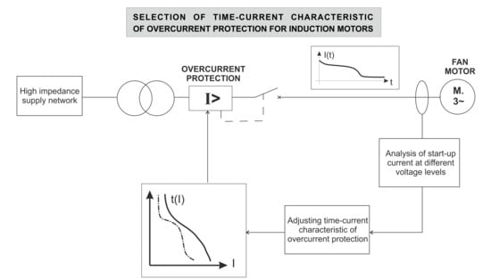
High grid impedance of an underground power network with long cable lines and medium power transformers causes big voltage drops during the flow of the starting current. These voltage drops decrease the voltage level on starting motor terminals and lessen mechanical torque, considerably increasing the starting time. Ventube fan drives specifically are characterized by a large moment of inertia, and in the case of long ventube, they need a long time to fill with air. Thus, a small accelerating torque (at low voltage) causes a long starting time at relatively low starting currents (not detectable by standard overcurrent protection relays set close to locked-rotor currents). This prolonged startup due to the voltage drops problem exists not only in networks with territorially distributed loads, but also in small networks powered from weak (e.g., autonomous) sources [
14,
15]. A mathematical description of the overload protection device characteristics is included in Reference [
4]. The relation between protection delay time, T, and the current value, I/In, of overcurrent protection devices is expressed by the following Equation (1):
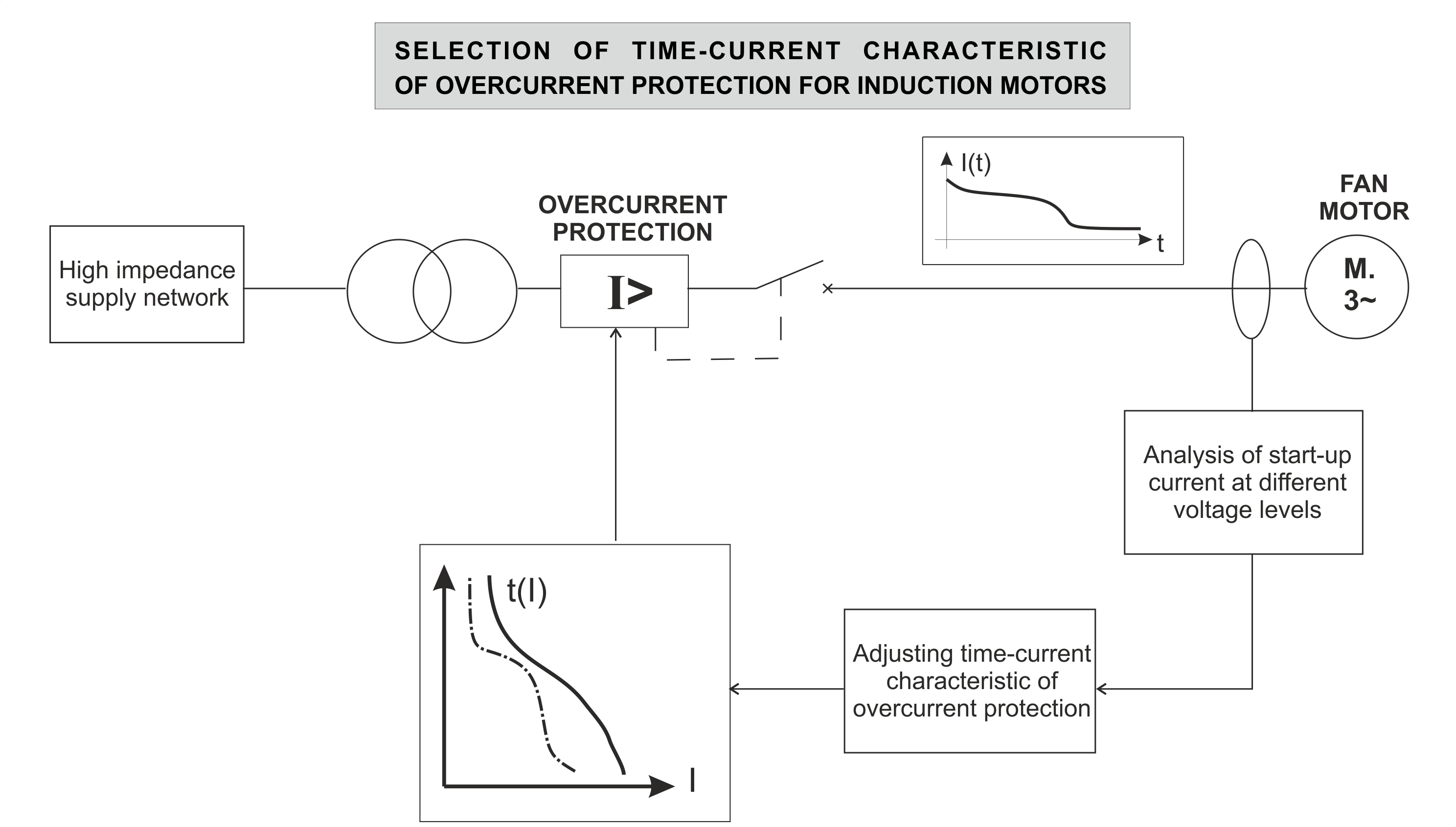
The values of parameters
α and
C included in (1) are shown in
Table 1. This table also includes the values of parameters of (1) for the time-current protection device characteristic proposed by the manufacturer of protection relays for Invertim mining equipment [
16].
Figure 1 below shows the shapes of individual time-current characteristics of overcurrent protections from (1) and values of the parameters included in
Table 1.
Simulations included the study of the WLE-1013/B/E/1 auxiliary axial flow fan powered by a double-cage dSOKg 200L2B-E electric motor.
Table 2 presents the parameters of the motor used in the simulation studies. These motor parameter calculations were performed according to the methodology given in Reference [
17].
The motor parameters have been calculated on the basis of rated data, and as such, they acted as a basis for the design of the speed regulation characteristic, as well as stator current ratio as a function of rotational speed. The obtained speed-torque and speed-current curves indicate sufficient similarity with device characteristics presented by the manufacturer, the Cantoni Group [
18]. These motor parameters were used to evaluate the stator voltage influence on the accelerating time characteristics of the dSOKg 200L2B-E motor,
Me = f(
n),
I1 = f(
n), and the course of the RMS value of stator current in time at the assumed range of stator voltage variation between 0.7·U
n and 1.0·U
n with a step of 0.1·Un in a situation of powering the WLE-1013/B/E/1 auxiliary jet fan with that motor. Many interesting methods exist to calculate the starting time (such as References [
19,
20]). However, those are limited to single cage motors, while this paper focuses on the double-cage motors. Double-cage induction motors simultaneously provide a lower value of starting current and a higher value of starting torque, hence they are widely used in mining. This feature is particularly important in relatively weak power supply networks. In a later stage of the study, calculated series of motor characteristics—where the stator voltage is the main parameter—were used to analyze the selection of time-current characteristics of overcurrent protections for the induction motor in the drive of the axial auxiliary jet fan. The motor was supplied by a flameproof mining mobile transformer station IT3Sm-400/6 (Izol-Plast) and a mining certified cable YHKGXSekyn 3 × 16/15 mm
2 (manufactured by TeleFonika). Parameters of the power supply system are presented in
Table 3 and
Table 4. The medium voltage (6kV) network impedance has been neglected because of its relatively small value (as it is divided by the square of the transformer voltage ratio).
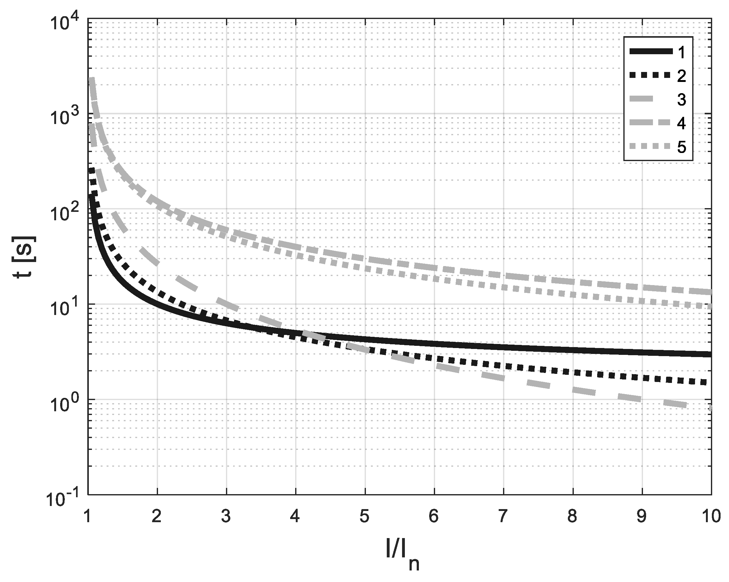
Cable length was calculated to obtain selected values of the motor terminals voltage at startup. The selected cable length values together with corresponding voltage levels are presented in
Table 5. These calculations were done using a scheme of voltage divider composed of a supply system (transformer and cable) and a load (motor).
Figure 2 below shows the relationship between the startup voltage level and cable length in the whole analyzed range. Selected points were marked with circles. The number of these points was limited for the sake of clarity.
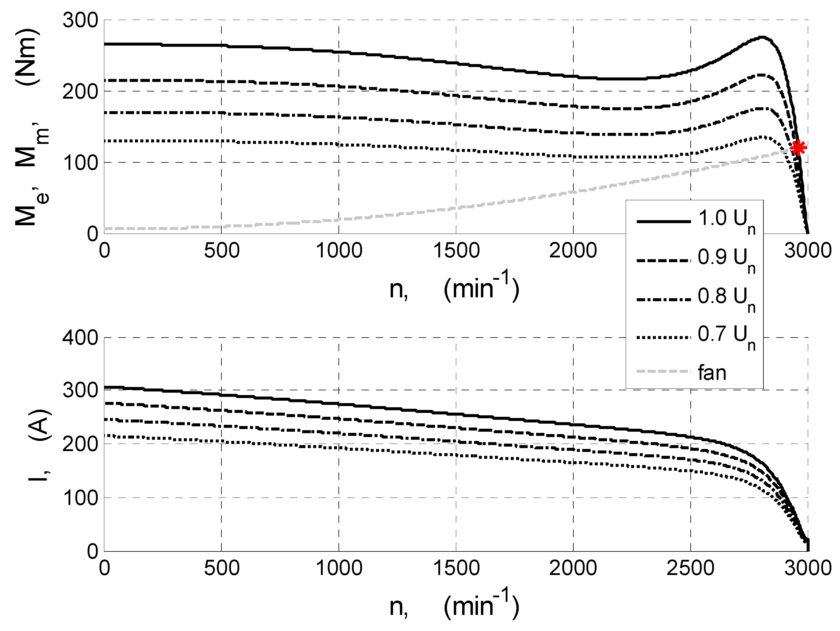
Figure 3,
Figure 4 and
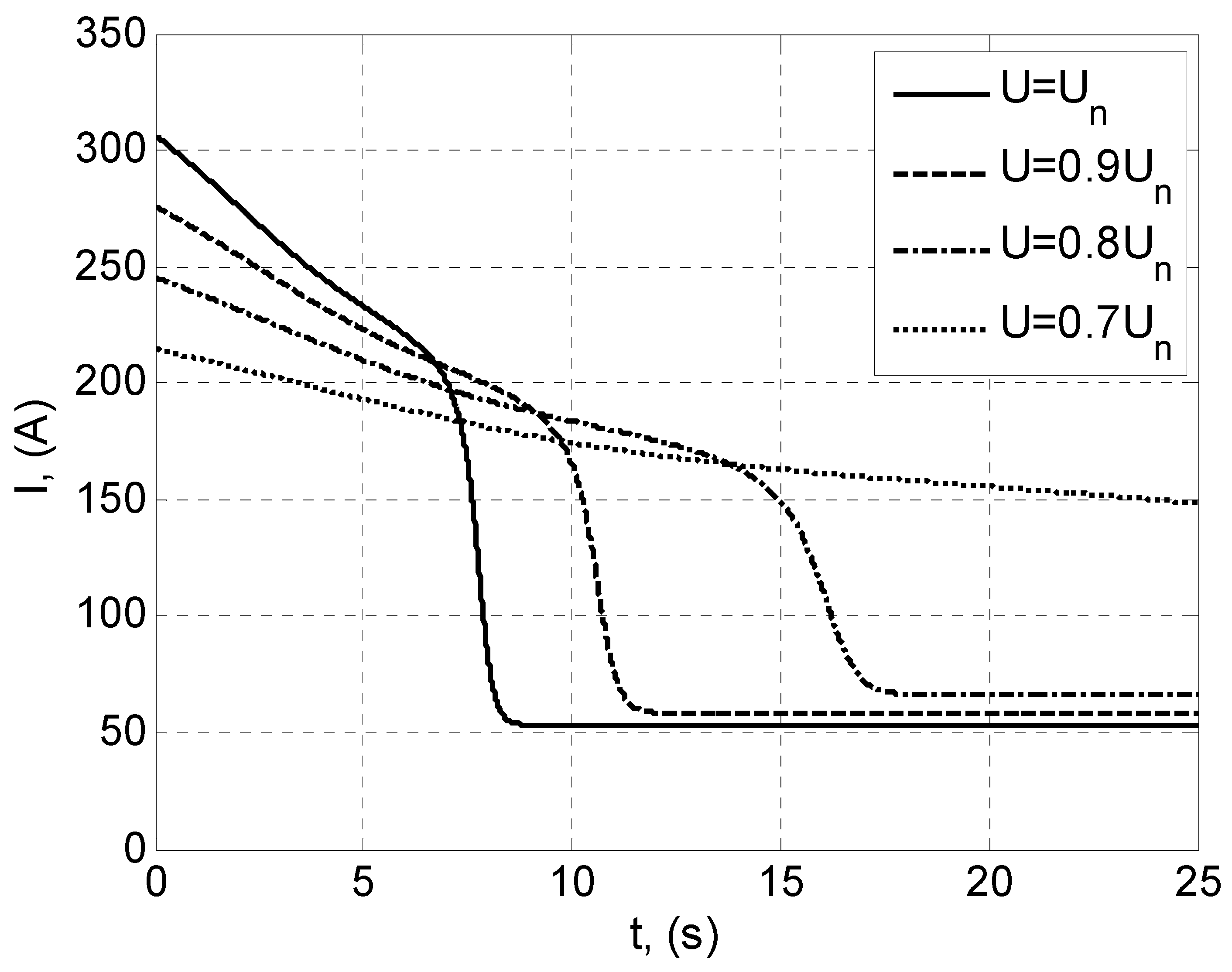
Figure 5 show the influence of the stator voltage on the mechanical characteristics of the motor driving the auxiliary jet fan, on the stator current, as well as on the rotational speed during starting of the motor.
As can be seen in
Figure 4, the lowest momentary value of accelerating torque occurs at the lowest voltage level, i.e., 0.7·U
n, which results in the inability to conduct the starting process in a time shorter than 25 s (
Figure 4 and
Figure 5). In this situation, the motor current reaches a RMS value which is many times higher than the nominal one and in that time, it will not be reduced to a value close to the nominal (
Figure 5).
Reaching a stable motor operating point (dn/dt = 0) is possible for stator voltage equal to at least 0.8·Un, while the starting time is in a range between 8 (for U1 = Un) and 17.5 s (U1 = 0.8·Un).
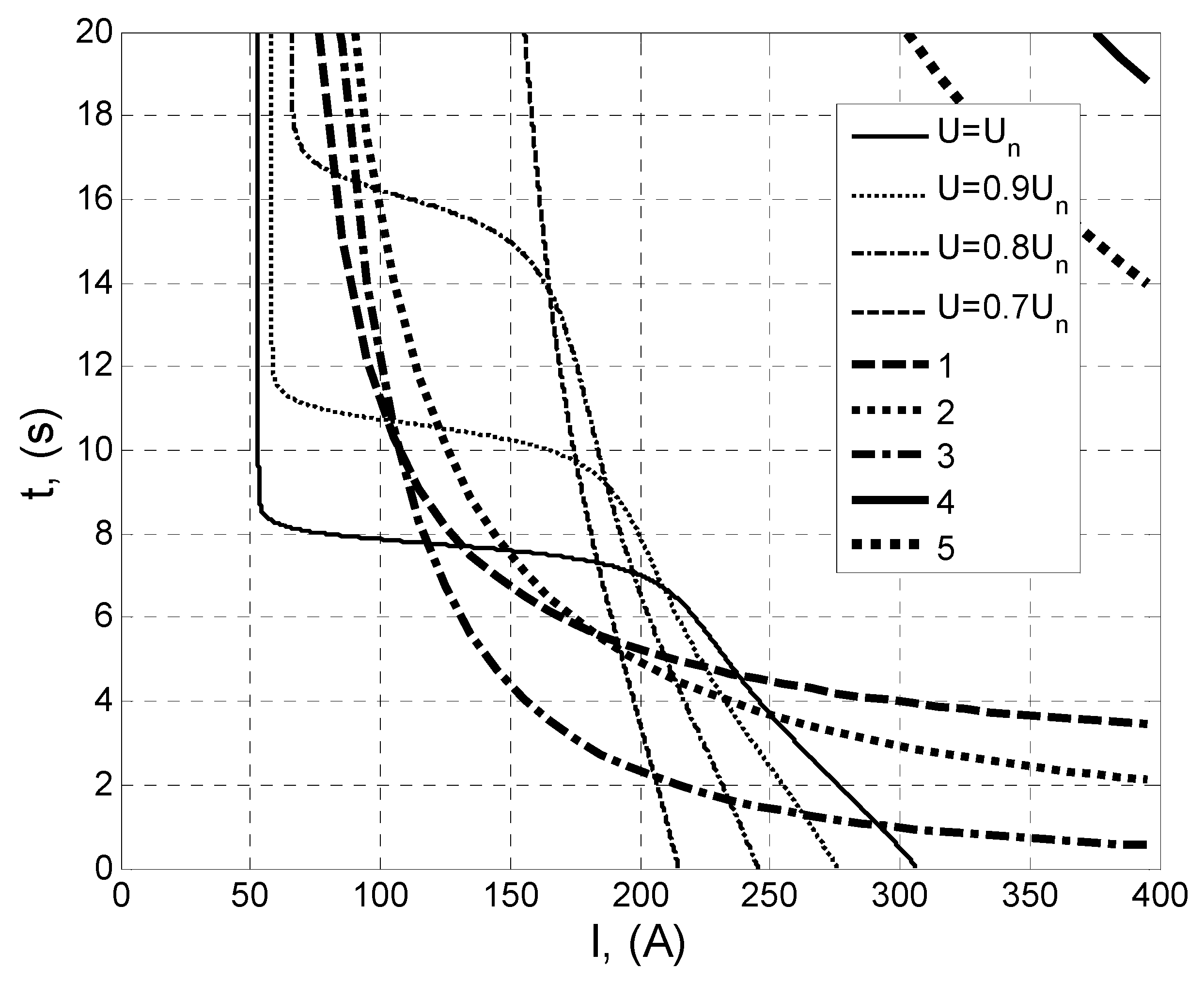
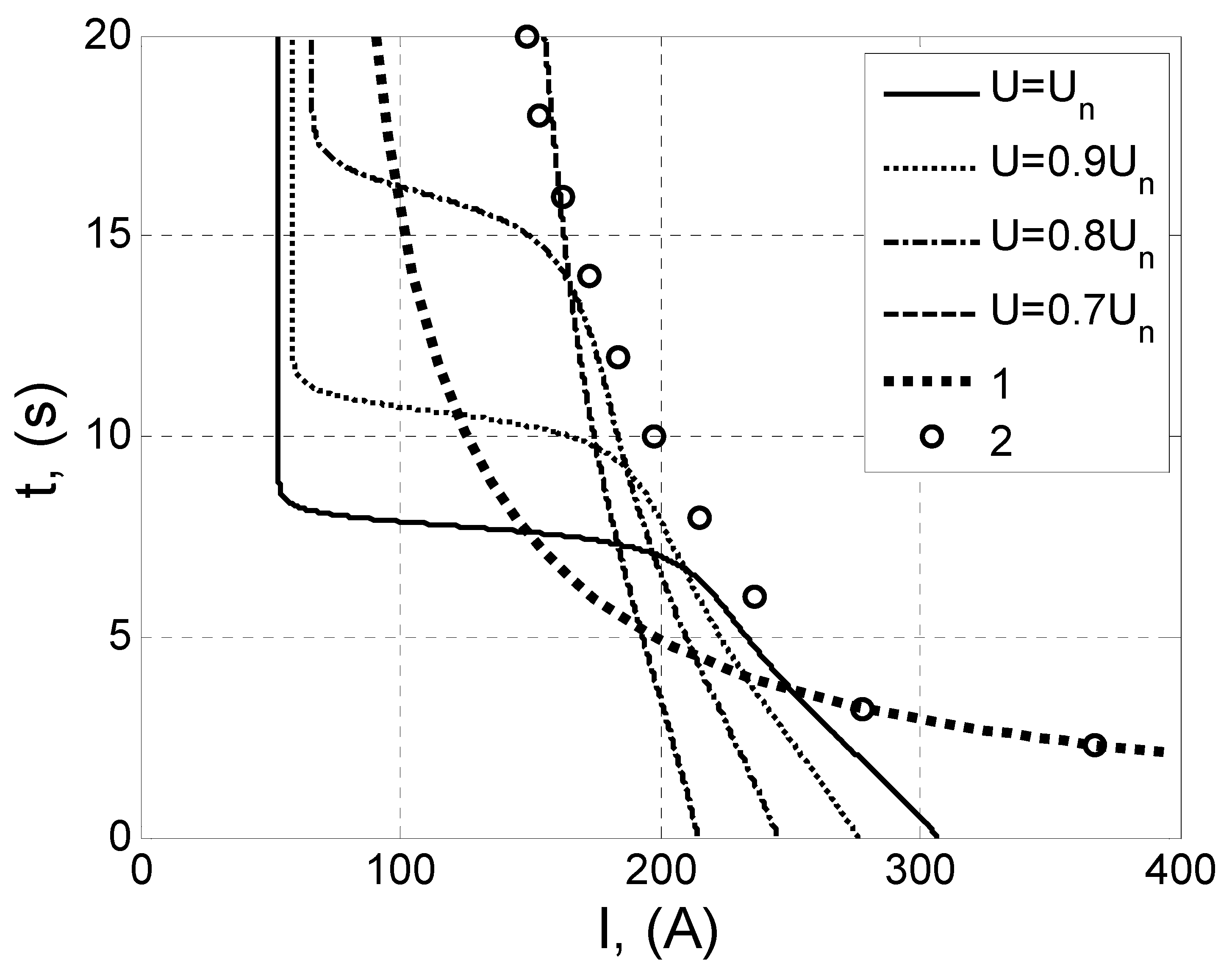
Overcurrent protection should protect the motor (and supplying cable) against the effects of overcurrent, allowing for the starting of the device. This is not an easy task in case of drives with prolonged starting times, which may be observed by matching courses of stator currents from
Figure 4 with time-current characteristics of the protections (
Figure 6).
The point of intersection between the time-current characteristic of the protection and the current course curve of the motor is the time at which the motor shuts off prematurely, which makes it impossible to finish the starting process of the drive.
The selection of overcurrent protection settings in accordance with Condition (1) indicates that the choice to use a protection with characteristics consistent with Reference [
4] was formally correct.
But, as can be seen in
Figure 6, protections with characteristics of Standard Inverse, Very Inverse and Extremely Inverse, set in accordance with Reference [
21] to a value of 1,1·
In, will end the starting process after ca. 3.8 to 5 s, regardless of the voltage value on the motor terminals. When using protection with characteristics of Long Inverse or Invertim, starting the motor will be possible for each analyzed voltage. However, the efficiency of the protection might prove insufficient in case of a failed start, which occurs at voltage equal to 0.7 U
n, or in case of small but long-lasting overloads.
3. Results
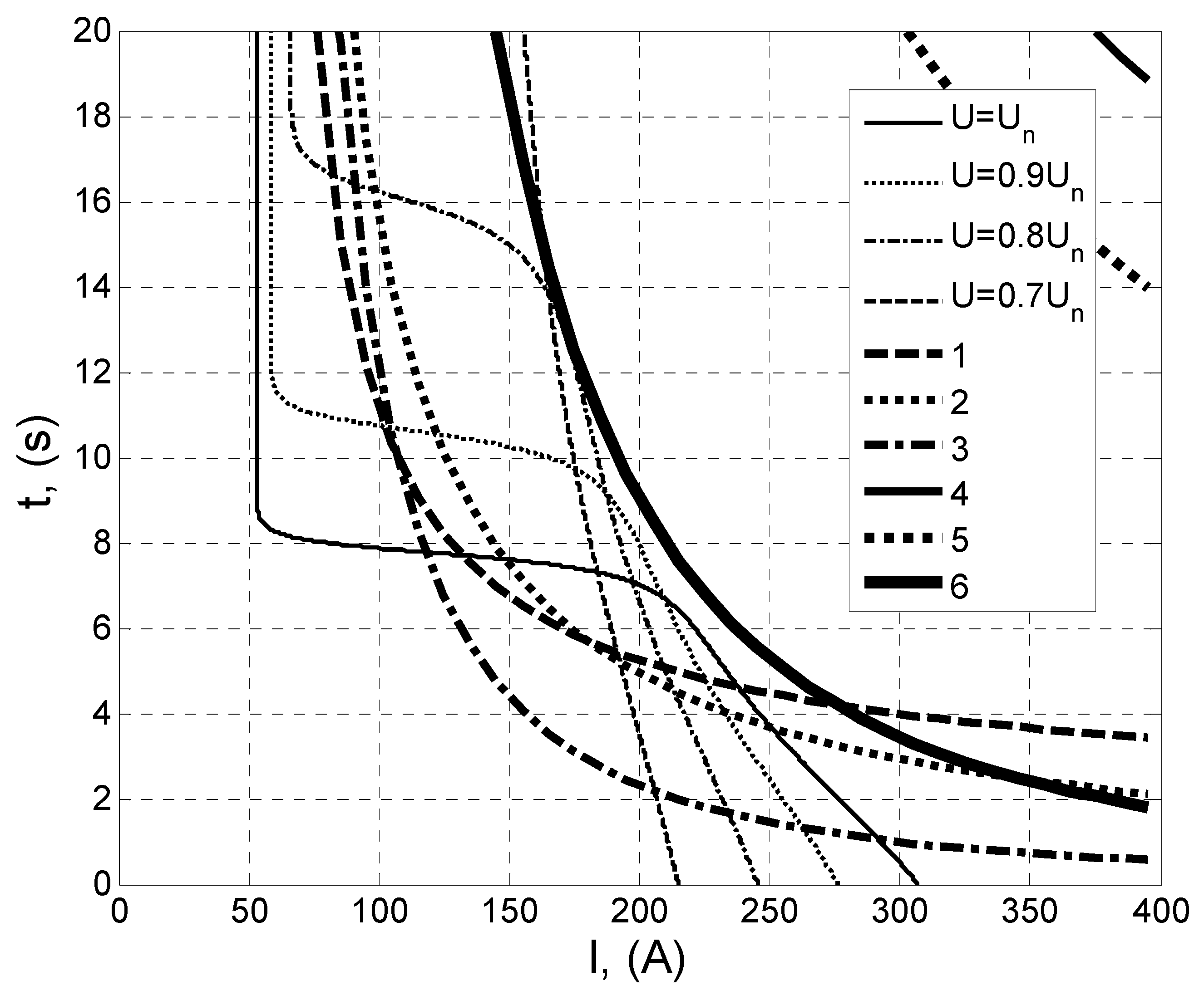
From the results of the simulation studies, it can be concluded that there is a need to design an intermediate protection characteristic situated between Extremely Inverse and Invertim. In relation to the courses of starting currents from
Figure 6, depicting a situation where the stator voltage of the motor is in range (0.8 ÷ 1) U
n, the parameters
α and
C of Equation (1) were identified in order to designate a characteristic of an overcurrent protection with features intermediate between protections with Standard Inverse characteristics and those with Invertim characteristics. It was assumed in a simplistic manner that the winding temperature in induction devices at starting time up to 20 s will not exceed the permissible temperature for a given class of insulation. In such a situation, the investigated characteristic should run above the characteristics of starting currents for the assumed voltage range, and its shape should be as similar as possible to the Extremely Inverse characteristic. The values of designated parameters of Equation (1) describing the investigated time-current characteristic are
α = 2.3 and
C = 178, respectively. The course of the characteristic with designated parameters
α and
C is marked with the number “6” in
Figure 7. As can be seen in that figure, the protection with the characteristic marked as “6” allows for the starting of the auxiliary ventube fan motor in the stator voltage range (0.8 ÷ 1)·U
n. At the same time, the protection with this characteristic ensures safety from the effects of a failed starting process, so, in the case where U = 0.7·U
n. It must be noted that while this protection is not as effective as devices with the characteristics of Standard Inverse, Very Inverse and Extremely Inverse, it is better than protection devices with Long Inverse and Invertim characteristics. The detailed methodology is described below.
We attempted to determine a new time-current characteristic of the overload protection, as none of the standard characteristics of the overload protection given in Reference [
4] take into account the specific supply and operation of mining machines with extended start-up times. The following assumptions were made to identify the Equation (1) parameter values:
For large current values (above 5 In), the characteristic should have a shape similar to the curve “2”, i.e., Very Inverse.
The course of the characteristic should enable starting the machine in voltage conditions (0.8 ÷ 1.0) Un, i.e., the protection characteristic should not intersect the motor time-current characteristics, which reach the steady state in a time shorter than the maximum value (20 s).
The characteristic should be modeled with regard to the shut-off time of a motor supplied with 0.7 Un voltage, in a time not longer than the maximum value of 20 s.
The identification of the Equation (1) parameter values was carried out for the data points specified in the characteristics of
Figure 8 that fulfill the above assumptions. Data point values for currents above 3.2
In are arbitrary so that the third assumption is met.
In order to calculate the values of the Equation (1)
α and
C parameter values, the Equation was transformed into the following form (2):
where
T(k)—data points of the response time values,
—calculated values of currents for given times T(k) and values of coefficients α and C.
k = 1, 2, …, N,
N—number of data points.
Subsequently, iterative computer calculations were carried out to determine from the Equation (2) the values of the
I(
k) currents with given values of time
T(
k) for the parameters
α and
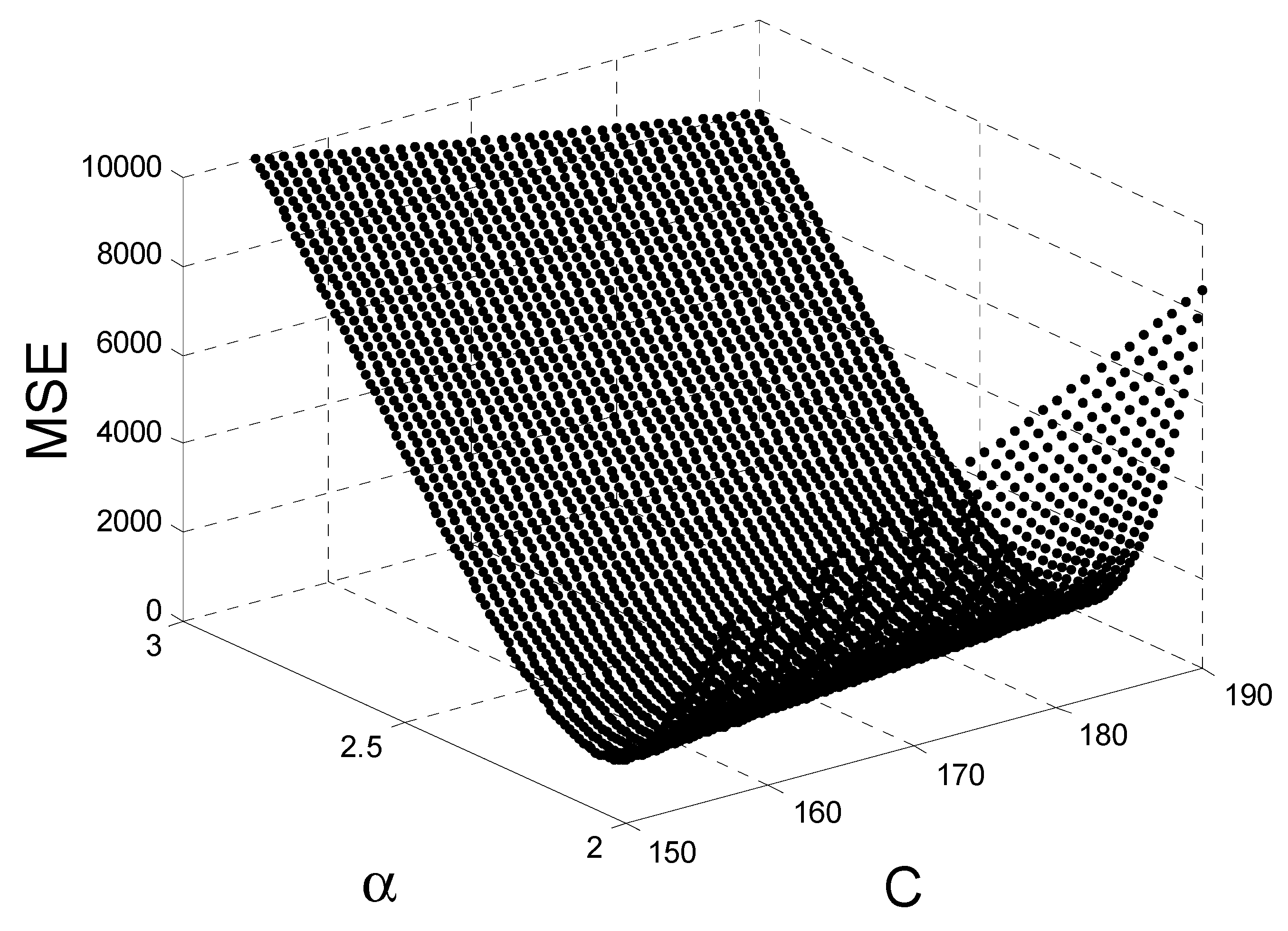
C, which were selected from the ranges 〈2.0, 3.0〉 and 〈150, 190〉, respectively. The identification task was therefore reduced to determine such values of parameters
α and
C that would minimize the accepted criterion in the form of the mean square error (MSE). This condition can be written as follows (3):
where:
I(
k)—data points of current values (from
Figure 8) for the corresponding
T(
k) time values.
The dependence of MSE value surface on the parameters
α and
C in the whole analyzed area is shown in
Figure 9.
In order to verify the results obtained from the identification of the parameters of Equation (1) described above, a second method was used to determine these constants. Equation (1) can be transformed into the following form:
This formula represents a linear function. In such a situation, the
α coefficient at a given
C (from the range as in
Figure 9) can be determined either by linear regression, or by the method of least squares. The value of Criterion (8) is then calculated for the obtained data. Using Equation (4) significantly reduces the calculation time.
If Equation (4) transforms due to α to the form:
then its value for a given
C should be constant for each point
k. In fact, there are small differences for different points, so it can be determined as an arithmetic mean for a given value of
C.
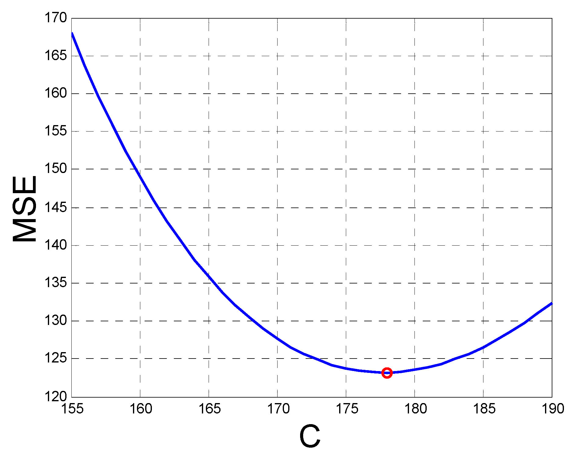
The performed identification calculations using the Formula (6) and Criterion (7) for
C in the range as shown in
Figure 9 gave identical results as the method described above—using Criterion (3). The dependence of the criterion on the
C parameter for different
α values obtained in this situation is shown in
Figure 10.
Minimum MSE values were obtained for α = 2.3 and C = 178, which is exactly the same as the method based on Formula (2) and Criterion (3). The values of Criteria (3) and (7) are 123 in both cases.
The protection device with the proposed “6” characteristics exhibits features which are intermediate between protections with Very Inverse characteristics and those with Invertim characteristics, while the shape of this characteristic is similar to Extremely Inverse characteristics, which is consistent with the previous assumptions. In more complex operating conditions (e.g., consecutive starts) and using a more complicated model description, characteristics design can be made using more complicated and much more time-consuming evolutionary computations—like Particle Swarm Optimization, as in Reference [
22].


