Abstract
In wind power systems, LCL inverters have technical problems. First of all, they are non-linear systems and are no longer adapted to the superposition principle; secondly, the coupling is great; finally, it is easy to be interfered by the outside world, and the interference mainly comes from voltage fluctuations and nonlinear loads on the grid. Therefore, it is difficult to control the output result, and then the improved linear active disturbance rejection control (LADRC) is applied. The main improvement of the improved LADRC lies in the linear extended state observer (LESO). Introducing the total disturbance differential signal in LESO, and in order to improve the ability to suppress high-frequency noise, a series of first-order inertia link was applied. The analysis method in this article is mainly frequency domain analysis, under the condition of obtaining LADRC closed-loop transfer function and frequency band characteristics, theoretical analysis of LADRC tracking estimation ability, disturbance suppression ability, and stability. A large number of experimental simulation results verified the superiority of improving LADRC. The main manifestation is that the improved LADRC not only has a fast response speed but also has a strong ability to suppress disturbances and has a good noise suppression effect in high frequency bands.
1. Introduction
Due to the necessity of energy and the exhaustion of fossil energy, renewable energy had received people’s attention. Therefore, more and more wind power is applied to modern power systems. Because the inverter with LCL filter is usually used in the grid interface. Therefore, the instability of the system is increased. When wind power grid-connected inverters are affected by grid voltage fluctuations and related loads, they will cause Direct Current (DC) bus voltage fluctuations, which will have a major impact on the stability of the entire wind power system [1,2,3]. In order to suppress the fluctuation of the inverter DC bus voltage. Literature [4] applies a master-slave control strategy to improve the stability of the DC bus voltage. The control system between the grid side and the machine side is coupled with each other; therefore, it is difficult to design. In reference [5], the power feed-forward control strategy is used to stabilize the DC bus voltage in the shortest time when the DC bus voltage fluctuates in a large range. However, there is a problem that the DC bus voltage fluctuates in a large range under transient conditions. Literature [6] proposed the application of nonlinear active disturbance rejection control, but the design is cumbersome and has many parameters. In reference [7], the differential term of output voltage error is added, so the bandwidth of linear extended state observer is increased, and the anti-interference ability of the system is improved. However, the parameter of linear extended state observer (LESO) is approximately doubled, which makes the system tuning more difficult.
Professor Han Jingqing proposed the active disturbance rejection control (ADRC) strategy. It can equate the internal and external disturbances in the system that is different from the integral series type to the total disturbance of the system, and use the extended state observer (ESO) to estimate and compensate the total disturbance. Reference [8] shows that when the ADRC is applied to wind power inverter. It can have strong control effect on the complex system with strong coupling, multivariable and nonlinear. In reference [9], the linear active disturbance rejection control (LADRC) is proposed by connecting the controller parameters with the bandwidth, which solves the problem of numerous parameters of traditional nonlinear active disturbance rejection control Strategy. In reference [10], an improved LESO is proposed. The new state variable is the differential of the total disturbance of the system. By observing the change trend of the total disturbance, an early effective correction signal is generated, which can effectively increase the bandwidth of the LESO and enhance its dynamic observation ability. Literature [11] proposed a reduced-order extended state observer (RESO) for parallel inverters, which can effectively improve the stability of the system.
In this paper, the DC bus voltage is used as the control object, and the application of LADRC in the outer voltage loop is constructed. Firstly, it introduces the design and configuration method of traditional fourth-order LADRC. Secondly, the parameters are improved by referring to the method of lead and lag, therefore improving the tracking performance. Finally, the first-order inertial link is introduced into the linear expansion state observer so that the system avoids the introduction of noise as the observer’s bandwidth increases, and then realizes the improved fourth-order LESO. Through reasonable configuration of poles, no adjustable parameters are added, combined with the log frequency curve diagram. The dynamic performance and immunity of the new LADRC and the traditional LADRC are compared and analyzed. The stability conditions of the new LADRC are given by algebraic criteria. Through the frequency domain analysis method, the traditional LADRC and the improved LADRC are compared and analyzed in terms of dynamic and steady state performance and anti-interference ability. Moreover, the stability conditions of the improved LADRC are given. The performance of the two control strategies was further verified by simulation and experiment.
2. Grid-Side Inverter Modeling and Its Traditional LADRC Design
2.1. Wind Power Filter Modeling
Figure 1 is the control block diagram of the LCL inverter in the wind power system [12]. is the filter inductance on the inverter side, is the resistance on the inverter side. and are respectively the filter inductance and the filter parasitic resistance at the grid side. is the filter capacitance; is damping resistance; is the three-phase grid voltage of LCL inverter, is the three-phase grid-connected current of LCL inverter.
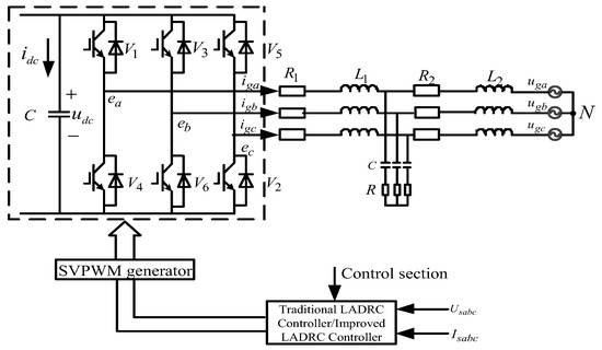
Figure 1.
Block diagram of the grid-side converter with LCL filter.
According to Figure 1, the mathematical model of the grid-side filter under park transformation can be obtained [13]:
In the above formula: , and , represents the and axis components of inverter current and grid side current respectively.
2.2. Traditional LADRC Structure Design
LADRC is composed of three parts: linear extended state observer (LESO, for the observation of total disturbance), tracking differentiator (TD), and linear state error feedback (LSEF) [14]. As shown in Figure 2, the role of LESO is to realize real-time estimation and compensation of external and internal disturbances. The main function of LSEF in LADRC is to generate error and differential signals, and to convert them into error integral signals, and, finally, to form control rate. The control rate is the error differential signal and error signal combination of several signals. The function of TD in the linear controller is to improve the quality of control and simplify the design of the controller. Its working principle is to extract the continuous and differential signals in the measurement signal from discontinuity or random noise.
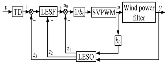
Figure 2.
This is traditional linear active disturbance rejection control (LADRC) structure diagram.
It can be deduced from Equations (1)–(3) that:
In the above formula:
As can be seen from Equation (4), the mathematical model of the wind power filter is a third-order system, then the controlled object:
In the formula, and are output and input respectively, and is disturbance. , , and are all unknown, and the part is known (the known part is marked as ), then Equation (5) can be written as:
In the above formula:
The above formula is the total interference including external interference and internal interference. Select the state variable: , , , , then the variable is the extended state including disturbance. Equation (5) is transformed into a continuous extended state space description:
In the above formula:
The corresponding third-order continuous LESO is:
Among them, , , , and are the system output observed by LESO and its differential and total disturbance; , , , and are the coefficients of the state observer respectively. Selecting the appropriate observer gain allows LESO to track various variables in the system (5) in real time, namely , , , .
Take the control signal as follows:
Without considering the error of to estimation, the system (3) can be reduced to a double integral series structure.
It can be understood from Equation (4) that the LCL filter in the wind power system is third-order; according to the principle that LESO adopts a higher order, the full-order LESO is used, so in the LADRC, the LSEF can be designed as [15]:
In the above formula: is the given signal, , are the controller gains, according to Equations (11) and (12), the closed-loop transfer function of the system can be obtained as:
The traditional fourth-order LESO [16,17,18,19,20] has two inputs and four outputs , , , , where is the second derivative of the output of the controlled system, and is the observed total disturbance signal. According to Equations (9), (10), and (12), it can be seen that the traditional fourth-order LADRC is shown in Figure 3:
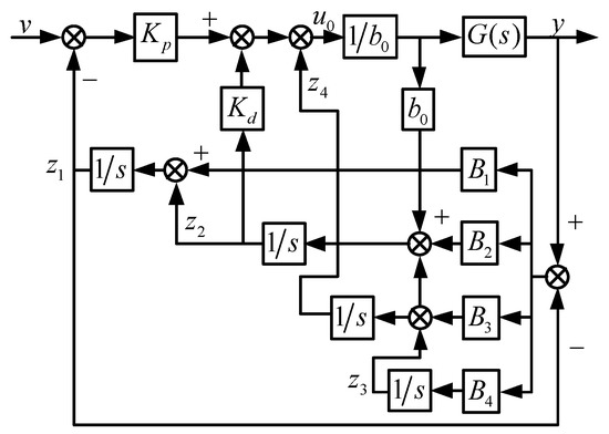
Figure 3.
Linear active disturbance rejection controller structure diagram.
According to the adoption principle of LESO, since the LCL filter in the wind power system is third-order, the LESO of the above system should be fourth-order, so its characteristic equation is:
According to the pole configuration method [21], the traditional LESO in Equation (14) is configured as follows:
For the convenience of analysis, Equation (13) can be simplified to:
According to the literature [22], the parameters of the above formula are:
In the above formula: is called the observer bandwidth, is called the controller bandwidth, and is the damping ratio. Therefore, the configuration of LADRC control parameters is simplified to the selection of the observer bandwidth and the controller bandwidth and the appropriate selection of the gain can make the system stable.
3. Analysis of Convergence and Filtering Performance of Traditional LESO
The core of the LADRC technology is the LESO, and LESO has little dependence on the model of the system [23], the main point is whether the tracking ability of LESO can meet the technical requirements, because it will affect the performance of the active disturbance rejection control. Therefore, this section analyzes it first.
Convergence and Estimation Error Analysis of Traditional LESO
According to Equations (9) and (14):
Let the tracking error , , we can get:
Let , and according to Formula (6), there are:
Then there are:
Considering the typicality of the analysis, both and take a step signal with amplitude , , , then the steady-state error can be obtained:
The above formula shows that LESO has the following characteristics and has good performance in convergence and error estimation, and it can complete the estimation of system state variables and generalized disturbance without error.
It should be added that when in Equation (9), the response of Equation (18) to step signal is as follows:
Carrying out the reverse pull transformation, we can get:
It can be seen from the above formula that its tracking ability is better. In the fourth-order LESO, there is overshoot in the tracking process of to . The important reason is that the observation signal has a step mutation, which causes the estimation error to increase suddenly, so that the observer output has a very obvious peak. The overshoot described above is a common phenomenon in linear observers because it is its essential feature. It is easy to know from the above analysis that the output of linear observer in the fourth-order linear auto disturbance controller will not affect the overshoot no matter how much bandwidth is selected. In general, the speed or position of the controlled target will not change suddenly, which is due to the inertial effect in the dynamic system, so the overshoot of the observed signal in the dynamic index of the linear active disturbance rejection controller does not appear very serious. However, in one case, the reversal does occur, when the fourth-order LESO is used as a differentiator alone. This will cause serious distortion of the observed signal due to its overshoot, since the use of LESO as a differentiator alone is equivalent to giving the system a pulse response signal. Therefore, it is very important to select a new method, so the application of a perturbation parameter method has a good effect in restraining signal distortion. It can be seen from the formula that the observer bandwidth will affect its tracking speed. Although the response is faster with the increase of observer bandwidth, the ability to suppress high-frequency noise is also declining. Therefore, the ability to suppress noise will be analyzed in the following.
According to Equations (20) and (23), the transfer function of the traditional fourth-order disturbance observation is as follows:
The frequency domain characteristic curves of are obtained as shown in Figure 4. It can be seen from the figure that as the observer bandwidth increases, the response speed of the system is also rapidly increasing. However, the effect of noise amplification in the high frequency range is also obvious. This is because the gain increases with the observer bandwidth in the high frequency band.
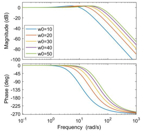
Figure 4.
Traditional linear extended state observer (LESO) disturbance transfer function amplitude-phase curve.
4. Improved Fourth-Order LESO Analysis
Core part of the LADRC is the LESO. Its aim is to solve the core problem of the disturbance observation of LESO in anti-disturbance. Its working principle is to connect uncertain external disturbance objects in series with integrators to achieve the purpose of control. Therefore, LESO has very good robustness and adaptability.
4.1. Improved LESO Structure Design
In the traditional LESO, the series lead lag correction is used; it cannot only improve the stability margin of the system, but also suppress noise in the high frequency range. The improved LADRC structure is shown in Figure 5.
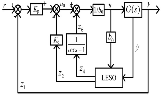
Figure 5.
Structure diagram of improved LADRC.
Based on the above structure diagram analysis, the improved LESO state space is:
In the formula, , , , are the observer gains. If the observer is chosen reasonably, the system motion state can be observed effectively. Among them , , , .
The structure of the improved second-order LADRC control system can be seen from the above equation, As shown in Figure 6.
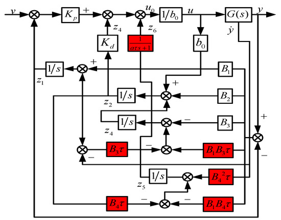
Figure 6.
Structure of improved LADRC control system.
The transfer function can be obtained from Equation (25):
The above formula is as follows:
According to Equation (31), the disturbance observation transfer function of the new LESO can be obtained as:
According to the pole configuration method, configure the new LESO as follows:
According to Formula (30):
Let the tracking error to get:
Let , and according to Equation (9), there is:
Among them:
Then there are:
Due to the typicality of the analysis system response, the signal taken by , is a step signal and the amplitude is , if the signal is set as , , then the error in steady state is:
In terms of convergence and estimation ability, LESO has good performance characteristics, and can complete the estimation of system state variables and generalized disturbances without errors, as can be seen from the above formula.
Figure 7 shows two types of LESO disturbance transfer function amplitude-frequency characteristic curves. Comparing the two types of LESO, it can be seen that the observer bandwidth of the improved LESO increases significantly. The phase lag in the middle and high frequency bands is effectively alleviated, and the noise suppression capability is also greatly improved.
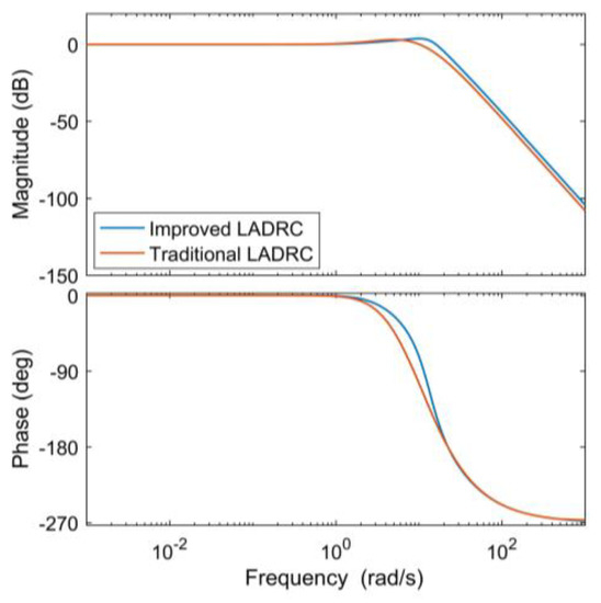
Figure 7.
Comparison of traditional and improved LADRC disturbance observation capability.
4.2. LESO’s Frequency Band Characteristics and Filtering Performance Analysis
In this paper, the noise of observation y is mainly considered, the influence of input disturbance of control quantity on improved LESO, according to the equation, the transfer function of the observed noise is:
where and are:
Take where and are constants and the range is [0, 1].The frequency domain characteristic curve is shown in Figure 8, under the condition that the observer bandwidth gradually increases, the rapidity of the system’s response is also gradually increasing, but the effect of high-frequency noise amplification is becoming more and more obvious. The main reason is that the gain of the high frequency band is gradually expanding.
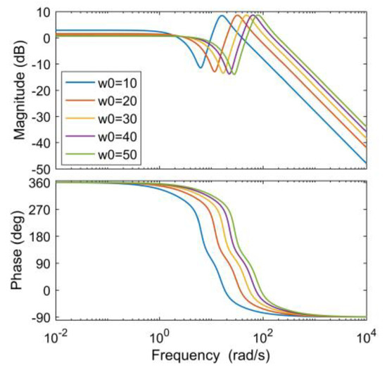
Figure 8.
Frequency domain characteristic curve of observed noise.
From the same reasoning above, the transfer function with respect to the input disturbance is:
Let , to know the frequency characteristics, as shown in Figure 9, different from the above Figure 8, with the increase of the observer bandwidth, the phase lag decreases gradually, as far as the tracking signal is concerned, the fourth-order LESO has a good suppression effect on the input disturbance.

Figure 9.
The input end perturbs the amplitude-frequency characteristic curve.
5. Analysis of the Stability and Anti-Interference Characteristics of LADRC
The previous analysis has analyzed how to efficiently promote the observation ability of the linear observer in terms of disturbances. The method is mainly to add the first-order inertial link and the observation total disturbance differential, and to also analyze the performance of the band characteristics and noise suppression of the linear observer. This section focuses on the analysis of the frequency band characteristics of the linear active disturbance rejection controller, based on the analysis in the previous section. The main entry point is to discuss the influence of the linear observer bandwidth and the controller bandwidth on the system control performance, and the simulation theory to analyze the anti-interference ability of the system in terms of improved LADRC.
5.1. Transfer Function of Second Order Object LADRC
According to Equations (10), (12) and (35)–(37), it can be concluded that:
Substitute the Equations (35)–(37) to get:
The system structure diagram can be simplified to Figure 10 by Equations (50) and (59):
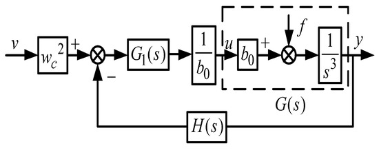
Figure 10.
Simplified system structure diagram.
In the figure, and are respectively:
In the above formula:
According to the above Equation (23), the model of the controlled object is:
Combined with Figure 10, the closed-loop transfer function of the system can be obtained as follows:
It can be obtained from the above formula:
In the above formula:
Obviously, from the above Equation (60), the two items of tracking and disturbance constitute the output of the system. The improved LADRC has good changes in tracking performance and dynamic observation performance. The traditional LADRC closed-loop transfer function obtained in literature [8] is compared with the improved LADRC closed-loop transfer function. The disturbance term and the output term has changed. This kind of phenomenon verifies that the above performance has been improved. When ignoring the estimation error of to , the system (60) can be simplified so its output only contains the tracking term. At this time, the system control performance is only determined by and has nothing to do with . With the increase of the linear expansion observer , the dynamic performance index tracking is also well improved, and there is no overshoot during the tracking process. Dynamic observation error is the main analysis and research element in this article, which will cause disturbances in the output, and it is a very important element that will change the control performance of the system. As mentioned above, the external disturbance and the uncertainty in the system constitute the generalized disturbance; the gain uncertainty of the control input and the uncertainty of the model constitute the internal uncertainty of the system. Therefore, in the following, we will analyze the characteristics of linear active disturbance rejection controller’s ability to suppress external disturbances and stability.
5.2. Analysis of Anti-Interference Characteristics of Improved LADRC
It can be seen from the formula that (60) the influence of the disturbance term is related to and . Choose , to get the frequency domain characteristic curve as shown in Figure 11a. The frequency domain characteristic curve when , is shown in Figure 11b. It can be seen from the figure that increasing and can reduce the disturbance gain and increase the system’s anti-disturbance ability.
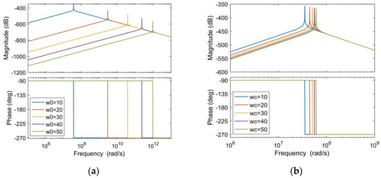
Figure 11.
This is (a) Amplitude frequency characteristic curve of the disturbance term ( change); (b) Amplitude frequency characteristic curve of the disturbance term ( change).
In particular, taking the disturbance as the unit step signal, the output response can be obtained according to Equation (60):
The inverse transformation of the above pull type can be obtained:
In the above formula, are all greater than zero and the value of the above formula tends to zero when t tends to infinity. That is, when the external disturbance is a step signal, the steady-state output of the system is zero. According to Equation (68), it can be seen that increasing the observer bandwidth and the controller bandwidth can make decay relatively quickly, and the transition time is also shorter (the system recovery time is short). This phenomenon indicates that there is an improved type LESO is relatively strong in anti-interference ability.
5.3. Analysis of Improved LADRC against Grid Voltage Disturbance
In the wind power inverter system, the main disturbance is on the side of the grid, so it is very important to analyze the improved linear active disturbance rejection controller to suppress the disturbance inside and outside the system. The system structure diagram is shown in Figure 12.
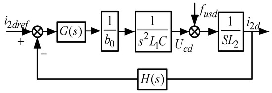
Figure 12.
System structure diagram of improved LADRC inverter.
In the formula, , , are the system DC bus current, bus current reference value, and total disturbance respectively; is the transfer function from the bus voltage reference input to the actual output; is the transfer function from the total disturbance to the actual output, that is, the anti-disturbance performance of the grid-connected inverter to maintain a stable bus voltage.
It can be seen from the amplitude frequency characteristic curve diagram in Figure 13 that the improved LADRC is obviously better than traditional LADRC. In the mid-frequency band, the bandwidth of the improved LADRC observer is larger than that of the traditional LADRC, Therefore, the improved LADRC tracking ability is more superior, and the anti-interference ability is strong. In the high frequency band, the two curves coincide.
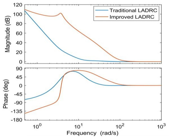
Figure 13.
Improved phase characteristic curve with conventional LADRC disturbance rejection.
5.4. Improved LADRC Stability Analysis
According to Formula (69), the closed-loop transfer function of the system is:
The above formula is simplified as:
In the above formula, and are respectively:
Because the controller bandwidth and the observer bandwidth is both positive, and the former coefficients in the closed-loop transfer function are all larger than zero, that is .
The stability of the wind power system can be judged by the Linard–Chippert algebraic stability criterion. If the Herviz determinant of even or odd order is positive, the system can be judged stable.
6. Simulation Research
Based on MATLAB and Simulink simulation software, this paper establishes a 1.5 million watt MW direct drive permanent magnet synchronous wind turbine model. The purpose is to verify the accuracy of the above mathematical model and the effectiveness of the controller and observer parameters. The control strategy of grid-connected inverter is a double closed loop structure of DC voltage outer loop and current inner loop based on grid voltage vector direction. Table A1 and Table A2 are some parameters related to permanent magnet synchronous generator (PMSG) and controller; the controller and observer parameters in the table are all obtained by engineering. Several different faults can be selected to simulate the inverter side and the grid side at different times. Several simulation failures are as follows:
- (I)
- the voltage at the grid connection point rises to 1138 V. Start t = 1.8 s, clear at t = 2.0 s;
- (II)
- the voltage at the grid connection point drops to 10042 V. Start at t = 1.8 s, and clear at t = 2.0 s;
- (III)
- the machine side load occurs at t = 1.8 s, the load decreases and the load fails;
- (IV)
- in the case of traditional and improved LADRC, the harmonic content of the system is compared.
6.1. MATLAB/Simulink Digital Simulation
6.1.1. Situation 1
The grid voltage symmetrical drop fault starts at t = 1.8 s and ends at t = 2.0 s, as shown in Figure 14 below. Figure 14 shows the situation where the voltage at the grid point drops to 1119 V and shows the DC bus Dynamic response to voltage.
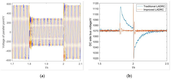
Figure 14.
Comparison of control effects in the case of symmetrical drop of grid voltage: (a) 50% grid voltage waveform of symmetrical drop of grid voltage; (b) symmetrical low drop of 50% bus voltage.
Table 1 shows the control performance index of the system, and regards the range of DC bus voltage fluctuation and adjustment time as the critical control performance index of the system. Combining Table 1 with Figure 14, you can clearly understand the DC bus voltage fluctuations and adjustment time; in the case of a 50% drop in the grid voltage, the improved LADRC adjustment time is much shorter than the traditional LADRC; voltage fluctuation range is basically the same; the above phenomenon shows that the improved LADRC has stronger anti-interference ability.

Table 1.
Performance index comparison of symmetrical voltage drop of the power grid.
6.1.2. Scenario 2
The grid voltage asymmetric drop fault occurs at t = 1.8 s and ends at t = 2.0 s. Figure 15 shows when the grid point voltage drops to 1010 V and shows the dynamic response of the DC bus voltage; when the grid voltage drops sharply, the DC bus voltage will rise rapidly and then stabilize.
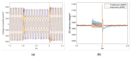
Figure 15.
Comparison of control effects under asymmetrical grid voltage drop conditions: (a) asymmetrical grid voltage drop circuit 50% grid voltage waveform, (b) asymmetrical low drop circuit 50% bus voltage.
Table 2 shows the control performance indicators of the system. The range of DC bus voltage fluctuations, adjustment time, and voltage stability are regarded as critical control performance indicators for the system. Combining 2 with Figure 15, you can clearly understand the fluctuation range and adjustment time of the DC bus voltage. When the grid voltage drops asymmetry by 50%, the improved LADRC adjustment time is shorter than the traditional LADRC, and the voltage fluctuation range is basically the same, both stabilized at 1070 V. The above phenomenon shows that the improved LADRC has a stronger anti-interference ability.
Table 2.
Comparison of performance indexes of power grid voltage asymmetry drop.
6.1.3. Scenario 3
As shown in Figure 16 below, a load on the grid side occurred at t = 1.8 s. Table 3 shows the control performance of the system. Combining Table 3 and Figure 16, it can be clearly understood that the bus voltage under the improved LADRC control has stronger anti-interference performance than the traditional LADRC, and the adjustment time is shortened by at least 0.3 s.
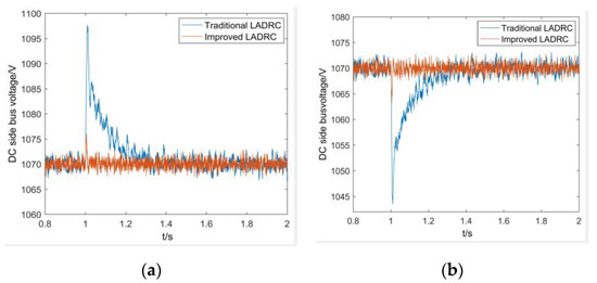
Figure 16.
Comparison of control effects under motor loading, unloading and load rejection conditions: (a) the motor is loaded with 50% Direct Current (DC) bus voltage, (b) motor load reduction 50% DC bus voltage.
Table 3.
A comparison of Performance Indexes of Grid Voltage Up and Down Load.
Table 3 shows the control performance indicators of the system. The DC bus voltage loading and unloading and the adjustment time is regarded as the most important control performance indicators of the system. Combining 3 with Figure 16, you can clearly understand the magnitude and adjustment time of DC bus voltage loading and unloading. When the grid voltage is increased or decreased by 50%, the improved LADRC adjustment time is shorter than the traditional LADRC. The LADRC DC bus voltage increase and decrease the load is smaller than the traditional LADRC, and finally stabilized at 1070 V; the above phenomenon shows that the improved LADRC has a stronger anti-interference ability.
6.1.4. Scenario 4
Figure 17 and Table 4 shows the harmonic content analysis of the improved and traditional LADRC. The simulation analysis of the above figure clearly shows that the harmonic content of the improved LADRC is lower than that of the traditional LADRC, so the improved LADRC is in terms of structural design. It is superior to traditional LADRC, and its ability to suppress harmonics is also stronger than traditional LADRC.
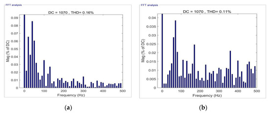
Figure 17.
Comparison of harmonic suppression effect between traditional LADRC and improved LADRC: (a) improve LADRC harmonic content, (b) traditional LADRC harmonic content.
Table 4.
Harmonic content comparison.
7. Results
This paper proposes an improved LADRC technology to improve the bus voltage stability, mainly to solve the influence of internal and external disturbances on the DC bus voltage. The mechanism to suppress internal and external disturbances is as follows: a first-order inertia link is added in the total disturbance channel to avoid introducing noise with the increase of observer bandwidth. Introducing the differential of the total disturbance into the traditional LESO, by observing the change trend of the total disturbance, an effective early correction signal is generated, which can effectively increase the bandwidth of the LESO and enhance its dynamic observation ability. The simulation analysis and comparison between the improved LADRC and the traditional LADRC under the working conditions of the symmetrical and asymmetrical drop of the power grid voltage, the loading and shedding of the motor, and the analysis of the harmonic content, the phenomenon shows that the improved LADRC has obvious advantages in controlling bus voltage stability.
Author Contributions
C.Y. conceived the main idea for the proposed improved LADRC and performed overall analysis; X.Z., Z.G., and Y.M. wrote this paper; C.W. and Y.Z. contributed to analyzing the experimental results. All authors have read and agreed to the published version of the manuscript.
Funding
This work was funded by the National Natural Science foundation of China (NO. 51877152) and Natural 533 Science Foundation of Tianjin of China (NO. 18JCZDJC97300).
Acknowledgments
The authors are grateful for the support from the National Natural Science foundation of 535 China (NO. 51877152), Natural Science Foundation of Tianjin of China (NO. 18JCZDJC97300), and Tianjin 536 University of Technology.
Conflicts of Interest
The authors declare no conflict of interest.
Abbreviations
| Acronym | Definition |
| SVPWM | Space Vector Pulse Width Modulation |
| LSEF | Linear State Error Feedback |
| LADRC | Linear Active Disturbance Rejection Control |
| DC | Direct Current |
| AC | Alternating Current |
| ESO | Extended State Observer |
| LESO | Linear Extended State Observer |
Appendix A
Table A1.
Parameters of Direct-Driven Permanent Magnet Wind Power Inverter.
Table A1.
Parameters of Direct-Driven Permanent Magnet Wind Power Inverter.
| System Parameter | Size |
|---|---|
| Rated power/KW | 10 |
| DC voltage/V | 22 |
| Filter Inductance mH | 0.74 |
| Filter Inductance mH | 0.055 |
| Filter Capacitor uF | 6.6 |
| Switching Period | 50 |
| Load Resistance/ | 15 |
Table A2.
Controller parameters.
Table A2.
Controller parameters.
| Controller Parameters | Size |
|---|---|
| Observer Bandwidth/ | 2950 |
| Controller Bandwidth/ | 800 |
| Time Constant/ | 0.004 |
| Correction Factor/ | 0.2 |
References
- Mian, W.; Guozhu, C. DC energy balance scheme for back-to-back PWM converters of wind power system. Electr. Power Autom. Equip. 2016, 36, 28–33. [Google Scholar]
- Zhang, Y.; Huang, S.; Luo, D. A novel half quasi-Z-source inverter for wind energy conversion systems. Proc. Csee 2017, 37, 5107–5117. [Google Scholar]
- Wu, W.; Liu, Y.; Chung, H.S.H.; Liserre, M.; Blaabjerg, F. Damping methods for resonances caused by LCL-filter-based current-controlled grid-tied power inverters: An overview. IEEE Trans. Ind. Electron. 2017, 64, 7402–7413. [Google Scholar] [CrossRef]
- Nambo, H.; Jinhwan, J.; Kwanghee, N. A fast dynamic Dc-link power-balancing Scheme for a PWM converter-inverter system. IEEE Trans. Ind. Electron. 2001, 48, 794–803. [Google Scholar]
- Liu, B.; Jin, H. Feed forward compensation control of dual PWM converter for permanent magnet direct driven wind turbine. Power Syst. Prot. Control. 2016, 42, 52–57. [Google Scholar]
- Zou, Z.; Cai, L.; Gan, H. Active disturbance rejection control strategy for voltage source PWM inverter. Acta Electrotech. 2004, 2, 84–88. [Google Scholar]
- Yang, L.; Zeng, J.; Ma, W.; Huang, Z. Voltage control of microgrid inverter based on improved second order linear active disturbance rejection technology. Power Syst. Autom. 2019, 43, 146–158. [Google Scholar]
- Zou, Z.; Cai, L.; Gan, H. The application of auto-disturbance rejection controller for voltage source PWM inverter. Trans. China Electrotech. Soc. 2004, 19, 84–88. [Google Scholar]
- Gao, Z. Scaling and bandwidth—Parameterization based controller tuning. In Proceedings of the American Control Conference, Minneapolis, MN, USA, 14–16 June 2006; pp. 4989–4996. [Google Scholar]
- Zhou, X.; Liu, M.; Ma, Y.; Yang, B.; Zhao, F.; Jing, Z. Improved second-order LADRC for wind power inverter bus voltage control. J. Power Syst. Autom. 2020, 32, 43–50. [Google Scholar]
- Saleem, M.; Ko, B.; Kim, S.; Kim, S.I.; Chowdhry, B.S.; Kim, R.Y. Active disturbance rejection control scheme for reducing mutual current and harmonics in multi-parallel grid-connected inverters. Energies 2019, 12, 4363. [Google Scholar] [CrossRef]
- Priyadarshi, N.; Ramachandaramurthy, V.; Padmanaban, S.; Azam, F. An ant colony optimized MPPT for standalone hybrid PV-wind power system with single Cuk converter. Energies 2019, 12, 167. [Google Scholar] [CrossRef]
- Yang, L.; Zeng, J.; Huang, Z. Application of linear active disturbance rejection technology in grid connected current control and active damping of LCL inverter. Power Grid Technol. 2019, 43, 1378–1386. [Google Scholar]
- Yuan, D.; Ma, X.; Zeng, Q. Research on frequency band characteristics and parameter configuration of linear active disturbance rejection controller for second-order systems. Control. Theory Appl. 2013, 30, 1630–1640. [Google Scholar]
- Zhou, X.; Liu, M.; Ma, Y.; Yang, B.; Zhao, F. Linear Active Disturbance Rejection Control for DC Bus Voltage of Permanent Magnet Synchronous Generator Based on Total Disturbance Differential. Energies 2019, 12, 3906. [Google Scholar] [CrossRef]
- Wang, J.; Liao, R.; Shi, C.; Wang, S. Linear extended state observer-based motion synchronization control for hybrid actuation system of more electric aircraft. Sensors 2017, 11, 2444. [Google Scholar] [CrossRef]
- Zhou, X.; Tian, C.; Ma, Y.; Liu, S.; Zhao, J.; Liu, J. SHAPF model based on LADRC and its current tracking control. Electr. Power Autom. Equip. 2013, 33, 49–54. [Google Scholar]
- Liu, L.; Xu, Z.; Mei, Q. Induction motor drive system based on the flux observer LESO and LADRC. Congr. Intell. Syst. IEEE 2009, 2, 248–252. [Google Scholar]
- Zhou, X.; Liu, W.; Ma, Y.; Zhao, J.; Wang, D.; Qiu, Y. Analysis of three-phase four wire parallel active power filter system based on LADRC. High Volt. Technol. 2016, 42, 1290–1299. [Google Scholar]
- Huang, Y.; Xue, W. Active disturbance rejection control: Methodology and theoretical analysis. ISA Trans. 2014, 53, 963–976. [Google Scholar] [CrossRef]
- Han, J. From PID to Active Disturbance Rejection Control. IEEE Trans. Ind. Electron. 2009, 56, 900–906. [Google Scholar] [CrossRef]
- Zhu, S.; Wang, Y.; He, C.; Ling, Y.; Tao, l.; Zhou, X. Wind power grid connected control and stability analysis of first order LADRC. J. Power Syst. Autom. 2020, 32, 33–38. [Google Scholar]
- Ma, Y.; Yang, L.; Zhou, X.; Yang, X.; Zhou, Y.; Zhang, B. Linear Active Disturbance Rejection Control for DC Bus Voltage Under Low-Voltage Ride-Through at the Grid-Side of Energy Storage System. Energies 2020, 13, 1207. [Google Scholar] [CrossRef]


© 2020 by the authors. Licensee MDPI, Basel, Switzerland. This article is an open access article distributed under the terms and conditions of the Creative Commons Attribution (CC BY) license (http://creativecommons.org/licenses/by/4.0/).