Figure 1.
Lightning current impulse.
Figure 1.
Lightning current impulse.
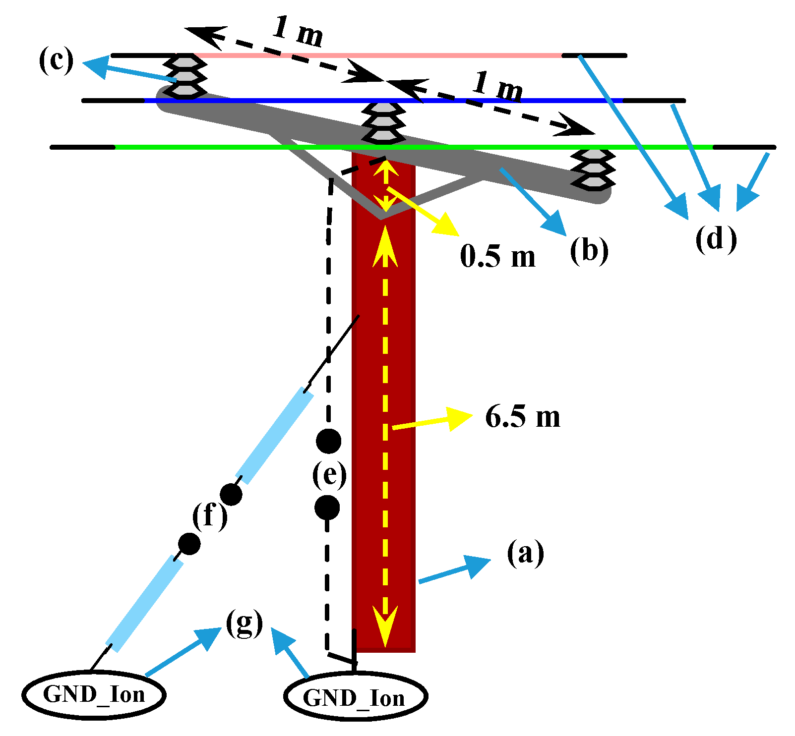
Figure 2.
Dimensions and different parts of the medium voltage wood pole for a 3-phase distribution network: (a) pole, (b) cross arm, (c) insulator, (d) overhead lines, (e) lead wire (used for grounding), (f) guy wire, and (g) earthing system.
Figure 2.
Dimensions and different parts of the medium voltage wood pole for a 3-phase distribution network: (a) pole, (b) cross arm, (c) insulator, (d) overhead lines, (e) lead wire (used for grounding), (f) guy wire, and (g) earthing system.
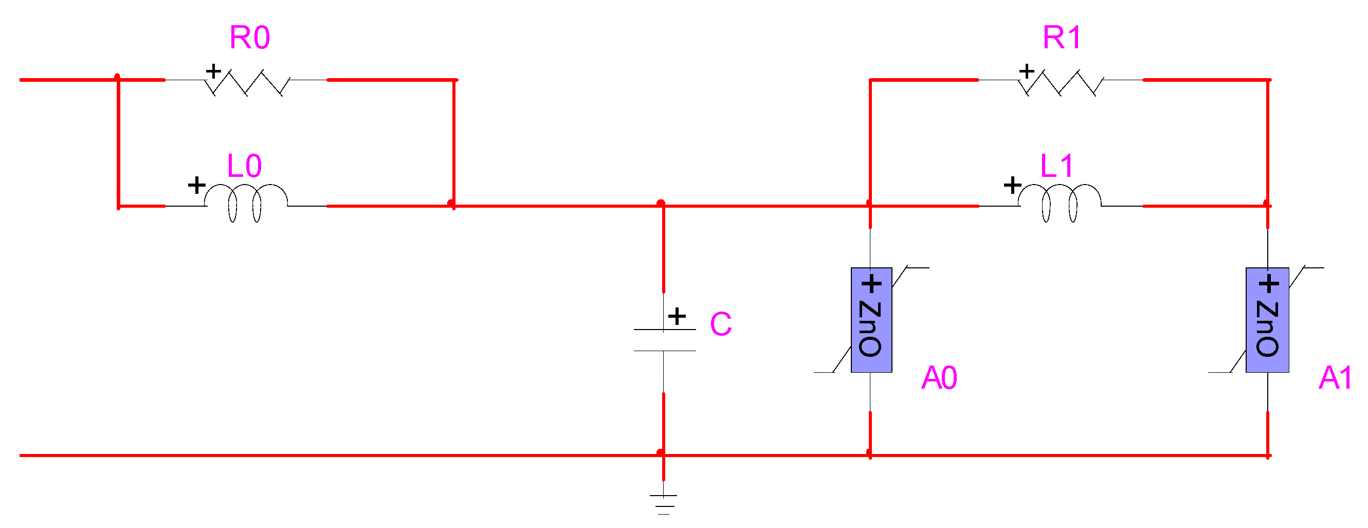
Figure 3.
Frequency-dependent metal oxide surge arrester [
42].
Figure 3.
Frequency-dependent metal oxide surge arrester [
42].
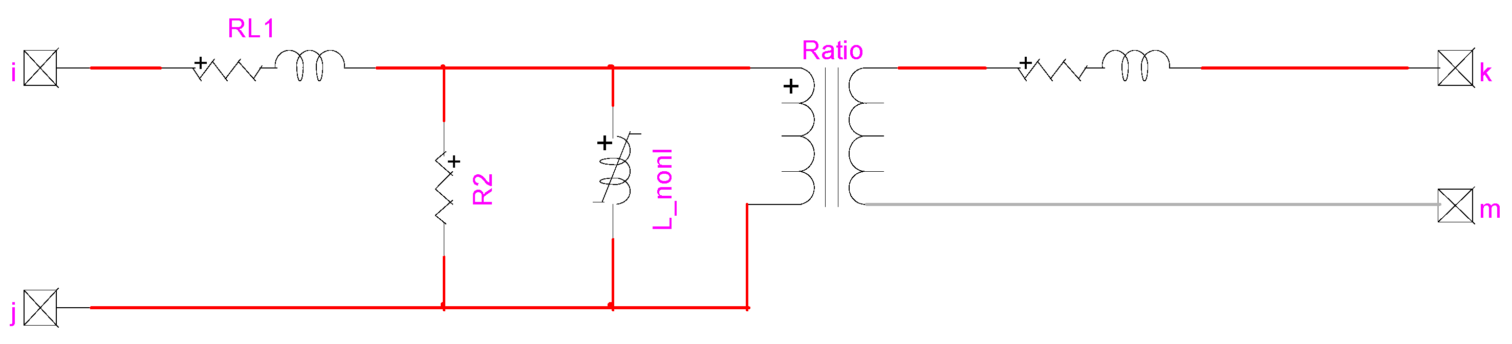
Figure 4.
Basic building block for each phase of the transformer, EMTP-RV model.
Figure 4.
Basic building block for each phase of the transformer, EMTP-RV model.
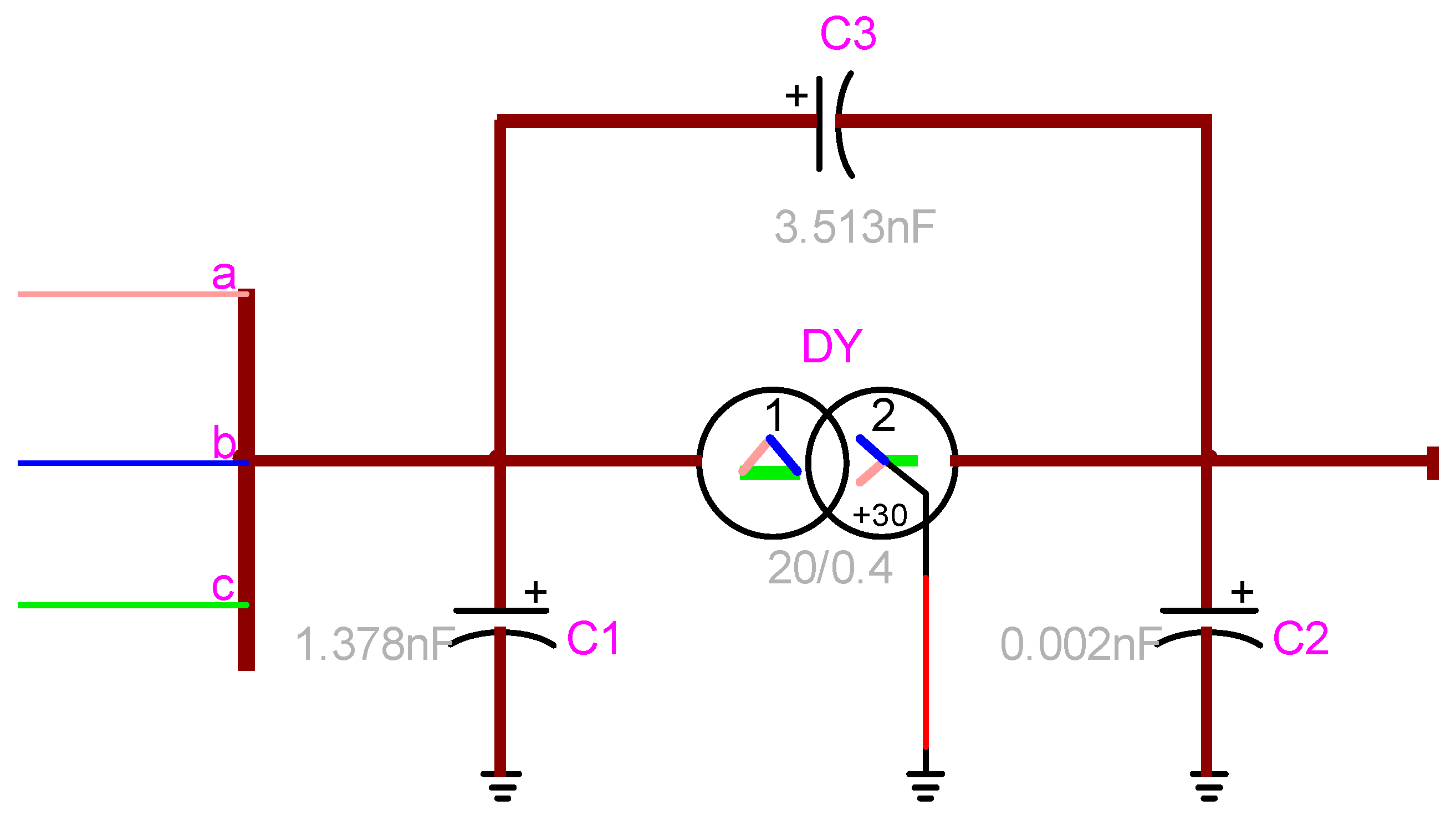
Figure 5.
connection model of the transformer with measured capacitances.
Figure 5.
connection model of the transformer with measured capacitances.
Figure 6.
Sample medium voltage network.
Figure 6.
Sample medium voltage network.
Figure 7.
Adjustable sphere-sphere spark gap [
45].
Figure 7.
Adjustable sphere-sphere spark gap [
45].
Figure 8.
(
a) Applied nonstandard 125 kV lightning impulse; (
b) Measured overvoltage stress in the presence of spark gap [
45].
Figure 8.
(
a) Applied nonstandard 125 kV lightning impulse; (
b) Measured overvoltage stress in the presence of spark gap [
45].
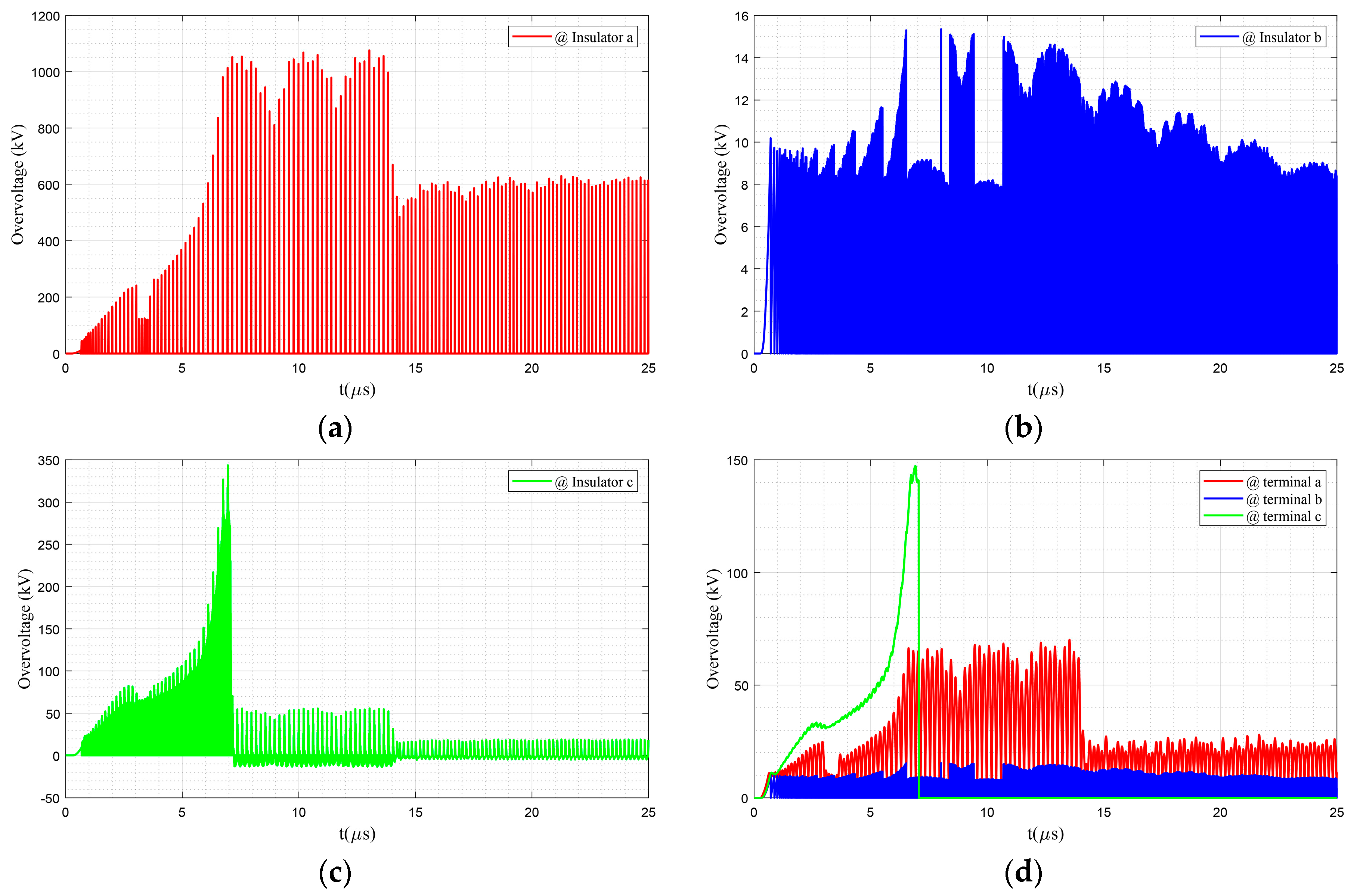
Figure 9.
Flashover occurrence across (a) insulator a, (b) insulator b, and (c) insulator c, and (d) performance of the spark gap of the same pole against lightning impulses.
Figure 9.
Flashover occurrence across (a) insulator a, (b) insulator b, and (c) insulator c, and (d) performance of the spark gap of the same pole against lightning impulses.
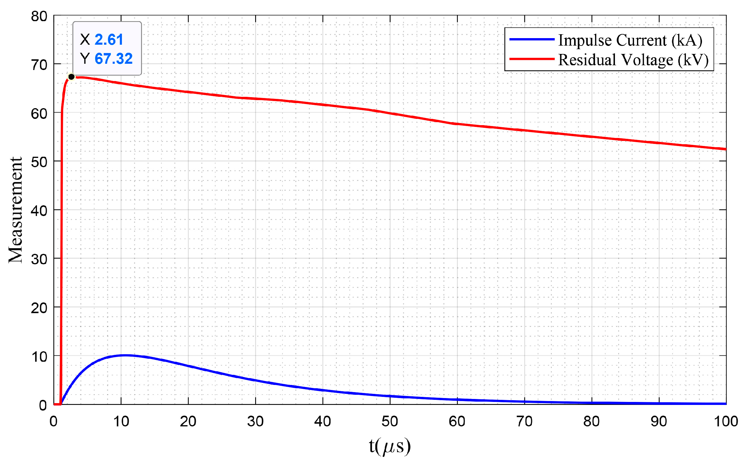
Figure 10.
Residual voltage under a 10 kA current impulse (8/20 μs).
Figure 10.
Residual voltage under a 10 kA current impulse (8/20 μs).
Figure 11.
Performance of surge arrester when direct lightning is applied on (a) the intermediate pole adjacent to the transformer and (b) the transformer pole.
Figure 11.
Performance of surge arrester when direct lightning is applied on (a) the intermediate pole adjacent to the transformer and (b) the transformer pole.
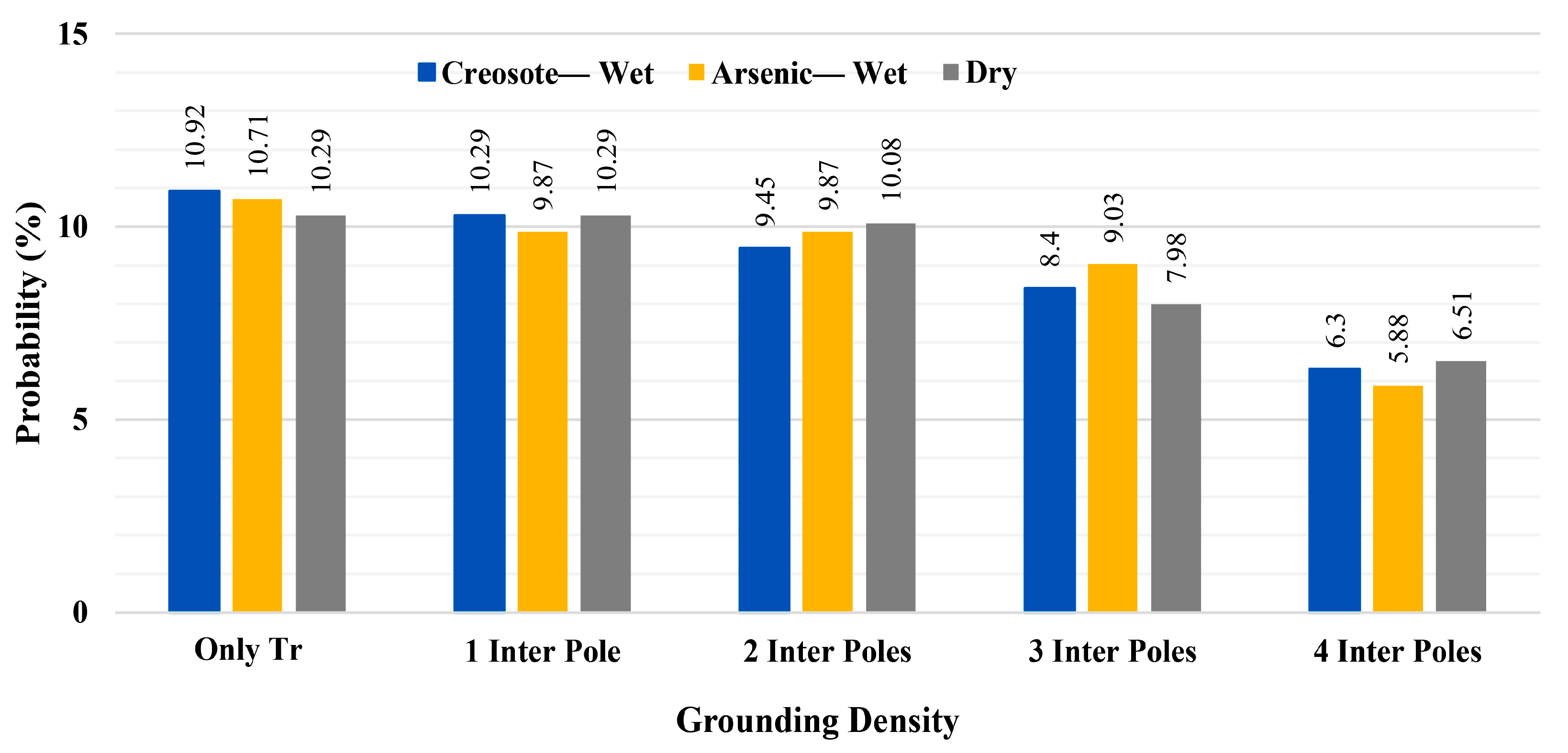
Figure 12.
Comparison among the probabilities of transformer overvoltage stress, Case 1 (only transformer poles grounded).
Figure 12.
Comparison among the probabilities of transformer overvoltage stress, Case 1 (only transformer poles grounded).
Figure 13.
Overvoltage stress at three terminals of transformer mounted at pole #36; Network with dry poles under a lightning strike on pole #35, Case 1.
Figure 13.
Overvoltage stress at three terminals of transformer mounted at pole #36; Network with dry poles under a lightning strike on pole #35, Case 1.
Figure 14.
Comparison among the probabilities of transformer overvoltage tension under three network configurations. Case 2, grounding one intermediate pole between two transformer poles.
Figure 14.
Comparison among the probabilities of transformer overvoltage tension under three network configurations. Case 2, grounding one intermediate pole between two transformer poles.
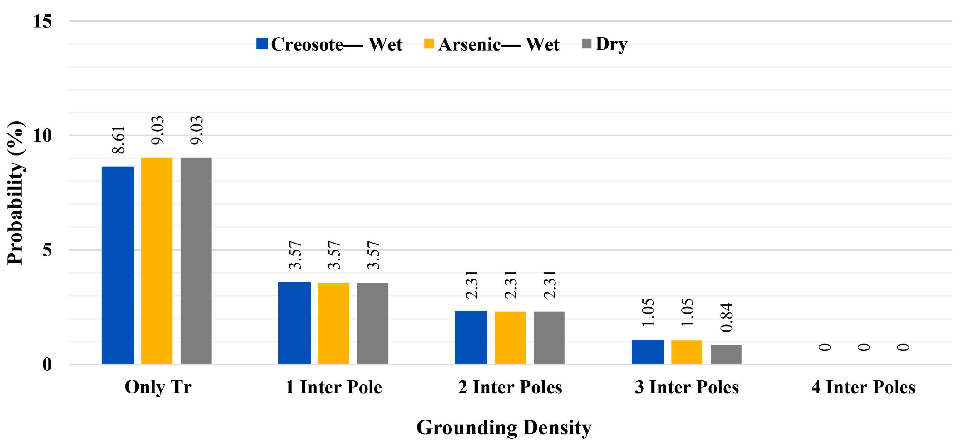
Figure 15.
Comparison among the probabilities of transformers experiencing overvoltage stress above 150 kV under different grounding densities, Case 2.
Figure 15.
Comparison among the probabilities of transformers experiencing overvoltage stress above 150 kV under different grounding densities, Case 2.
Figure 16.
Comparison among the probabilities of transformers experiencing overvoltage stress above 125 kV under different grounding densities, Case 2.
Figure 16.
Comparison among the probabilities of transformers experiencing overvoltage stress above 125 kV under different grounding densities, Case 2.
Figure 17.
Comparison among the probabilities of transformers overvoltage stress above 85 kV under different grounding conditions, Case 2.
Figure 17.
Comparison among the probabilities of transformers overvoltage stress above 85 kV under different grounding conditions, Case 2.
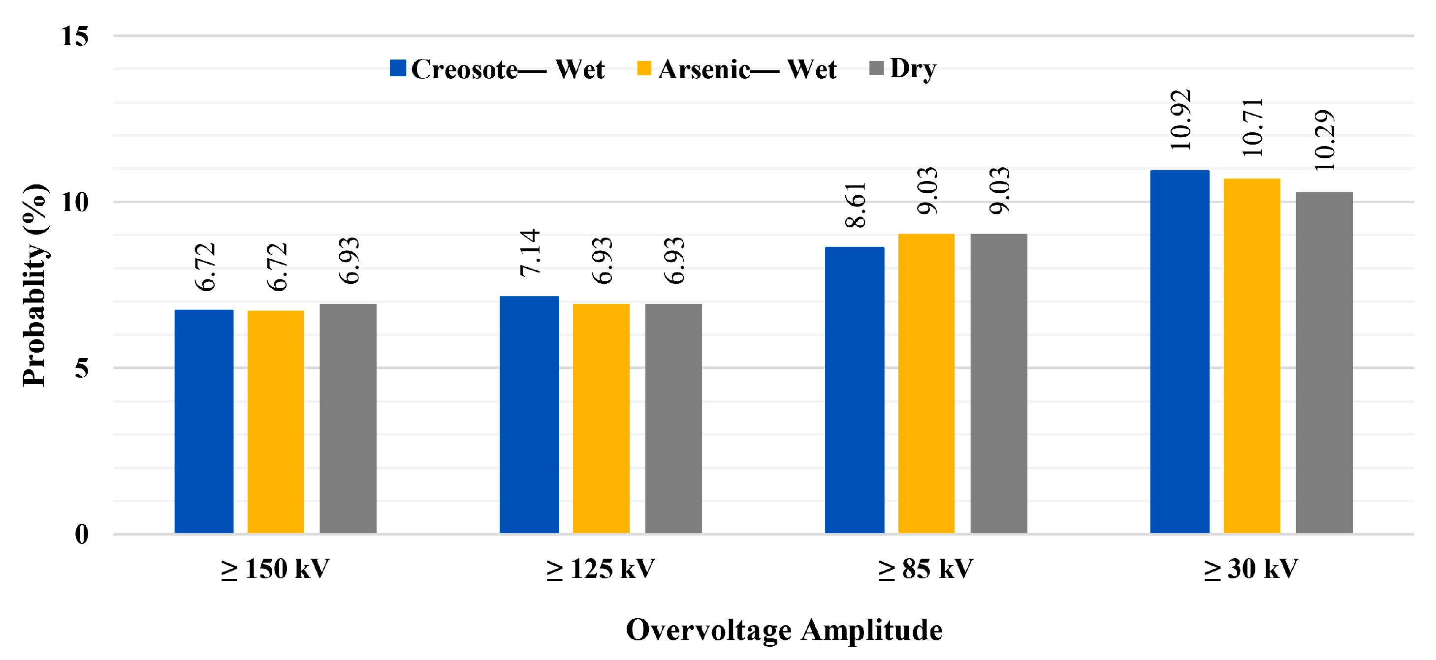
Figure 18.
Comparison among the probabilities of transformer overvoltage stress above 30 kV under different grounding conditions, Case 2.
Figure 18.
Comparison among the probabilities of transformer overvoltage stress above 30 kV under different grounding conditions, Case 2.
Figure 19.
Comparison among the overvoltage stress at terminal c of the transformer mounted at pole #36, network with dry poles under a lightning strike on pole #35, Case 2.
Figure 19.
Comparison among the overvoltage stress at terminal c of the transformer mounted at pole #36, network with dry poles under a lightning strike on pole #35, Case 2.
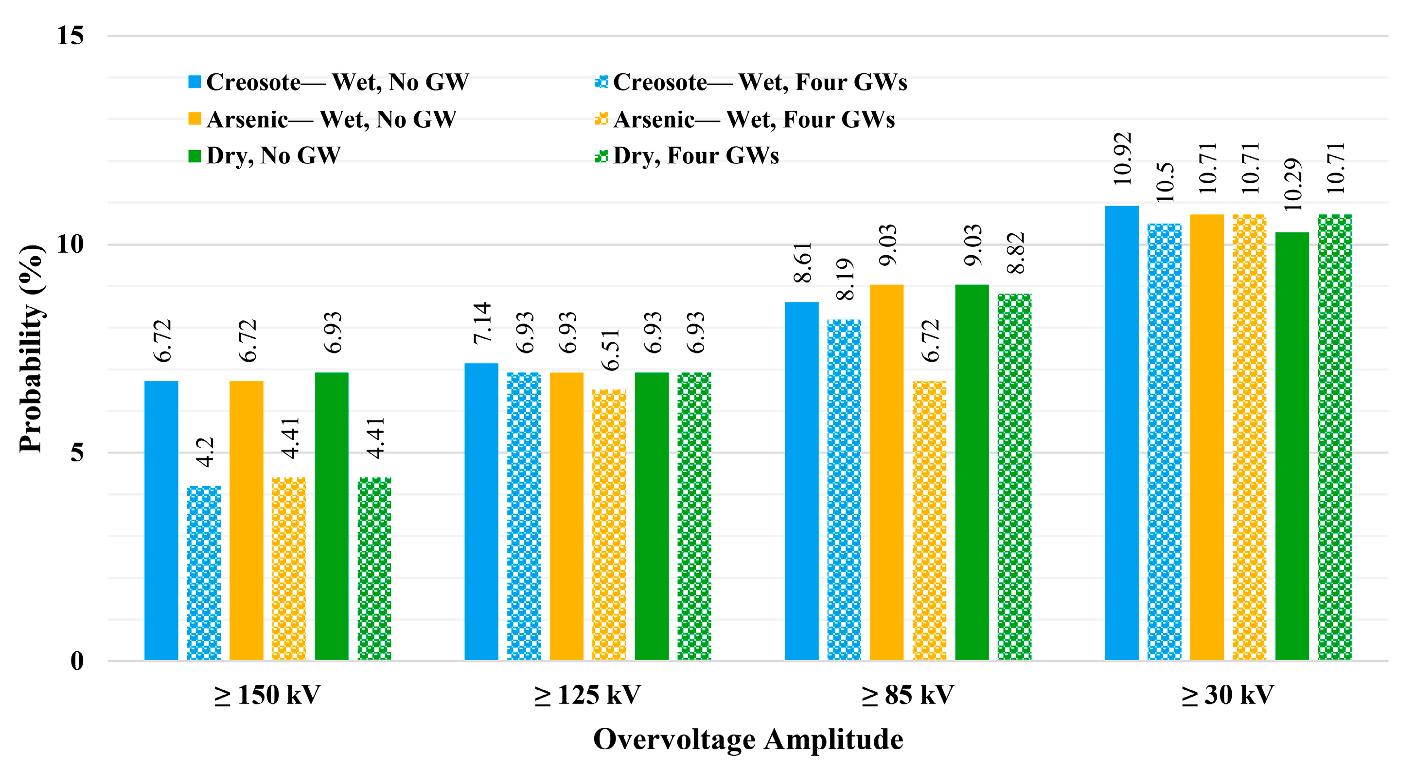
Figure 20.
Comparison among the probabilities of transformers experiencing four overvoltage stress levels for three configurations of the network with no guy wire (No GW) and four guy wires (Four GWs).
Figure 20.
Comparison among the probabilities of transformers experiencing four overvoltage stress levels for three configurations of the network with no guy wire (No GW) and four guy wires (Four GWs).
Figure 21.
Flashover discharge currents of four intermediate poles supported by guy wires: (a) Intermediate Pole #32, (b) Intermediate Pole #33, (c) Intermediate Pole #34, and (d) Intermediate Pole #35; Network with dry poles and direct lightning applied on pole #34.
Figure 21.
Flashover discharge currents of four intermediate poles supported by guy wires: (a) Intermediate Pole #32, (b) Intermediate Pole #33, (c) Intermediate Pole #34, and (d) Intermediate Pole #35; Network with dry poles and direct lightning applied on pole #34.
Figure 22.
Overvoltage at terminal c of the transformer mounted on (a) pole #31, and (b) pole #36; Network with dry poles and direct lightning applied on pole #34.
Figure 22.
Overvoltage at terminal c of the transformer mounted on (a) pole #31, and (b) pole #36; Network with dry poles and direct lightning applied on pole #34.
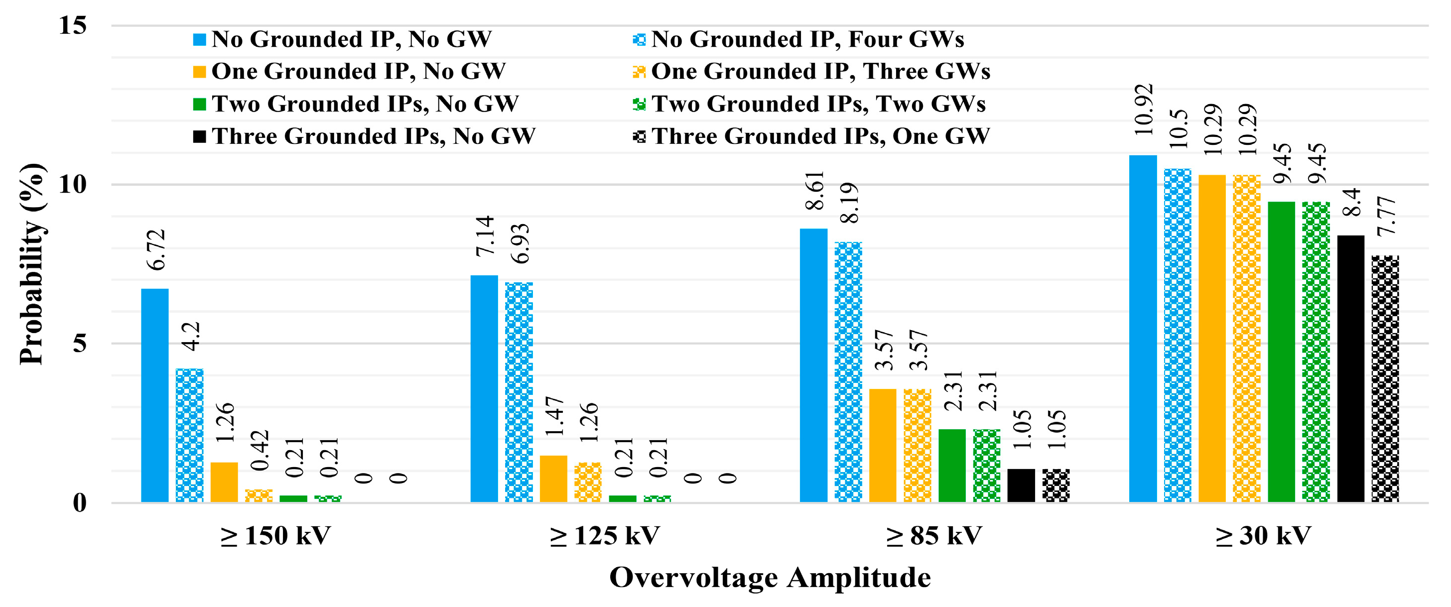
Figure 23.
Comparison among the probabilities of transformers experiencing four overvoltage stress levels under different combinations of grounding and guy wire (GW) configurations of intermediate poles (IP); Network with wet creosote-impregnated poles.
Figure 23.
Comparison among the probabilities of transformers experiencing four overvoltage stress levels under different combinations of grounding and guy wire (GW) configurations of intermediate poles (IP); Network with wet creosote-impregnated poles.
Figure 24.
Comparison among the probabilities of transformers experiencing four overvoltage stress levels under different combinations of grounding and guy wire (GW) configurations of intermediate poles (IP); Network with wet arsenic-impregnated poles.
Figure 24.
Comparison among the probabilities of transformers experiencing four overvoltage stress levels under different combinations of grounding and guy wire (GW) configurations of intermediate poles (IP); Network with wet arsenic-impregnated poles.
Figure 25.
Comparison among the probabilities of transformers experiencing four overvoltage stress levels under different combinations of grounding and guy wire (GW) configurations of intermediate poles (IP); Network with dry poles.
Figure 25.
Comparison among the probabilities of transformers experiencing four overvoltage stress levels under different combinations of grounding and guy wire (GW) configurations of intermediate poles (IP); Network with dry poles.
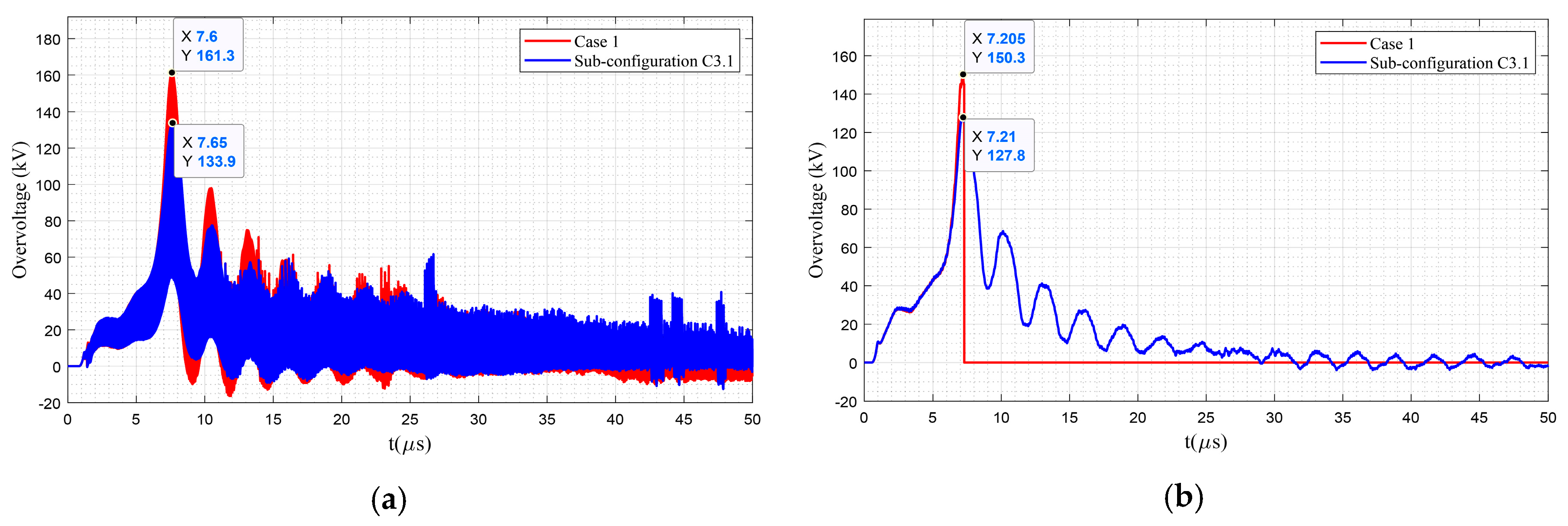
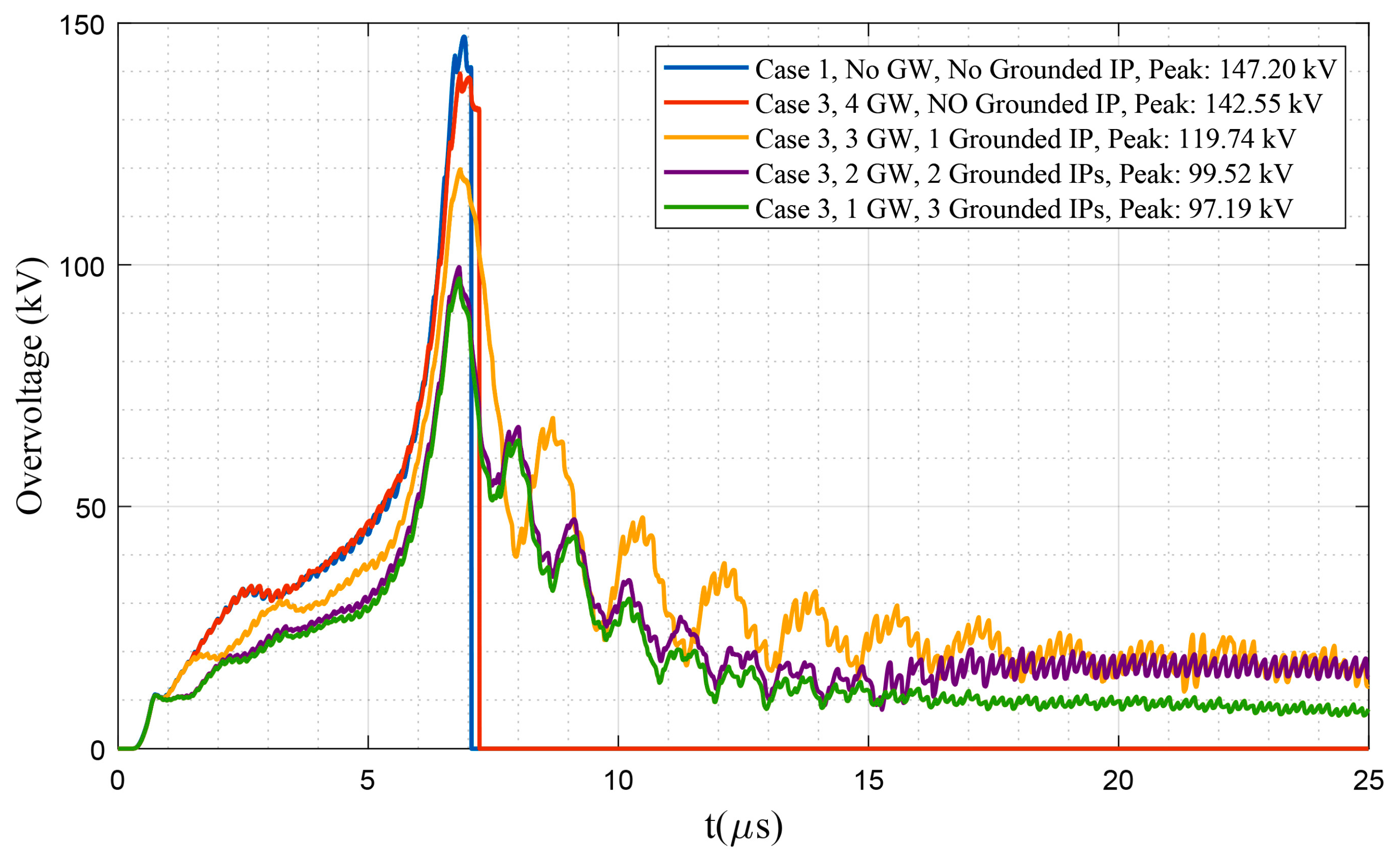
Figure 26.
Comparison among the overvoltage stress at terminal c of the transformer mounted at pole #36 under different combinations of grounding and guy wire (GW) configurations of intermediate poles (IP); Network with dry poles under a lightning strike on pole #35.
Figure 26.
Comparison among the overvoltage stress at terminal c of the transformer mounted at pole #36 under different combinations of grounding and guy wire (GW) configurations of intermediate poles (IP); Network with dry poles under a lightning strike on pole #35.
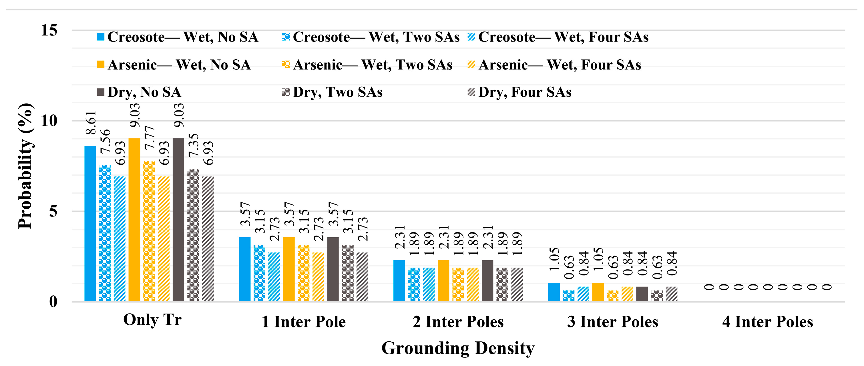
Figure 27.
Comparison among the probabilities of transformers experiencing overvoltage stress above 150 kV under different grounding densities of intermediate poles (Inter Pole) and considering two and four surge arresters (SAs); Network with dry poles.
Figure 27.
Comparison among the probabilities of transformers experiencing overvoltage stress above 150 kV under different grounding densities of intermediate poles (Inter Pole) and considering two and four surge arresters (SAs); Network with dry poles.
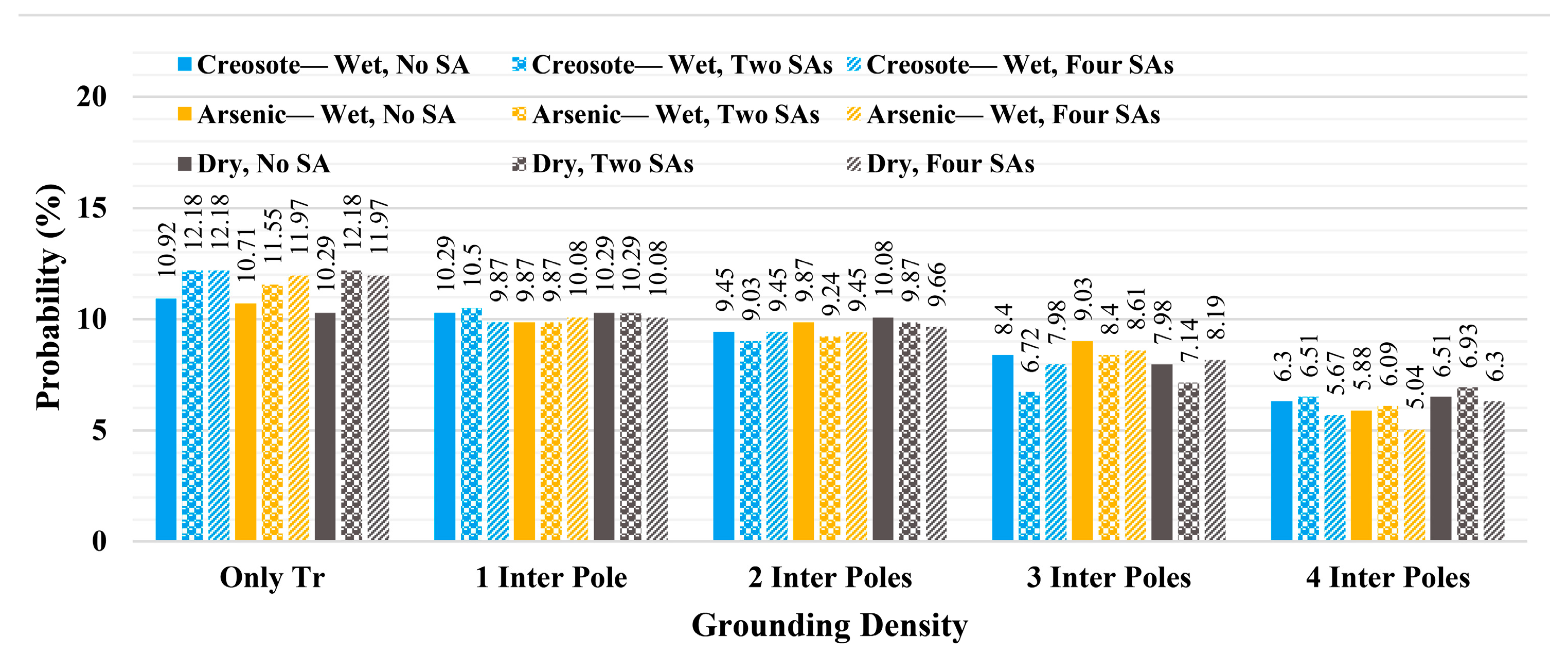
Figure 28.
Comparison among the probabilities of transformers experiencing overvoltage stress above 125 kV under different grounding densities of intermediate poles (Inter Pole) and considering two and four surge arresters (SAs); Network with dry poles.
Figure 28.
Comparison among the probabilities of transformers experiencing overvoltage stress above 125 kV under different grounding densities of intermediate poles (Inter Pole) and considering two and four surge arresters (SAs); Network with dry poles.
Figure 29.
Comparison among the probabilities of transformers experiencing overvoltage stress above 85 kV under different grounding densities of intermediate poles (Inter Pole) and considering two and four surge arresters (SAs); Network with dry poles.
Figure 29.
Comparison among the probabilities of transformers experiencing overvoltage stress above 85 kV under different grounding densities of intermediate poles (Inter Pole) and considering two and four surge arresters (SAs); Network with dry poles.
Figure 30.
Comparison among the probabilities of transformers experiencing overvoltage stress above 30 kV under different grounding densities of intermediate poles (Inter Pole) and considering two and four surge arresters (SAs); Network with dry poles.
Figure 30.
Comparison among the probabilities of transformers experiencing overvoltage stress above 30 kV under different grounding densities of intermediate poles (Inter Pole) and considering two and four surge arresters (SAs); Network with dry poles.
Figure 31.
Comparison among the overvoltage stress at terminal c of the transformer mounted at pole #36 under different grounding densities; Network with dry poles considering two surge arrester protected transformers and under a lightning strike on pole #35.
Figure 31.
Comparison among the overvoltage stress at terminal c of the transformer mounted at pole #36 under different grounding densities; Network with dry poles considering two surge arrester protected transformers and under a lightning strike on pole #35.
Figure 32.
Comparison among the overvoltage stress at terminal c of the transformer mounted at pole #36 under different combinations of grounding and guy wire (GW) configurations of intermediate poles (IP); Network with dry poles considering four surge-arrester-protected transformers under a lightning strike on pole #35.
Table 1.
Parameters of direct lightning [
13].
Table 1.
Parameters of direct lightning [
13].
| Parameter | Symbol | Value |
|---|
| Maximum current () | | 27.7 |
| Front time () | | 3.83 |
| Maximum steepness | | 23.3 |
| Time to half value () | | 77.5 |
Table 2.
Number of transformers with at least one phase reaching the critical overvoltage level. Case 1, wet creosote-impregnated poles and grounded transformer poles.
Table 2.
Number of transformers with at least one phase reaching the critical overvoltage level. Case 1, wet creosote-impregnated poles and grounded transformer poles.
| Applied at Pole | #1 | #4 | #7 | #10 | #13 | #16 | #19 | #22 | #25 | #28 | #31 | #34 | #37 | #40 |
| | 2 | 1 | 1 | 2 | | 2 | 1 | 1 | 2 | | 2 | | 1 |
| | 2 | 1 | 1 | 2 | | 2 | 1 | 1 | 3 | | 2 | 1 | 1 |
| | 2 | 1 | 1 | 2 | | 2 | 2 | 2 | 3 | | 2 | 2 | 1 |
| 1 | 2 | 3 | 2 | 2 | 1 | 2 | 2 | 2 | 3 | 1 | 2 | 2 | 2 |
| Applied at Pole | #43 | #46 | #49 | #52 | #55 | #58 | #61 | #64 | #67 | #70 | #73 | #76 | #79 | #82 |
| 2 | | 2 | 1 | 1 | 2 | | 2 | 1 | 1 | 2 | | 2 | 1 |
| 2 | | 2 | 1 | 1 | 2 | | 2 | 1 | 1 | 2 | | 2 | 1 |
| 2 | | 2 | 2 | 2 | 2 | | 2 | 2 | 2 | 2 | | 2 | 1 |
| 2 | 1 | 2 | 2 | 2 | 2 | 1 | 2 | 2 | 2 | 2 | 1 | 2 | 2 |
Table 3.
Number of transformers with at least one phase reaching the critical overvoltage level. Case 1, wet arsenic-impregnated poles and grounded transformer poles.
Table 3.
Number of transformers with at least one phase reaching the critical overvoltage level. Case 1, wet arsenic-impregnated poles and grounded transformer poles.
| Applied at Pole | #1 | #4 | #7 | #10 | #13 | #16 | #19 | #22 | #25 | #28 | #31 | #34 | #37 | #40 |
| | 2 | 1 | 1 | 2 | | 2 | 1 | 1 | 2 | | 2 | | 1 |
| | 2 | 1 | 1 | 2 | | 2 | 1 | 1 | 2 | | 2 | 1 | 1 |
| | 2 | 2 | 2 | 2 | | 2 | 2 | 2 | 2 | | 2 | 2 | 2 |
| 1 | 2 | 3 | 2 | 2 | 1 | 2 | 2 | 2 | 2 | 1 | 2 | 2 | 2 |
| Applied at Pole | #43 | #46 | #49 | #52 | #55 | #58 | #61 | #64 | #67 | #70 | #73 | #76 | #79 | #82 |
| 2 | | 2 | 1 | 1 | 2 | | 2 | 1 | 1 | 2 | | 2 | 1 |
| 2 | | 2 | 1 | 1 | 2 | | 2 | 1 | 1 | 2 | | 2 | 1 |
| 2 | | 2 | 2 | 2 | 2 | | 2 | 2 | 2 | 2 | | 2 | 1 |
| 2 | 1 | 2 | 2 | 2 | 2 | 1 | 2 | 2 | 2 | 2 | 1 | 2 | 2 |
Table 4.
Number of transformers with at least one phase reaching the critical overvoltage level. Case 1, dry poles and grounded transformer poles.
Table 4.
Number of transformers with at least one phase reaching the critical overvoltage level. Case 1, dry poles and grounded transformer poles.
| Applied at Pole | #1 | #4 | #7 | #10 | #13 | #16 | #19 | #22 | #25 | #28 | #31 | #34 | #37 | #40 |
| | 2 | 1 | 1 | 2 | | 2 | 1 | 1 | 2 | | 2 | 1 | 1 |
| | 2 | 1 | 1 | 2 | | 2 | 1 | 1 | 2 | | 2 | 1 | 1 |
| | 2 | 2 | 2 | 2 | | 2 | 2 | 2 | 2 | | 2 | 2 | 2 |
| 1 | 2 | 2 | 2 | 2 | 1 | 2 | 2 | 2 | 2 | 1 | 2 | 2 | 2 |
| Applied at Pole | #43 | #46 | #49 | #52 | #55 | #58 | #61 | #64 | #67 | #70 | #73 | #76 | #79 | #82 |
| 2 | | 2 | 1 | 1 | 2 | | 2 | 1 | 1 | 2 | | 2 | 1 |
| 2 | | 2 | 1 | 1 | 2 | | 2 | 1 | 1 | 2 | | 2 | 1 |
| 2 | | 2 | 2 | 2 | 2 | | 2 | 2 | 2 | 2 | | 2 | 1 |
| 2 | 1 | 2 | 2 | 2 | 2 | 1 | 2 | 2 | 2 | 2 | 1 | 2 | 1 |
Table 5.
Number of transformers with at least one phase reaching the critical overvoltage level. Case 2, wet creosote-impregnated poles and grounding one intermediate pole between two transformer poles.
Table 5.
Number of transformers with at least one phase reaching the critical overvoltage level. Case 2, wet creosote-impregnated poles and grounding one intermediate pole between two transformer poles.
| Applied at Pole | #1 | #4 | #7 | #10 | #13 | #16 | #19 | #22 | #25 | #28 | #31 | #34 | #37 | #40 |
| | | | 1 | | | | | 1 | | | | | 1 |
| | | | 1 | | | | | 1 | | | | | 1 |
| | 1 | 1 | 1 | | | 1 | 1 | 1 | | | 1 | 1 | 1 |
| 1 | 2 | 2 | 2 | 2 | 1 | 2 | 2 | 2 | 2 | 1 | 2 | 2 | 2 |
| Applied at Pole | #43 | #46 | #49 | #52 | #55 | #58 | #61 | #64 | #67 | #70 | #73 | #76 | #79 | #82 |
| | | | | 1 | | | | | 1 | | | | 1 |
| | | | | 1 | | | | | 1 | | | 1 | 1 |
| | | 1 | 1 | 1 | | | 1 | 1 | 1 | | | 1 | 1 |
| 2 | 1 | 2 | 2 | 2 | 2 | 1 | 2 | 2 | 2 | 2 | 1 | 2 | 1 |
Table 6.
Number of transformers with at least one phase reaching the critical overvoltage level. Case 2, wet arsenic-impregnated poles and grounding one intermediate pole between two transformer poles.
Table 6.
Number of transformers with at least one phase reaching the critical overvoltage level. Case 2, wet arsenic-impregnated poles and grounding one intermediate pole between two transformer poles.
| Applied at Pole | #1 | #4 | #7 | #10 | #13 | #16 | #19 | #22 | #25 | #28 | #31 | #34 | #37 | #40 |
| | | | 1 | | | | | 1 | | | | | 1 |
| | | | 1 | | | | | 1 | | | | | 1 |
| | 1 | 1 | 1 | | | 1 | 1 | 1 | | | 1 | 1 | 1 |
| 1 | 2 | 2 | 2 | 2 | 1 | 2 | 2 | 2 | 2 | 1 | 2 | 2 | 1 |
| Applied at Pole | #43 | #46 | #49 | #52 | #55 | #58 | #61 | #64 | #67 | #70 | #73 | #76 | #79 | #82 |
| | | | | 1 | | | | | 1 | | | | 1 |
| | | | | 1 | | | | | 1 | | | 1 | 1 |
| | | 1 | 1 | 1 | | | 1 | 1 | 1 | | | 1 | 1 |
| 2 | 1 | 2 | 2 | 1 | 2 | 1 | 2 | 2 | 2 | 2 | 1 | 2 | 1 |
Table 7.
Number of transformers with at least one phase reaching the critical overvoltage level. Case 2, dry poles and grounding one intermediate pole between two transformer poles.
Table 7.
Number of transformers with at least one phase reaching the critical overvoltage level. Case 2, dry poles and grounding one intermediate pole between two transformer poles.
| Applied at Pole | #1 | #4 | #7 | #10 | #13 | #16 | #19 | #22 | #25 | #28 | #31 | #34 | #37 | #40 |
| | | | 1 | | | | | 1 | | | | | 1 |
| | | | 1 | | | | | 1 | | | | | 1 |
| | 1 | 1 | 1 | | | 1 | 1 | 1 | | | 1 | 1 | 1 |
| 1 | 2 | 2 | 2 | 2 | 1 | 2 | 2 | 2 | 2 | 1 | 2 | 2 | 2 |
| Applied at Pole | #43 | #46 | #49 | #52 | #55 | #58 | #61 | #64 | #67 | #70 | #73 | #76 | #79 | #82 |
| | | | | 1 | | | | | 1 | | | | 1 |
| | | | | 1 | | | | | 1 | | | 1 | 1 |
| | | 1 | 1 | 1 | | | 1 | 1 | 1 | | | 1 | 1 |
| 2 | 1 | 2 | 2 | 2 | 2 | 1 | 2 | 2 | 2 | 2 | 1 | 2 | 1 |
Table 8.
Number of transformers with at least one phase reaching the critical overvoltage level. Case 3, wet creosote-impregnated poles, sub-configuration C3.1.
Table 8.
Number of transformers with at least one phase reaching the critical overvoltage level. Case 3, wet creosote-impregnated poles, sub-configuration C3.1.
| Applied at Pole | #1 | #4 | #7 | #10 | #13 | #16 | #19 | #22 | #25 | #28 | #31 | #34 | #37 | #40 |
| | 2 | 1 | 1 | 1 | | 1 | 1 | 1 | 1 | | | | 1 |
| | 2 | 1 | 1 | 2 | | 2 | 1 | 1 | 2 | | 2 | 1 | 1 |
| | 2 | 2 | 2 | 2 | | 2 | 2 | 2 | 2 | | 2 | 2 | 1 |
| 1 | 2 | 2 | 2 | 2 | 1 | 2 | 2 | 2 | 2 | 1 | 2 | 2 | 2 |
| Applied at Pole | #43 | #46 | #49 | #52 | #55 | #58 | #61 | #64 | #67 | #70 | #73 | #76 | #79 | #82 |
| | | 1 | 1 | 1 | 1 | | 1 | 1 | 1 | 1 | | 1 | 1 |
| 2 | | 2 | 1 | 1 | 2 | | 2 | 1 | 1 | 2 | | 2 | 1 |
| 2 | | 2 | 1 | 1 | 2 | | 2 | 1 | 2 | 2 | | 2 | 1 |
| 2 | 1 | 2 | 2 | 2 | 2 | 1 | 2 | 2 | 2 | 2 | 1 | 2 | 2 |
Table 9.
Number of transformers with at least one phase reaching the critical overvoltage level. Case 3, wet arsenic-impregnated poles, sub-configuration C3.1.
Table 9.
Number of transformers with at least one phase reaching the critical overvoltage level. Case 3, wet arsenic-impregnated poles, sub-configuration C3.1.
| Applied at Pole | #1 | #4 | #7 | #10 | #13 | #16 | #19 | #22 | #25 | #28 | #31 | #34 | #37 | #40 |
| | 1 | 1 | 1 | 1 | | 1 | 1 | 1 | 1 | | | 1 | 1 |
| | 1 | 1 | 1 | 2 | | 2 | 1 | 1 | 2 | | 2 | 1 | 1 |
| | 1 | 1 | 1 | 2 | | 2 | 1 | 2 | 2 | | 2 | 1 | 1 |
| 1 | 3 | 2 | 2 | 2 | 1 | 2 | 2 | 2 | 2 | 1 | 2 | 2 | 2 |
| Applied at Pole | #43 | #46 | #49 | #52 | #55 | #58 | #61 | #64 | #67 | #70 | #73 | #76 | #79 | #82 |
| 1 | | 1 | 1 | 1 | 1 | | 1 | 1 | 1 | 1 | | 1 | 1 |
| 2 | | 1 | 1 | 1 | 2 | | 2 | 1 | 1 | 2 | | 2 | 1 |
| 2 | | 1 | 1 | 1 | 2 | | 2 | 1 | 1 | 2 | | 2 | 1 |
| 2 | 1 | 2 | 2 | 2 | 2 | 1 | 2 | 2 | 2 | 2 | 1 | 2 | 2 |
Table 10.
Number of transformers with at least one phase reaching the critical overvoltage level. Case 3, dry poles, sub-configuration C3.1.
Table 10.
Number of transformers with at least one phase reaching the critical overvoltage level. Case 3, dry poles, sub-configuration C3.1.
| Applied at Pole | #1 | #4 | #7 | #10 | #13 | #16 | #19 | #22 | #25 | #28 | #31 | #34 | #37 | #40 |
| | 2 | 1 | 1 | 1 | | 1 | 1 | 1 | 1 | | | | 1 |
| | 2 | 1 | 1 | 2 | | 2 | 1 | 1 | 2 | | 2 | 1 | 1 |
| | 2 | 2 | 2 | 2 | | 2 | 2 | 2 | 2 | | 2 | 2 | 1 |
| 1 | 2 | 3 | 2 | 2 | 1 | 2 | 2 | 2 | 2 | 1 | 2 | 2 | 2 |
| Applied at Pole | #43 | #46 | #49 | #52 | #55 | #58 | #61 | #64 | #67 | #70 | #73 | #76 | #79 | #82 |
| 1 | | 1 | 1 | 1 | 1 | | 1 | 1 | 1 | 1 | | 1 | 1 |
| 2 | | 2 | 1 | 1 | 2 | | 2 | 1 | 1 | 2 | | 2 | 1 |
| 2 | | 2 | 2 | 2 | 2 | | 2 | 2 | 2 | 2 | | 2 | 1 |
| 2 | 1 | 2 | 2 | 2 | 2 | 1 | 2 | 2 | 2 | 2 | 1 | 2 | 2 |
Table 11.
Number of transformers with at least one phase reaching the critical overvoltage level. Case 4, wet creosote-impregnated poles, sub-configuration C4.1 with no grounded intermediate poles.
Table 11.
Number of transformers with at least one phase reaching the critical overvoltage level. Case 4, wet creosote-impregnated poles, sub-configuration C4.1 with no grounded intermediate poles.
| Applied at Pole | #1 | #4 | #7 | #10 | #13 | #16 | #19 | #22 | #25 | #28 | #31 | #34 | #37 | #40 |
| | 2 | 1 | 1 | 2 | | 2 | 1 | | 1 | | 1 | | 1 |
| | 2 | 1 | 1 | 2 | | 2 | 1 | | 1 | | 2 | 1 | 1 |
| | 2 | 2 | 2 | 2 | | 2 | 1 | 1 | 1 | | 2 | 1 | 2 |
| 1 | 2 | 3 | 2 | 2 | 1 | 3 | 3 | 2 | 2 | 2 | 3 | 2 | 2 |
| Applied at Pole | #43 | #46 | #49 | #52 | #55 | #58 | #61 | #64 | #67 | #70 | #73 | #76 | #79 | #82 |
| 2 | | 2 | 1 | | 1 | | 2 | 1 | 1 | 2 | | 2 | 1 |
| 2 | | 2 | 1 | | 1 | | 2 | 1 | 1 | 2 | | 2 | 1 |
| 2 | | 2 | 1 | 1 | 1 | | 2 | 2 | 2 | 2 | | 2 | 1 |
| 2 | 1 | 3 | 2 | 2 | 2 | 1 | 3 | 3 | 2 | 2 | 1 | 2 | 2 |
Table 12.
Number of transformers with at least one phase reaching the critical overvoltage level. Case 4, wet arsenic-impregnated poles, sub-configuration C4.1 with no grounded intermediate poles.
Table 12.
Number of transformers with at least one phase reaching the critical overvoltage level. Case 4, wet arsenic-impregnated poles, sub-configuration C4.1 with no grounded intermediate poles.
| Applied at Pole | #1 | #4 | #7 | #10 | #13 | #16 | #19 | #22 | #25 | #28 | #31 | #34 | #37 | #40 |
| | 2 | 1 | 1 | 2 | | 2 | 1 | | 1 | | 2 | | 1 |
| | 2 | 1 | 1 | 2 | | 2 | 1 | | 1 | | 2 | 1 | 1 |
| | 2 | 2 | 2 | 2 | | 2 | 1 | 1 | 1 | | 2 | 2 | 2 |
| 1 | 2 | 3 | 2 | 2 | 1 | 3 | 2 | 1 | 2 | 2 | 3 | 2 | 2 |
| Applied at Pole | #43 | #46 | #49 | #52 | #55 | #58 | #61 | #64 | #67 | #70 | #73 | #76 | #79 | #82 |
| 2 | | 2 | 1 | | 1 | | 2 | 1 | 1 | 2 | | 2 | 1 |
| 2 | | 2 | 1 | | 1 | | 2 | 1 | 1 | 2 | | 2 | 1 |
| 2 | | 2 | 1 | 1 | 1 | | 2 | 2 | 2 | 2 | | 2 | 1 |
| 2 | 1 | 3 | 2 | 2 | 2 | 1 | 3 | 2 | 2 | 2 | 1 | 2 | 2 |
Table 13.
Number of transformers with at least one phase reaching the critical overvoltage level. Case 4, dry poles, sub-configuration C4.1 with no grounded intermediate poles.
Table 13.
Number of transformers with at least one phase reaching the critical overvoltage level. Case 4, dry poles, sub-configuration C4.1 with no grounded intermediate poles.
| Applied at Pole | #1 | #4 | #7 | #10 | #13 | #16 | #19 | #22 | #25 | #28 | #31 | #34 | #37 | #40 |
| | 2 | 1 | 1 | 2 | | 2 | 1 | | 1 | | 2 | | 1 |
| | 2 | 1 | 1 | 2 | | 2 | 1 | | 1 | | 2 | 1 | 1 |
| | 2 | 2 | 2 | 2 | | 2 | 1 | 1 | 1 | | 2 | 1 | 1 |
| 1 | 2 | 3 | 2 | 2 | 1 | 3 | 2 | 2 | 2 | 2 | 3 | 2 | 2 |
| Applied at Pole | #43 | #46 | #49 | #52 | #55 | #58 | #61 | #64 | #67 | #70 | #73 | #76 | #79 | #82 |
| 2 | | 2 | 1 | | 1 | | 2 | 1 | 1 | 2 | | 2 | 1 |
| 2 | | 2 | 1 | | 1 | | 2 | 1 | 1 | 2 | | 2 | 1 |
| 2 | | 2 | 1 | 1 | 1 | | 2 | 2 | 2 | 2 | | 2 | 1 |
| 2 | 1 | 3 | 2 | 2 | 2 | 2 | 3 | 2 | 3 | 2 | 1 | 2 | 2 |


