Article

Thermodynamic and Economic Analyses of a New Waste-to-Energy System Incorporated with a Biomass-Fired Power Plant

1
Beijing Key Laboratory of Emission Surveillance and Control for Thermal Power Generation, North China Electric Power University, Beijing 102206, China
2
Electrical and Mechanical Practice Center, Beijing Information Science & Technology University, Beijing 100192, China
*
Authors to whom correspondence should be addressed.
Energies 2020, 13(17), 4345; https://doi.org/10.3390/en13174345
Submission received: 7 July 2020 / Revised: 7 August 2020 / Accepted: 20 August 2020 / Published: 22 August 2020

Abstract

:
A novel design has been developed to improve the waste-to-energy process through the integration with a biomass-fired power plant. In the proposed scheme, the superheated steam generated by the waste-to-energy boiler is fed into the low-pressure turbine of the biomass power section for power production. Besides, the feedwater from the biomass power section is utilized to warm the combustion air of the waste-to-energy boiler, and the feedwater of the waste-to-energy boiler is offered by the biomass power section. Based on a 35-MW biomass-fired power plant and a 500-t/d waste-to-energy plant, the integrated design was thermodynamically and economically assessed. The results indicate that the net power generated from waste can be enhanced by 0.66 MW due to the proposed solution, and the waste-to-electricity efficiency increases from 20.49% to 22.12%. Moreover, the net present value of the waste-to-energy section is raised by 5.02 million USD, and the dynamic payback period is cut down by 2.81 years. Energy and exergy analyses were conducted to reveal the inherent mechanism of performance enhancement. Besides, a sensitivity investigation was undertaken to examine the performance of the new design under various conditions. The insights gained from this study may be of assistance to the advancement of waste-to-energy technology.

1. Introduction

Under the stress of energy shortage, global warming, and environmental pollution, the utilization of renewable energy sources has drawn much attention worldwide [1,2]. Biomass is renewable and can be extensively obtained in numerous forms and types [3]. Biomass resources include forestry, agricultural crops and residues, animal residues, industrial waste and residues, municipal solid waste (MSW), sewage, etc. [4]. Typically, biomass can be processed in several approaches, such as combustion, gasification, pyrolysis, liquefaction, torrefaction, steam explosion, hydrothermal carbonization, and anaerobic digestion [5]. Final products derived from biomass involve heat, power, and/or fuel for further usage [6]. Currently, among all thermochemical methods, direct combustion is the most broadly adopted for biomass conversion, which accounts for above 97% of the biomass utilization as energy production globally [4].
Biomass direct combustion is a dominating bioenergy technology for power generation, and it has great compatibility with traditional thermal power production [7]. It is predicted that biomass power will exceed 15% of the overall electricity supply in industrial countries by the end of 2020 [8]. Biomass power generation has a carbon neutralization effect, and regular biomass contains less sulfur and nitrogen than fossil fuels; thereby, biomass power generation can conduce to the reduction of emissions [9]. Wood and straw are relatively attractive feedstocks for biomass power generation, and agricultural waste products (rice husks, wheat bran, peanut shells, etc.) are usually burned as well [10]. On the other hand, MSW as a biomass source is characterized by higher moisture and volatile matter contents, higher O/C ratio, lower calorific value, poorer grindability, and greater concentrations of alkali or toxic metals in the ashes, as compared to wood/straw, which increases the difficulties in transportation and storage, handling and feeding of materials, flame stability, energy conversion, and plant availability [11]. Hence, the cofiring of MSW and high-quality biomass is hard and probably not beneficial.
At present, waste-to-energy (WtE) incineration is a popular method for waste management, due to its features of dramatical MSW volume reduction and affordable costs for heat/electricity generation, especially for developing countries [12]. Incineration will handle more than half of the MSW produced in China by the end of 2020, based on the Chinese 13th Five-Year Plan (2016–2020) [13]. Nevertheless, the waste-to-electricity efficiencies of conventional WtE incineration plants are relatively low, ranging from 14% to 28% [14], and the poor performance of a WtE plant is mainly caused by the limited steam parameters, small capacity, and simple steam cycle [15]. Much research has been devoted to improving the WtE process, chiefly including promoting steam parameters, decreasing exhaust gas heat loss, and a combination with other thermal systems. MSW contains high contents of Cl, S, Na, K, and other alkali metals, which can form HCl, sulfate, alkali metal salts, and other pollutants during the incineration, probably inducing severe corrosion and fouling in the boiler [16]. Thus, the live steam parameters of a WtE boiler are seriously restricted and generally around 4 MPa and 400 °C. Xu et al. [17] proposed a solution that uses phase-change materials-based refractory bricks on the water wall of a WtE boiler to raise the steam temperature. Bogalea et al. [18] described a design that divides the flue gas into two fractions, and the lower corrosive part is delivered to a separate superheater to enhance the steam parameters. Another approach to promote the steam temperature is employing a radiant superheater in the WtE boiler [19]. Besides, the reduction of the exhaust gas heat loss can be achieved through flue gas recirculation [20]; diminishing excess air [21]; and waste heat recovery, such as heating combustion air/feedwater [22], producing district heat [23], and driving an organic Rankine cycle [24]. Concerning system integration, Consonni et al. [25] and Poma et al. [26] discussed a hybrid WtE-gas turbine combined cycle scheme, where the steam yielded from the WtE boiler is further heated by the gas turbine exhaust gas and then enters into the steam turbine for power production. Mendecka et al. [27] presented a novel WtE design incorporated with a concentrating solar power system, in which the solar energy is harvested to superheat the live steam of the WtE boiler. Chen et al. [28] explored the integration of a WtE plant and a coal-fired power plant by feeding the heat acquired from the incineration into the steam cycle of the coal power section. However, little work has been published on integrating a WtE plant with a biomass-fired power plant based on the steam cycle incorporation, which may contribute to improving the waste-to-electricity efficiency.
This paper proposed an innovative WtE design, which is combined with a biomass-fired power plant based on the steam cycle. In the integrated scheme, the superheated steam exported from the WtE section enters into the turbine of the biomass power section for producing electricity. Meanwhile, the combustion air of the WtE boiler absorbs energy from the feedwater extracted from the biomass power section and the saturated steam taken from the WtE boiler, and the biomass power section supplies feedwater for the WtE boiler. Consequently, the waste-to-electricity efficiency may gain significant improvement, and some equipment of the WtE plant can be saved, resulting in more revenues and lower costs. To check the feasibility of the novel concept, thermodynamic and economic evaluations were undertaken based on a 500-t/d WtE plant and a 35-MW biomass-fired power plant. Energy and exergy analyses were performed to investigate the root cause of efficiency enhancement. Additionally, the influence of the boiler loads on the performance of the new design was examined.

2. Reference Plants and Concept Proposal

2.1. Reference WtE Plant

A typical WtE plant with a daily disposal capacity of 500 t has been selected for the case study, which is sketched in Figure 1. The feedwater enters into the WtE boiler as a working fluid and is heated by the flue gas generated from the waste incineration. After absorbing the heat energy in the boiler, the yielded steam flows into the turbine for power production. The exhaust gas of the WtE boiler is discharged after the treatment of the flue gas scrubber (FGS) and the bag filter (BF). Table 1 provides the basic data of the WtE plant. The parameters of the superheated steam at the turbine inlet are merely 3.90 MPa and 395.0 °C, and the waste-to-electricity efficiency of the plant can only get 20.49%. Besides, the feedwater into the WtE boiler is preheated by two regenerative heaters (RHs), the deaerator (DEA) and RH2, and their parameters are given in Table 2.
The essential combustion air is necessary to be preheated for the stable combustion in the boiler furnace. Table 3 shows the data of the air preheating system in the reference WtE plant. The primary air is heated by the steam extraction of the turbine and the steam from the drum in the three-stage primary air heater (PAH), and its temperature is eventually raised to 220.0 °C. The secondary air is warmed from 15.0 °C to 166.0 °C by the steam extraction from the turbine in the secondary air heater (SAH).

2.2. Reference Biomass-Fired Power Plant

Figure 2 displays the diagram of the reference biomass-fired power plant, which mainly involves a vibrating grate boiler, an extraction turbine, and a generator. The feedstock into the biomass power plant is primarily stalk. Table 4 presents the fundamental data of the biomass power plant, and the parameters of the live steam into the turbine can reach 535.0 °C and 9.40 MPa. In the heat regeneration system, the feedwater out of the condensate pump (CP) passes through RH6-1 successively to get its design temperature, and the data of the heat regeneration system is collected in Table 5. The biomass power plant runs much more efficiently than the WtE plant, and its thermal efficiency can attain 30.13%.

2.3. Proposed Hybrid System

A novel WtE design has been put forward to improve the energy utilization of the MSW, as depicted in Figure 3. Several connections between the WtE section and the biomass power section have been established, aiming at the steam cycle. In the new scheme, the steam turbine of the biomass power plant is divided into two parts, the high-pressure turbine (HPT) and the low-pressure turbine (LPT). The superheated steam derived from the WtE boiler is sent to the LPT for power production, and the biomass power section provides feedwater for the WtE boiler. Moreover, a three-stage PAH and a double-stage SAH are arranged to accomplish the air preheating for the WtE boiler. Partial feedwater obtained from the RH6 outlet is taken to the PAH1 and SAH1 to warm the air; afterward, the feedwater extracted from the DEA outlet is transferred to the PAH2 and SAH2 to raise the air temperature. The primary air is further heated to 220.0 °C in the PAH3 by the saturated steam of the WtE boiler, and then, the condensate out of the PAH3 is delivered to the DEA inlet after decreasing its pressure by the pressure reducing valve (PRV). The condensate out of the PAH1 and SAH1 is pumped into the RH6 by the additional pump (AP), and the condensate of the PAH2 and SAH2 is supplied to the WtE boiler as feedwater. The exhaust gas of the WtE boiler is still treated by the FGS and BF and is finally expelled via the stack of the biomass power plant. Attributed to the proposed solution, the WtE section and biomass power section exploit the same steam turbine, and the overall power production could be improved. Besides, some components (turbine, RHs, condenser, generator, stack, etc.) of the WtE plant are not needed after the hybridization. Above all, the suggested integration may contribute to a remarkable increment in the waste-to-electricity efficiency, and the capital costs of the WtE system could be dramatically cut down.

3. System Simulation

To assess the performance of the integrated scheme as compared to that of the separate scheme (including the conventional WtE plant and biomass-fired power plant), the software EBSILON Professional (Version 13.0; STEAG Energy Services GmbH) was employed to carry out the simulation/calculation. EBSILON Professional has an uninterrupted model structure with standard components that are used for modeling various thermal systems, and it can balance a model with the help of a closed solution system (based on a sequential solution method) [29]. In this software, the reference biomass power plant, the reference WtE plant, and the hybrid system were modeled using the built-in components. The built models were validated by comparing the calculation results with the design data of the reference plants, and some of the comparisons are presented in Table 6 and Table 7. As the relative errors are very small, the simulation models seem to be accurate and available.

4. Thermodynamic Analysis

4.1. Basic Hypotheses

For comparing the performances of the two schemes, a few crucial hypotheses have been brought forward:
(a)
The feedstock flow rates of the biomass power plant and the WtE plant are fixed.
(b)
The exhaust gas temperatures and efficiencies of the WtE boiler and the biomass-fired boiler remain unchanged.
(c)
The biomass-to-electricity efficiency and power output of the biomass power plant are invariable.
(d)
The temperature and pressure of the dead state are 288.15 K and 101.325 kPa.
(e)
The surroundings’ effects are neglected.

4.2. Energy Analysis

Through the simulation of EBSILON Professional, the parameters of the proposed hybrid system were determined considering the design data of the reference WtE plant and biomass power plant. Numerous groups of parameters were derived for the hybrid system during the calculations, and the optimal group has been selected and presented in this paper.
In the new design, the feedwater from the heat regeneration system of the biomass power section and the saturated steam from the WtE boiler are utilized to warm the air fed into the WtE boiler. Table 8 shows the parameters of the air preheating process in the WtE section of the integrated scheme. In PAH1 and SAH1, the temperatures of the primary air and the secondary air are increased to 74.1 °C by absorbing heat from the feedwater fetched from the RH6 outlet. Then, their temperatures augment to 166.0 °C through the heating in the PAH2 and SAH2. Furthermore, the hot primary air is heated to 220.0 °C by the saturated steam provided by the WtE boiler.
The waste-to-electricity efficiency ( η en , w ) and the total energy efficiency ( η en , tot ) have been defined to measure the energy performances of the studied systems.
η en , w = P w ( m w / 3.6 ) × q w , net
η en , tot = P tot ( m b / 3.6 ) × q b , net + ( m w / 3.6 ) × q w , net
where P tot and P w are the net total power output and the net power output of MSW, kW, q b , net and q w , net are the lower heating values of the biomass and MSW, kJ/kg, m b and m w are the feedstock flow rates of the biomass-fired boiler and WtE boiler, t/h.
The net power output of the biomass remains invariable after the integration; thereby, the power generated by the WtE section in the integrated scheme can be determined as:
P w = P tot P b
where P b is the net power output of biomass, kW.
The thermal performances of the two schemes are presented in Table 9. As the feedstock (biomass and MSW) flow rates in the two schemes are maintained constant, the gross total power production of the integrated scheme is 0.47 MW larger than that of the separate one. Due to the removal of several devices (for instance, the circulating water pump and CP), the total parasitic power consumption declines from 4.90 MW to 4.71 MW. Hence, the net total power output is improved from 39.20 MW to 39.86 MW, and the total energy efficiency grows from 27.40% to 27.86%. Under the condition that the net power output of biomass is considered as unchanged after the hybridization, the waste-to-electricity efficiency increases by 1.63 percentage points.
Several scholars have attempted to improve the WtE process by the integration with other power systems, such as a gas turbine combined cycle or coal-fired power plant. The performance of the current hybrid system was compared to the performances of two different hybrid systems in reference [26] and reference [28], as displayed in Table 10. By integrating the WtE system with a gas turbine combined cycle or coal-fired power plant, the waste-to-electricity efficacy can be promoted by 6.9 percentage points or 9.16 percentage points, both of which are larger than the efficiency improvement due to the incorporation with a biomass power plant in this paper. This is mainly because the steam parameters are relatively high in the combined cycle or coal power plant, and their steam cycles are more efficient. Whereas, the proposal in this paper provides another solution to enhance the WtE technology, especially when building a new WtE plant near an existing biomass-fired power plant. Furthermore, the current approach can achieve a hybrid system completely by using renewable energy sources (biomass and MSW), which can play an important role in addressing the issues of energy shortage and global warming.
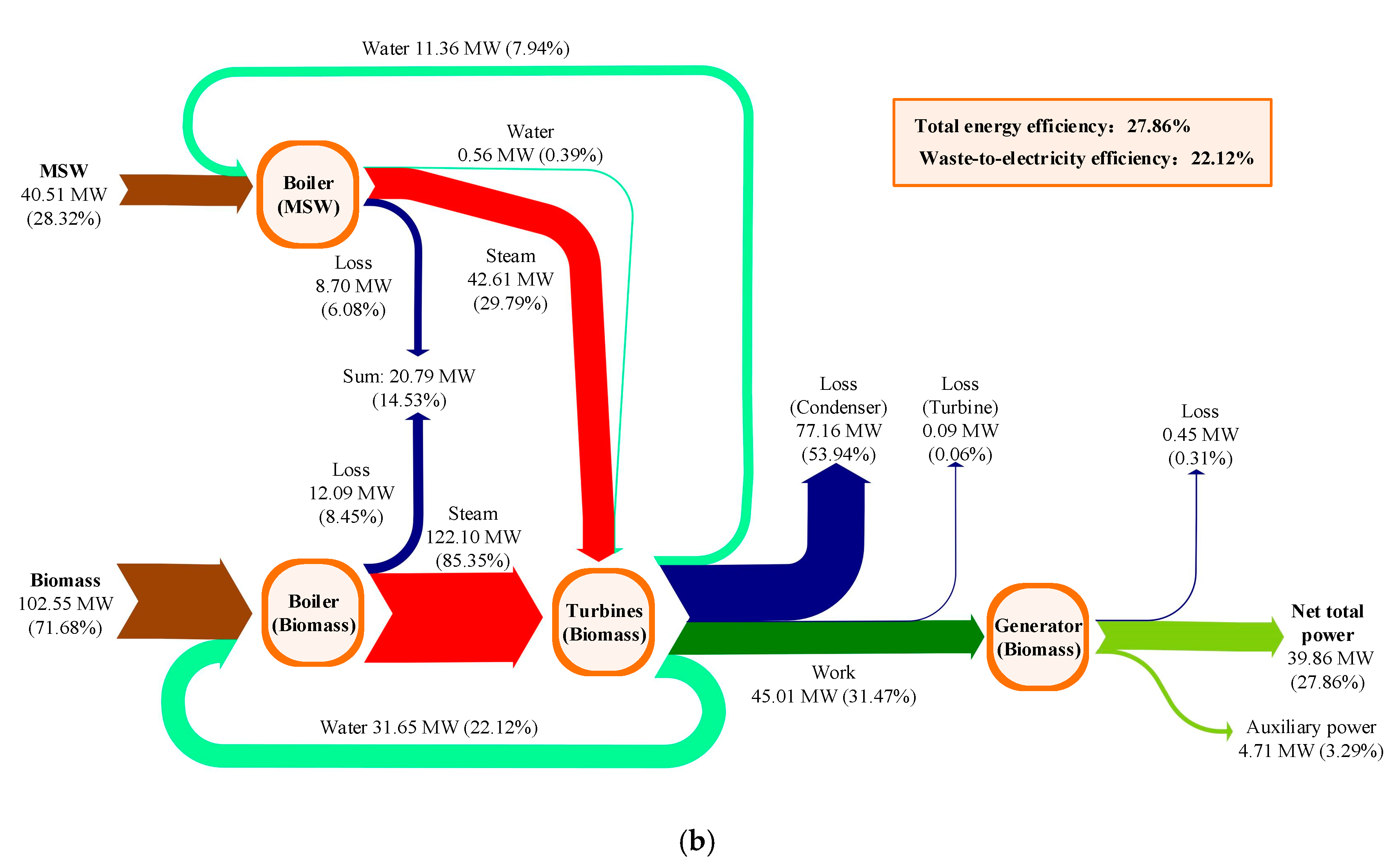
The detailed energy flows in the two schemes are displayed in Figure 4. The feedstocks (biomass and MSW) provide the energy inputs of the two schemes, which are identical for the two schemes. In the separate scheme, the superheated steam of 42.61 MW from the WtE boiler goes into the turbine to produce work, and the extraction steam of 4.08 MW from the turbine is conveyed to warm the combustion air in the PAH2 and SAH. In the integrated scheme, 42.61-MW energy from the WtE boiler is delivered to the turbine of the biomass power section for power generation. Meanwhile, the feedwater derived from the biomass power section is sent to preheat the air into the WtE boiler, then flows into the WtE boiler. Since the total steam flow rate into the condensers declines by 0.83 t/h after the incorporation, the overall energy loss of the condensers decreases from 77.64 MW to 77.16 MW. Besides, the energy losses of the turbines and the boilers remain unchanged in the two schemes. Generally, the integrated scheme generates an additional power of 0.66 MW compared to the separate scheme.

4.3. Exergy Analysis

Exergy is regarded as the maximum useful work that can be utilized during the energy conversion process [30], and the exergy analysis can provide extra information as compared to the energy analysis [31].
The exergy of the feedstock ( E X f , kW) can be estimated as [32]:
E X f = ( m f / 3.6 ) × q f , net × ( 1.0064 + 0.1519 × w ( H ) w ( C ) + 0.0616 × w ( O ) w ( C ) + 0.0429 × w ( N ) w ( C ) )
where m f is the feedstock (MSW or biomass) flow rate, t/h; q f , net is the lower heating value of the feedstock, kJ/kg; and w ( H ) , w ( C ) , w ( O ) , and w ( N ) are the contents of hydrogen, carbon, oxygen, and nitrogen in the feedstock.
The waste-to-electricity exergy efficiency ( η ex , w ) and the total exergy efficiency ( η ex , tot ) are formulated as:
η ex , w = P w E X w
η ex , tot = P tot E X b + E X w
where E X w and E X b are the exergy of the MSW and the exergy of the biomass, kW.
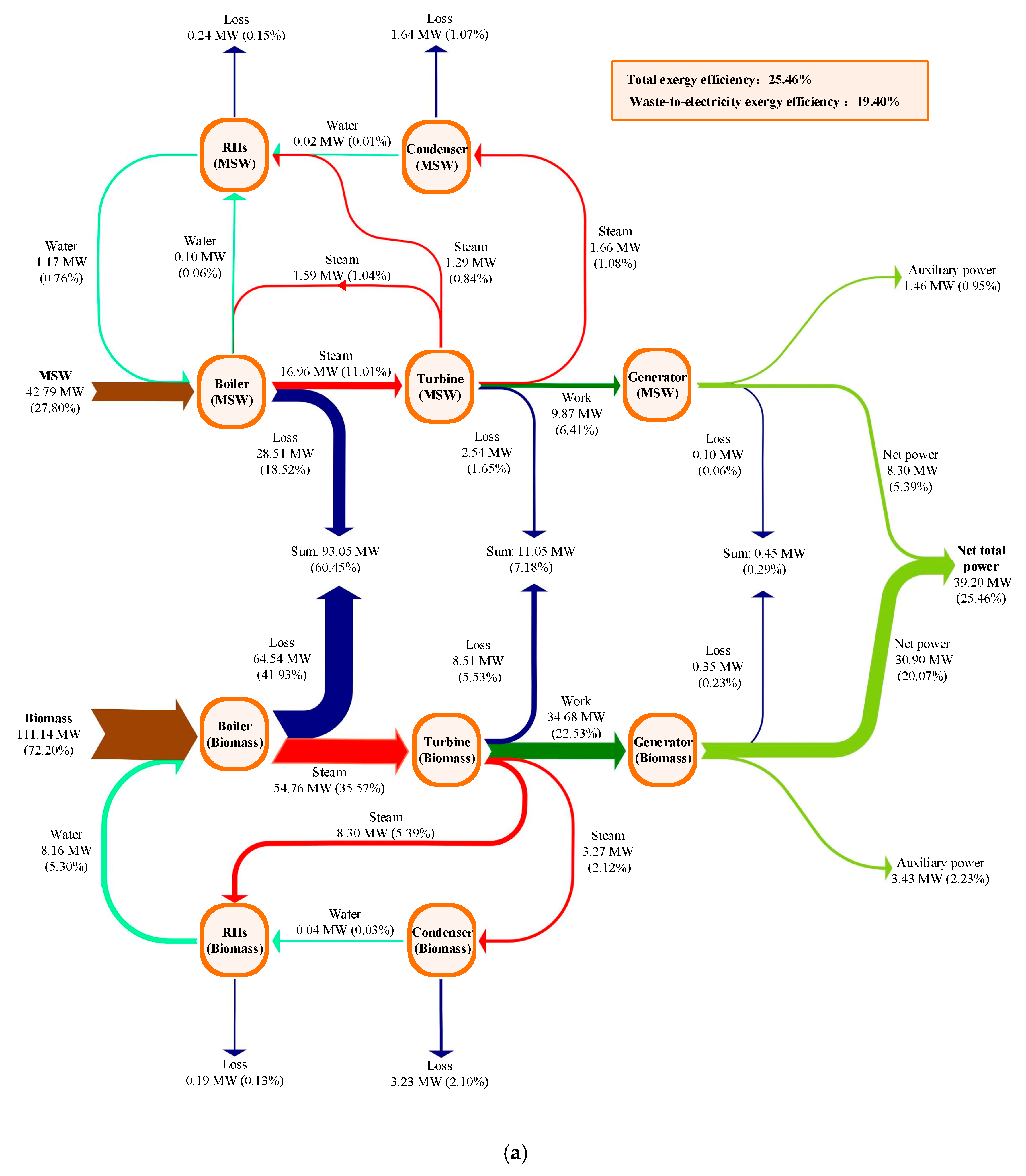
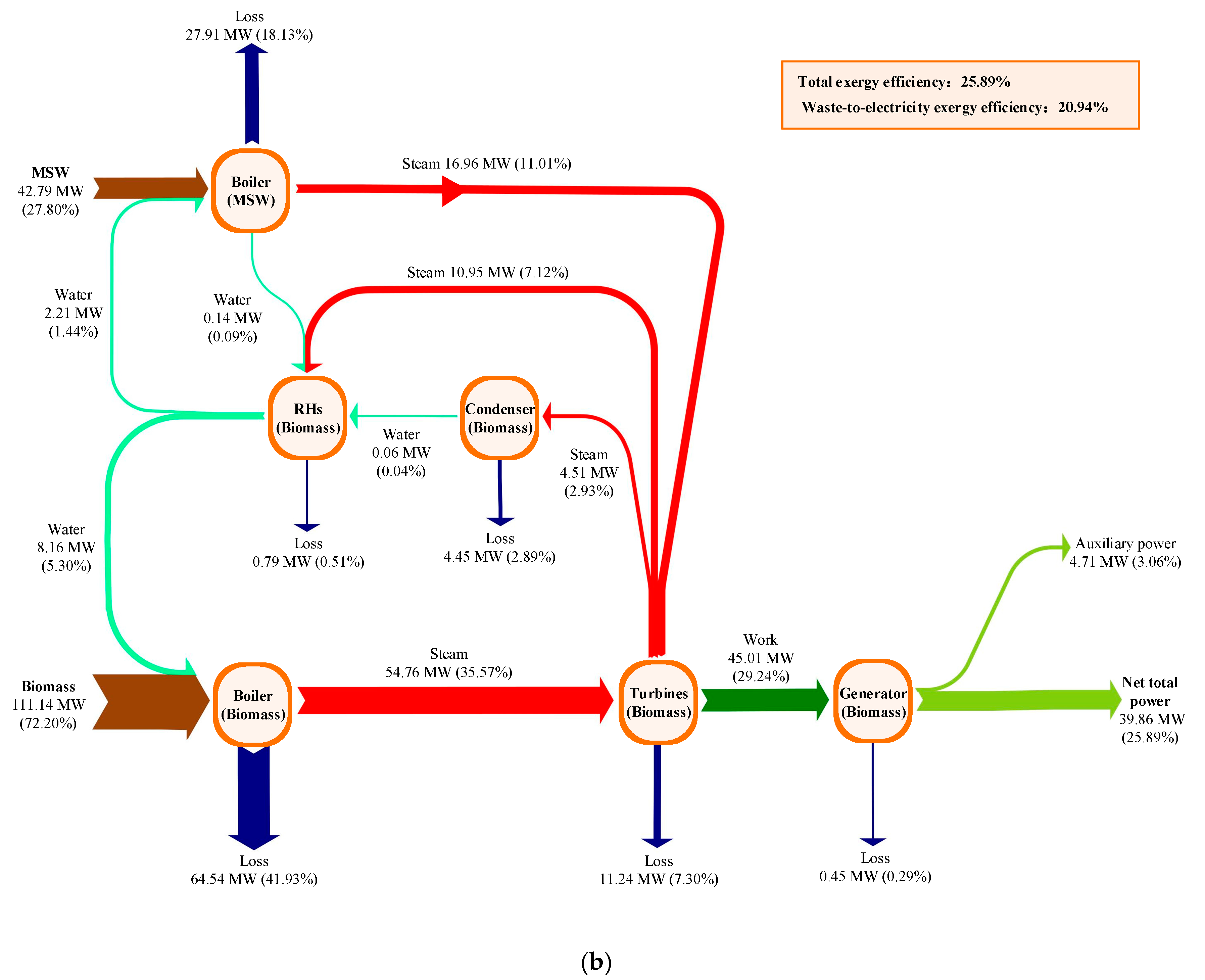
The exergy flows of the two schemes were explored, as illustrated in Figure 5, where the exergy inflows, exergy outflows, and exergy losses of the main components are indicated. In the separate scheme, the MSW exergy (42.79 MW) and the biomass exergy (111.14 MW) enter into the WtE boiler and the biomass-fired boiler, and the boilers offer exergy (steam) to the steam cycles of the two reference plants, contributing a total exergy output (electricity) of 39.20 MW. In the integrated scheme, a portion of the feedwater is delivered from the DEA outlet into the PAH2 and SAH2 to warm the air, and then, the condensate enters into the WtE boiler; thereby, more steam extractions into RH3–6 will be needed for feedwater heating. Moreover, partial feedwater of the biomass power section is used to preheat the air in the PAH1 and SAH2; thus, the steam extraction into the RH6 will be augmented. Attributed to the incorporation, the net total exergy output (electricity) is raised to 39.86 MW, which is 0.66 MW larger than that of the separate scheme. In addition, the total exergy loss in the boilers declines from 93.05 MW to 92.45 MW, which is mainly because the temperature differences in the PAHs and SAHs drop. The total exergy loss of the condensers dwindles by 0.42 MW due to the decrease of the steam into the condensers. The total exergy loss of the turbines is raised from 11.05 MW to 11.24 MW, and the total exergy loss of the RHs increases from 0.43 MW to 0.79 MW. The exergy losses of other components have no obvious changes. Therefore, the total exergy loss of the integrated scheme diminishes from 114.73 MW to 114.07 MW. Caused by the integration, the waste-to-electricity exergy efficiency is promoted from 19.40% to 20.94%, and the total exergy efficiency is enhanced from 25.46% to 25.89%.

5. Economic Analysis

An economic analysis, which considers both the cash inflows and cash outflows within the duration of a project, was conducted to offer another view on the feasibility of the novel concept. Under the condition that the expenses and earnings of the biomass power section were deemed as unchanged, the WtE section was solely studied. Table 11 presents the basic economic data for the evaluation. The reference WtE plant was constructed in China with a unit capital cost of 56,500 USD/t, and the electricity sale and waste disposal fee are the main sources of cash inflows.
Due to the novel solution, some components in the WtE section and the biomass power section are removed, retrofitted, or added. The capital costs of the changed equipment were calculated by the methods shown in Table 12, and the results are given in Table 13. Several components (turbine, condenser, stack, etc.) of the WtE plant are removed after the integration; thereby, the capital costs of 6649.68 thousand USD can be saved. As some extra components (PRV and AP) are installed for the hybrid configuration, an additional capital cost of 0.83 thousand USD is needed. Moreover, the PAH and SAH of the WtE boiler and the turbine and generator of the biomass power section are remolded for the incorporation; the relative capital cost will augment by 4407.10 thousand USD. Consequently, the total capital cost of the WtE section diminishes by 2241.74 thousand USD due to the new design.
To examine the economic feasibility, two indicators have been adopted, the dynamic payback period (DPP, year) and the net present value (NPV, USD) [43]:
y = 1 D P P C in C out ( 1 + r dis ) y = 0
N P V = y = 1 b C in C out ( 1 + r dis ) y
where C in is the cash inflow, USD, C out is the cash outflow, USD, y is the year number in the plant lifetime, b is the plant lifetime, year, and r dis is the discount rate.
As shown in Table 14, the total capital cost of the WtE section is cut down by 2.24 million USD due to the proposal; meanwhile, the operational cost decreases from 2.83 million USD to 2.60 million USD. Since the feedstock (MSW) flow rate is invariable, the MSW disposal capacities in the two schemes are both 150,000 t, and the waste disposal fee remains fixed. Induced by the hybridization, the electricity supply is improved from 59.76 GW·h to 64.52 GW·h; thereby, the revenue of electricity sales increase by 0.46 million USD. Hence, the dynamic payback period of the WtE section declines from 8.18 years to 5.37 years, and the net present value grows from 5.26 million USD to 10.28 million USD.

6. Sensitivity Analysis

Regarding the operation of the hybrid system, the dominating factors are the conditions of the biomass-fired boiler and the WtE boiler. The loads of the two boilers basically impact the live steam parameters; thereby, the performance of the steam cycle is mostly determined. The boiler loads are mainly dependent on the fuel qualities and quantities. Normally, while the fuel qualities/types of the two boilers change in limited ranges, the boiler loads can be adjusted by regulating the fuel feed rates. On the condition that the boiler loads are constant, the live steam parameters of the two boilers can be nearly maintained identical. Hence, a sensitivity analysis has been undertaken to check how the boiler loads affect the performance of the hybrid system. However, the effects of the fuel types or qualities were not discussed. Besides, the fuel types or qualities are necessary to remain relatively stable for the two boilers during operation. If the fuel types or qualities are far from the design ones, the two boilers cannot work well or may even shut down, especially the WtE boiler.
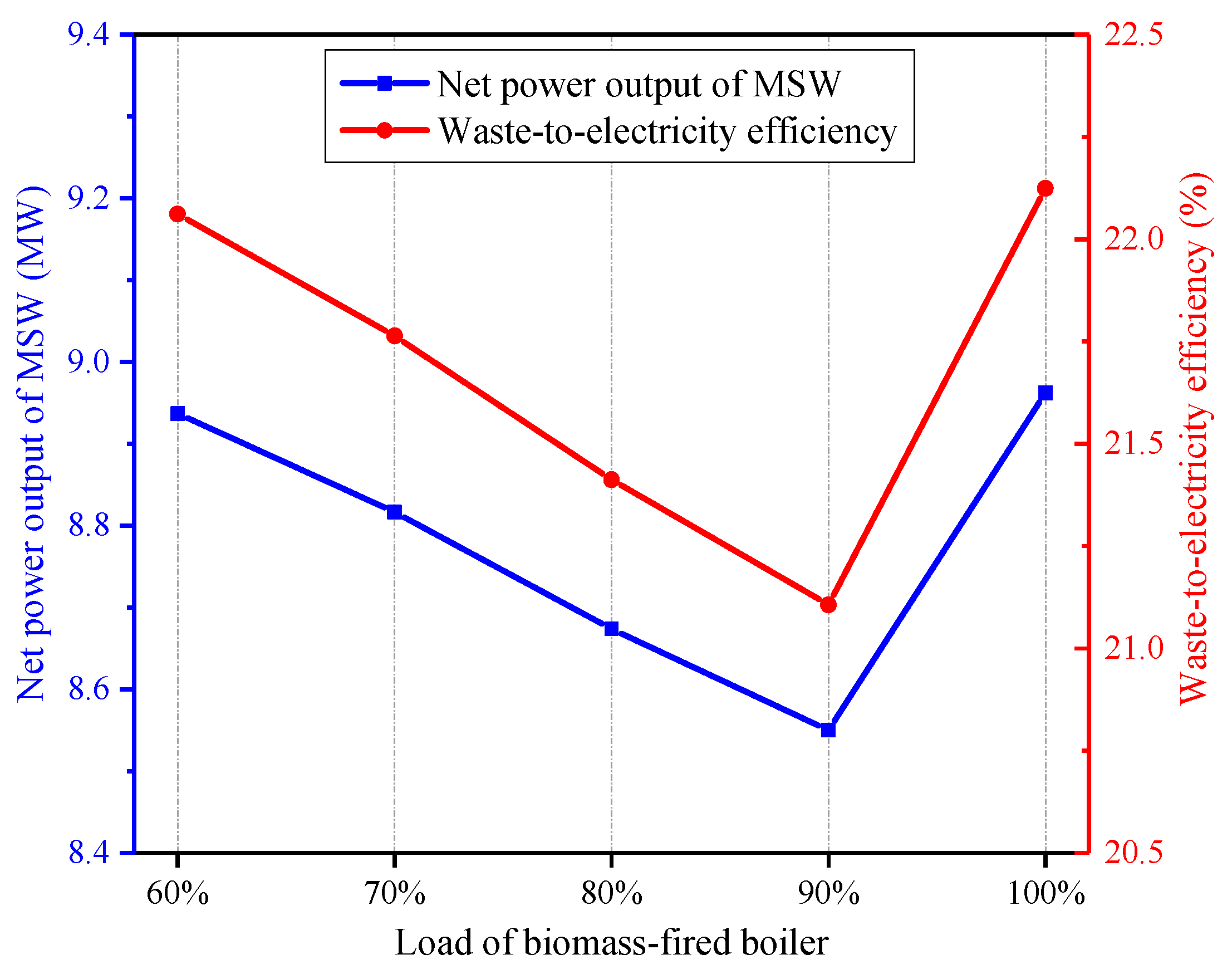
Figure 6 displays the influence of the biomass-fired boiler load on the performance of the hybrid system. It can be seen that the waste-to-electricity efficiency decreases when the biomass-fired boiler load declines from 100% to 90%, but then, the waste-to-electricity efficiency grows along with the decrement of the load. This is chiefly because the temperature of the feedwater that heats the combustion air of the WtE boiler in the PAH2 and SAH2 diminishes with the descending biomass-fired boiler load, and the feedwater from the RH2 outlet is employed for air preheating once the biomass-fired boiler load ranges from 60% to 90%. As a result, the power consumption of the FWP1 increases, which reduces the net power output of the MSW. Besides, with the decrease of the biomass-fired boiler load condition (from 90% to 60%), the outlet air temperatures of the PAH1/SAH1will be higher; thereby, more low-grade heat from the biomass-fired section can be used to warm the air instead of the high-grade heat, which is favorable to producing more power.
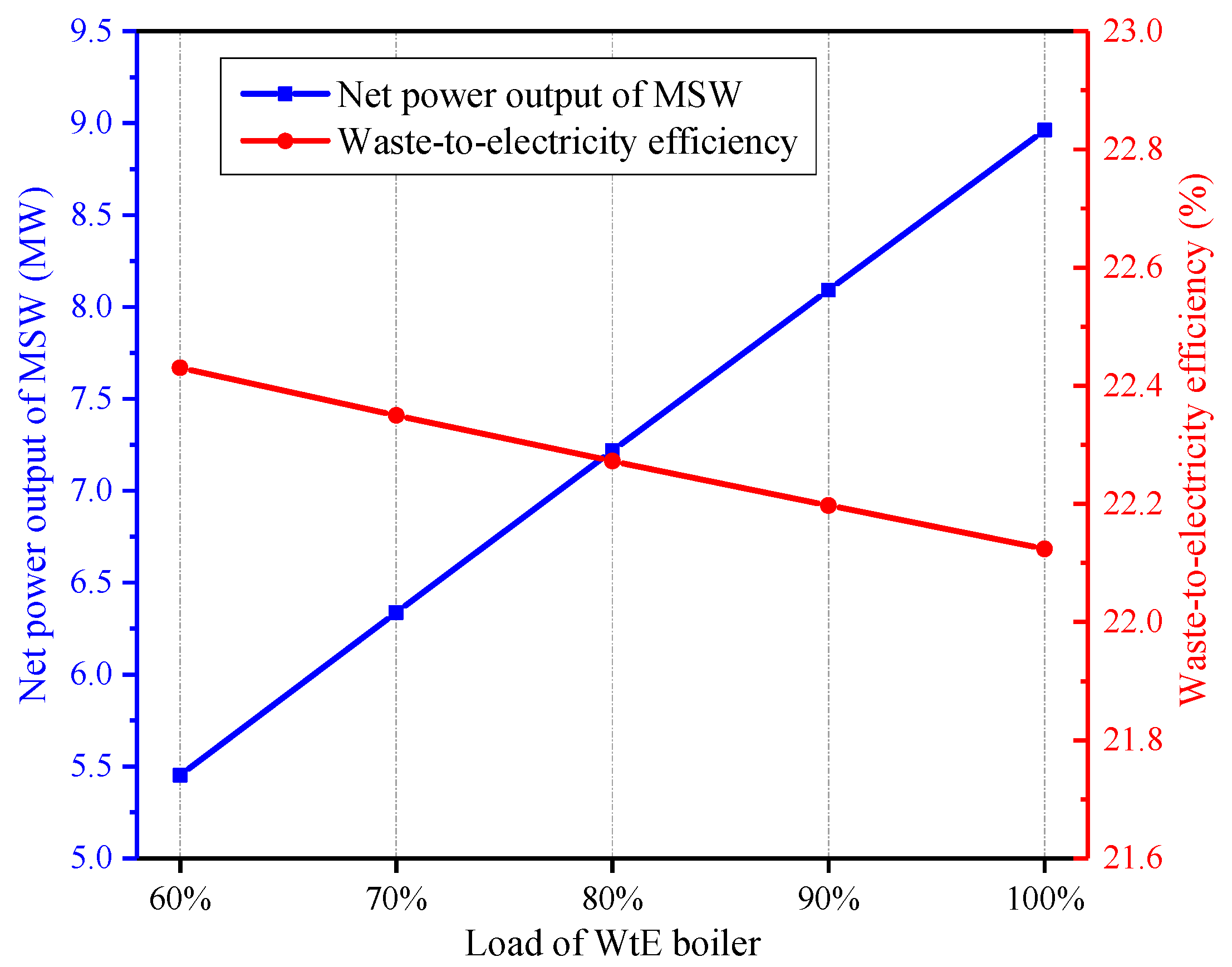
The performance of the hybrid system varying with the WtE boiler load is presented in Figure 7. With the decrease of the WtE boiler load, the DEA inlet steam pressure and the feedwater temperature into the PAH2/SAH2 dwindle. Furthermore, the air temperature between the PAH1 and PAH2 (or SAH1 and SAH2) gets larger, leading to utilizing more low-grade heat from the biomass power section. As a consequence, while the WtE boiler load falls, the net power output of the MSW drops, but the waste-to-electricity efficiency rises slightly.

7. Conclusions

For improving the energy utilization efficiency of the waste-to-energy process, this paper developed an innovative design that combines a waste-to-energy plant with a biomass-fired power plant based on the steam cycle integration. According to the novel concept, the superheated steam generated by the waste-to-energy boiler enters into the turbine of the biomass power section for power production. Meanwhile, the air fed into the waste-to-energy boiler is warmed by the feedwater from the biomass power section and the saturated steam from the waste-to-energy boiler, and the biomass power section supplies feedwater for the waste-to-energy boiler. To assess the new design thermodynamically and economically, the separate schemes and the integrated scheme were simulated based on a 35-MW biomass-fired power plant and a 500-t/d waste-to-energy plant. When the feedstock (biomass and municipal solid waste) flow rates are constant, the net power output of municipal solid waste is promoted by 0.66 MW, and the waste-to-electricity efficiency increases from 20.49% to 22.12%. Energy and exergy analyses were implemented to uncover the root cause of efficiency-boosting. The decrease of steam into the condensers is the main cause of energy loss reduction. On the other hand, the exergy losses of the boilers and the condensers are diminished significantly, induced by the decreased temperature differences of the air preheaters and the decline of the steam into the condensers. The economic analysis results indicate that the dynamic payback period of the waste-to-energy section diminishes from 8.18 years to 5.37 years, and the net present value is raised by 5.02 million USD. Besides, the performance of the new design was investigated under various boiler loads. In summary, the proposal is extremely feasible from the viewpoints of thermodynamics and economics. The current research has been one of the first attempts to integrate the energy conversions of municipal solid waste and biomass, which lays the groundwork for future research.

Author Contributions

Conceptualization, P.P. and H.C.; data curation, M.Z., H.C. and X.S.; formal analysis, P.P. and M.Z.; funding acquisition, G.X. and H.C.; investigation, P.P., M.Z. and X.S.; software, M.Z.; supervision, G.X. and T.L.; writing—original draft, P.P. and M.Z.; and writing—review and editing, G.X. and H.C. All authors have read and agreed to the published version of the manuscript.

Funding

This work was supported by the National Nature Science Fund of China (No. 51806062) and the Fundamental Research Funds for the Central Universities (No. 2020MS006).

Conflicts of Interest

The authors declare no conflict of interest.

References

  1. Ning, C.; You, F. Data-driven Wasserstein distributionally robust optimization for biomass with agricultural waste-to-energy network design under uncertainty. Appl. Energy 2019, 255, 113857. [Google Scholar] [CrossRef]
  2. Martínez-Guido, S.I.; Ríos-Badrán, I.M.; Gutiérrez-Antonio, C.; Ponce-Ortega, J.M. Strategic planning for the use of waste biomass pellets in Mexican power plants. Renew. Energy 2019, 130, 622–632. [Google Scholar] [CrossRef]
  3. Bermúdez, C.A.; Porteiro, J.; Varela, L.G.; Chapela, S.; Patiño, D. Three-dimensional CFD simulation of a large-scale grate-fired biomass furnace. Fuel Process. Technol. 2020, 198, 106219. [Google Scholar] [CrossRef]
  4. Situmorang, Y.A.; Zhao, Z.; Yoshida, A.; Abudula, A.; Guan, G. Small-scale biomass gasification systems for power generation (<200 kW class): A review. Renew. Sustain. Energy Rev. 2020, 117, 109486. [Google Scholar]
  5. Osman, A.I.; Abdelkader, A.; Farrell, C.; Rooney, D.; Morgan, K. Reusing, recycling and up-cycling of biomass: A review of practical and kinetic modelling approaches. Fuel Process. Technol. 2019, 192, 179–202. [Google Scholar] [CrossRef]
  6. Nunes, L.J.R.; Causer, T.P.; Ciolkosz, D. Biomass for energy: A review on supply chain management models. Renew. Sustain. Energy Rev. 2020, 120, 109658. [Google Scholar] [CrossRef]
  7. Zhu, Y.; Liang, J.; Yang, Q.; Zhou, H.; Peng, K. Water use of a biomass direct-combustion power generation system in China: A combination of life cycle assessment and water footprint analysis. Renew. Sustain. Energy Rev. 2019, 115, 109396. [Google Scholar] [CrossRef]
  8. Liu, D.; Liu, M.; Xiao, B.; Guo, X.; Niu, D.; Qin, G.; Jia, H. Exploring biomass power generation’s development under encouraged policies in China. J. Clean. Prod. 2020, 258, 120786. [Google Scholar] [CrossRef]
  9. Yuan, J.; Luo, X.; Ding, X.; Liu, C.; Li, C. Biomass power generation fuel procurement and storage modes evaluation: A case study in Jilin. Renew. Sustain. Energy Rev. 2019, 111, 75–86. [Google Scholar] [CrossRef]
  10. Mandø, M. Direct combustion of biomass. In Biomass Combustion Science, Technology and Engineering; Rosendahl, L., Ed.; Woodhead Publishing, 2013; Available online: https://www.sciencedirect.com/science/article/pii/B9780857091314500042 (accessed on 21 August 2020).
  11. Vamvuka, D.; Loukakou, E.; Sfakiotakis, S.; Petrakis, E. The impact of a combined pre-treatment on the combustion performance of various biomass wastes and their blends with lignite. Acta 2020, 688, 178599. [Google Scholar] [CrossRef]
  12. Chen, G.; Wang, X.; Li, J.; Yan, B.; Wang, Y.; Wu, X.; Velichkova, R.; Cheng, Z.; Ma, W. Environmental, energy, and economic analysis of integrated treatment of municipal solid waste and sewage sludge: A case study in China. Sci. Total Environ. 2019, 647, 1433–1443. [Google Scholar] [CrossRef] [PubMed]
  13. Guo, Y.; Glad, T.; Zhong, Z.; He, R.; Tian, J.; Chen, L. Environmental life-cycle assessment of municipal solid waste incineration stocks in Chinese industrial parks. Resour. Conserv. Recycl. 2018, 139, 387–395. [Google Scholar] [CrossRef]
  14. Singh, K.; Hachem-Vermette, C. Influence of mixed-use neighborhood developments on the performance of waste-to-energy CHP plant. Energy 2019, 189, 116172. [Google Scholar] [CrossRef]
  15. Lombardi, L.; Carnevale, E.; Corti, A. A review of technologies and performances of thermal treatment systems for energy recovery from waste. Waste Manag. 2015, 37, 26–44. [Google Scholar] [CrossRef]
  16. Zhang, H.; Yu, S.; Shao, L.; He, P. Estimating source strengths of HCl and SO2 emissions in the flue gas from waste incineration. J. Environ. Sci.-China 2019, 75, 370–377. [Google Scholar] [CrossRef]
  17. Xu, H.; Lin, W.Y.; Dal Magro, F.; Li, T.; Py, X.; Romagnoli, A. Towards higher energy efficiency in future waste-to-energy plants with novel latent heat storage-based thermal buffer system. Renew. Sustain. Energy Rev. 2019, 112, 324–337. [Google Scholar] [CrossRef]
  18. Bogale, W.; Viganò, F. A Preliminary Comparative Performance Evaluation of Highly Efficient Waste-to-Energy Plants. Energy Procedia 2014, 45, 1315–1324. [Google Scholar] [CrossRef] [Green Version]
  19. Martin, J.J.E.; Koralewska, R.; Wohlleben, A. Advanced solutions in combustion-based WtE technologies. Waste Manag. 2015, 37, 147–156. [Google Scholar] [CrossRef]
  20. Liuzzo, G.; Verdone, N.; Bravi, M. The benefits of flue gas recirculation in waste incineration. Waste Manag. 2007, 27, 106–116. [Google Scholar] [CrossRef]
  21. Strobel, R.; Waldner, M.H.; Gablinger, H. Highly efficient combustion with low excess air in a modern energy-from-waste (EfW) plant. Waste Manag. 2018, 73, 301–306. [Google Scholar] [CrossRef]
  22. Main, A.; Maghon, T. Concepts and experiences for higher plant efficiency with modern advanced boiler and incineration technology. In Proceedings of the 18th Annual North American Waste-to-Energy Conference, Orlando, FL, USA, 11–13 May 2010. [Google Scholar]
  23. Hulgaard, T.; MSc, I.S. Integrating waste-to-energy in Copenhagen, Denmark. Proc. Inst. Civ. Eng.-Civ. Eng. 2018, 171, 3–10. [Google Scholar] [CrossRef] [Green Version]
  24. Behzadi, A.; Gholamian, E.; Houshfar, E.; Habibollahzade, A. Multi-objective optimization and exergoeconomic analysis of waste heat recovery from Tehran’s waste-to-energy plant integrated with an ORC unit. Energy 2018, 160, 1055–1068. [Google Scholar] [CrossRef]
  25. Consonni, S.; Silva, P. Off-design performance of integrated waste-to-energy, combined cycle plants. Appl. Eng. 2007, 27, 712–721. [Google Scholar] [CrossRef]
  26. Poma, C.; Verda, V.; Consonni, S. Design and performance evaluation of a waste-to-energy plant integrated with a combined cycle. Energy 2010, 35, 786–793. [Google Scholar] [CrossRef]
  27. Mendecka, B.; Lombardi, L.; Gładysz, P.; Stanek, W. Exergo-Ecological Assessment of Waste to Energy Plants Supported by Solar Energy. Energies 2018, 11, 773. [Google Scholar] [CrossRef] [Green Version]
  28. Chen, H.; Zhang, M.; Xue, K.; Xu, G.; Yang, Y.; Wang, Z.; Liu, W.; Liu, T. An innovative waste-to-energy system integrated with a coal-fired power plant. Energy 2020, 194, 116893. [Google Scholar] [CrossRef]
  29. STEAG Energy Services, EBSILON Professional Documentation; 2020; Available online: https://www.ebsilon.com/en/ (accessed on 21 August 2020).
  30. Liu, Z.; Liu, B.; Guo, J.; Xin, X.; Yang, X. Conventional and advanced exergy analysis of a novel transcritical compressed carbon dioxide energy storage system. Energy Convers. Manag. 2019, 198, 111807. [Google Scholar] [CrossRef]
  31. Mahabadipour, H.; Srinivasan, K.K.; Krishnan, S.R. An exergy analysis methodology for internal combustion engines using a multi-zone simulation of dual fuel low temperature combustion. Appl. Energy 2019, 256, 113952. [Google Scholar] [CrossRef]
  32. Zhou, J.; Ling, P.; Su, S.; Xu, J.; Xu, K.; Wang, Y.; Hu, S.; Zhu, M.; Xiang, J. Exergy analysis of a 1000 MW single reheat advanced supercritical carbon dioxide coal-fired partial flow power plant. Fuel 2019, 255, 115777. [Google Scholar] [CrossRef]
  33. Zhao, X.; Jiang, G.; Li, A.; Wang, L. Economic analysis of waste-to-energy industry in China. Waste Manag. 2016, 48, 604–618. [Google Scholar] [CrossRef]
  34. Xiangba, Z. Cost analysis of waste incineration-power generation projects. Environ. Sanit. Eng. 2014, 22, 57–60. (In Chinese) [Google Scholar]
  35. National Development and Reform-Commission. The Notice on Improving Price Policies of WtE Plants; Beijing, China, 2012. (In Chinese). Available online: http://www.nea.gov.cn/2014-09/29/c_133682178.htm (accessed on 21 August 2020).
  36. Ye, C. Research on the Key Issue of Coal Partial Gasification Technology; Zhejiang University: Hangzhou, China, 2018. (In Chinese) [Google Scholar]
  37. Han, Y. Collaborative Optimization of Energy Utilization and Pollutant Emission Reduction in Cold End of Boiler in Coal-Fired Power Generation System; North China Electric Power University: Beijing, China, 2018. (In Chinese) [Google Scholar]
  38. Electric Power Planning and Engineering-Institute. Quota Design Reference Cost Indicators for Thermal Power Projects (2017 Level); China Electric Power Press: Beijing, China, 2018. (In Chinese) [Google Scholar]
  39. Ogorure, O.J.; Oko, C.O.C.; Diemuodeke, E.O.; Owebor, K. Energy, exergy, environmental and economic analysis of an agricultural waste-to-energy integrated multigeneration thermal power plant. Energy Convers. Manag. 2018, 171, 222–240. [Google Scholar] [CrossRef]
  40. Lian, Z.T.; Chua, K.J.; Chou, S.K. A thermoeconomic analysis of biomass energy for trigeneration. Appl. Energy 2010, 87, 84–95. [Google Scholar] [CrossRef]
  41. Zhang, C.; Liu, C.; Wang, S.; Xu, X.; Li, Q. Thermo-economic comparison of subcritical organic Rankine cycle based on different heat exchanger configurations. Energy 2017, 123, 728–741. [Google Scholar] [CrossRef]
  42. Owebor, K.; Oko, C.O.C.; Diemuodeke, E.O.; Ogorure, O.J. Thermo-environmental and economic analysis of an integrated municipal waste-to-energy solid oxide fuel cell, gas-, steam-, organic fluid- and absorption refrigeration cycle thermal power plants. Appl. Energy 2019, 239, 1385–1401. [Google Scholar] [CrossRef]
  43. Liu, M.; Zhang, X.; Ma, Y.; Yan, J. Thermo-economic analyses on a new conceptual system of waste heat recovery integrated with an S-CO2 cycle for coal-fired power plants. Energy Convers. Manag. 2018, 161, 243–253. [Google Scholar] [CrossRef]
Figure 1. Reference WtE plant.
Energies 13 04345 g001
Figure 2. Reference biomass-fired power plant.
Energies 13 04345 g002
Figure 3. Proposed WtE system integrated with a biomass-fired power plant.
Energies 13 04345 g003
Figure 4. Energy flows of the two schemes. (a) Separate scheme. (b) Integrated scheme.
Energies 13 04345 g004aEnergies 13 04345 g004b
Figure 5. Exergy flows of the two schemes. (a) Separate scheme. (b) Integrated scheme.
Energies 13 04345 g005aEnergies 13 04345 g005b
Figure 6. Effect of the biomass-fired boiler load on the performance of the integrated WtE system.
Energies 13 04345 g006
Figure 7. Effect of the WtE boiler load on the performance of the integrated WtE system.
Energies 13 04345 g007
Table 1. Basic parameters of the reference waste-to-energy (WtE) plant. MSW: municipal solid waste.
ItemUnitValue
Feedstock (MSW) flow ratet/h20.84
Lower heating valueMJ/kg7.00
Fuel energy inputMW40.51
Live steam
(into turbine)
Flow ratet/h48.60
PressureMPa3.90
Temperature°C395.0
Exhaust steam
(into condenser)
Flow ratet/h35.75
PressurekPa6.80
Temperature°C38.5
Exhaust gas temperature (out of boiler)°C190.0
Boiler capacity (heat absorbed by working fluid)MW37.47
Boiler efficiency%78.53
Net power outputMW8.30
Waste-to-electricity efficiency%20.49
Table 2. Parameters of the heat regeneration system in the reference WtE plant. DEA: deaerator and RH: regenerative heater.
ItemDEA (RH1)RH2
Extraction steamFlow rate (t/h)3.493.74
Pressure (MPa)0.270.08
Temperature (°C)195.492.8
Drain waterFlow rate (t/h)-3.74
Temperature (°C)-92.8
FeedwaterOutlet flow rate (t/h)51.139.74
Outlet temperature (°C)130.088.0
Table 3. Parameters of the air preheating system in the reference WtE plant. PAH: primary air heater and SAH: secondary air heater.
ItemPAHSAH
PAH1PAH2PAH3
Hot fluid (steam/water)Inlet pressure (MPa)4.541.314.541.31
Inlet flow rate (t/h)2.233.892.231.76
Inlet/outlet temperature (°C)225.3/104.3287.3/98.3258.0/225.3287.3/98.5
Cold fluid (air)Inlet flow rate (t/h)73.8473.8473.8430.17
Inlet/outlet temperature (°C)15.0/31.031.0/166.0166.0/220.015.0/166.0
Table 4. Basic parameters of the reference biomass-fired power plant.
ItemUnitValue
Feedstock (biomass) flow ratet/h39.13
Lower heating valueMJ/kg9.435
Fuel energy inputMW102.55
Live steam
(into turbine)
Flow ratet/h128.99
PressureMPa9.40
Temperature°C535.0
Exhaust steam
(into condenser)
Flow ratet/h91.80
PressurekPa4.90
Temperature°C32.5
Exhaust gas temperature (out of boiler)°C127.0
Boiler capacity (heat absorbed by working fluid)MW91.36
Boiler efficiency%89.10
Net power outputMW30.90
Biomass-to-electricity efficiency%30.13
Table 5. Parameters of the heat regeneration system in the reference biomass-fired power plant.
ItemRH1RH2DEA (RH3)RH4RH5RH6
Extraction steamFlow rate (t/h)7.885.833.645.045.809.00
Pressure (MPa)2.551.320.590.400.190.07
Temperature (°C)381.4353.5278.2190.5126.888.2
Drain waterFlow rate (t/h)7.8813.72-5.0410.8419.84
Temperature (°C)192.4158-118.488.232.5
FeedwaterOutlet flow rate (t/h)128.99128.99128.99111.67111.67111.67
Outlet temperature (°C)220.0187.4158.0139.3114.484.2
Table 6. Comparison of the simulation results and design data of the reference WtE plant.
ItemDesignCalculatedRelative Error (%)
Feedstock (MSW) flow rate (t/h)20.8420.840.00
Live steam
(into turbine)
Flow rate (t/h)48.6048.600.00
Pressure (MPa)3.903.900.00
Temperature (°C)395.0395.00.00
Exhaust steam
(into condenser)
Flow rate (t/h)35.6835.75+0.20
Pressure (MPa)6.806.800.00
Temperature (°C)38.538.50.00
Exhaust gas temperature (out of boiler) (°C)190.0190.00.00
Net power output (MW)8.318.30−0.12
Waste-to-electricity efficiency (%)20.5120.49−0.10
Table 7. Comparison of the simulation results and design data of the reference biomass-fired power plant.
ItemDesignCalculatedRelative Error (%)
Feedstock (biomass) flow rate (t/h)39.1339.130.00
Live steam
(into turbine)
Flow rate (t/h)128.99128.990.00
Pressure (MPa)9.409.400.00
Temperature (°C)535.0535.00.00
Exhaust steam
(into condenser)
Flow rate (t/h)91.6991.80+0.12
Pressure (MPa)4.904.900.00
Temperature (°C)32.532.50.00
Exhaust gas temperature (out of boiler) (°C)127.0127.00.00
Net power output (MW)30.9530.90−0.16
Biomass-to-electricity efficiency (%)30.1830.13−0.17
Table 8. Parameters of the air preheating system in the WtE section of the integrated scheme.
ItemPAHSAH
PAH1PAH2PAH3SAH1SAH2
Hot fluid (water/steam)Inlet pressure (MPa)0.890.874.540.890.87
Inlet flow rate (t/h)18.0436.292.237.3814.83
Inlet/outlet temperature (°C)93.2/35.0174.0/130.1258.0/225.393.2/35.0174.0/130.1
Cold fluid (air)Inlet flow rate (t/h)73.8473.8473.8430.1730.17
Inlet/outlet temperature (°C)15.0/74.174.1/166.0166.0/220.015.0/74.174.1/166.0
Table 9. Thermal performances of the two schemes.
ItemUnitSeparate SchemeIntegrated SchemeDifference
Feedstock (biomass) flow ratet/h39.1339.130.00
Feedstock (MSW) flow ratet/h20.8420.840.00
Gross total power outputMW44.1044.57+0.47
Total auxiliary powerMW4.904.71−0.19
Net total power outputMW39.2039.86+0.66
Net power output of biomassMW30.9030.900.00
Net power output of MSWMW8.308.96+0.66
Total energy efficiency%27.4027.86+0.46
Waste-to-electricity efficiency%20.4922.12+1.63
Table 10. Performance comparison of the WtE systems integrated with various power systems.
ItemRef [26]Ref [28]Current paper
Integrated schemeWtE + gas turbine combined cycleWtE + coal-fired power plantWtE + biomass-fired power plant
FuelsMSW + natural gasMSW + coalMSW + biomass
Waste-to-electricity efficiency of conventional WtE system (%)26.920.4920.49
Waste-to-electricity efficiency of integrated WtE system (%)33.829.6522.12
Improvement in waste-to-electricity efficiency due to integration (%)6.99.161.63
Table 11. Basic data for the economic analysis.
ItemUnitValue
Capital cost of reference WtE plant [33]million USD28.25
Operational cost of reference WtE plant [33]million USD2.83
Lifetime of WtE plant [34]Constructionyear2
Economicyear23
Annual operating time of WtE plant [34]h7200
Loan ratio [33]-70%
Loan term [33]year15
Interest rate [33]-6.15%
Discount rate [33]-12%
Disposal fee [33]USD/t9.65
Feed-in tariff [35]USD/(kW·h)0.97
Income tax rate in economic duration [34]1st–3rd year-0%
4th–6th year-12.5%
7th–23rd year-25.0%
Table 12. Capital cost estimation methods for the changed equipment.
Scaling Up Method
ComponentBasic Cost
(Million USD)
Basic Scale Scale Unit Scale Factor Reference
PAH, SAH0.788372m21[36,37]
Stack 10.654039.2t/h1[36,38]
Condenser4.2836000m21
Cooling tower17.0113000m21
Function method
Turbine C C T = 6000 × ( W T , nom ) 0.71 [39]
Pump C C P = 3540 × ( W P , nom ) 0.71
Generator C C G = 60 × ( P G , nom ) 0.95 [40]
DEA C C DEA = 6014 × ( m fw ) 0 . 7 [28]
RH log 10 ( C C RH ) = 4.8306 0.8509 × log 10 ( A ) + 0.3187 × [ log 10 ( A ) ] 2 [41]
PRV C C PRV = 37 × ( p in / p out ) 0.68 [42]
Note: C C T , C C P , C C G , C C DEA , C C RH , and C C PRV are the capital costs of the turbine, pump, generator, DEA, RH, and pressure reducing valve (PRV), USD; W T , nom is the nominal work output of the turbine, kW; W P , nom is the nominal work consumption of the pump, kW; P G , nom is the nominal power output of the generator, kW; m fw is the feedwater flow rate, kg/s; A is the heat transfer area, m2; and p in and p out are the inlet pressure and outlet pressure, kPa.
Table 13. Capital costs of the changed equipment. CP: condensate pump and AP: additional pump.
ComponentSeparate Scheme
(Thousand USD)
Integrated Scheme
(Thousand USD)
Difference
WtE sectionTurbine4111.07-−4111.07
Generator370.30-−370.30
Condenser118.78-−118.78
Circulating water pump146.65-−146.65
Cooling tower1504.68-−1504.68
CP9.02-−9.02
RH19.08-−19.08
DEA32.30-−32.30
Stack337.81-−337.81
PAH178.94297.13+118.19
SAH42.14119.01+76.87
Biomass power sectionTurbine10036.5113904.86+3868.34
Generator1221.931565.63+343.70
PRV-0.11+0.11
AP-0.72+0.72
Sum18129.2015887.46−2241.74
Table 14. Economic analysis results of the WtE section in the two schemes.
ItemSeparate SchemeIntegrated SchemeDifference
Total capital cost (million USD)28.2526.01−2.24
Operational cost (million USD)2.832.60−0.23
Annual amount of MSW disposal (103 t)1501500.00
Annual electricity supply (GW·h)59.7664.52+4.76
Annual revenue due to MSW disposal (million USD)1.451.450.00
Annual revenue due to electricity sale (million USD)5.776.23+0.46
Total annual revenue (million USD)7.227.68+0.46
Net present value (million USD)5.2610.28+5.02
Dynamic payback period (year) 8.185.37−2.81