Review

An Overview of HVDC Technology

by
Neville R. Watson
1,* and
Jeremy D. Watson
2
1
Department of Electrical & Computer Engineering, University of Canterbury, Private Bag 4800, Christchurch 8140, New Zealand
2
Department of Engineering, University of Cambridge, Trumpington St, Cambridge CB2 1PZ, UK
*
Author to whom correspondence should be addressed.
Energies 2020, 13(17), 4342; https://doi.org/10.3390/en13174342
Submission received: 18 July 2020 / Revised: 14 August 2020 / Accepted: 16 August 2020 / Published: 21 August 2020
(This article belongs to the Special Issue Multilevel Power Converters Control and Modulation Techniques)

Abstract

:
There is a growing use of High Voltage Direct Current (HVDC) globally due to the many advantages of Direct Current (DC) transmission systems over Alternating Current (AC) transmission, including enabling transmission over long distances, higher transmission capacity and efficiency. Moreover, HVDC systems can be a great enabler in the transition to a low carbon electrical power system which is an important objective in today’s society. The objectives of the paper are to give a comprehensive overview of HVDC technology, its development, and present status, and to discuss its salient features, limitations and applications.

Graphical Abstract

1. Introduction

Initially one of the reasons Alternating Current (AC) systems displaced Direct Current (DC) was because transformers allowed efficient conveyance of electricity by increasing the voltage for transmission and reducing the voltage to a level needed for utilization. Regardless of whether AC or DC is used there is always a need to use a voltage level appropriate for transmission distance and power being conveyed. High Voltage Direct Current (HVDC) transmission systems have significant advantages over AC transmission, as will be outlined later. The advances in solid-state devices, converter topology and control methods have accelerated the deployment of HVDC schemes in recent years. New converter topologies and control systems, and advances in semiconductor technology are increasing the benefits of HVDC systems. Therefore, in the foreseeable future the power system will continue to be AC with the penetration of DC systems increasing over time. Not only is DC well established for High Voltage (HV) systems, but there is increasing interest internationally in using DC also for medium and low voltage systems (MVDC and LVDC systems) [1].
A high penetration of DC systems into AC transmission and distribution networks will provide many benefits for the transition to a low carbon power system. This is particularly true when considering the connection of off-shore windfarms, where undersea cables are required [2,3]. Moreover, by connecting two AC power systems the best energy resources can be utilized, whereas when uncoupled, polluting generation resources would have to be used. A number of HVDC schemes were built to allow hydro generation to be exploited rather than using non-renewable thermal generation to meet the load requirement.
In the field of power electronics there are numerous converter technologies and a basic classification of AC/DC converters is given in Figure 1; however, only those more suitable for HVDC will be elaborated upon in this paper. In order to appreciate the historical developments in HVDC a brief review of HVDC technology is given in Section 2. Having set the scene, the historical background of HVDC systems is presented in Section 3. Some of the innovations made to the standard schemes are detailed in Section 4. Section 5 discusses areas where further developments are needed in HVDC systems. Finally, a few concluding comments are made in Section 6.
The development of HVDC systems is of paramount importance in achieving efficient conveyance of electricity, interconnecting different AC systems, as well as the integrating renewable energy resources [4,5]. The basics of converters are given in various power electronic textbooks [6,7,8,9,10,11,12,13], while references [14,15,16,17,18,19,20,21,22,23,24,25,26,27] are dedicated to various aspects of HVDC transmission systems. The review papers [28,29,30,31,32,33,34,35,36] are also insightful.

2. HVDC Technology Overview/Background

Before discussing the basic topologies, it is helpful to know some of the reasons HVDC is used [37]. These will be elaborated upon more when discussing the characteristics of the technology.

2.1. Advantages of HVDC

The main advantages of HVDC over High Voltage Alternating Current (HVAC) transmission are:
  • Asynchronous connection (can connect two AC systems of different frequency).
  • Overcoming technical limitations. HVDC can supply via a long cable system when an AC system cannot. This is due to the high cable capacitance causing a large capacitive current (reactive power flow) that leaves reduced current capacity for the transmission of real power when AC transmission is used.
  • No increase in short-circuit capacity (there is no need to upgrade protection equipment due to the link).
  • Controllable real power transfer (independent of Z, V & f). The ability supply power to any pre-specified criteria (the controller can be set to a variety of functions).
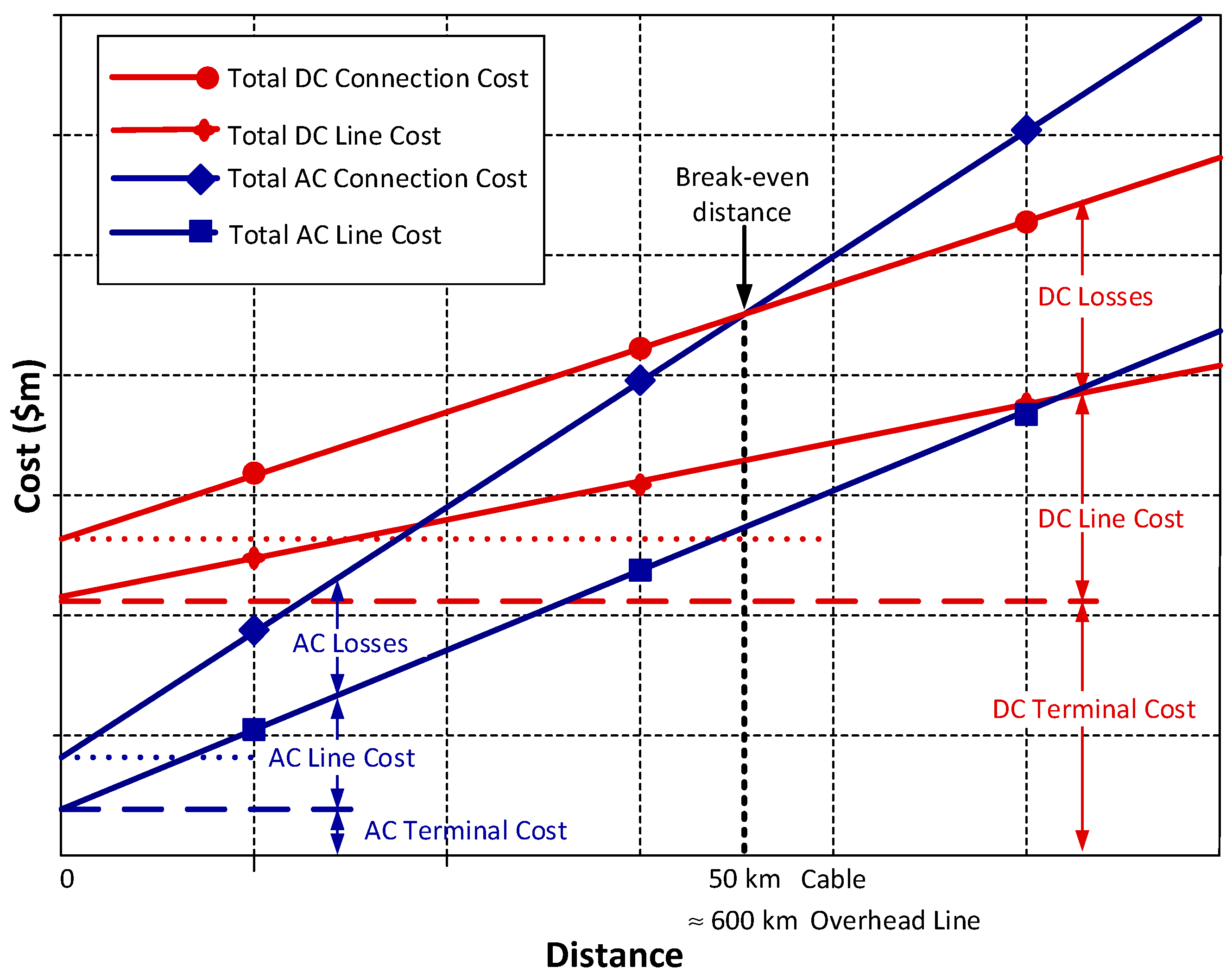
  • Lower losses (as shown in Figure 2) [36,38].
  • Higher power transfer for a given conductor.
  • No stability distance limitation.
  • The lack of reactive voltage drop means better voltage regulation for both heavy loading and light loading (no Ferranti effect).
  • Narrower right-of-way (better land use).
  • Higher power transfer for a given conductor.
  • Advanced control features can improve the stability of the AC systems and act as a fast generation reserve.

2.2. Power Electronic Switches

The fundamental component in an AC/DC converter is a switch can either be in the “on” (i.e., conducting) or “off” state [39]. The first switches used for HVDC systems were mercury-arc valves. These were then replaced by thyristors (shown in Figure 3a). A valve or thyristor is a switch in which turn-on is controlled by a gate pulse but turn-off naturally occurs when the current drops to zero. In other words, they cannot be turned-off by a gate signal and are hence referred to as Line commutated switches. Because of the voltage levels in HVDC schemes, one switch in the converter (termed valve for historical reasons) consisted of many thyristors in series.
By contrast, Insulated Gate Bipolar Transistors (IGBTs) have the ability to have both their turn-on and turn-off controlled by a gate signal and are termed self-commutated switches (Figure 3b). An anti-parallel free-wheeling diode is usually connected between the emitter and collector to allow bidirectional current flow through the combination. Gate turn-off thyristors (GTO), Metal-oxide-semiconductor (MOS)-controlled thyristors (MCT) and integrated gate-commutated thyristors (IGCT) are also self-commutated switches [40].
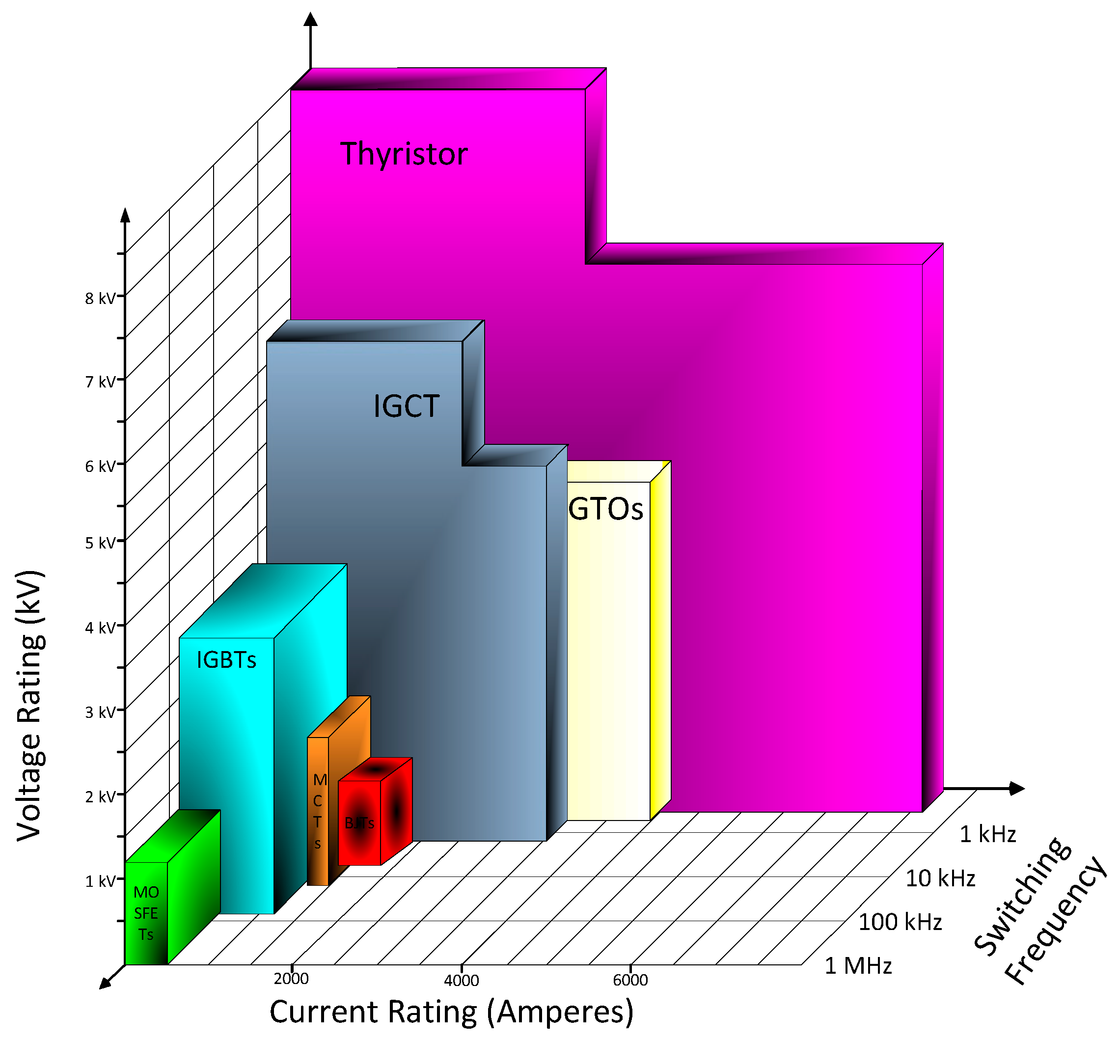
Any figure of device ratings, such as Figure 4 which displays the voltage current rating of the various devices, quickly becomes out-of-date due to improvements in technology; nonetheless, it is informative to see the comparative ratings of devices as it gives insight into their application.

2.3. Current Source Converters

Semiconductor devices are only required to have controllable turn-on as they naturally turn off when the current drops to zero due to turning on the next device on the same side of the converter. This commutation process depends on the AC system’s voltages and impedances and hence these devices are also frequently referred to as Line Commutated Converters (LCC) [17]. Figure 5 illustrates the DC voltage (Vdc0) that results from the converter conversion process. To match a level DC voltage (Vdc) a DC smoothing reactor is necessary [17]. This large DC reactor makes the converter current stiff, hence the term Current Source Converter (CSC).

2.4. Voltage Source Converters

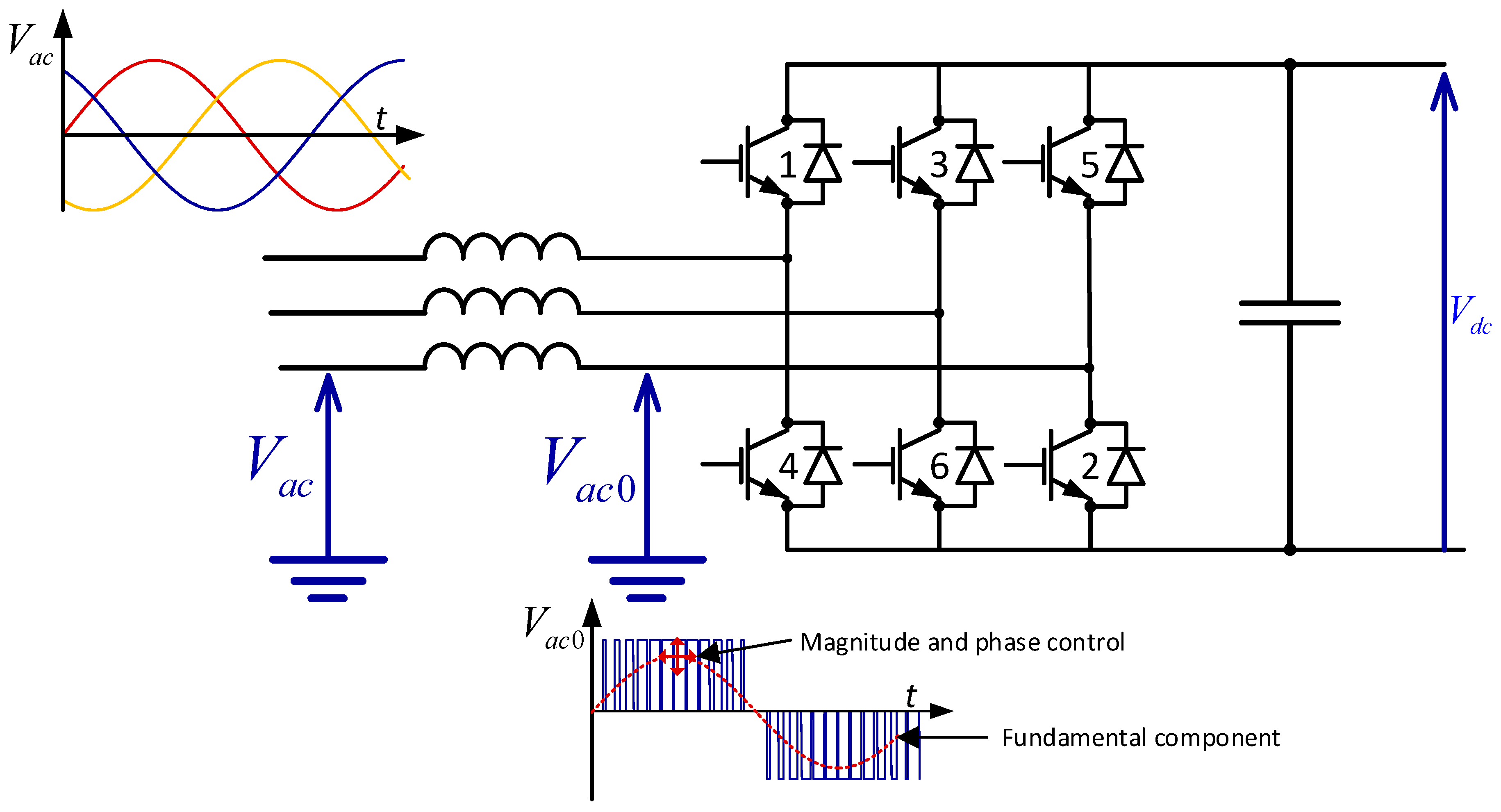
In a Voltage Source Converter (VSC) the capacitance on the DC side ensures that the voltage is stiff. To limit the current due to the mismatch between the AC system voltage and the voltage from the converter, an AC side inductor is used. This is illustrated in Figure 6. Ignoring the harmonic components, the real and reactive power conveyed to the AC system is given by:
P = V a c V a c 0 X sin ( δ )
Q = V a c X ( V a c 0 cos ( δ ) V a c )
where V a c and V a c 0 are the fundamental components of the AC terminal/grid voltage, and the AC voltage synthesized by the converter switching from the DC voltage, respectively. δ is the angle between these fundamental voltages on either side of the interfacing reactor. X is the reactance of the interfacing reactor. The switches for this type of converter must be self-commutated and have the ability to control the time instance of both turn-on and turn-off, which increases the flexibility of this converter.

2.5. Topologies

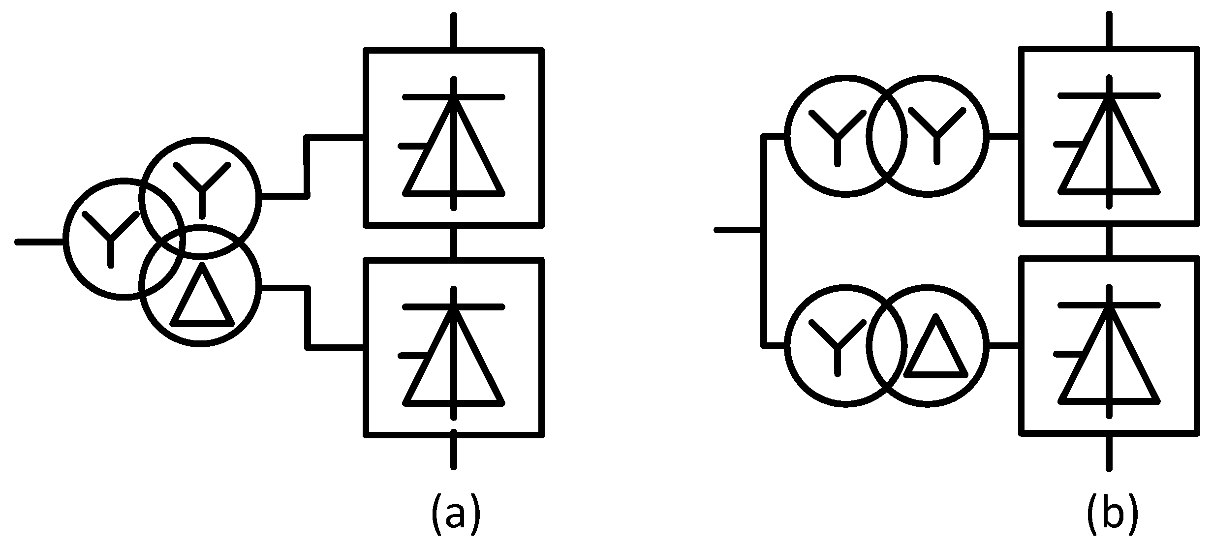
For current source converters, normally each converter comprises of two 6-bridges connected in series on the DC side and the AC is supplied from transformers with different winding configurations as shown in Figure 7. This gives harmonic cancellation of some harmonic orders and reduces the filtering requirements. Similarly, two 6-pulse VSCs (by using fundamental frequency switching) can be connected in series on the AC side and parallel on the DC side to form a 12-pulse VSC converter; however, the use of Pulse Width Modulation (PWM) and/or multilevel topologies are normally favoured.
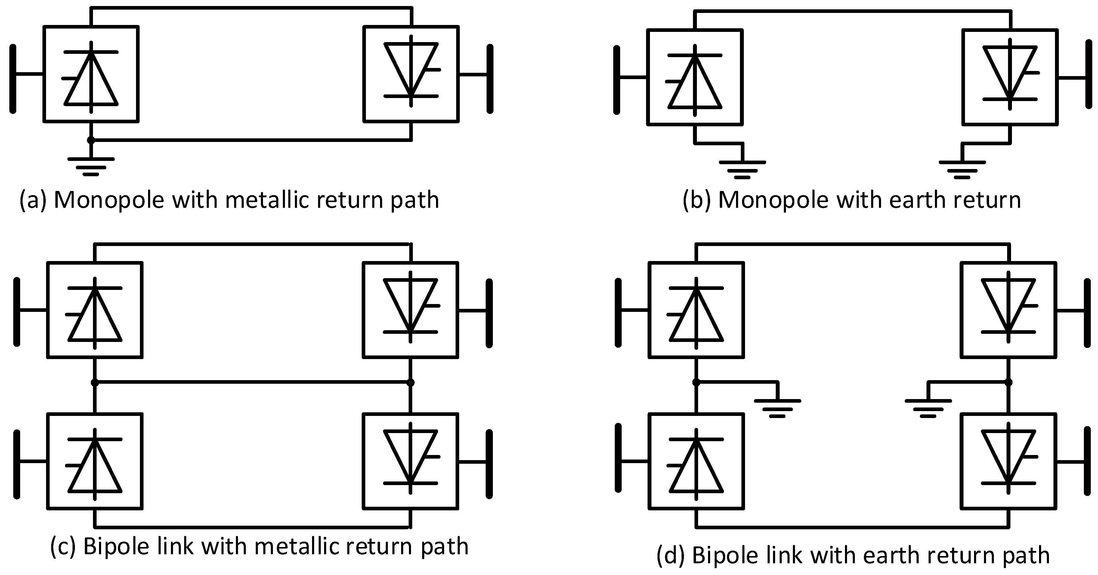
The simplest topology is a Back-to-Back (BTB) scheme as there is no transmission distance. This is used to connect two AC systems asynchronously when their frequencies differ or when the fault level precludes a more direct AC interconnector. Either CSCs or VSCs can be used for back-to-back HVDC links and any of the topologies shown in Figure 8, Figure 9, Figure 10 and Figure 11. The next in complexity is the monopole. The return path may be metallic (through a conductor) or to reduce costs, the earth or sea can be used as the return path. The problem with a monopole scheme is that any malfunction will see the loss of all the capacity. A bipole scheme, such as is illustrated in Figure 8, gives increased reliability as a fault in one pole will see only half the transmission capacity lost. The centre point of the converters may be connected via a conductor; however, since it is only used when a fault occurs, earth or sea electrodes are often used, and the return path is through the earth/sea. Figure 9 displays the current path for normal operation and for when forced and planned outages occur on a bipole HVDC scheme.
A number of configurations have been proposed for when the generation resources are far from the load and there is no local load. This removes the need for harmonic filter requirements. A unit-connected scheme is where there is a generator/transformer/converter connected as shown in Figure 10 and Group-connection reduces the cost by sharing a transformer(s) [41,42,43]. Although at one time there was considerable interest in these schemes, their efficiency, and the dependency of the DC voltage on the number of generators running (Unit-connected), has resulted in these schemes not being progressed.
The ability to exchange power between more than two places has resulted in multiterminal HVDC schemes [40]. The converters could be either be connected in series or parallel, as illustrated in Figure 11. One of the biggest challenges is the control and coordination of such schemes.

3. Comparison of Current Source and Voltage Source Converters

3.1. Introduction

Having seen the basic operation of current source and voltage source converters, the main distinctions will be elaborated upon, as these influence where each is best suited.

3.2. Current Source Converters

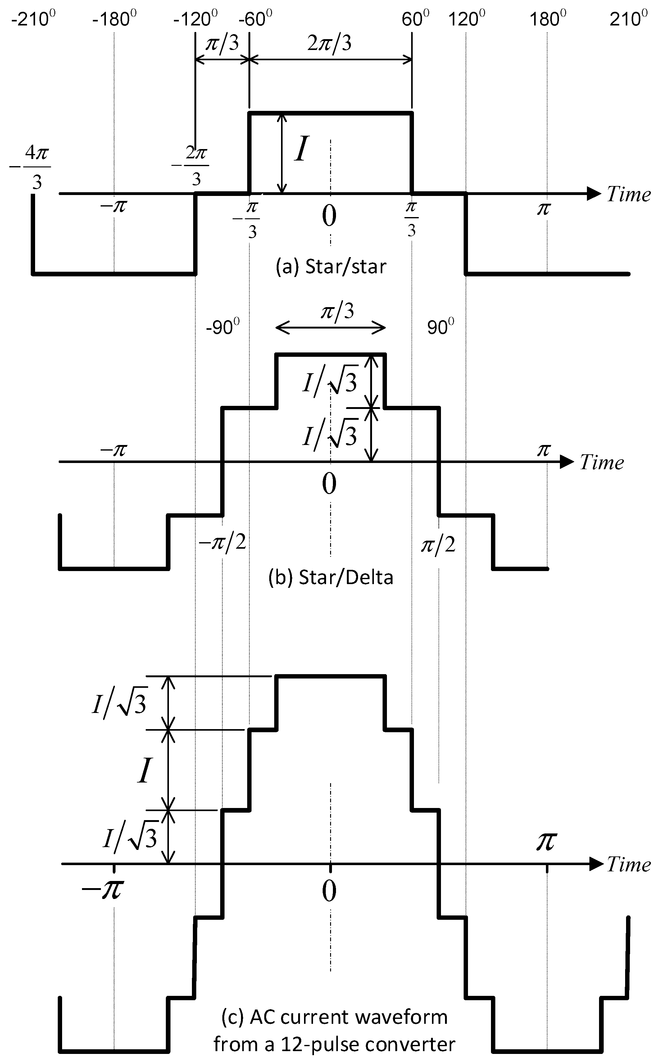
The characteristic AC current harmonics of the 6-pulse bridge of Figure 5 are h = 6 n ± 1 , n = 1 , 2 , 3 and their magnitude under ideal conditions is given by | I h | = | I 1 | / h where h is the harmonic order, | I h | the magnitude of the harmonic of order h , n an arbitrary integer and | I 1 | the magnitude of the fundamental component. As previously mentioned, the two 6-pulse bridges being connected together using different transformer winding configuration causes the following harmonic orders to cancel: h = 6 n ± 1 , n = 1 , 2 , 3 , 5 , 7 .The characteristic AC harmonic currents are therefore h = 12 n ± 1 , n = 1 , 2 , 3 , and on the DC side the DC harmonic voltages h = 12 n , n = 1 , 2 , 3 . Thus, harmonic filtering is needed both on the AC and DC side [44,45,46,47]. The AC current waveform of each converter–transformer and the combined waveform (Iac) is displayed in Figure 12.
The numbering of the thyristors in Figure 5 shows their firing order. Each thyristor conducts for 120 electrical degrees. The voltage across the thyristor becomes positive when the appropriate phase-to-phase voltage zero crossing occurs, and the firing angle is the delay between this point and when the thyristor receives a gate turn-on pulse. The thyristor only turns off when the current drops to zero (actual below its latching current) and this is achieved by firing another thyristor with a higher phase voltage. This is illustrated in Figure 13 for a commutation from thyristor 1 to 3 (thyristor 2 is already conducting). Commutation from 1 to 3 is only possible while phase Y is greater than phase R (between T1 and T2 in Figure 13). The extinction angle is the angle between when a thyristor stops conducting and the next zero-crossing when commutation can no longer occur. Hence γ = 180 ( α + μ ) . The maximum firing angle α is limited by the need to allow for the thyristor to re-establish its blocking ability and a margin to allow for voltage and current perturbations that naturally occur in the system. If the commutation from thyristor 1 to 3 has not been completed fully by T2 then Thyristor 1 will pick up the current again and hence commutation failure has occurred. The term Line-Commutated Converter (LCC) is often used for CSC as it indicates that the conversion process relies on the line voltage of the AC system to which the converter is connected in order to facilitate commutation from one thyristor to the next.
Only two quadrant operations (P versus Q) are possible, with the CSC always requiring reactive power regardless, whether rectifying or inverting. The reactive power required is approximately proportional to sin(α); therefore. an On-Load Tap Changer (OLTC) is normally provided on the converter transformer to minimize the firing angle when rectifying (or extinction angle for inversion) to minimize the reactive power required by the converter. The harmonic filters required to improve the AC current waveforms also perform the dual purpose of suppling some of the reactive power required by the converter [44].

3.3. Voltage Source Converters

Table 1 provides a comparison between VSC based and CSC based HVDC Systems [37]. Clearly when the AC system is weak, or passive and/or independent control of real and reactive power is required, VSC is preferable [37]. For the transmission of bulk power over long distances, the CSC based HVDC system has the advantage due to lower losses, although VSC based HVDC is improving with a decline in losses per converter over time: 3% (Gotland, 1997), 2.2% (Eagle Pass, 2000), 1.8% (MurrayLink, 2002), 1.4% (Estlink, 2006), 1% (Trans Bay, 2010, Superstation, 2014 & Dolwin 2, 2015). This is compared with a typical loss of 0.7% for CSC based HVDC [32].
Voltage Sourced Converter (VSC) topologies for HVDC power transmission either use two or three-level converters with Pulse Width Modulation (PWM), or a multilevel topology is used to achieve a better waveform with lower losses, or a hybrid [29,48,49]. The use of two or three-level converters requires series strings of semiconductor devices (IGBTs) to form one switch and switched together to achieve the required voltage and power ratings. Multilevel converters connect individual bridges or cells in series and avoid the need to simultaneously switch a large string of series IGBTs. This is because each cell is switched at a different time and a lower voltage is switched. This section will review the main topologies used for HVDC transmission and their characteristics.
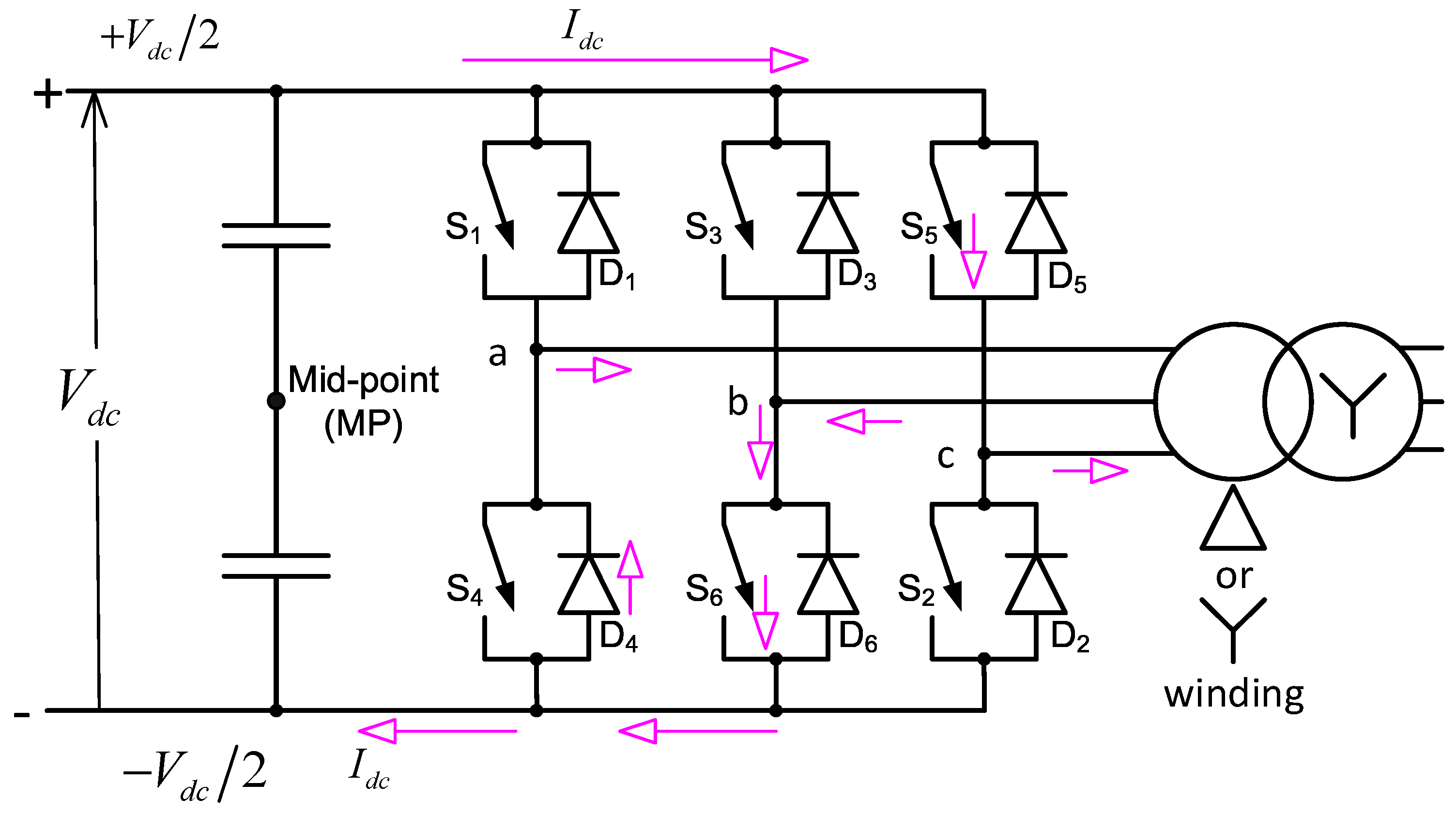
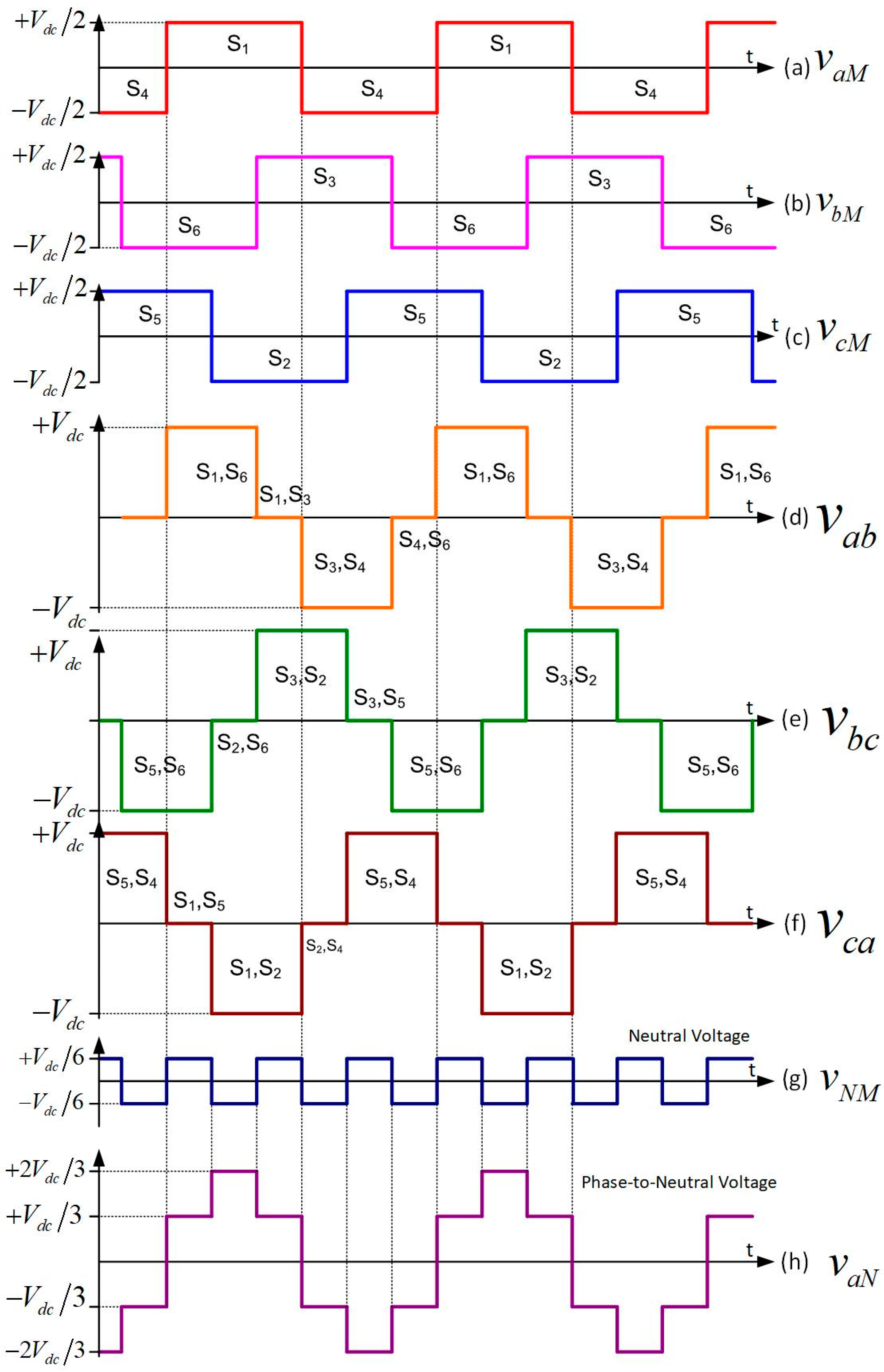
The basic 6-pulse VSC is displayed in Figure 14. The switches are power electronic devices, such as IGBTs, which conduct in one direction and the timing of the both turn-on and turn-off are controllable. An antiparallel diode allows conduction in the reverse direction. If fundamental frequency switching is performed, then the waveforms displayed in Figure 15 are obtained.
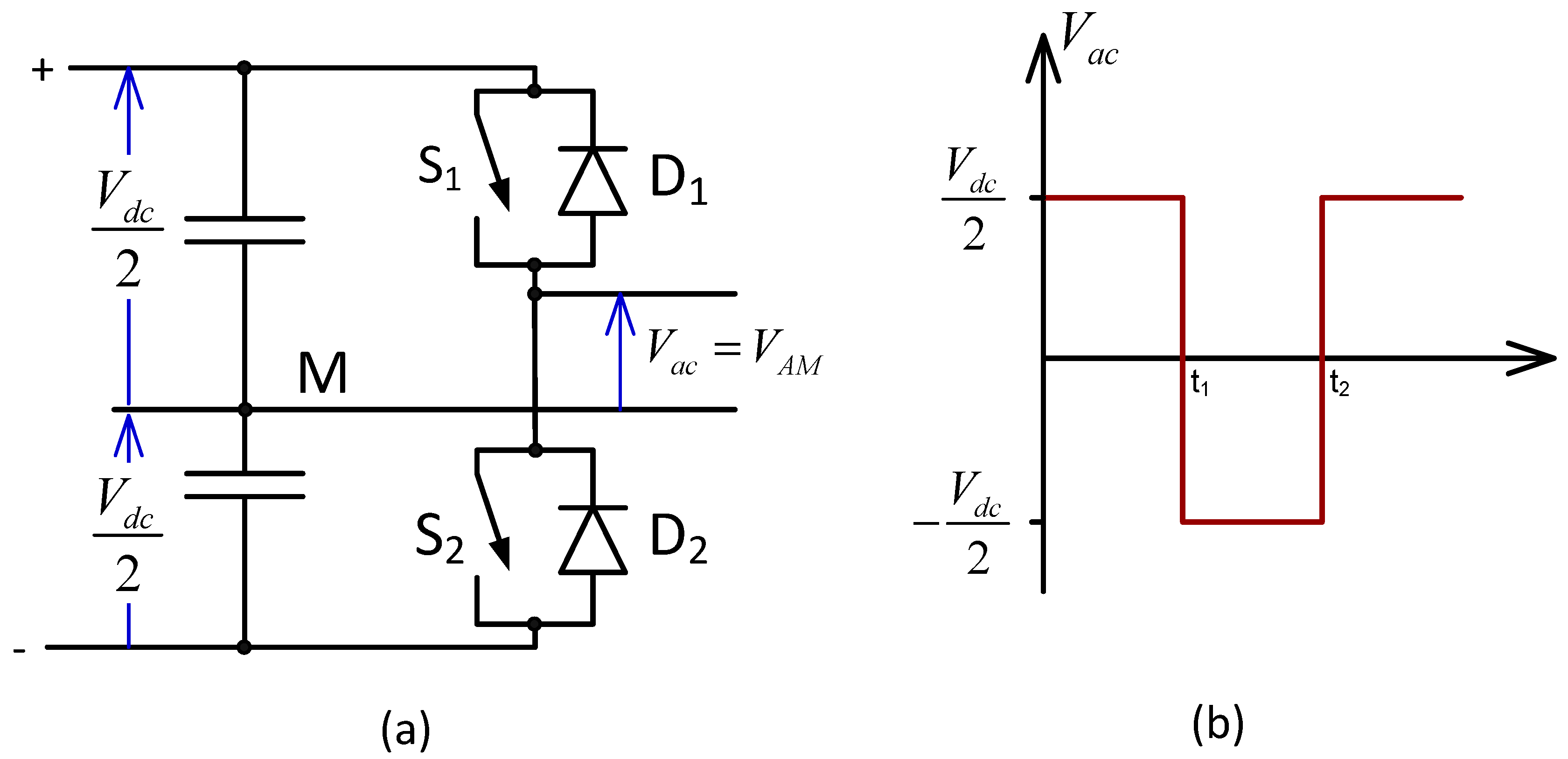
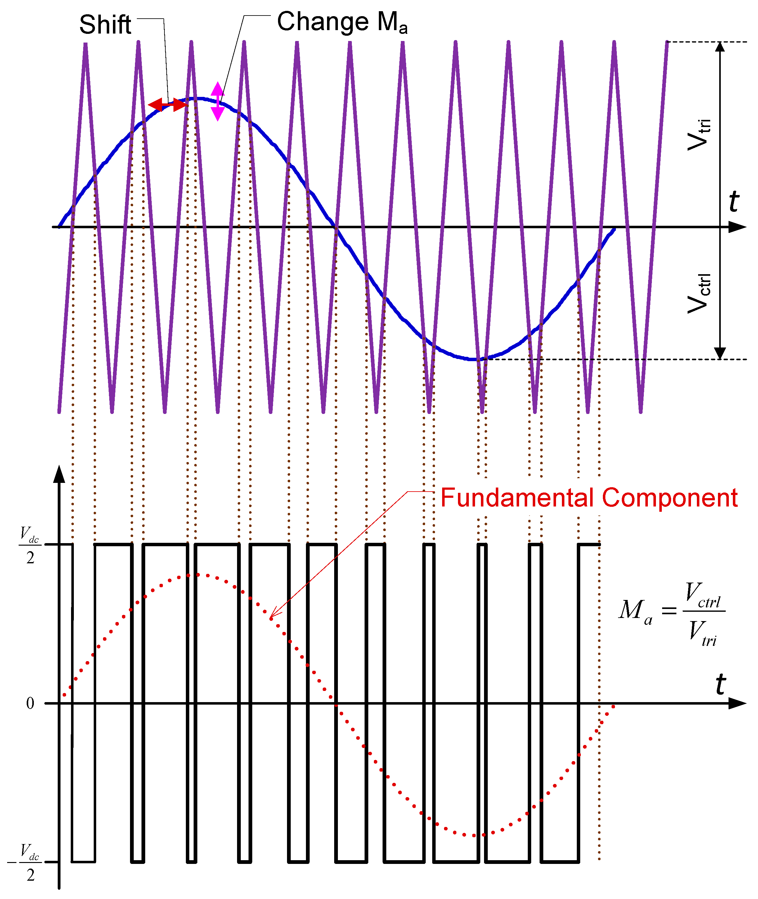
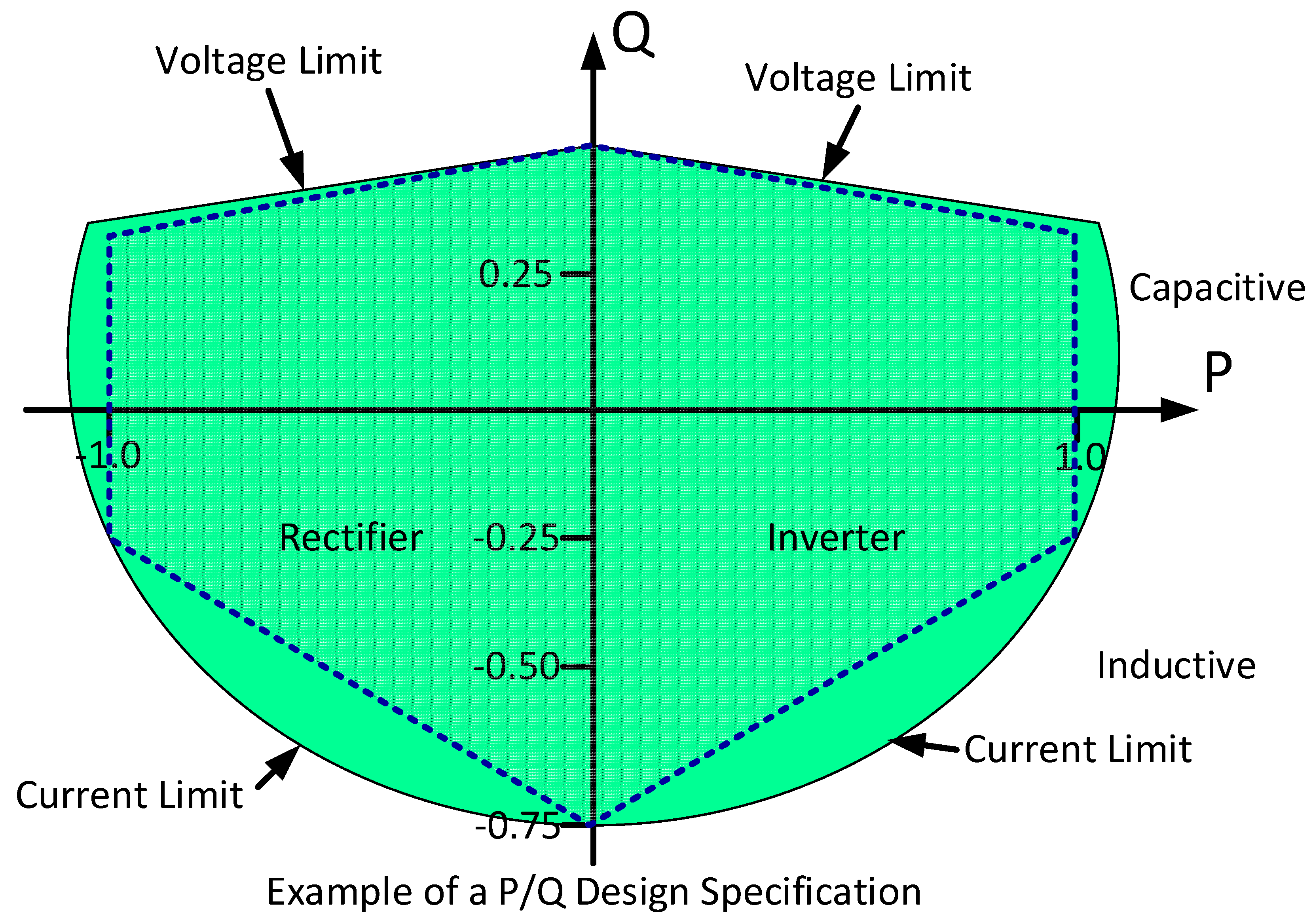
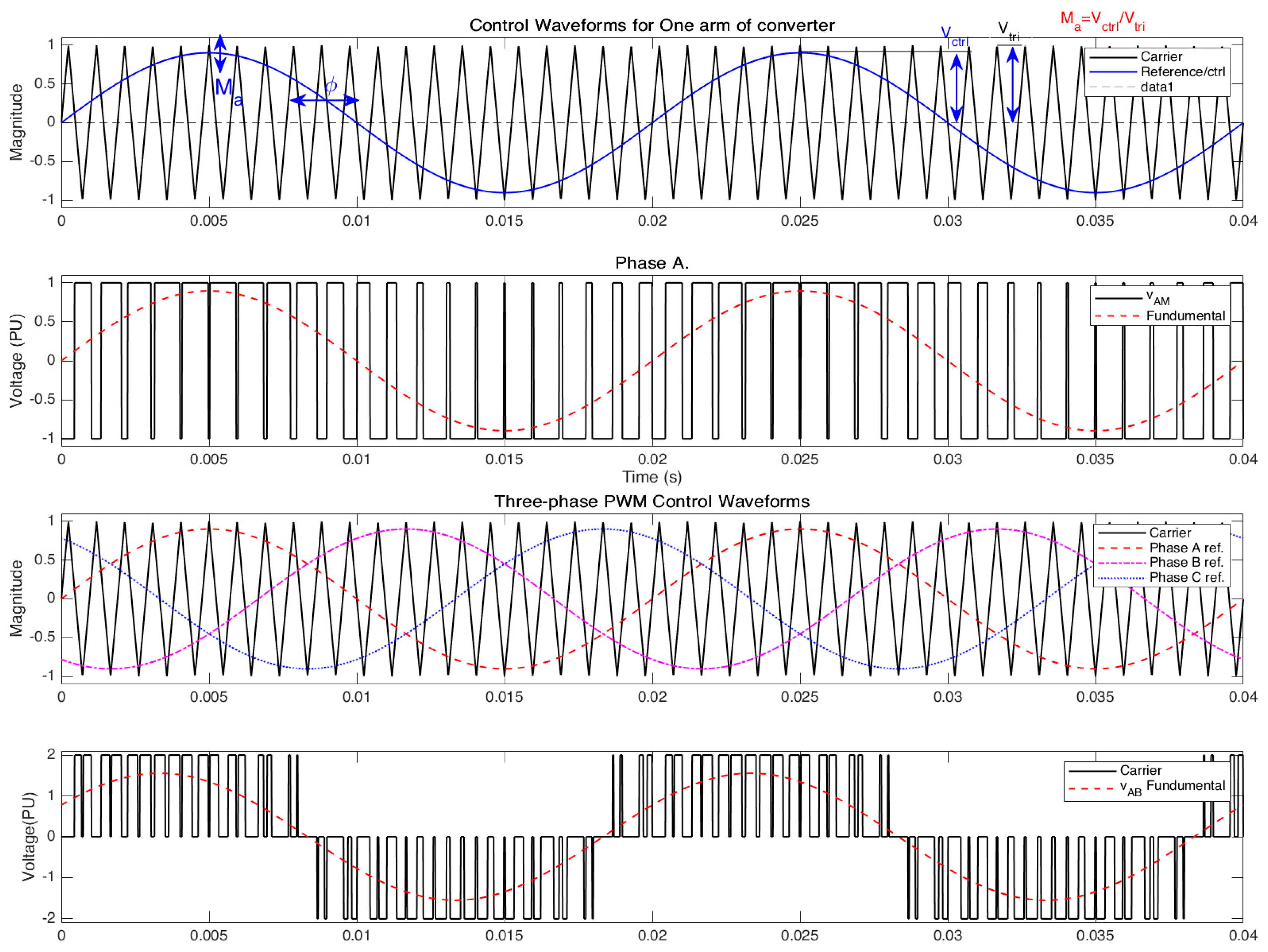
However, the real benefit of using devices with turn-off ability is the ability to use Pulse Width Modulation (PWM) techniques. To illustrate PWM consider one arm of a converter, shown in Figure 16. Depending on which devices are conducting, the output voltage (between voltage at the mid-point of the arm and DC mid-point of the capacitors) is either Vdc/2 or −Vdc/2. To improve the output voltage waveform the periods of Vdc/2 or −Vdc/2 would be modulated to approximate a sinewave. In sinusoidal PWM a triangular or carrier waveform is compared for a sinusoidal control/reference signal and the devices are switched when they cross as illustrated in Figure 17. Note there are two control variables, amplitude (by changing the modulation index, Ma) and phase angle (Φ) (by changing the control sinusoidal phase angle), and this allows independent control of the real and reactive power transferred to/from the AC system. In theory, the operational area in a P/Q diagram is circular; however, constraints on voltage and current modify this shape as illustrated in Figure 18, which shows the four quadrant operation of typical VSC in a PQ diagram [50]. In Figure 19 the single-phase PWM of Figure 17 is expanded to show three-phase PWM and the resulting phase-to-phase voltage waveform. PWM can also be used in multilevel converters, with a lower switching frequency required with more levels.
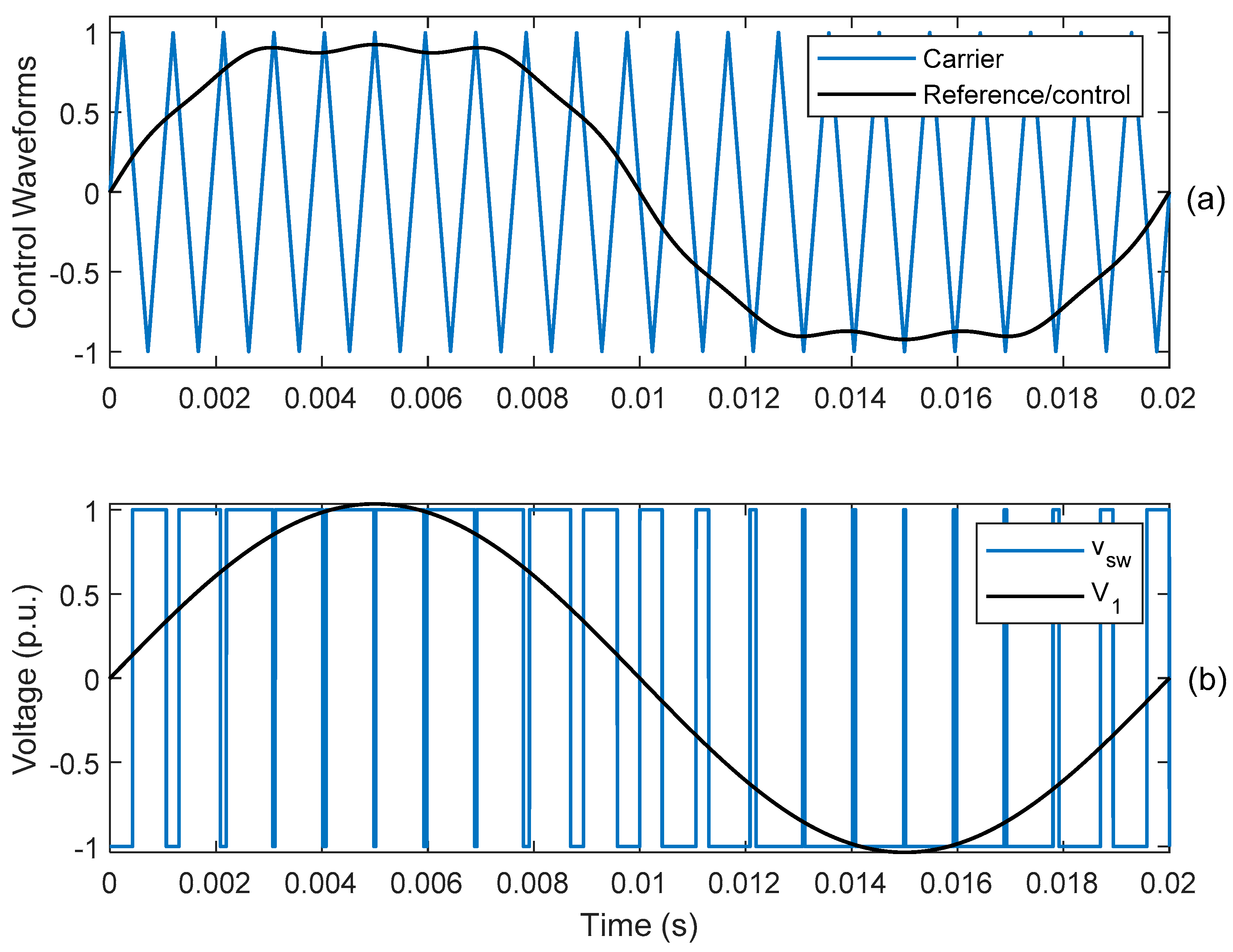
There is a trade-off between waveform distortion and losses as the higher the switching frequency the better the waveform but the higher the losses [51]. Various refinements to the standard sinewave PWM have been made to achieve different objectives. For example, rather than a pure sinewave control waveform, a zero third-harmonic component is added to the sinusoidal reference voltage, as illustrated in Figure 20. This reduces peak AC converter voltage in order that an approximately 15% increased AC-side fundamental-frequency voltage is available with the same DC voltage. For example, the Cross Sound Cable HVDC system uses this while MurrayLink does not [52]. Other optimized PWM schemes have been developed. For example, minor non-linearities in the valve switching can create low-order harmonics. To prevent their amplification, a special controller has been designed to act on the PWM pattern in order to minimize the low order (fifth and seventh) harmonic currents [53]. If the converter is near to generators there may be a need for sub-synchronous damping control [54]. AC and DC filtering is normally provided [55,56].
Another way to improve the waveforms is to use a multilevel topology. Some of the multilevel converters’ topologies are:
  • Neutral-point clamped circuit (also called a diode-clamped circuit)
  • Flying Capacitor
  • Cascaded H-bridge
  • Modular Multi-level Converter (MMC)
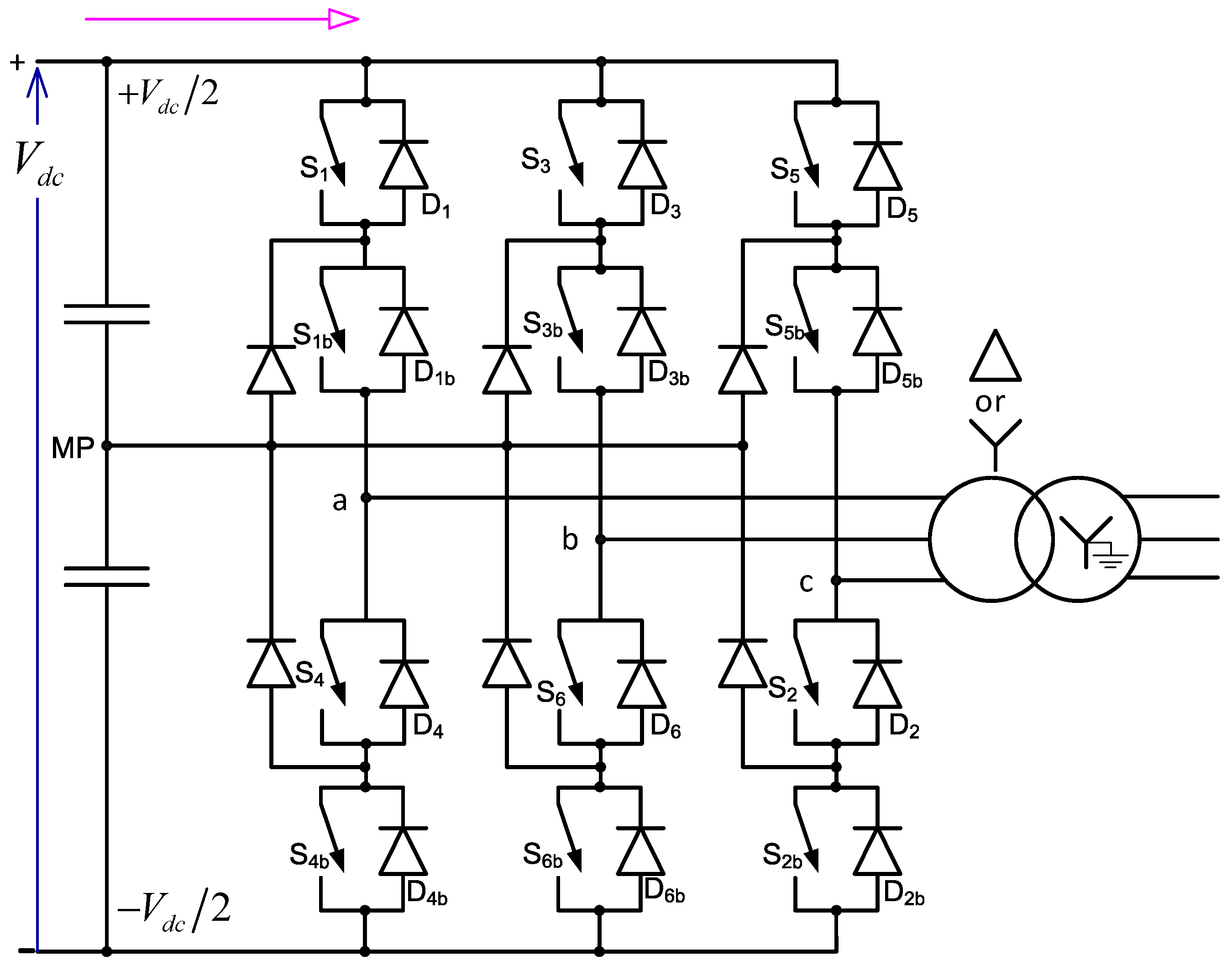
The cascade H-bridge and Flying capacitor converters each have features that discourage their use at high voltage and power levels. The 3-Level Neutral-Point Clamped (NPC) converter, shown in Figure 21, is a more suitable topology for such applications [57]. One of the issues is the asymmetric loss distribution in the semiconductor devices, and the Active Neutral-Point Clamped (A-NPC) converter overcomes this deficiency and has been used in HVDC schemes [58,59].
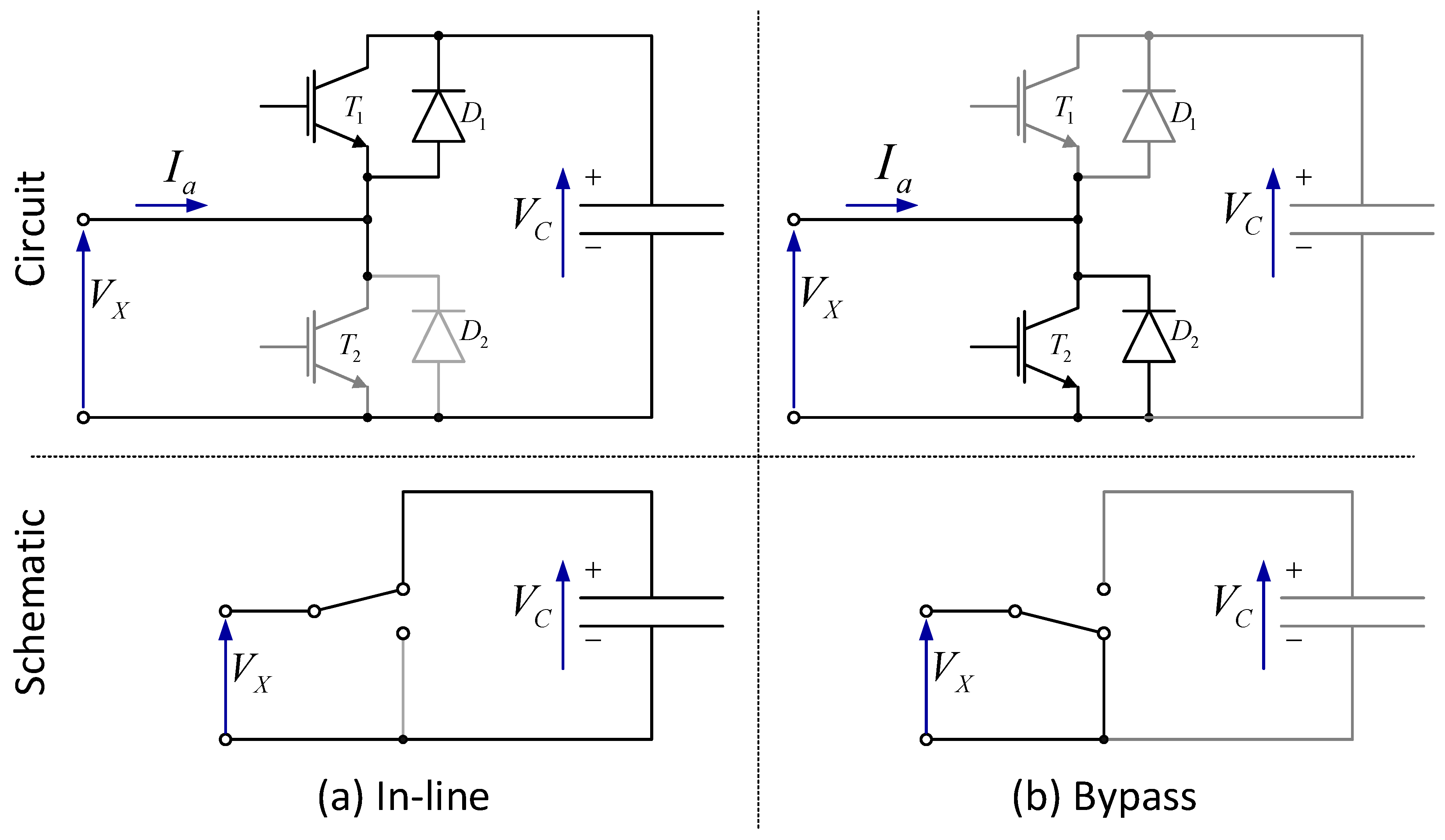
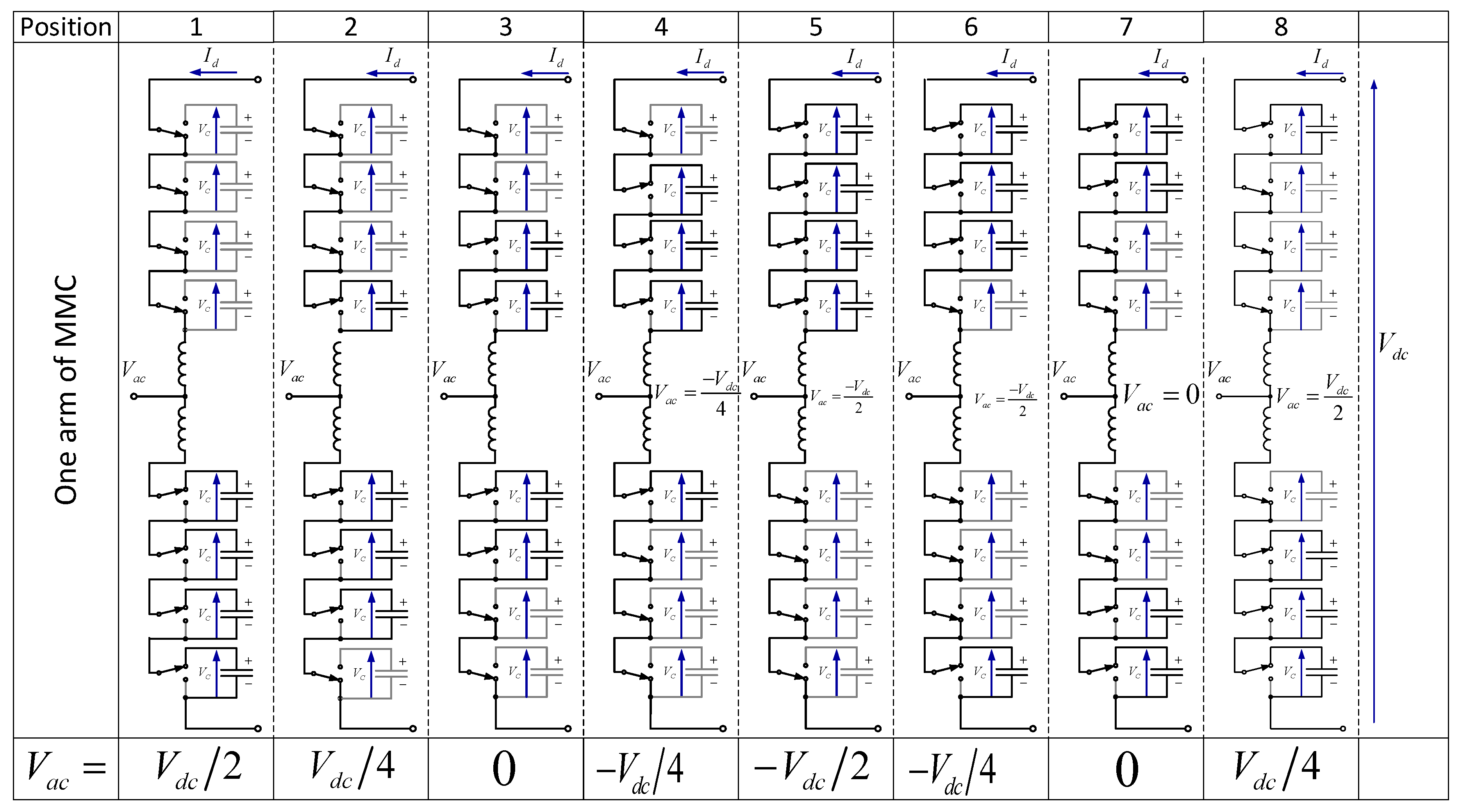
The Modular Multilevel Converter (MMC), displayed in Figure 22 and Figure 23, was introduced to the world in 2003 [60] and is now widely adopted due to its many advantages. Each arm of the MMC is made up of a number of submodules (SM) connected in series (Figure 22a). This arrangement allows the voltage rating of the switching devices in each submodule to be considerably less than the DC voltage. The submodule comprises of a half bridge, as shown in Figure 23, and has two states. The first connects the capacitor in series with the other submodules and the second bypasses it. With the appropriate switching pattern multi-levels can be produced. Some of these advantages are the modular design, making it scalable to different voltage and power levels, and multilevel waveform, expandable to any number of voltage steps, as well as low total harmonic distortion and low losses [61,62,63]. For these reasons it is very well suited for many applications such as HVDC. Note that:
  • Circulating currents are inherent in the MMC topology.
  • These currents cause variations in the capacitor voltages and increase converter losses.
  • Capacitor voltages variations increase with increase in load current and circulating currents.
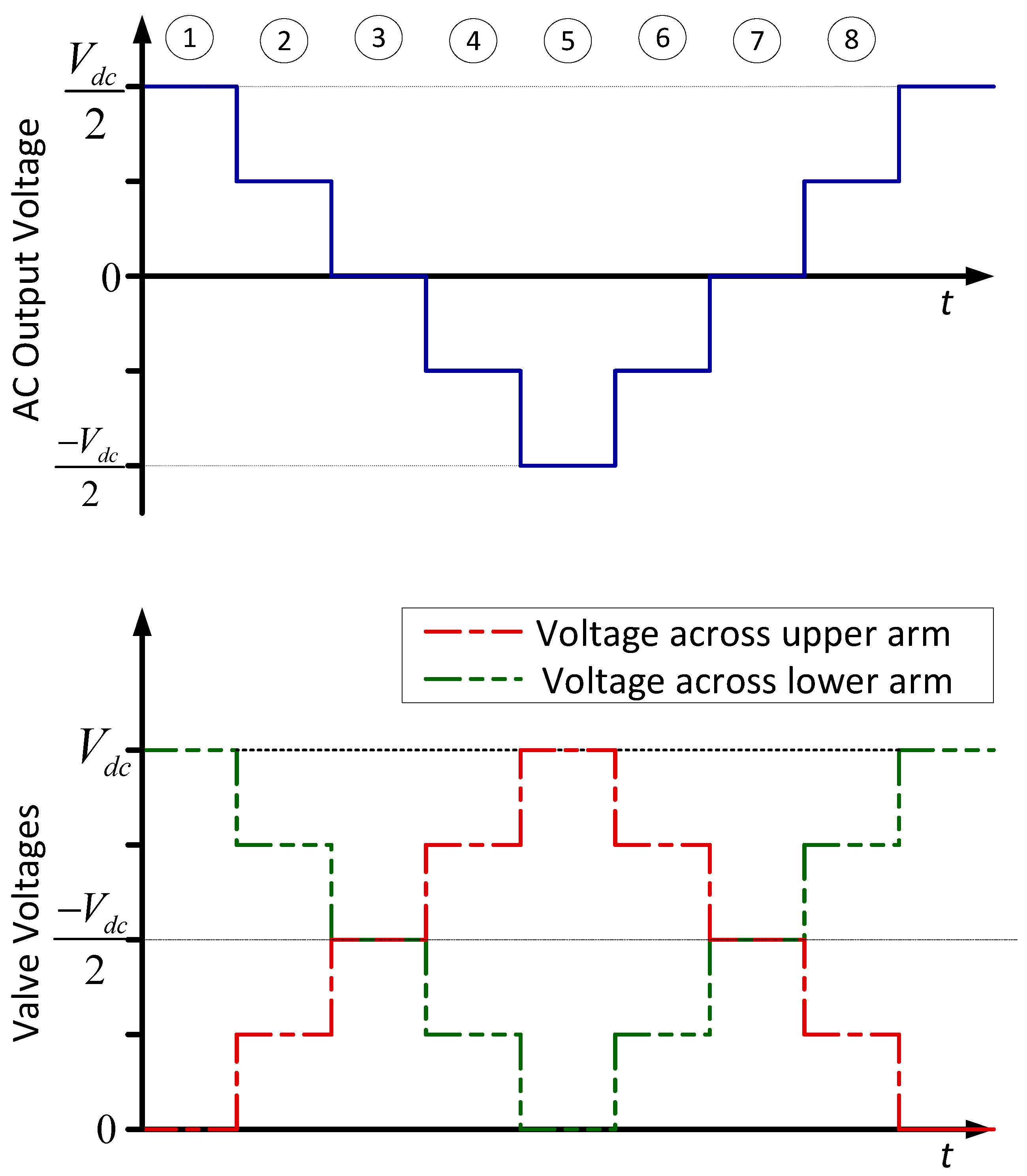
To aid understanding the of MMC’s operation, Figure 24 displays the output voltage from one phase of the MMC and Figure 25 the corresponding arm switching pattern for a given output voltage. The terminal voltage and current of an arm of the MMC converter is compared to that of a two-level PWM converter in Figure 26.
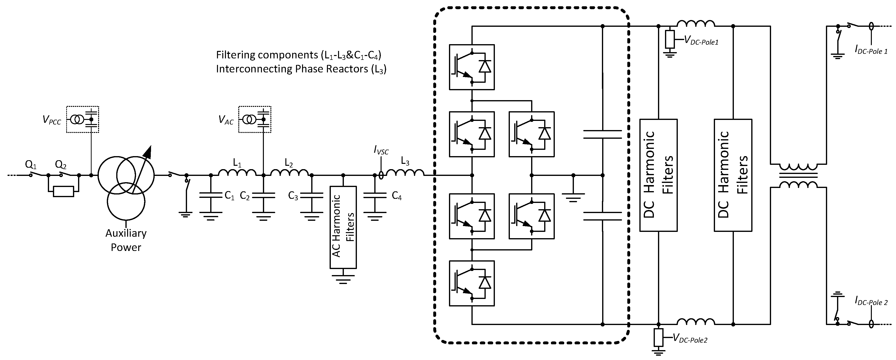
Figure 27 displays a generic converter station for a VSC based HVDC link. The details will vary and, depending on the local requirements and conditions, not all the components may be needed. In particular the filtering on the AC and DC side will be custom designed to meet the limits imposed, the converter’s emission characteristics (influenced by switching frequency and modulation technique), and the characteristics of the AC and DC systems it is connected to. These also influence the design of the converter controller. As an example, Figure 28 shows the converter station for the MurrayLink.

4. Historical Development

Although there were earlier experimental HVDC systems, the first commercial system was the 20 MW Gotland Island scheme commissioned in 1954. This LCC HVDC system used mercury-arc valves. In 1970 the first use of thyristors in a commercial HVDC link (Gotland Island) began. The last and largest mercury-arc based HVDC scheme was the Nelson River scheme commissioned in 1971. The delivery of bulk power over distance is best performed through overhead line or cables, and the cable technology made HVDC the best option. To overcome low system strength synchronous condensers were installed to aid commutation.
The improvements in IGBT technology allowed the VSC based HVDC schemes to be commissioned with the first being the 50 MW link to Gotland Island in 1999 [64]. This was quickly followed by the DirectLink Interconnector (Australia) in 2000 which interconnected two states (Queensland and New South Wales) [65]. Due to the limitations of the technology at the time, this consisted of three 60 MW VSC links in parallel. VSC HVDC was chosen due to its low environmental impact and the ability of converter stations to accurately control both real and reactive power. The Tjæreborg (Denmark) VSC based HVDC scheme was also commissioned in 2000. It was demonstration of using VSC HVDC for connecting a windfarm. Its rating was 7.2 MW. The MurrayLink connector between Berri (South Australia) and Red Cliffs (Victoria) was, at 180 km, the longest underground HVDC transmission system. It was commissioned in 2002 [52]. The Trans Bay Cable HVDC scheme completed in 2010 was the first system to use the MMC technology [66]. HVDC based on VSC was quickly adopted for supplying power to off-shore platforms and delivering power from off-shore windfarms. An HVDC link was commissioned to Troll A Off-shore platform (first and second lines) in 2005. BorWin1 was the first commercial HVDC scheme for importing power from an off-shore wind-farm (using two-level PWM) and was commissioned in 2009. There was a rapid development in wind-farms in this period and 2015 saw the commissioning of BorWin2 (MMC), HelWin1 (MMC), HelWin2, DolWin1 (using a Cascaded Two-Level Converter [67]). Besides the need for VSC based HVDC for cable systems, interconnections between countries or states are often at the extremities of their grids and hence electrically weak. The ability to independently control P and Q and feed a weak system does favour VSC systems. INELFE (Electric France–Spain Interconnection) uses an MMC topology. With the increase in variable renewable energy (primarily wind) the interconnection enables more optimal use of energy from renewable sources as well as improved security of the supply.
The first Multiterminal HVDC scheme was the three terminal Italy–Corsica–Sardinia scheme (known as SACOI). This started as a two-terminal LCC HVDC scheme between the Italian mainland and the island of Sardinia. A tapping from this was made in 1988 to allow up to 50 MW bidirectional power flow from the island of Corsica possible. Similarly, the second multiterminal HVDC scheme, Quebec–New England Transmission, which starts from Radisson Substation (Quebec) and runs to Sandy Pond in Massachusetts (USA). In 1992 a third converter station at Nicolet was commissioned to tap off power to supply the Montreal area. Both of these schemes use LCC HVDC. VSC based HVDC is generally better suited for multiterminal operation and is well suited for cable systems since the polarity of the DC voltage does not change. The Zhoushan Islands HVDC five-terminal voltage source converter project was commissioned in 2014 [68]. The four-terminal North-East Agra UHVDC system was commissioned in 2017.
A summary of the salient features of LCC based HVDC is given in Table 2 and those for VSC based HVDC schemes in Table 3.

5. Innovations in HVDC

5.1. Capacitor Commutated Converter

Figure 29 shows a schematic of an LCC HVDC system based on a capacitor commutated converter [70,71,72,73,74,75,76,77,78]. Putting a capacitor in series with the converter transformer lowers the commutating reactance and provides the following benefits:
  • Reduced reactive power demand hence reducing the amount of shunt compensation
  • Reduced area requirements
  • Simplified AC switchyard
  • Increased immunity to commutation failures
  • Increased stability at low SCR
  • Smaller overvoltages at load rejection
  • No AC side zero sequence currents
  • Improved control properties
  • Reduces shunt bank switching and transformer OLTC operations (reduces operation and maintenance costs)
The reasons for placing the capacitor on the converter side of the transformer rather than system side are that this reduces the transformer rating (reduced reactive flow through it) and removes the risk of ferroresonance or subsynchronous resonance (SSR). Furthermore, this lowers stress on the capacitor for an AC fault on the load side of the capacitor (transformer limits the fault current).
The back-to-back Garabi HVDC system uses capacitor commutated converters and connects Argentina (500 kV) to Brazil (525 kV) [79,80].

5.2. Continuously Tuned AC Filter

The AC harmonic filtering typically constitutes about 10% of the station losses as well as approximately 9% of the converter station cost [78]. They also have a considerable footprint. The continuously tuned AC filters are depicted in Figure 30. This passive filter uses a static reactor whose inductance can be controlled so the tuned frequency will follow the frequency and component variations [79]. These have been used in capacitor commutated converter based HVDC systems [80,81]. The greater cost of having an adjustable reactor is balanced by the improved performance.
A continuously tuned AC filter was first tested at the Lindome converter station of the Konti–Skan 2 HVDC Link and has since been installed on the Pacific Intertie HVDC system (1999) of the Swe-Pol Link, 600 MW (2000) and Garabi I and II [74].

5.3. Active DC Side Filters

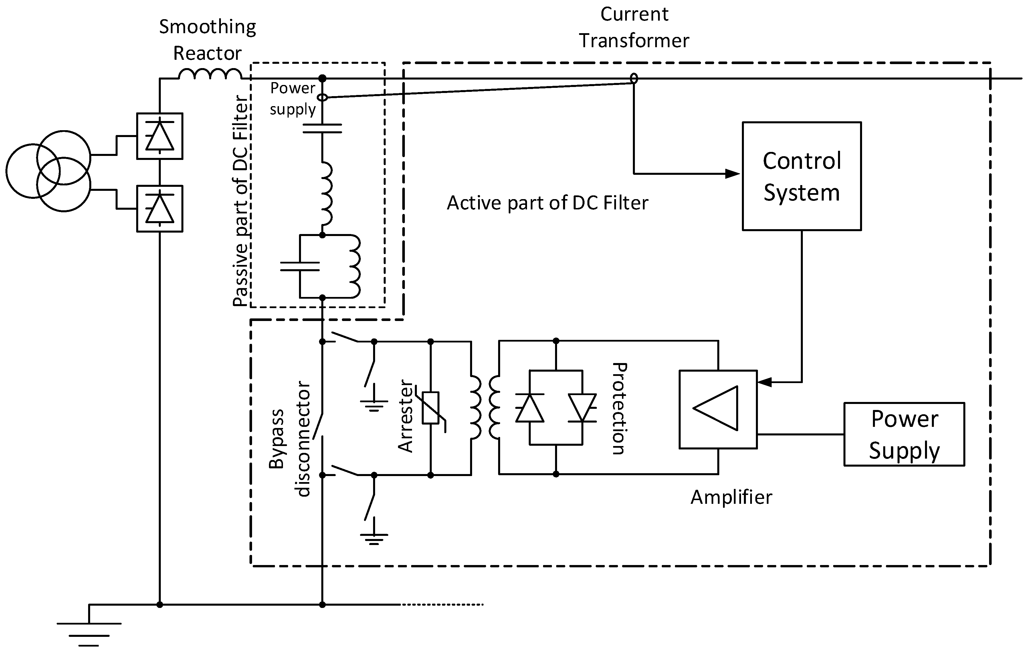
The main reason active DC filters are required is to meet stringent limits on DC side harmonics, to keep the disturbance levels in nearby telecommunication circuits within acceptable levels [78]. A schematic of an active DC filter is shown in Figure 31. The first commercial active DC filter was installed at the Tjele converter station in the Skagerrak 3 HVDC Intertie after first trialing the concept in 1991 on the Konti-Skan HVDC link [81]. The active DC filter is a passive doubled tuned 12/24 filter with an active part, located at the Kruseberg station (Sweden). The active filter was commissioned in 1993. This was followed by the Baltic cable HVDC in 1994 and Chandrapur-Padghe HVDC transmission project (1998) [82]. Both DC and AC side active filters are still being researched [83,84,85,86].

5.4. Reinjection Concept

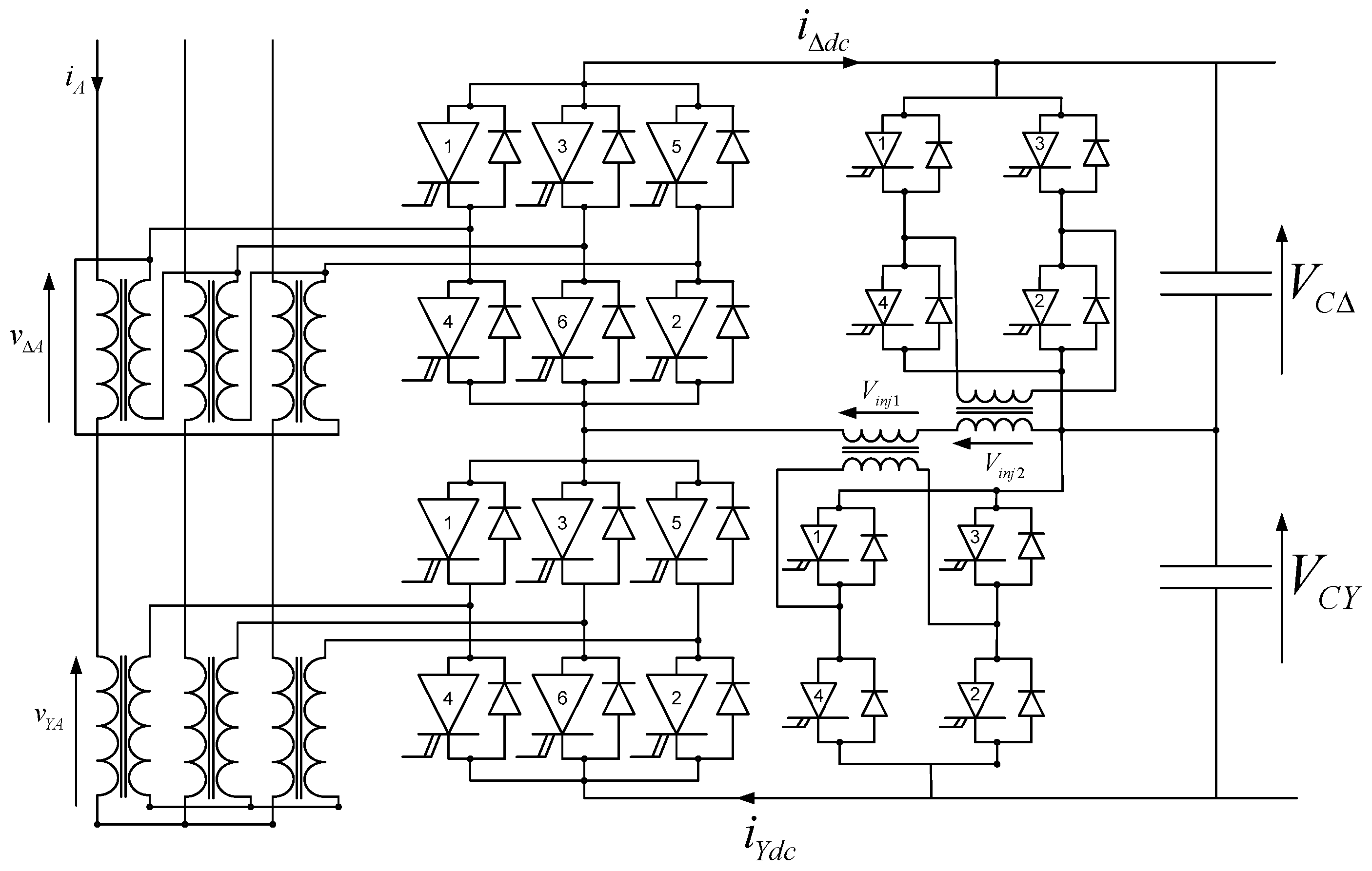
The concept of reinjection has developed significantly from the original ripple reinjection concept [87]. The concept is to increase the effective converter pulse number by reinjecting either DC current or DC voltage into the converter. Initially, this injection point was the converter transformer secondary; however, later the mid-point between the two bridges has been used. Both multi-level current and voltage reinjection converters have been developed using the reinjection principle. Besides dramatically improving the converter waveforms, features such as independent P and Q control in current source converters have been achieved while maintaining the ability to control DC fault currents. The main impediment is the complexity and cost. An auxiliary reinjection bridge and reinjection transformer are required. In the current reinjection converter, although the main converter bridges still use thyristors, the reinjection bridge must use power electronic switches with turn-off capability. As an illustration, Figure 32 shows a multi-level voltage reinjection converter [22,23,88,89].

5.5. DC Faults

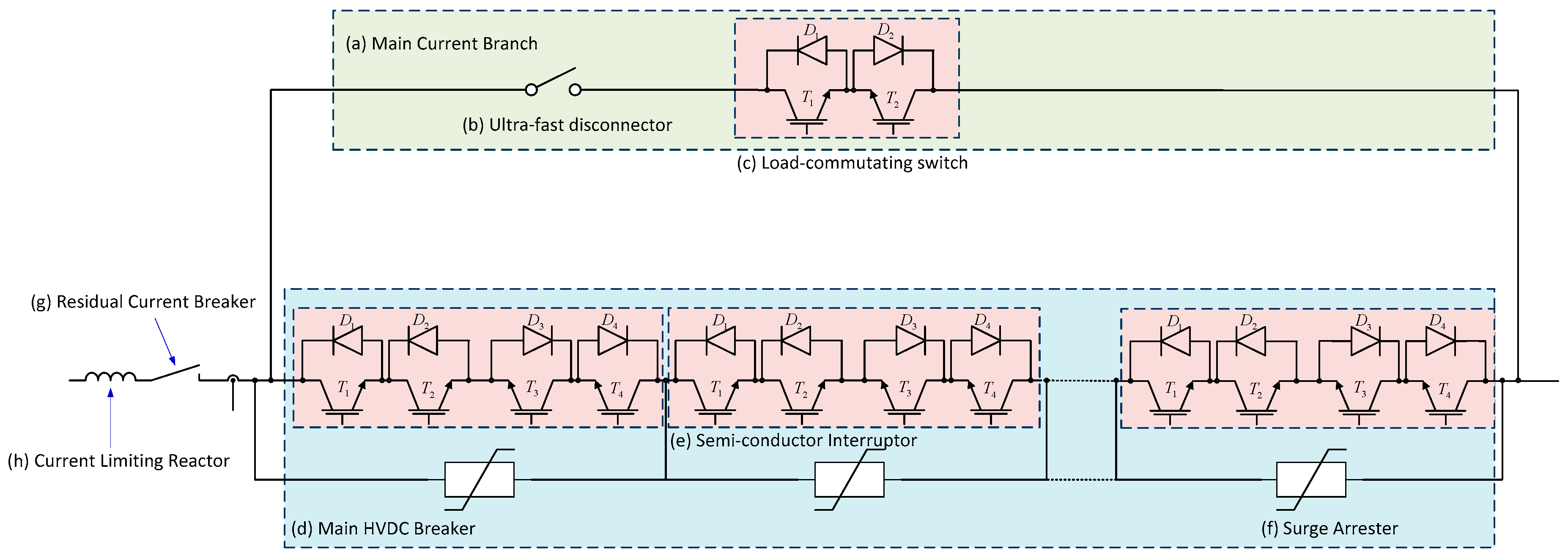
When a fault occurs on the DC system, CSC converters have the ability to de-energise the DC system while VSC converters continue to feed the fault as the antiparallel diodes act as an uncontrolled rectifier. Most VSC based HVDC schemes rely on the AC side protection detecting and de-energising the system. Various techniques have been proposed or used for allowing VSC based systems to cope better with DC side faults. Adding a full converter in the arms of the MMC converter, adding parallel bypass thyristors to each semi-module in an MMC converter and the development of DC circuit breakers (see Figure 33) have all been reported in the literature. The need for DC breakers is heightened with the development of multiterminal HVDC systems. Without DC breakers the multiterminal HVDC grid is what some call regional, in that the system constitutes one protection zone for a DC earth fault. Such a fault will cause temporary loss of the whole HVDC system. An inter-regional HVDC system needs effective and affordable DC breakers so that the system has a number of protection zones and an earth fault will only affect part of the system [90]. This is an active area of research with numerous hybrid and solid-state breaker topologies researched [32,90,91,92,93,94,95].

6. Discussion

The trend of conveying higher power levels over longer distances will continue, resulting in a demand for transmission at higher voltage levels for both LCC and VSC HVDC systems [96,97,98,99,100,101].
Further development of simulation tools is required for a converter rich system of the future, due to the possible complex interactions over different time-scales [102]. Electromagnetic Transient simulation tools are presently available, but their detail and complexity make them unsuitable for large system studies. They are computationally expensive, as the frequency switching of devices restricts the time-step that can be used [103,104]. Because of the various system time constants, co-simulation techniques for mixed time-frame simulation are gaining popularity [105]. A recent publication [106] provides seven HVDC system models that can cover most HVDC grid applications. This provides a starting point for project feasibility assessments and specifications and enables researchers to customise and benchmark their studies. Moreover, the overview gives a useful review of previous publications and technology. Due to the cost and footprint of filtering equipment, and inherent losses, the trend towards low distortion current waveforms will continue. Often these techniques produce distortion at higher frequencies which are challenging to accurately model.
Hardware-in-the-loop (HIL) testing where actual hardware (control and protection equipment) are interfaced with a real-time digital simulator in a closed-loop arrangement has become a very important facility in identifying problems and mitigating them before the equipment is transported to the site and commissioned.
Power electronic converters are modulators (i.e., they couple the AC side and DC side frequencies) with various sensitivities, based on their control systems and topology. The terms “cross-modulation” and “harmonic interaction” have been used to refer to these phenomena and both CSC and VSC converters act as modulators, transferring and translating the distorting frequencies on one side to the other [105]. The converter can be viewed as a three-port device as the positive and negative sequences on the AC system couple to different frequencies on the DC side. This manifests itself in various ways, such as in composite resonances or core-saturation [107]. For example, in LCC HVDC schemes when the AC and DC lines share a common right-of-way the induced fundamental in the DC line can give rise to core-saturation in the converter transformer. Although HVDC converters and their controls can create undesirable interactions, which must be avoided, they also have the ability to dampen oscillations inherent in the AC system by the use of supplementary inputs, which is a fruitful avenue of research at present [108].
As obtaining right-of-way becomes more difficult there will be increasing pressure to use existing right-of-ways. This may mean either sharing it with AC circuits or converting the existing AC lines to DC and more research is needed on the best way to do this.
The role of telecommunication systems in HVDC systems also needs evaluating carefully. Initially the HVDC converters were controlled based on local variables (DC voltage, DC current, DC Power) and the telecommunication system carried orders for changing the settings. A disturbance in an AC system would naturally result in a new stable operating point without the need for intervention by a telecommunication system. However, if a reliable communication system is available, then improvements in coordination, control and protection are possible and need researching, as do failure modes in the case of a failure of the telecommunication system.
Many HVDC systems undergo partial refurbishments and the technical difficulties are found in interfacing the new equipment and system with the parts of the existing system. The technological developments in equipment can make this challenging. However, new technologies also create new opportunities, such as DC current measurements through direct current Current Transformers (CTs) (Zero Flux and Optical CTs), which are faster, more robust and accurate digital control systems, to name but a few.

6.1. VSC HVDC Systems

The forming of multiterminal VSC-based HVDC to form HVDC Grids is a very active area of research due to the desirability of such systems. This is multifaceted as it involves control systems and protection of such systems. Under normal operation how are the converters to be coordinated and what role do communication systems have in this [47,109,110]? What modulation technique is used and how are the capacitors in multi-level systems balanced? For example, in the MMC the voltage balance across the sub-module capacitors must be maintained and the circulating current limited, and this has stimulated research into modulation methods for the MMC. In the MMC a fast acting thyristor is placed across the sub-module/cell and triggered to protect the cell diode when a DC fault occurs. Clearance occurs when the AC circuit breaker operates. The diode in the MMC’s semi-module (or parallel thyristor) acts as an uncontrolled rectifier when a DC fault occurs and using two antiparallel diodes has been proposed to stop the uncontrolled rectification [111]. Hybrid multi-level converter topologies utilising director switches have been proposed [37,112]. Rather than using half-bridges as the sub-module, another option is to use a full-bridge and this is the basis for the alternate arm version of the hybrid MMC [28,113,114,115]. Applying full-bridge cells in series with the “Director” valves enables the multilevel cells to provide a voltage that opposes and limits the flow of current into a DC network short circuit [37]. This enables the converter to remain connected and ready to continue power transmission once the fault is removed. However, this increases the converter losses and the number of semi-conductor devices. More work is required in developing VSC converters that are tolerant to DC faults and low loss. Moreover, a fast and cost-effective DC circuit breaker is needed to limit the impact of DC side faults, particularly in multiterminal systems. The identification and mitigation of DC side faults still needs more research especially for multiterminal systems where isolating only the faulted line without causing power interruption to the whole network is required. Some have recommended that the primary protection should be based on local quantities and backup protection pilot wire. In an LCC HVDC system the DC smoothing reactor limits the rise of the fault current and the control action of the thyristor can extinguish the arc. In a VSC system on fault inception the charge in the DC capacitances will discharge to the fault point rapidly and the DC voltage drops quickly.
VSC converters are susceptible to unbalance in the AC system they are attached to. The negative sequence component in the AC system causes a second harmonic component on the DC side, which in turn results in unbalanced waveforms in the AC system the other VSC is connected to [116]. The transmitted power has an oscillatory component and a double-frequency reactive power ripple appears on the AC side.
With the development of renewable generation in remote areas the short-circuit-ratio (SCR) where VSC converters are required to operate is dropping and there are control issues in such scenarios. Unwanted control interactions can occur, either with other VSC converters, or generators that are electrically close or simply with the weak AC system. Grid connected converters use a Phase-Lock-Loop (PLL) for synchronizing to the grid and its performance when the AC is weak, or a disturbance occurs, can negatively impact the system’s performance. Grid synchronization and robust control becomes an issue, particularly in the face of a weak AC system and multiple converters. Overcoming the weaknesses in the PLL is of great importance for the stability of the system. As more converter based generation is integrated into the system and displaces conventional synchronous machine based generation, the rotational inertia drops. The frequency regulation becomes more difficult and in the event of a disturbance the system is more likely to be unstable. Another active strand of research is on methods of enabling power electronic converters to provide what is termed synthetic or virtual inertia. That is, provide real power to stabilise the AC system immediately after a disturbance as a synchronous machine does by converting some of its kinetic energy to electrical energy as the frequency drops, or vice versa. Another strand is to design a grid-tie converter without the traditional PLL for connection to weak AC systems [117,118,119].
Unlike the LCC, VSC does not suffer from commutation failure when an AC system fault occurs; however, the challenge is for the control system to limit any transient overvoltage or overcurrent [51].
Improving the tolerance of HVDC systems to AC and DC faults is a challenging area to research but it is needed to ensure reliable power transmission. VSC-based HVDC systems have a particular challenge with DC faults. Research into topologies, control techniques, materials and devices are all needed. However, research into converter control systems has the potential to solve many of the problems that have been experienced to date. The coordination of multiterminal HVDC systems, improved steady-state performance in weak AC systems and better dynamic performance and elimination of control interactions are still areas requiring further research.

6.2. CSC-Based HVDC Systems

CSC HVDC schemes, being line-commutated, are even more dependent on the AC system for commutation to occur and often synchronous condensers have been placed at the inverter end if the SCR is too small to ensure commutation failure does not occur [120]. As with VSC systems, unwanted control interactions can occur with other electrically close equipment [54]. It is usually convenient to subdivide instabilities into several types, distinguished by their frequency. Ref. [99] gives a good overview of the control interactions and instabilities that can occur in LCC HVDC systems, their mechanism and a few examples of where they have occurred. These instabilities can be categorised by their frequency as follows: (a) Super-synchronous instability (often loosely referred to as “harmonic instability” despite not being an integer multiple of the fundamental), (b) Core-saturation instability, (c) Subsynchronous instability (typically 5–40 Hz) and (d) Power control instability. The response time of the DC controls is short compared to other time constants of the network.
The controllability of HVDC converters also opens the opportunity to provide supplementation controls to help dampen AC system instabilities. When considering an LCC HVDC system, typical considerations are:
  • Load rejection overvoltages
  • Temporary overvoltage after recovering from an AC system fault
  • Voltage change on reactive switching
  • AC network frequency and stabilisation/modulation control
  • Possible subsynchronous torsional interactions with nearby turbine-generators.
These issues still exist and must be considered when planning an LCC HVDC system [119]. Where previously an AC system had only one infeed, an AC system may now have multiple HVDC systems interconnecting it and the interaction between converters is of growing importance [54]. Moreover, the interaction between AC and DC systems is becoming more significant as more HVDC systems are deployed.
The control systems for a DC transmission system must be stable with adequate stability margins in the whole range of operation. The role of communication systems in HVDC is changing. Previously with LCC, HVDC communication systems were not relied upon. This resulted in a Hierarchical control system (Valve firing (1 ms), Pole (10 to 500 ms) & Master control (up to 10 s)) where the lower levels relied only on terminal conditions and were designed to transition to a new stable operating point if a disturbance occurred without the need for information from the other end. A high level signal would give the coordinating command for steady-state operation. The control speed of a converter is very fast compared to the AC system time constants and in some cases may have to be limited based on the capacity of the network to support variations in the real and reactive power of the converters. The reliability of modern communication systems is such that many are looking at placing higher reliance upon it for both control and protection roles for both LLC and VSC based HVDC systems. The question is the best way to utilize the communication system while still maintaining a robustness to outages.

6.3. Hybrid HVDC Systems

Recently the application of both LCC and VSC technologies within the same HVDC system has emerged, to allow the advantages of both technologies to be exploited [121,122,123,124,125,126,127,128]. The hybrid LCC/VSC was first used in the Skaggerak HVDC system between Denmark and Norway. Skaggerak 3 uses LCCs while Skaggerak 4 used VSCs and these were configured to form a hybrid bipole HVDC system [122,123]. The first hybrid back-to-back HVDC system was the Luxi HVDC system commissioned in 2016 [123,124]. The first hybrid multiterminal scheme, the Kun-Liu-Long HVDC system, uses LCC for the rectifier side and two MMC based inverter terminals [124]. Using LCCs as rectifiers and VSCs as inverters takes advantage of the LCC’s higher power rating, lower power losses, lower manufacturing cost and self-extinguishing capability for DC line faults. Moreover, it also eliminates the risk of commutation failure by using the VSCs as the inverters. There are however applications which may necessitate VSCs to act as the rectifier, such as offshore windfarms, where the strict limitations on space on the offshore converter platform means the more a compact MMC is required. This is partly due to the absence of bulky AC filters. Offshore platforms can also benefit from the black-start capability and independent real and reactive power control.

7. Conclusions

The technological development in solid-state devices, converter topologies and control techniques will continue to improve the attractiveness of DC transmission systems. Regardless of whether AC or DC there will always be a need to transform the voltage to the optimum level for transmission and distribution, based on the length and power transmitted. The cost, efficiency and reliability of modern transformers means the grid of the future is most likely to be a hybrid AC/DC system with more DC being deployed and embedded in AC systems. There is already research on DC transmission, not only at the HV and UHV, levels but Medium Voltage (MV) and Low Voltage (LV) levels [129]. This paper has discussed the present state of HVDC technology, deficiencies and where further research and development is required. It is clear that DC transmission will play an important and increasing role in the grid of the future and control systems design will be more critical to ensure undesirable interactions do not occur, particularly when the AC system is weak.

Author Contributions

Most of the investigation was performed by N.R.W.; both N.R.W. and J.D.W. were involved with the writing and reviewing and editing the manuscript; All authors have read and agreed to the published version of the manuscript.

Funding

This research received no external funding.

Conflicts of Interest

The authors declare no conflict of interest.

Correction Statement

This article has been republished with a minor correction to resolve spelling and grammatical errors. This change does not affect the scientific content of the article.

References

  1. CIGRE WG B6.31. Medium Voltage Direct Current (MVDC) Feasibility Study. Technical Brochure 793. 2020. Available online: https://e-cigre.org/ (accessed on 5 March 2020).
  2. CIGRE WG B4.55. HVDC Connection of offshore Wind Power Plants. Technical Brochure 619. May 2015. Available online: https://e-cigre.org/ (accessed on 13 July 2015).
  3. Ryndzionek, R.; Sienkiewicz, L. Evolution of the HVDC Link Connecting Offshore Wind Farms to Onshore Power Systems. Energies 2020, 13, 1914. [Google Scholar] [CrossRef]
  4. Korompili, A.; Wu, Q.; Zhao, H. Review of VSC HVDC connection for offshore wind power integration. Renew. Sustain. Energy Rev. 2016, 59, 1405–1414. [Google Scholar] [CrossRef]
  5. Jiang-Häfner, Y.; Lundberg, P. VSC HVDC Transmission Supporting Variable Electricity Generation, CIGRE Session, Paris, 2016, Paper C5-204. Available online: https://e-cigre.org/ (accessed on 17 April 2020).
  6. Gupta, K.K.; Bhatnagar, P. Multilevel Inverters: Conventional and Emerging Topologies and Their Control; Academic Press: London, UK, 2018. [Google Scholar]
  7. Mohan, N.; Underland, T.M.; Robbins, W.P. Power Electronics: Converters, Applications, and Design, 3rd ed.; John Wiley & Sons: New York, NY, USA, 2003. [Google Scholar]
  8. Rashid, M.H. (Ed.) Power Electronics Handbook, 3rd ed.; Butterworth-Heinemann: Burlington, MA, USA, 2011. [Google Scholar]
  9. Holmes, D.G.; Lipo, T.A. Pulse Width Modulation for Power Converter: Principles and Practice; IEEE Press: Piscataway, NJ, USA, 2003. [Google Scholar]
  10. Wu, B. High-Power Converters and AC Drives; IEEE Press: Piscataway, NJ, USA, 2006. [Google Scholar]
  11. Shepherd, W.; Zhang, L. Power Converter Circuits; Marcel Dekker: New York, NY, USA, 2004. [Google Scholar]
  12. Sharkh, S.M.; Abusara, M.A.; Hussain, B. Power Electronic Converters for Microgrids; John Wiley & Sons: Singapore, 2014. [Google Scholar]
  13. General Electric Canada Inc. Power Converter Handbook: Theory, Design, Application; UYK Technologies: Bailieboro, ON, Canada, 2005. [Google Scholar]
  14. Adamson, C.; Hingorani, N.G. High Voltage Direct Current Power Transmission; Garraway: London, UK, 1960. [Google Scholar]
  15. Kimbark, E.K. Direct Current Transmission: Volume 1; John Wiley & Sons: New York, NY, USA, 1971. [Google Scholar]
  16. Uhlmann, E. Power Transmission by Direct Current; Springer: Berlin/Heidelberg, Germany, 1975. [Google Scholar]
  17. Arrillaga, J. High Voltage Direct Current Transmission, 2nd ed.; IEEE: London, UK, 1998. [Google Scholar]
  18. Padiyar, K.R. HVDC Power Transmission Systems: Technology and System Interactions; John Wiley & Sons: New Delhi, India, 1990. [Google Scholar]
  19. Yazdani, A.; Iravani, R. Voltage-Sourced Converters in Power Systems: Modeling, Control and Applications; John Wiley & Sons: Hoboken, NJ, USA, 2010. [Google Scholar]
  20. Jovcic, D.; Ahmed, K. High Voltage Direct Current Transmission: Converters, Systems and DC Grids; John Wiley & Sons: Chichester, UK, 2015. [Google Scholar]
  21. Kim, C.-K.; Sood, V.K.; Jang, G.-S.; Lim, S.-J.; Lee, S.-J. HVDC Transmission: Power Conversion Applications in Power Systems; John Wiley & Sons: Singapore, 2009. [Google Scholar]
  22. Arrillaga, J.; Liu, Y.H.; Watson, N.R. Flexible Power Transmission: The HVDC; John Wiley & Sons: Chichester, UK, 2007. [Google Scholar]
  23. Arrillaga, J.; Liu, Y.H.; Watson, N.R.; Murray, N.J. Self-Commutating Converters for High Power Applications; John Wiley & Sons: Chichester, UK, 2009. [Google Scholar]
  24. Chaudhuri, N.R.; Chaudhuri, B.; Majumder, R.; Yazdani, A. Multi-terminal Direct-Current Grids: Modeling, Analysis, and Control; IEEE Press: Piscataway, NJ, USA, 2014. [Google Scholar]
  25. Sharifabadi, K.; Harnefors, L.; Nee, H.-P. Design, Control, and Application of Modular Multilevel Converters for HVDC Transmission Systems; John Wiley & Sons: Hoboken, NJ, USA, 2016. [Google Scholar]
  26. Acha, E.; Roncero-Sanchez, P.; de la Villa, A.; Castro, L.M.; Kazemtabrizi, B. VSC-FACTS-HVDC: Analysis, Modelling and Simulation in Power Grids; John Wiley & Sons: Chichester, UK, 2019. [Google Scholar]
  27. ABB. ABB Review: Special Report 60 Years of HVDC. July 2014. Available online: https://new.abb.com/about/technology/abb-review (accessed on 15 July 2020).
  28. Kharade, J.M.; Savagave, N.G. A Review of HVDC Converter Topologies. Int. J. Innov. Res. Sci. Eng. Technol. 2017, 6, 1822–1830. [Google Scholar] [CrossRef]
  29. Wang, F.; Bertling, L.; Le, T.; Mannikoff, A.; Bergman, A. An Overview Introduction of VSC-HVDC: State-of-art and Potential Applications in Electric Power Systems. In Proceedings of the Cigrè International Symposium, Bologna, Italy, 13–15 September 2011. [Google Scholar]
  30. Abbas, A.M.; Lehn, P.W. PWM based VSC-HVDC systems—A review. In Proceedings of the 2009 IEEE Power and Energy Society General Meeting, Calgary, AB, Canada, 26–30 July 2009. [Google Scholar] [CrossRef]
  31. Buigues, G.; Valverde, V.; Etxegarai, A.; Eguia, P.; Torres, E. Present and future multiterminal HVDC systems: Current status and forthcoming. In Proceedings of the International conference on Renewable Energies and Power Quality, Malaga, Spain, 4–6 April 2017; pp. 83–88. [Google Scholar] [CrossRef]
  32. Barnes, M.; Beddard, A. Voltage Source Converter HVDC Links—The state of the Art and Issues Going Forward. Energy Procedia 2012, 24, 108–122. [Google Scholar] [CrossRef]
  33. Rodríguez, J.; Lai, J.-S.; Peng, F.Z. Multilevel Inverters: A Survey of Topologies, Controls, and Applications. IEEE Trans. Ind. Electron. 2020, 49, 724–738. [Google Scholar] [CrossRef]
  34. Bahrman, M. HVDC Technology: Line Commutated Converters. Presentation at IEEE PES T&D, Chicago. 15 April 2014. Available online: https://www.ieee-pes.org/presentations/td2014/td2014p-000668.pdf (accessed on 4 June 2020).
  35. Maza-Ortega, J.M.; Acha, E.; Garcia, S.; Gomez-Exposito, A. Overview of power electronics technology and applications in power generation transmission and distribution. J. Mod. Power Sys. Clean Energy 2017, 5, 499–514. [Google Scholar] [CrossRef]
  36. Rudervall, R.; Charpentier, J.P.; Sharma, R. High Voltage Direct Current (HVDC) Transmission Systems Technology Review Paper, Energy Week 2000, Washington, DC, USA, 7–8 March 2000. Available online: http://large.stanford.edu/courses/2010/ph240/hamerly1/docs/energyweek00.pdf (accessed on 14 April 2020).
  37. CIGRE Working Group B4.46. Voltage Source Converter (VSC) HVDC for Power Transmission—Economic Aspects and Comparison with Other AC and DC Technologies, Technical Brochure 492. April 2012. Available online: https://e-cigre.org/ (accessed on 30 May 2020).
  38. Siemens. High Voltage Direct Current Transmission—Proven Technology for Power Exchange, Answers for Energy, Siemens AG, Erlangen, Germany. 2011. Available online: www.siemens.com/energy/hvdc (accessed on 15 June 2017).
  39. CIGRE B14.17. Semiconductor Power Devices for Use in HVDC and FACTS Controllers, Technical Brochure 112. 1997. Available online: https://e-cigre.org/ (accessed on 30 May 2020).
  40. Jacobson, B. Developments in Multiterminal HVDC, IEEE EPEC 2911, Winnipeg, Canada. 2011. Available online: http://www.ieee.ca/epec11/admin/04-0800-hvdc_plenary_jacobson.pdf (accessed on 14 April 2020).
  41. Arrillaga, J.; Camacho, J.R.; MacDonald, S.J.; Arnold, C.P. Operating characteristics of unit and group connected generator-HVDC converter schemes. IEE Proc. C Gener. Transm. Distrib. 1993, 140, 503–508. [Google Scholar] [CrossRef]
  42. Kuruganty, S. Comparison of reliability performance of group connected and conventional HVdc transmission systems. IEEE Trans. Power Deliv. 1995, 10, 1889–1895. [Google Scholar] [CrossRef]
  43. CIGRE WG B11/14.09. Guide for Preliminary Design and Specification of Hydro Stations with HVDC Unit Connected Generators, Technical Brochure 116. 1997. Available online: https://e-cigre.org/ (accessed on 2 September 2015).
  44. CIGRE WG 14.03. AC Harmonic Filters and Reactive Compensation for HVDC with Particular Reference to Non-Characteristic Harmonics, Technical Brochure 65. June 1990. Available online: https://e-cigre.org/ (accessed on 2 September 2015).
  45. CIGRE WG 14.30. Guide to the Specification and Design Evaluation of AC Filters for HVDC Systems, Technical Brochure 139. 1999. Available online: https://e-cigre.org/ (accessed on 27 February 2012).
  46. CIGRE WG 14.03.02. DC Side Harmonics and Filtering in HVDC Transmission Systems, Technical Brochure 92. 1995. Available online: https://e-cigre.org/ (accessed on 27 February 2012).
  47. CIGRE WG B4.47. Special Aspects of AC Filter Design for HVDC Systems, Technical Brochure 553. 2013. Available online: https://e-cigre.org/ (accessed on 10 June 2020).
  48. CIGRE Working group B4.37. VSC Transmission, Technical Brochure 269. April 2005. Available online: https://e-cigre.org/ (accessed on 30 May 2020).
  49. Dodds, S.; Railing, B.; Akman, K.; Jacobson, B.; Worzyk, T.; Nilsson, B. HVDC VSC (HVDC light) Transmission—Operating Experiences, Paper B4-203, CIGRE 2010. Available online: https://e-cigre.org/ (accessed on 4 May 2020).
  50. Davies, M.; Dommaschk, M.; Dorn, J.; Lang, J.; Retzmann, D.; Soerangr, D. HVDC Plus—Basics and Principle of Operation, Siemens Ag, Erlangen, Germany. 2009. Available online: www.siemens.com/energy (accessed on 2 February 2017).
  51. Jacobson, B.; Jiang-Häfner, Y.; Rey, P.; Asplund, G.; Jeroense, M.; Gustafsson, A.; Bergkvist, M. HVDC with Voltage Source Converters and Extruded Cables For Up To ±300 kV And 1000 MW, CIGRE Paris 2006, Paper B4-105. Available online: https://e-cigre.org/ (accessed on 5 May 2020).
  52. Mattsson, I.; Ericsson, A.; Railing, B.D.; Miller, J.J.; Williams, B.; Moreau, G.; Clarke, C.D. MurrayLink, The Longest Underground HVDC Cable In The World, Paper B4-2013, CIGRE 2004. Available online: https://e-cigre.org/ (accessed on 6 April 2020).
  53. Railing, B.D.; Miller, J.J.; Steckley, P.; Moreau, G.; Bard, P.; Ronström, L.; Lindberg, J. Cross Sound Cable Project Second Generation VSC Technology for HVDC, CIGRE Session, Paris, 2004, Paper B4-102. Available online: https://e-cigre.org/ (accessed on 7 April 2020).
  54. CIGRE WG 14.05. Interaction between HVDC Convertors and Nearby Synchronous Machines. Final Report. Technical Brochure No. 119. 1997. Available online: https://e-cigre.org/ (accessed on 30 May 2020).
  55. CIGRE WG B4.67. AC Side Harmonics and Appropriate Harmonic Limits for VSC HVDC, Technical Brochure 754. 2019. Available online: https://e-cigre.org/ (accessed on 27 February 2019).
  56. CIGRE WG B4.66. Implications for Harmonics and Filtering of the Installation of HVDC Converter Stations in Close Proximity, Technical Brochure 798. 2020. Available online: https://e-cigre.org/ (accessed on 30 May 2020).
  57. Rodriguez, J.; Bernet, S.; Steimer, P.K.; Lizama, I.E. A survey of neutral-point-clamped Inverters. IEEE Trans. Ind. Electron. 2010, 57, 2219–2230. [Google Scholar] [CrossRef]
  58. Barbosal, P.; Steimer, P.; Steinke, J.; Winkehnkemperl, M.; Celanovic, N. Active-Neutral-Point-Clamped (ANPC) Multilevel Converter Technology. In Proceedings of the European Conference on Power Electronics and Applications (EPE 2005), Dresden, Germany, 11–14 September 2005. [Google Scholar] [CrossRef]
  59. Dargahi, V.; Corzine, K.A.; Enslin, J.H.; Rodríguez, J.; Blaabjerg, F. Improved Active-Neutral-Point-Clamped (I-ANPC) Multilevel Converter: Fundamental Circuit Topology, Innovative Modulation Technique, and Experimental Validation. In Proceedings of the 2018 IEEE Power and Energy Conference at Illinois (PECI), Champaign, IL, USA, 22–23 February 2018; pp. 1–8. [Google Scholar] [CrossRef]
  60. Lesnicar, A.; Marquardt, R. An innovative modular multilevel converter topology suitable for a wide power range. In Proceedings of the 2003 IEEE Bologna PowerTech Conference, Bologna, Italy, 23–26 June 2003. [Google Scholar] [CrossRef]
  61. Marquardt, R.; Wang, Y. Tutorial: Modular Multilevel Converter- Fundamentals and Applications, University of Bundeswehr Munich, Germany. Available online: https://studylib.net/doc/18050987/tutorial--modular-multilevel-converter (accessed on 3 May 2017).
  62. Dorn, J.; Huang, H.; Retzmann, D. A new Multilevel Voltage-Sourced Converter Topology for HVDC Applications, CIGRE Session, Paris, 2008, Paper B4-304. Available online: https://e-cigre.org/ (accessed on 17 April 2020).
  63. Nami, A.; Liang, J.; Dijkhuizen, F.; Demetriades, G.D. Modular Multilevel Converters for HVDC Applications: Review on Converter Cells and Functionalities. IEEE Trans. Power Electron. 2015, 30, 18–36. [Google Scholar] [CrossRef]
  64. Axelsson, U.; Holm, A.; Liljegren, C.; Aberg, M.; Eriksson, K.; Tollerz, O. The Gotland HVDC Light Project -Experiences from Trial and Commercial Operation. In Proceedings of the 16th International Conference and Exhibition on Electricity Distribution, Amsterdam, The Netherlands, 18–21 June 2001. [Google Scholar]
  65. Railing, B.D.; Miller, J.J.; Moreau, G.; Wasborg, J.; Jiang-Häfner, Y.; Stanley, D. The Directlink VSC-Based HVDC Project and Its Commissioning, CIGRE Session, Paris, 2002, Paper 14-0198. Available online: https://e-cigre.org/ (accessed on 6 April 2020).
  66. Westerweller, T.; Orini, A.; Parquet, D. Trans Bay Cable—World’s First HVDC System Using Multilevel Voltage-Sourced Converter, CIGRE Session, Paris, 2010, Paper B4-101. Available online: https://e-cigre.org/ (accessed on 17 April 2020).
  67. Jacobson, B.; Karlsson, P.; Asplund, G.; Harnefors, L.; Jonsson, T. VSC-HVDC Transmission with Cascaded Two-Level Converters, CIGRE Session, Paris, 2010, Paper B4-110. Available online: https://e-cigre.org/ (accessed on 17 April 2020).
  68. Tang, G.; He, Z.; Pang, H.; Huang, X.; Zhang, X.-P. Basic Topology and Key Devices of the Five-Terminal DC Grid. CSEE J. Power Energy Syst. 2015, 1, 22–35. [Google Scholar] [CrossRef]
  69. Wikipedia. Available online: https://en.wikipedia.org/wiki/List_of_HVDC_projects (accessed on 8 April 2020).
  70. Gole, A.M.; Meisingset, M. Capacitor commutated converters for long-cable HVDC transmission. Power Eng. J. 2002, 16, 129–134. [Google Scholar] [CrossRef]
  71. Meisingset, M.; Gole, A.M. A comparison of conventional and capacitor commutated converters based on steady-state and dynamic considerations. In Proceedings of the Seventh International Conference on AC-DC Power Transmission, London, UK, 28–30 November 2001; pp. 49–54. [Google Scholar] [CrossRef]
  72. Balzer, G.; Muller, H. Capacitor commutated converters for high power HVDC transmission. In Proceedings of the Seventh International Conference on AC-DC Power Transmission, London, UK, 28–30 November 2001; pp. 60–65. [Google Scholar] [CrossRef]
  73. CIGRE WG B4.34. Capacitor Commutated Converted (CCC) HVDC Interconnections: Digital Modeling and Benchmark Circuit, Technical Brochure 352. 2008. Available online: https://e-cigre.org/ (accessed on 30 May 2020).
  74. Graham, J.; Jonsson, B.; Moni, R.S. The Garabi 2000 MW Interconnection Back-to-Back HVDC to Connect Weak AC Systems. In Proceedings of the Trends on transmission systems and telecommunications—Present & Future, New Delhi, India, 4–5 December 2002. [Google Scholar]
  75. Menzies, D.F.; Graham, J.; Ribeiro, F.U. Garabi the Argentina—Brazil 1000 MW interconnection commissioning and early operating experience. Presented at the ERLAC Conference, Foz do Iguaçu, Brazil, 27–31 May 2001. [Google Scholar]
  76. Carlsson, L.; Flisberg, G.; Weimers, L. Recent Evolution in Classic HVDC. In Proceedings of the 4th International Conference on Power Transmission & Distribution Technology, Changsha, China, 14–16 October 2003. [Google Scholar]
  77. Ottosson, N.; Kjellin, L. Modular back-to-back HVDC, with capacitor commutated converters (CCC). In Proceedings of the Seventh International Conference on AC-DC Power Transmission, London, UK, 28–30 November 2001; pp. 55–59. [Google Scholar] [CrossRef]
  78. Xue, Y.; Zhang, X.-P.; Yang, C. AC Filterless Flexible LCC HVDC with Reduced Voltage Rating of Controllable Capacitors. IEEE Trans. Power Syst. 2018, 33, 5507–5518. [Google Scholar] [CrossRef]
  79. CIGRE WG 14.28. Active Filters in HVDC Applications, Technical Brochure No. 223. April 2003. Available online: https://e-cigre.org/ (accessed on 27 February 2012).
  80. Holmgren, T.; Hidman, P.; Jonsson, U.; Valdemarsson, S.; Loeoef, O. A test installation of a self-tuned ac filter in the Konti-Skan 2 HVDC link. In Proceedings of the Stockholm Power Tech International Symposium on Electric Power Engineering, Stockholm, Sweden, 18–22 June 1995; pp. 582–587. [Google Scholar]
  81. Abrahamsson, B.; Soderberg, L.; Lozinski, K. SwePol HVDC link. In Proceedings of the 7th International Conference AC-DC Power Transmission, London, UK, 28–30 November 2001; pp. 211–213. [Google Scholar] [CrossRef]
  82. Gunnarsson, S.; Jiang, L.; Petersson, A. Active Filters in HVDC Transmissions, 2005, ABB, Zurich, Switzerland. Available online: http://www.abb.com/hvdc (accessed on 15 April 2020).
  83. Zhang, W.; Asplund, G. Active DC filter for HVDC systems. IEEE Comput. Appl. Power 1994, 7, 40–44. [Google Scholar] [CrossRef]
  84. Singh, B.; Al-Haddad, K.; Chandra, A. A new control approach to three-phase active filter for harmonics and reactive power compensation. IEEE Trans. Power Syst. 1998, 13, 133–138. [Google Scholar] [CrossRef]
  85. Hurng-Liahng, J.; Jinn-Chang, W.; Yao-Jen, C.; Ya-Tsung, F. A novel active power filter for harmonic suppression. IEEE Trans. Power Deliv. 2005, 20, 1507–1513. [Google Scholar] [CrossRef]
  86. Aali, S. Shunt active DC filter based on intelligence controller for HVDC link. High Volt. 2017, 2, 274–279. [Google Scholar] [CrossRef]
  87. Arrillaga, J.; Joosten, A.P.B.; Baird, J.F. Increasing the pulse number of AC-DC convertors by current reinjection techniques. IEEE Trans. Power App. Syst. 1983, PAS-102, 2649–2655. [Google Scholar] [CrossRef]
  88. Liu, Y.H.; Perera, L.B.; Arrillaga, J.; Watson, N.R. Application of the multi-level current reinjection concept to HVDC transmission. IET Gener. Trans. Distrib. 2007, 1, 399–404. [Google Scholar] [CrossRef]
  89. Das, B.; Watson, N.R.; Liu, Y. DC ripple reinjection: A review. Int. J. Emerg. Electr. Power Syst. 2011, 12, 2649–2655. [Google Scholar] [CrossRef]
  90. CIGRE WG 14/14.09. Circuit-breakers for meshed multiterminal HVDC system. Final Report, Technical Brochure 114. 1997. Available online: https://e-cigre.org/ (accessed on 17 April 2020).
  91. Pei, X.; Cwikowski, O.; Vilchis-Rodriguez, D.S.; Barnes, M.; Smith, A.C.; Shuttleworth, R. A review of technologies for MVDC circuit breakers. In Proceedings of the IECON 2016—42nd Annual Conference of the IEEE Industrial Electronics Society, Florence, Italy, 23–26 October 2016; pp. 3799–3805. [Google Scholar] [CrossRef]
  92. Mokhberdoran, A.; Carvalho, A.; Leite, H.; Silva, N. A review on HVDC circuit breakers. In Proceedings of the 3rd Renewable Power Generation Conference (RPG 2014), Naples, Italy, 24–25 September 2014; pp. 1–6. [Google Scholar] [CrossRef]
  93. Franck, C.M. HVDC Circuit Breakers: A Review Identifying Future Research Needs. IEEE Trans. Power Deliv. 2011, 26, 998–1007. [Google Scholar] [CrossRef]
  94. Du, C.; Wang, C. Review of DC Circuit Breaker Technology for HVDC Application. In Proceedings of the 22nd International Conference on Electrical Machines and Systems (ICEMS), Harbin, China, 11–14 August 2019; pp. 1–6. [Google Scholar] [CrossRef]
  95. Bini, R.; Backman, M.; Hassanpoor, A. Interruption technologies for HVDC transmission: State-of-art and outlook. In Proceedings of the 4th International Conference on Electric Power Equipment—Switching Technology (ICEPE-ST), Xi’an, China, 22–25 October 2017; pp. 318–323. [Google Scholar]
  96. Williamson, A.; Astrom, U.; Lescale, V.F.; Wu, D.; Westman, B. Latest development in transmission with 8oo kV DC. Presented at the HVDC 2006 Congress, Natal, South Africa, 12–14 July 2006. [Google Scholar]
  97. CIGRE WG B4.32. HVDC Converter Stations for Voltages above +/- 600 kV, Technical Brochure 215. 2002. Available online: https://e-cigre.org/ (accessed on 17 April 2020).
  98. CIGRE WG B4.45. Technological Assessment of 800kV HVDC Applications, Technical Brochure 417. 2010. Available online: https://e-cigre.org/ (accessed on 30 May 2020).
  99. CIGRE WG B4/C1.65. Recommended voltages for HVDC grids, Technical Brochure 684. 2017. Available online: https://e-cigre.org/ (accessed on 30 May 2020).
  100. Barnes, M.; Van Hertem, D.; Teeuwsen, S.P.; Callavik, M. HVDC Systems in Smart Grids. Proc. IEEE 2017, 105, 2082–2098. [Google Scholar] [CrossRef]
  101. Bahrman, M.P.; Johnson, B.K. The ABCs of HVDC transmission technologies. IEEE Power Energy Mag. 2007, 5, 32–44. [Google Scholar] [CrossRef]
  102. CIGRE WG 14.29. Coordination of Controls of Multiple FACTS/HVDC Links in the Same System, Technical Brochure 149. 1999. Available online: https://e-cigre.org/ (accessed on 17 April 2020).
  103. Badrzadeh, B.; Emin, Z.; Hillberg, E.; Jacobson, D.; Kocewiak, L.; Lietz, G.; da Silva, F.; Val Escudero, M. The Need for Enhanced Power System Modelling Techniques and Simulation Tools. CIGRE Sci. Eng. J. 2020, 17, 30–46. [Google Scholar]
  104. CIGRE WG B4.57. Guide for the Development of Models for the HVDC Converters in a HVDC Grid, Technical Brochure 604. 2014. Available online: https://e-cigre.org/ (accessed on 13 July 2015).
  105. Watson, N.R.; Arrillaga, J. Power Systems Electromagnetic Transients Simulation, 2nd ed.; IET: London, UK, 2018. [Google Scholar]
  106. CIGRE WG B4.72. DC Grid Benchmark Models for System Studies, Technical Brochure 804. June 2020. Available online: https://e-cigre.org/ (accessed on 9 July 2020).
  107. CIGRE WG 14.25. Cross-Modulation of Harmonics in HVDC schemes, Technical Brochure 143. 1999. Available online: https://e-cigre.org/ (accessed on 27 February 2012).
  108. Vaid, R.; Das, M.K.; Gole, A.M. A new practical approach to evaluate critical gain for an HVDC based damping controller using wide area measurement system. In Proceedings of the 15th IET International Conference on AC and DC Power Transmission (ACDC 2019), Coventry, UK, 5–7 February 2019; pp. 1–6. [Google Scholar] [CrossRef]
  109. CIGRE WG B4.58. Control Methodologies for Direct Voltage and Power Flow in a Meshed HVDC Grid, Technical Brochure 699. 2017. Available online: https://e-cigre.org/ (accessed on 15 November 2017).
  110. CIGRE WG B4.60. Designing HVDC Grids for Optimal Reliability and Availability Performance, Technical Brochure 713. 2017. Available online: https://e-cigre.org/ (accessed on 14 February 2018).
  111. Cui, S.; Sul, S.-K. A Comprehensive DC Short-Circuit Fault Ride Through Strategy of Hybrid Modular Multilevel Converters (MMCs) for Overhead Line Transmission. IEEE Trans. Power Electron. 2016, 31, 7780–7796. [Google Scholar] [CrossRef]
  112. Trainer, D.R.; Davidson, C.C.; Oates, C.D.M.; Macleoda, N.M.; Critchley, D.R.; Crookes, R.W. A New Hybrid Voltage-Sourced Converter for HVDC Power Transmission, Proceedings of CIGRE Session, Paris 2010, Paper B4_111_2010. Available online: https://e-cigre.org/ (accessed on 17 April 2020).
  113. Merlin, M.M.C.; Green, T.C.; Mitcheson, P.D.; Trainer, D.R.; Critchley, R.; Crookes, W.; Hassan, F. The alternate arm converter: A new hybrid multilevel converter with DC-fault blocking capability. IEEE Trans. Power Deliv. 2014, 29, 310–317. [Google Scholar] [CrossRef]
  114. Farr, E.; Feldman, R.; Watson, A.; Clare, J.; Wheeler, P. A Submodule capacitor voltage balancing scheme for the alternate arm converter (AAC). In Proceedings of the 15th European Conference on Power Electronics and Applications (EPE), Lille, France, 2–6 September 2013; pp. 1–10. [Google Scholar] [CrossRef]
  115. Judge, P.D.; Merlin, M.M.C.; Mitcheson, P.D.; Green, T.C. Power loss and thermal characterization of IGBT modules in the alternate arm converter. In Proceedings of the IEEE Energy Conversion Congress and Exposition, Denver, CO, USA, 15–19 September 2013; pp. 1725–1731. [Google Scholar] [CrossRef]
  116. Xu, L.; Andersen, B.R.; Cartwright, P. VSC transmission operating under unbalanced AC conditions- analysis and control design. IEEE Trans. Power Deliv. 2005, 20, 427–434. [Google Scholar] [CrossRef]
  117. Ashabani, M.; Freijedo, F.D.; Golestan, S.; Guerrero, J.M. Inducverters: PLL-Less Converters With Auto-Synchronization and Emulated Inertia Capability. IEEE Trans. Smart Grid 2016, 7, 1660–1674. [Google Scholar] [CrossRef]
  118. Gierschner, M.; Knaak, H.; Eckel, H. Fixed-reference-frame-control: A novel robust control concept for grid side inverters in HVDC connected weak offshore grids. In Proceedings of the 16th European Conference on Power Electronics and Applications, Lappeenranta, Finland, 26–28 August 2014; pp. 1–7. [Google Scholar] [CrossRef]
  119. Unruh, P.; Nuschke, M.; Strauß, P.; Welck, F. Overview on Grid-Forming Inverter Control Methods. Energies 2020, 13, 2589. [Google Scholar] [CrossRef]
  120. IEEE Standards Board. IEEE Std 1204-1997(R2003): IEEE Guide for Planning DC Links Terminating at AC Locations Having Low Short-Circuit Capacities; IEEE: New York, NY, USA, 1997; (Reaffirmed 2003). [Google Scholar]
  121. ABB. ABB Sets World Record in HVDC Light Voltage Level, ABB, Zurich, Switzerland, Press Release. 2015. Available online: https://www.tdworld.com/overhead-transmission/article/20965088/abb-sets-world-record-in-hvdc-light-voltage-level (accessed on 10 July 2020).
  122. Sun, P.; Arraño-Vargas, F.; Wickramasinghe, H.R.; Konstantinou, G. Benchmark Models for HVDC Systems and DC-Grid Studies. In Proceedings of the 9th International Conference on Power and Energy Systems (ICPES), Perth, Australia, 10–12 December 2019; pp. 1–6. [Google Scholar] [CrossRef]
  123. Kai, H.; Junchurr, P.; Zhimin, W. Research on the interaction between Luxi back-to-back and Yongfu HVDC. In Proceedings of the 2018 China International Conference on Electricity Distribution (CICED), Tianjin, China, 17–19 September 2018; pp. 1127–1131. [Google Scholar] [CrossRef]
  124. Li, G.; Liang, J.; Joseph, T.; An, T.; Lu, J.; Szechtman, M.; Andersen, B.R.; Zhuang, Q. Feasibility and reliability analysis of LCC dc grids and LCC/VSC hybrid dc grids. IEEE Access 2019, 7, 22445–22456. [Google Scholar] [CrossRef]
  125. Haleem, N.M.; Rajapakse, A.D.; Gole, A.M.; Fernando, I.T. Investigation of Fault Ride-Through Capability of Hybrid VSC-LCC Multi-Terminal HVDC Transmission Systems. IEEE Trans. Power Deliv. 2019, 34, 241–250. [Google Scholar] [CrossRef]
  126. Ni, X.; Gole, A.M.; Zhao, C.; Guo, C. An Improved Measure of AC System Strength for Performance Analysis of Multi-Infeed HVdc Systems Including VSC and LCC Converters. IEEE Trans. Power Deliv. 2018, 33, 169–178. [Google Scholar] [CrossRef]
  127. Xu, D.; Han, M.; Gole, A.M. Propagation of AC Background Harmonics in MMC HVdc Multiterminal Systems Due to Resonances and Mitigation Measures. IEEE Trans. Power Deliv. 2018, 33, 229–238. [Google Scholar] [CrossRef]
  128. Naushath, M.H.; Rajapakse, A.D.; Gole, A.M.; Fernando, I.T. Energization and regulation of a hybrid HVDC grid with LCC and VSC. In Proceedings of the 2017 IEEE Electrical Power and Energy Conference (EPEC), Saskatoon, SK, Canada, 22–25 October 2017; pp. 1–6. [Google Scholar] [CrossRef]
  129. CIGRE WG B4.33. HVDC and FACTS for Distribution Systems, Technical Brochure 280. 2005. Available online: https://e-cigre.org/ (accessed on 13 July 2015).
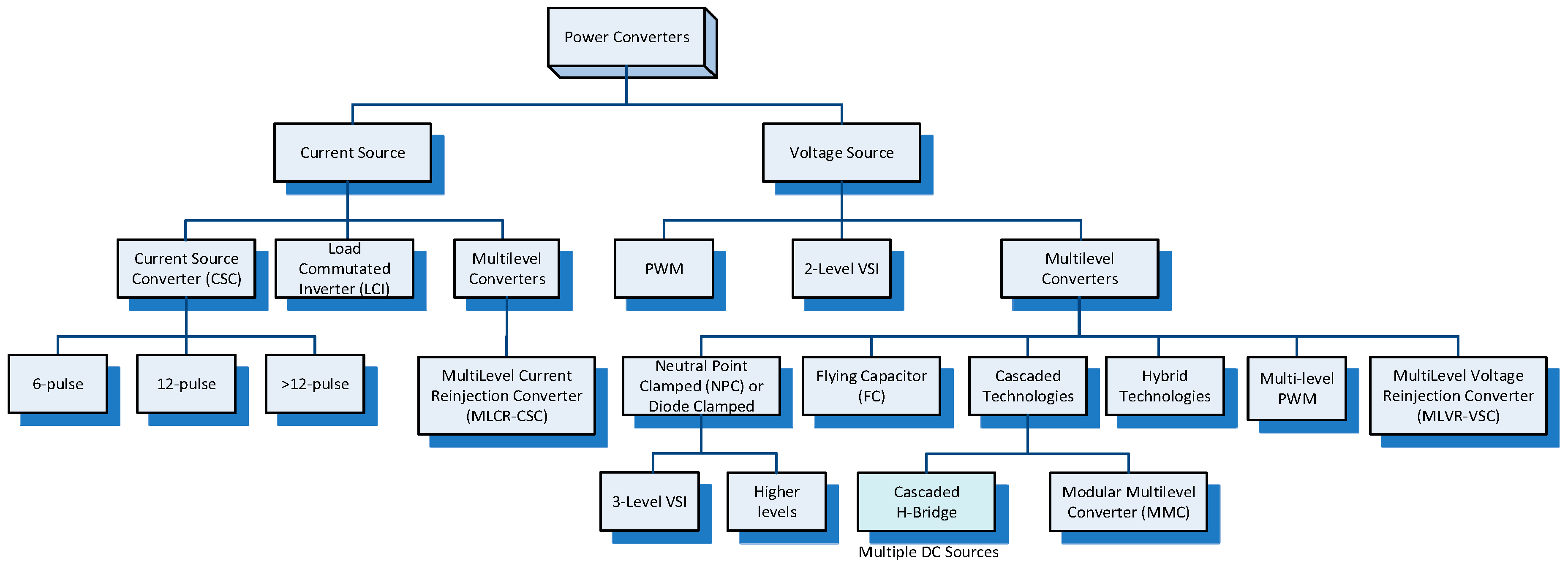
Figure 1. Alternating Current (AC)/Direct Current (DC) Converter classification.
Energies 13 04342 g001
Figure 2. Comparative cost of AC and DC transmission systems.
Energies 13 04342 g002
Figure 3. Basic Solid-state switches (a) Thyristor or Silicon Controlled Rectifier (b) Insulated Gate Bipolar Transistor.
Energies 13 04342 g003
Figure 4. Voltage and current rating of solid-state switches.
Energies 13 04342 g004
Figure 5. A 6-pulse (Graetz) bridge as a Current Source Converter (CSC).
Energies 13 04342 g005
Figure 6. A self-commutated Voltage Source Converter (VSC).
Energies 13 04342 g006
Figure 7. Two 6-pulse bridges forming a 12-pulse CSC using: (a) Three-winding converter transformer (b) Two two-winding converter transformers.
Energies 13 04342 g007
Figure 8. Arrangements of High Voltage Direct Current (HVDC) poles: (a) Monopole with metallic return path; (b) Monopole with earth return path; (c) Bipole with metallic return path; (d) Bipole with earth return path.
Energies 13 04342 g008
Figure 9. Operating states of a bipole HVDC link: (a) Normal operation; (b) Monopole due to a fault on one pole and using earth return; (c) Monopole operation and using metallic return path.
Energies 13 04342 g009
Figure 10. HVDC schemes for remote generation: (a) Unit connected HVDC scheme; (b) Group connected HVDC scheme.
Energies 13 04342 g010
Figure 11. Multiterminal HVDC schemes: (a) Parallel connected; (b) Series connected.
Energies 13 04342 g011
Figure 12. AC Current Waveforms of two 6-pulse bridges and the 12-pulse converter formed from the two: (a) AC current from Star/Star connected bridge; (b) AC current from Star/Delta connected bridge; (c) AC Current from the combination.
Energies 13 04342 g012
Figure 13. The commutation process in a 6-pulse bridge (a) Equivalent circuit for commutation between thyristor 1 and 3 (b) Voltage waveforms (rectification) (c) the current waveforms.
Energies 13 04342 g013
Figure 14. Basic three-phase Voltage Source Converter.
Energies 13 04342 g014
Figure 15. Voltage waveforms for the basic 6-pulse VSC using fundamental frequency switching. Waveforms (ac): Phase-to-DC-midpoint voltages; waveforms (df): Phase-to-phase voltages; waveform (g) Neutral voltage with respect to DC-midpoint; waveform (h) Phase-to-neutral voltage of phase a.
Energies 13 04342 g015
Figure 16. Basics of VSC: (a) One arm of the VSC; (b) The 2-level voltage waveform generated.
Energies 13 04342 g016
Figure 17. Sinusoidal Pulse Width Modulation (PWM).
Energies 13 04342 g017
Figure 18. PQ diagram of VSC operating area.
Energies 13 04342 g018
Figure 19. Three-phase PWM.
Energies 13 04342 g019
Figure 20. PWM with 3rd and 9th Harmonic: (a) Control Waveforms; (b) Synthesized Voltage waveform (Vsw) and its fundamental component (V1).
Energies 13 04342 g020
Figure 21. 3-Level Neutral-clamped converter.
Energies 13 04342 g021
Figure 22. Multilevel Modular Converter (MMC): (a) Topology; (b) Submodule.
Energies 13 04342 g022
Figure 23. Submodule Operation: (a) Circuit and schematic for the capacitor in-line; (b) Circuit and schematic for the capacitor by-passed.
Energies 13 04342 g023
Figure 24. Output voltage (fundamental frequency switching).
Energies 13 04342 g024
Figure 25. Arm switching pattern for a given output voltage.
Energies 13 04342 g025
Figure 26. Output voltage (fundamental frequency switching).
Energies 13 04342 g026
Figure 27. Generic VSC HVDC Converter Station.
Energies 13 04342 g027
Figure 28. MurrayLink VSC HVDC Converter Station.
Energies 13 04342 g028
Figure 29. Capacitor Commutated Converter.
Energies 13 04342 g029
Figure 30. Continuously Tuned AC Filter.
Energies 13 04342 g030
Figure 31. Active DC Filter.
Energies 13 04342 g031
Figure 32. Reinjection Scheme.
Energies 13 04342 g032
Figure 33. DC Circuit Breaker.
Energies 13 04342 g033
Table 1. Comparison of CSC based Line-Commutated Converter (LCC) and VSC HVDC systems.
CharacteristicLCC HVDCVSC HVDC
Store energy in inductancecapacitance
Semiconductorwithstands voltage in either polarityCombination can pass current in either direction
Semiconductor switchturned ON by control actionturned ON & OFF by control action
DC Voltagechanges polarity, reserves the power flow directionDirection does not change
DC Currentdirection does not changedirection changes to reverse the power flow
Turn-OFFcommutation relies on the external circuitindependent of external circuit
P & QP & Q dependentindependent P & Q control
Quadrants2 quadrant operation4-quadrant operation
Real Power capabilityVery HighLower than LCC
System StrengthRequires minimum SCR to commutate thyristorsOperates into weaker AC systems (or passive)
Overload capabilityGood Weak
DC line faultsCopes well. Control action can extinguish arcMore challenging as diodes provide path.
Harmonic generationSignificant, AC & DC harmonic filters requiredSmall, minimal filtering required.
Reactive powerNeededFine reactive power control in both directions
“Black” startrequires additional equipmentcapable
Table 2. Selected HVDC Schemes using Line-Commutated Converters [69].
NameYearTechnologyLengthDC VoltagePower Rating
Cable/OHL(kV)P (MW)
Gotland 11954Mercury-arc98/020020
Cross-Channel1961Mercury-arc64/0±100160
NZ Inter-Island 11965Mercury-arc40/571±250600
SACOI 11965Mercury-arc365/118±200200
Konti-Skan 11965Mercury-arc87/89±250250
Zhoushan1987Mercury-arc54−10050
Vancouver Isl. 11968Mercury42/33260312
Pacific DC Intertie1970Thyristor0/1362±5003100
Nelson River Bipole 1 21977Mercury-arc0/895±4501620
Skagerrak 11977Thyristor130/100±250500
Cahora Bassa 31979Thyristor0/1420±5331920
Hokkaido—Honshu1979Thyristor44/149±250300
Zhou Shan 41982Thyristor44/149+10050
Itaipu 11984Thyristor0/785±6003150
Nelson River Bipole 21985Thyristor0/940±5001800
Itaipu 21987Thyristor0/805±6003150
Fenno-Skan1989Thyristor200/33±400500
Rihand-Delhi1990Thyristor0/814±5001500
Quebec—New England1991Thyristor5/1100±4502250
NZ Inter-Island 21992Merc. & Thyr40/571+270/−3501240
Baltic Cable1994Thyristor250/12450600
Garabi HVDC2002Merc.0/0±702200
Three Gorges—Changzhou2003Thyristor0/890±5003000
Three Gorges—Guangdong 12004Thyristor0/980±5003000
Three Gorges—Guangdong2004Thyristor0/940±5003000
BassLink2006Thyristor298/72±400500
NorNed2008Thyristor580/0±450700
Yunnan–Guangdong2010Thyristor0/1418±8005000
XIangjiaba-Shanghai2010Thyristor0/1907±8006400
NZ Inter-Island 32013Thyristor40/571±3501200
Estlink 22014Thyristor157/14±450650
North-East Agra2017Thyristor0/1728±8006000
Nelson River Bipole 32018Thyristor0/1324±5002000
1 Later changed to be the first multiterminal link. 2 Largest mercury-arc valves ever made. The mercury-arc valves since replaced by thyristors. 3 First HVDC scheme ordered with thyristors, although operation was delayed. First to use a DC voltage greater than 500 kV. First HVDC link in Africa. 4 First HVDC Link in China.
Table 3. Selected HVDC Schemes using Voltage Source Converters [69].
NameYearTopologyLength
(km)
Switching Frequency DC VoltagePower Rating
Cable 1/OHL(Hz)(kV)P (MW)Q(MVAr)
Gotland VSC19992-level70/01950±8050 −55 to 50
Tjäreborg20002-level4.3/01950±97.2−3 to 4
Directlink20002-level59/01950±80180−165 to 90
Eagle Pass20003-level 20/01500±15.936±36
MurrayLink20023-level 3176/01350±150220−150 to 140
CrossSound20023-level 340/01260±150330±150
Troll A20052-level70/02000±6084−20 to 24
Estlink120062-level 4105/01150±150350±125
BorWin120092-level200/0 ±150400
Trans Bay Cable2010MMC85/0<150±200400±170
Nanao Island 52013MMC 610/32 ±160200/100/500
Zhoushan Isl. 72014MMC134/0 ±200400
INELFE2015MMC64.5/0 ±3202 × 1000
BorWin22015MMC200/0 ±300800
HelWin1,2015MMC130/0 ±250576
HelWin22015MMC130/0 ±320690
Dolwin12015Casc. 2-L 8165/0 ±320800
Dolwin22015MMC135/0 ±320900
Dolwin32018MMC162/0 ±320900
SylWin12015MMC205/0 ±300864
BorWin32019MMC160/0 ±320900
Zhangbei HVDC 92019 10 MMC170/648 11 ±5001500/4500
1 Cable length maybe a combination of undersea and land based cable. 2 Back-to-Back scheme using Diode Clamped/ Neutral-Point Clamped converter. 3 Active Neutral-Point Clamped. 4 Optimal Pulse Width Modulation (PWM). 5 3-terminal HVDC system in parallel to and AC interconnection. Switching devices: Injection-Enhanced Gate Transistor (IEGT) and Insulated Gate Bipolar Transistors (IGBT). 6 Multiterminal DC (MTDC). 7 5-terminal HVDC system. Provides voltage support to the existing ±50 kV 60 MW LCC-HVDC system on Sijiao Island to prevent commutation failure. 8 Cascaded 2-Level converters. 9 4-terminal HVDC system. 10 Stage 1. 11 Total length in the DC grid.