Article

Mathematical Model of Thermodynamic Processes in the Intake Manifold of a Diesel Engine with Fuel and Water Injection

1
Institute of Engineering and Technology, South Ural State University, 454080 Chelyabinsk, Russia
2
Atmospheric Plasma Division, Institute for Plasma Research, Gandhinagar 382428, Gujarat, India
*
Author to whom correspondence should be addressed.
Energies 2020, 13(17), 4315; https://doi.org/10.3390/en13174315
Submission received: 20 July 2020 / Revised: 7 August 2020 / Accepted: 17 August 2020 / Published: 20 August 2020

Abstract

:
The article presents the results of a study aimed at creating a mathematical model of thermodynamic processes in the intake manifold of a forced diesel engine, taking into account the features of simultaneous injection of fuel and water into the collector. In the course of the study, the tasks of developing a mathematical model were solved, it was implemented in the existing software for component simulation “Internal combustion engine research and development” (ICE RnD), created using the Modelica language, and verification was undertaken using the results of bench tests of diesel engines with injection fuel and water into the intake manifold. The mathematical model is based on a system of equations for the energy and mass balances of gases and includes detailed mathematical submodels of the processes of simultaneous evaporation of fuel and water in the intake manifold; it takes into account the effect of the evaporation of fuel and water on the parameters of the gas state in the intake manifold; it takes into account the influence of the state parameters of the working fluid in the intake manifold on the physical characteristics of fuel and water; it meets the principles of component modeling, since it does not contain parameters that are not related to the simulated component; it describes the process of simultaneous transfer of vapors and non-evaporated liquids between components; and it does not include empirical relationships requiring data on the dynamics of fuel evaporation under reference conditions. According to the results of a full-scale experiment, the adequacy of the mathematical model developed was confirmed. This model can be used to determine the rational design parameters of the fuel and water injection system, the adjusting parameters of the forced diesel engine that provide the required power, and economic indicators, taking into account the limitations on the magnitude of the mechanical and thermal loads of its parts.

1. Introduction

The modern economy requires the maximum reduction of time and money spent on the development and preparation of production, the analysis of the object’s technical condition at all stages of the life cycle, and the fast introduction of changes to the products design parameters and operation modes [1]. The development and implementation of digital twin technology can significantly increase the effectiveness of research and development by maximizing the replacement of costly and time-consuming real product tests with virtual ones without sacrificing their quality. This fully applies to reciprocating internal combustion engines—the main sources of mechanical energy for operating land vehicles [2]. Most researchers believe that the model should implement simulation methods [3], that is, with the required accuracy to describe the processes as they would actually take place and with which it is possible to conduct computational experiments in order to obtain information about the dynamics system. Digital twins and their underlying simulations can help solve a wide range of engine design challenges. One of the urgent tasks is to increase the power of reciprocating engines while maintaining weight, dimensions and resource indicators, meeting the restrictions on emissions of harmful substances with exhaust gases.
One of the known methods of forcing transport diesel engines is the simultaneous injection of fuel and/or water into the intake manifold [4,5]. The main advantage of this method is its simplicity of design and high efficiency. Analysis of works devoted to the study of the effect of fuel and water vapor on the performance of diesel engines [6,7] shows that they mainly consider the processes in the combustion chamber. However, for the correct setting of the initial conditions in the combustion chamber, especially in transient modes of engine operation, a gas-dynamic calculation of the processes in the gas-air duct is necessary. For this, high-precision CFD (computational fluid dynamics) methods [8] can be used, however, they are characterized by high labor intensity, which makes it difficult to use them in solving optimization problems.
The most widespread methods in practice are one-dimensional simulation of processes in the gas-air duct. Since a typical specification of the problem of one-dimensional modeling of engine processes usually includes more than 1000 equations, half of which are differential, such models are implemented in the form of specialized software. The GT-Suite [9], AVL Boost [10], Ricardo Wave [11], Siemens AmeSim [12] programs have found wide application for the simulation of reciprocating internal combustion engines in the engine building industry. Usually, such programs allow you to enter fuel into the intake manifold, which allows you to simulate engines with external mixture formation. For example, in the AVL Boost program there are the elements “plenum” and “pipe”, which take into account the presence of fuel vapors, and the “injector” element allows you to inject liquid fuel into the gas-air path and set the characteristics of its evaporation. Similar components are available in Ricardo Wave (“orifice” and “injector”) and Siemens Amesim (“eng_pipe” and “eng_injector”). The multicomponent composition of the working fluid in the elements of the gas-air duct does not include liquid and, respectively, the mathematical description does not include the processes of its evaporation (except for fuel for engines with external mixture formation) and transfer from one component to another. The GT-Suite program additionally includes models of liquid evaporation during cavitation and fuel evaporation in the combustion chamber, while liquid and vapor fluids may not be combined in the channels of the gas-air duct. Water vapor is a component of the combustion products and not the result of the evaporation of the injected water. There are separate publications, for example [13], which describe the use of GT-Suite for calculating engines with water injection into the intake manifold, but there is no information on how the process of water evaporation is simulated.
The mathematical model of fuel evaporation of the GT-Suite program is based on an empirical dependence, which requires data on the dynamics of fuel evaporation under reference conditions and the crankshaft speed. The latter requirement is at odds with the concept of component modeling, since the “cylinder” or “volume” components cannot and should not “know” the crankshaft speed. In addition, the model does not take into account such factors as the diameter and number of spray holes, liquid density. The AVL Boost mathematical model of fuel evaporation is based on the assumption that components with higher volatility evaporate at lower temperatures (approx. 50 °C), components with lower volatility evaporate at higher temperatures (approx. 170 °C). In order to take this effect into account the actual amount of injected fuel is split into different “fuel-type packages” where each package has different evaporation properties depending on the user-specified distillation curve. The convective mass transfer coefficient is calculated using the Sherwood number, to determine which it is necessary to know the current values of the diffusion coefficient of the package in the mixture, Reynolds number and Schmidt number at the injector position, the correct determination of which in unstable conditions of the gas–air path engine for each package is complex. Similar problems occur in other well-known mathematical models (Ricardo Wave, Siemens Amesim, etc.).
In theory it is possible to create custom components in which the processes of simultaneous evaporation of fuel and water are adequately simulated; however, it is impossible to simulate the processes of transfer of fuel droplets between components, since this requires changes to the basic foundations implemented in programs, which is impossible because of their proprietary code.
Thus, solving the problem of synthesizing simulation models of engines boosted by simultaneous injection of water and fuel into the intake manifold is difficult due to the lack of reliable mathematical models describing the processes of simultaneous evaporation of water and fuel, transfer of their vapors and non-evaporated liquid between components. The aim of the study was to solve the scientific problem of developing such a model. This model can be implemented into well-known mathematical models describing in a one-dimensional formulation the processes in the gas-air duct, which are developed, validated and implemented in the form of software (that is, the task of developing a complete mathematical model of the engine is not undertaken).
The model developed includes detailed mathematical submodels of the processes of simultaneous evaporation of fuel and water in the intake manifold; it takes into account the effect of the evaporation of fuel and water on the parameters of the gas state in the intake manifold; it takes into account the influence of the parameters of the state of the working fluid in the intake manifold on the physical characteristics of fuel and water; it meets the principles of component modeling, since it does not contain parameters that are not related to the simulated component; it describes the process of simultaneous transfer of vapors and non-evaporated liquids between components; and it is based on basic equations of physics, and not on empirical dependencies that require data on the dynamics of fuel evaporation under reference conditions. Together, these features of the mathematical model distinguish it from the known ones.

2. Main Part

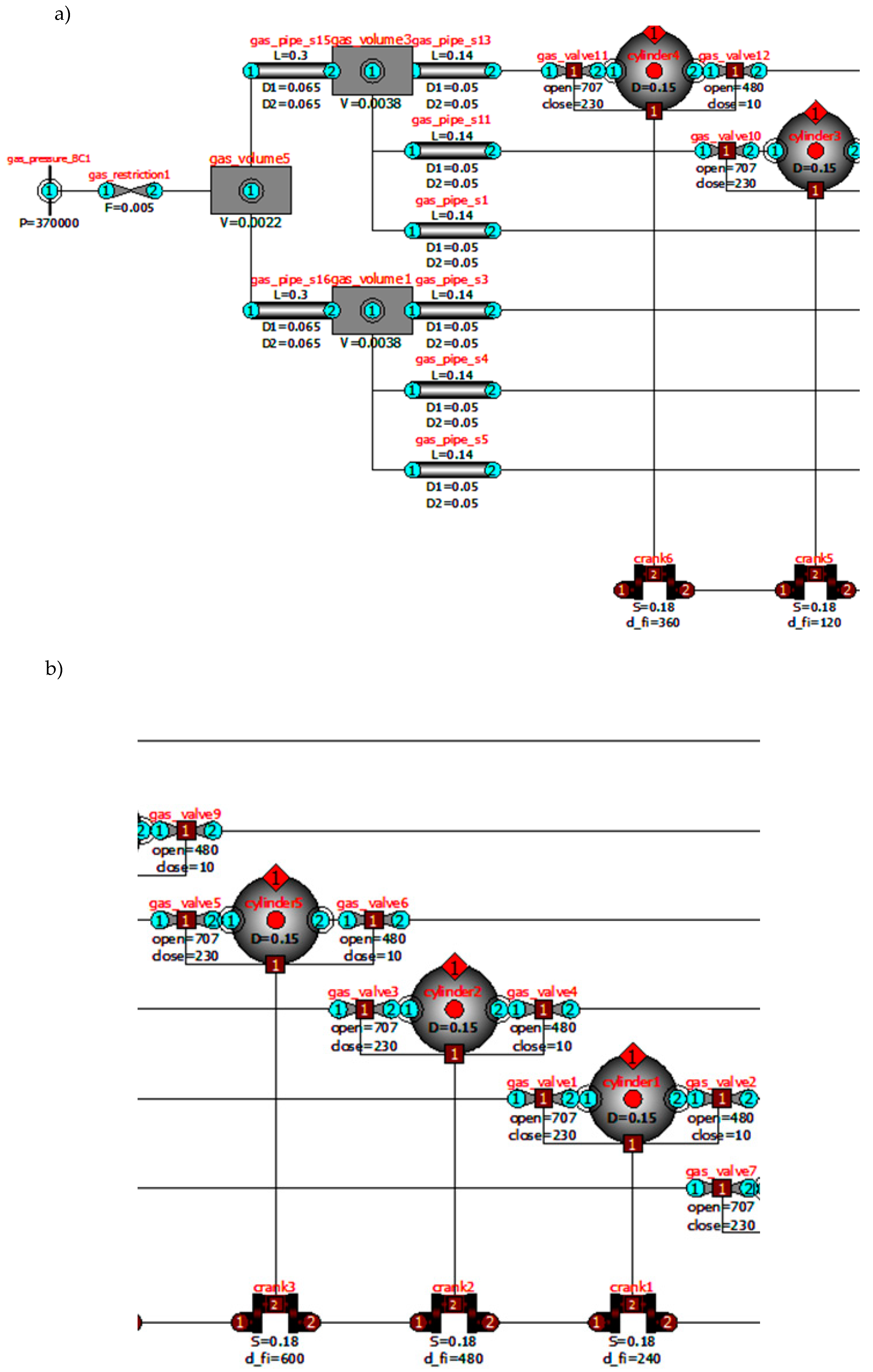
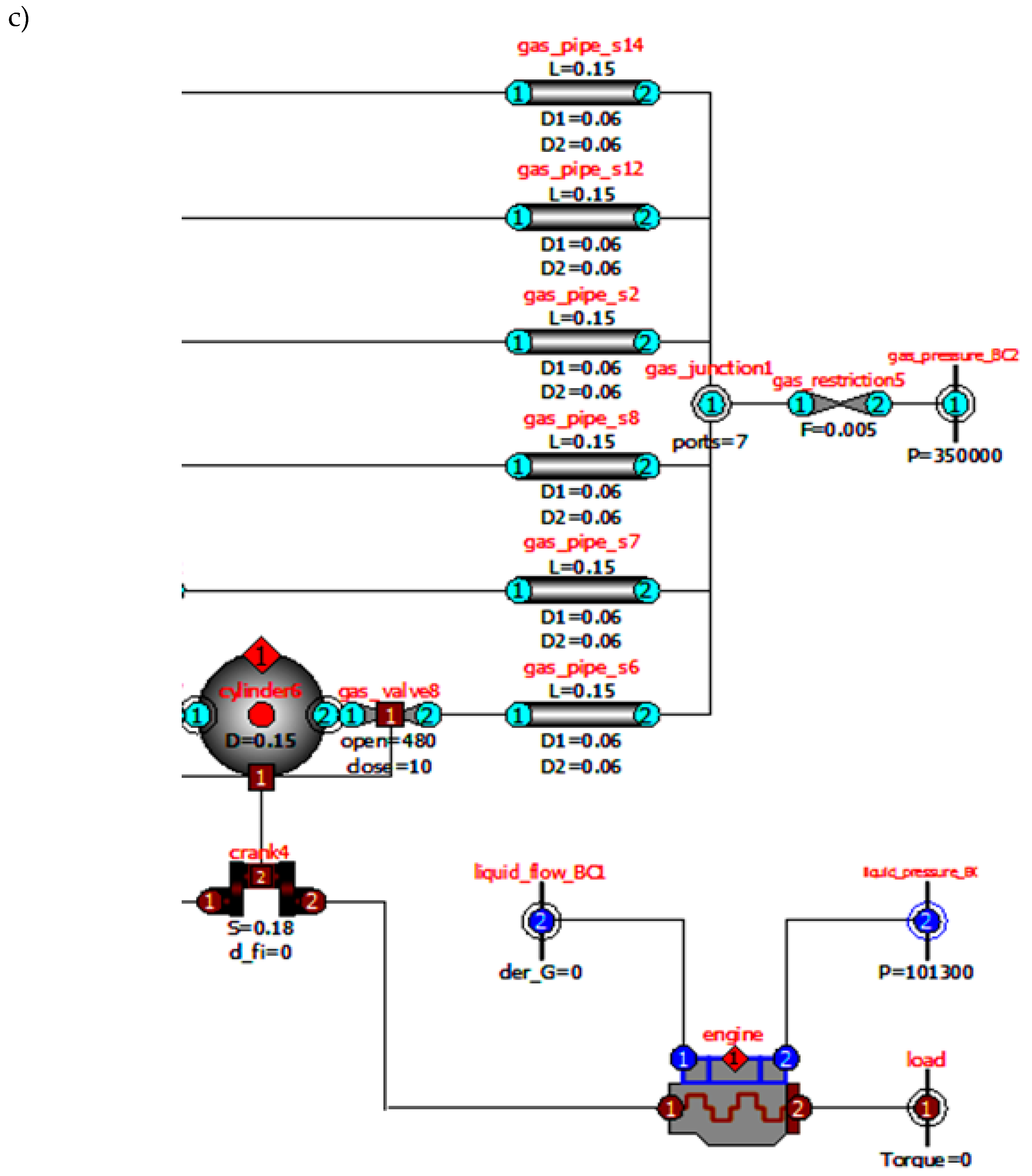
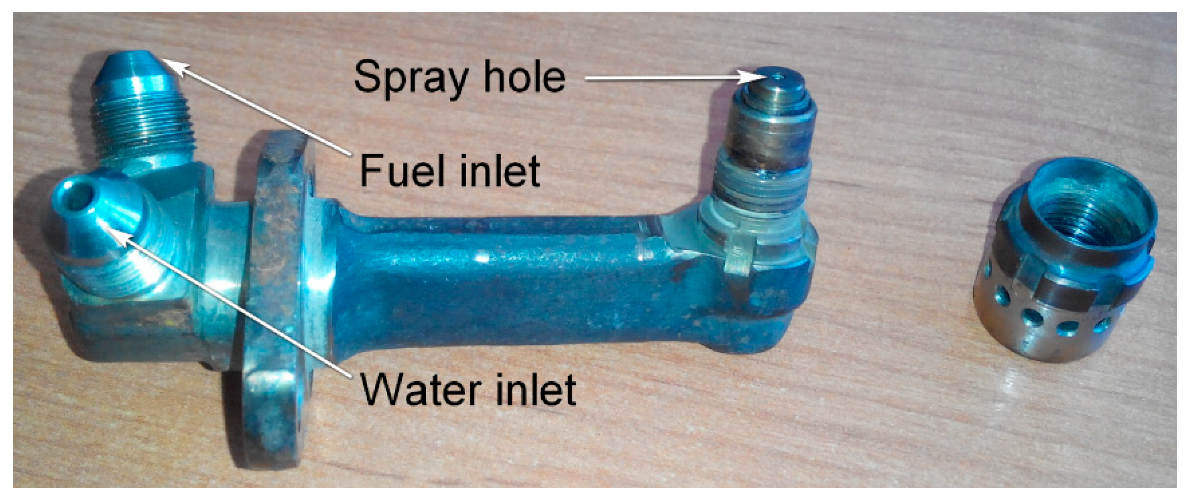
2.1. Developed Mathematical Model

Analysis of the existing methods of gas and thermodynamics, known mathematical models for one-dimensional gas-dynamic calculation of the gas–air path of piston engines, indicates the appropriateness of using phenomenological models such as Lyshevsky’s [14], Razleitseva’s [15], Kuleshov’s [16], Hiroyasu’s [17] for modeling processes in the intake manifold of a diesel engine with fuel and/or water injection, developed for the conditions of fuel injection into the combustion chamber. According to these models, the camera volume is divided into separately modeled zones in which interconnected processes take place. For example, according to Kuleshov, the relative rate of evaporation of the liquid for the i-th zone:
d σ u i d τ = [ 1 ( 1 b u i τ u i ) 1.5 ] σ z i τ u i
τ u i = τ s τ s 0 i
b u i = Y K i D 32 2
where τ is time; τ s is the current time; τ s 0 i is the time of fuel getting into i-th zone; τ u i is current time from the start of injection; σ z i is the fraction of fuel in the i-th zone; K i is the evaporation constant in the i-th zone; D32 is the Sauter average droplet diameter; b u i is relative constant of evaporation in the i-th zone; Y is a function that corrects unaccounted factors and errors in assumptions made.
The total evaporation rate is defined as the sum of the evaporation rates in all zones. The constants of fuel evaporation in different zones are determined as follows:
K u i = 4 10 6 N u D D p p s ρ l
D p = D p 0 T k T 0 p 0 p
where: N u D is the Nusselt criterion for the diffusion process; D p is the vapor diffusion coefficient; D p 0 is vapor diffusion coefficient under the conditions p 0 = 0.1 MPa, T 0 = 293 K; T k is the temperature of the drop; p is the current pressure; ρ l is the fluid density; p s is the vapor pressure.
Most researchers assume that the initial diameter of a liquid droplet is equal to the diameter of the spray hole [18]. To describe the frequency curve of the droplet size distribution, the P. Rosin and E. Rammler equation [19] is well suited:
d i d z z 3 = n a m n z n 1 e ( z a m ) n
where: z is the characteristic droplet size; i is the number of drops of size z ; n and a m are empirical indicators.
In models similar to (1–6), periodic injection of liquid is considered and the diameter of all drops is assumed to be the same at every moment of time and changing simultaneously. According to Razleitsev [20], under diesel conditions, the dispersion of spraying is characterized by an average droplet diameter, which makes it possible to significantly simplify the task of modeling the dynamics of liquid evaporation in the intake manifold. However, the model of Razleitsev does not explicitly show the temperature of the medium, in addition, it is designed for cyclical rather than continuous fuel supply (i.e., τevap → ∞). It can be taken as the basis for a model of fuel and water injection into the intake manifold, since, unlike other known models (AVL Boost, GT-Suite, etc.), and it takes into account the characteristics of the atomizer, the fuel density and the parameters of the gas state. In the simulated volume, fully complies with the principles of the component approach in the synthesis of simulation models, does not require the determination of parameters that depend on the characteristics of the gas flow in the reservoir.
The basis of the mathematical model of thermodynamic processes in the intake manifold of a diesel engine is a system of equations of energy and mass balances [21] of a mixture of air, exhaust gases (entering the collector when being thrown from the combustion chamber), water vapor and fuel (hereafter gas):
d H d τ d m g d τ u + d Q int d τ + d Q w a l l d τ + d U d τ = 0
where m is the manifold gas mass; U is the internal gas energy; u is specific internal energy of gas; d H d τ is the enthalpy flow due to mass transfer; d Q int d τ is the drain of energy due to heating and evaporation of water and fuel; d Q w a l l d τ is the energy flow through the walls; d U d τ is the change in the internal energy of the gas.
d m g d τ + d m i n d τ + d m o u t d τ + d m int d τ = 0
where d m i n d τ is the mass flow of gas flowing into the reservoir; d m o u t d τ is the gas mass flow from the manifold; d m int d τ is the change in mass of gas due to the evaporation of water and fuel.
The system of equations of energy and mass gas balances (7) and (8) is supplemented by the gas state equation. Energy flow due to evaporation of water and fuel:
d Q int d τ = d Q h f d τ + d Q e f d τ + d Q h w d τ + d Q e w d τ
where d Q h f d τ , d Q h w d τ are the energy drains due to heating droplets of fuel and water, respectively, to a boiling point; d Q e f d τ , d Q ew d τ are the energy drains due to evaporation of fuel and water, respectively.
The amount of apparent heat spent on heating the fuel droplets to a boiling point:
d Q h f d τ = d m l f d τ c l f ( T e f T l f )
where m l f is the mass of liquid fuel; c l f is the specific heat of liquid fuel; T e f is the boiling point of the fuel; T l f is the temperature of the liquid fuel.
The amount of latent heat spent on the evaporation of fuel:
d Q e f d τ = d m e f d τ q b f
where m e f is the mass of evaporated fuel; q b f is the specific heat of vaporization of the fuel.
The equations for water can be defined similar to (10) and (11):
d Q h w d τ = d m l w d τ c l w ( T e w T l w )
d Q e w d τ = d m e w d τ q b w
where m l w is the mass of liquid water; c l w is the specific heat of liquid water; T e w is the boiling point of water; T l w is the temperature of liquid water; m e w is the mass of evaporated water; q b w is the specific heat of vaporization of water.
Enthalpy flow due to mass transfer:
d H d τ = d m i n d τ h i n + d m o u t d τ h o u t
where h i n and h o u t are the specific enthalpy of inflowing and outflowing gas, respectively.
The physical properties of a mixture of air, water vapor and fuel depend on its temperature. For a mixture of air, water vapor and fuel in the intake manifold, the average values of the specific physical indicators are determined using the weighted average.
The boiling point of water, depending on pressure (MPa):
T e w = 273 + 179.5 p 0.239   K .
Since diesel fuel is a mixture of hydrocarbons having a different boiling point (180–360 °C [22]), when performing calculations it is recommended to use a temperature at which 50% of the fractions are distilled off (for diesel summer and winter fuels Tef = 280 °C). For water in the liquid phase, the specific heat capacity in the temperature range 0–90 °C varies insignificantly (from 4213.8 J/(kg K) to 4205.8 J/(kg K) [23]), therefore it can be assumed constant and equal to cv = 4210 J/(kg K). For diesel fuel in the liquid phase, the specific heat is:
c l f = 0.0043 T 2 + 0.1704 T + 1786   J / kg K .
The fuel temperature in Equation (17) can be taken equal to the arithmetic mean between the initial and Tew. The specific heat of water vaporization in the pressure range 0.1–0.5 MPa is approximated by the linear dependence [24]:
q b w = ( 1.54 0.1241 p ) 10 6   J / kg .
For diesel fuel in the liquid phase, the specific heat of vaporization at the boiling point is:
q b f = 379102 0.3068 T e f 2 89.4 T e f   J / kg .
To simulate the process of evaporation of jets of liquids in the intake manifold, we used the assumption that the dynamics of the process of evaporation of a liquid repeats the dynamics of its injection, but with a time shift equal to the time of complete evaporation of the droplet:
d m e d τ = d e l a y ( d m l d τ , τ e )
The time of complete evaporation of a drop is inversely proportional to the relative constant of evaporation:
τ e = 1 b e v a p
which, in turn, is determined by the Razleitsev method adapted for the conditions of continuous injection [15].
The average rate of fluid flow from the nozzle atomizer with continuous injection:
U 0 = m l n ρ l π D c 2 i c 20
where ρ l is the density of the liquid; Dc is the diameter of the nozzle holes; ic is the number of coop holes.
M-criteria:
M = μ l ρ g D c σ l
where μ l is the dynamic viscosity coefficient of the liquid; ρ g is the gas density in the combustion chamber; σ l is the surface tension coefficient of the liquid.
Weber criteria:
W e = U 0 2 ρ l D c σ l
The average surface diameter of liquid droplets:
D 32 = E 32 D c M 0.0733 ( ρ g ρ l W e ) 0.266
where ρ g is the gas density in the combustion chamber; E 32 = 1.7 is the empirical coefficient in the original Razleytsev’s methodology [15].
Relative constant of fuel evaporation:
b e v a p = k e v a p p D 32 2
where k e v a p is the constant depending on evaporation conditions (assumed k e v a p = 1).
In Equations (21)–(25), the physical characteristics of a specific liquid (fuel or water) should be used, including as a function of temperature. The dependencies obtained on the basis of the IAPWS (International Association for the Properties of Water and Steam) formulations are the most accurate, however, according to Lyshevsky [14], and in the range of conditions of the combustion chamber and especially the intake manifold, these properties can be considered constant.
When calculating, it must be taken into account that not all injected fuel or water can evaporate in the intake manifold. To control this situation, the time is calculated during which the gas flow passes the distance Linj from the place of installation of the nozzle to the exit of the intake manifold:
τ L = L i n j U g = 1 p | d m p d τ | p ρ g A i n j
where U g is flow rate at the nozzle installation site; A i n j is cross-sectional area of the intake manifold at the nozzle installation site.
If τe > τ L , the non-evaporated fuel or gas flows into the neighboring element of the gas–air path, where the evaporation process continues.
The temperature of the gases in the manifold is determined from the equation:
d T d t = d U d t 1 c v ( T , C ) m g
where C —component concentration vector;
In general terms, the flow of mass of gas flowing in or out of the intake manifold is described by the well-known formula:
d m g d τ = μ A p i n R T i n 2 k R T i n k 1 ( 1 p o u t p i n ) 1 1 k
where μ A is effective cross-sectional area; p i n and T i n are gas pressure and temperature before and after the cross-section, respectively; k is adiabatic exponent; p o u t —gas pressure over the cross section (must not exceed critical for a given flow regime):
p c r i t = p i n ( 2 k + 1 ) k k 1
For several interconnected elements of the gas–air path, the mathematical model is supplemented by the equations of the balance of gas flow and pressure at the joints:
1 c ( d m c d t ) = 0
p 1 = p 2 = = p p ,
where c is the number of connections; d m c d t —gas consumption through each connection.
Through the connection, the values of the temperature variables, the concentration vector of the components and the specific enthalpy of the gas are transmitted, taking into account the direction of flow.

2.2. Verification of the Mathematical Model

Developed mathematical models were implemented into developed software. Since the complete model of a diesel engine, in addition to the mathematical description of the gas-air path, should include submodels of processes in the combustion chamber, the crank and gas distribution mechanisms, heat transfer in structural elements and with the environment, a code analyzer-optimizer, a mathematical solver, etc., the “Combustion Engine Research and Development” (ICE RnD) software, previously developed by A.A. Malozyomov and G.A. Malozyomov were taken as the basis. A detailed description of the program and the mathematical models implemented in it is given in [25,26]. The program is written in the language Modelica [27], which makes it easy enough to make changes to the code, and it is a class library from which simulation models of a diesel engine of any configuration are compiled using the graphical interface. The program classes that describe the processes in the elements of the gas–air path (volumes, pipes, connecting channels, combustion chamber) were modernized and supplemented to provide the possibility of modeling a diesel engine with fuel and water injection into the intake manifold [28], namely:
  • the base class “volume” was supplemented by a description of the process of evaporation of fuel and water and its effect on the parameters of the state of gases in the combustion chamber;
  • in the remaining base classes, including component relationships, additional variables were included—the concentration of fuel and water vapor;
  • the base class “cylinder” was supplemented by descriptions of the combustion process of fuel vapor coming from the intake manifold, and the effect of water vapor and combustion products of fuel vapor on the combustion performance the Vibe equation of the main portion of fuel injected into the combustion chamber [28].
When calculating a diesel engine with fuel and/or water injection into the intake manifold, the problem of choosing the main design parameters of the fuel and water injection system and rational values of their mass supply is usually solved in order to ensure the specified power values with the minimum possible increase in the maximum values of temperature, pressure and rate of pressure rise gases in the combustion chamber. This article presents the calculation results confirming the adequacy of the developed mathematical model.
The initial data, boundary and initial conditions for the calculation corresponded to the design and operational characteristics of the 12CHN15/18 diesel engine (Uraltrak, Chelyabinsk, Russia). The dimensions of the collector and the gas and thermodynamic conditions in it by default corresponded to the averaged parameters of a real diesel engine operating at maximum power at a nominal crankshaft speed. The diameter of the spraying hole of water is 0.5 mm, of fuel is 0.1 mm, the continuous supply is reduced to one operating cycle of a diesel engine, water is 0.15 g, and fuel is 0.05 g. The temperature of the injected water and fuel is 50 °C. Both nozzles are installed at a distance of 0.6 m in front of the inlet valve seat of the first cylinder. The number of spray holes for both fuel and water is one at a time.
The engine design scheme created in the modified ICE RnD program is shown in Figure 1. The parameters of the gas turbine boost were specified by the boundary conditions; for the simulation of fast-flowing processes lasting less than 1 s, and this is acceptable, taking into account the inertia of the turbocharger. The injection of fuel and water was carried out after stabilization of the diesel parameters, after 2 s. after the start of the calculation. The parameters and indicators of the components of the left and right row of cylinders were assumed to be identical, therefore, the calculation was carried out only for one row, shown in Figure 1. Since the calculation task did not include determining the loads on the elements of the crank mechanism, this simplification is acceptable.
To verify the mathematical model developed, we used the data obtained by M. Grankin [5,28] during experimental studies of a 12ChN15/18 diesel engine equipped with a fuel and water injection system into the intake manifold. Since the developers of the engine are mainly interested in the main parameters of the purpose (power and fuel efficiency) and the thermal-mechanical loading of the parts of the crank mechanism and the cylinder-piston group, during the experiment, the parameters of the purpose and indicator diagrams of the gas pressure in the combustion chamber were determined.
The appearance of the nozzle for injection of water and fuel is shown in Figure 2. The experimental conditions corresponded to the settings of the test simulation model. Fuel and water were supplied to the nozzle separately and mixed after leaving the spray hole. The diameter of the spray hole of water is 0.5 mm, fuel is 0.1 mm, continuous supply reduced to one operating cycle of diesel, water is 0.15 g, and fuel is 0.05 g. Both nozzles were installed at a distance of 0.6 m in front of the inlet valve seat of the first cylinder.
Figure 3 shows a comparison of the calculated and experimental indicator diagrams of the gas pressure in the combustion chamber for the maximum diesel power mode at a speed of 2100 min−1. To fulfill the restrictions on the maximum gas pressure in the combustion chamber, the fuel injection advance angle was reduced by 4 degrees of crankshaft rotation compared to the base diesel engine. In addition, the figure shows the calculated and experimental indicator diagrams of the gas pressure of a diesel engine without the injection of fuel and water into the intake manifold.
From the results of the analysis, it was concluded that at the level of significance α = 0.01, there is no significant difference between the experimentally determined values of the gas pressure in the combustion chamber and their simulations; the mathematical model adequately describes the experimental data. The calculated value of the pair correlation coefficient is 0.992, which indicates the degree of reliability of the developed mathematical model sufficient for engineering calculations.
Figure 4 shows a comparison of the experimental and calculated values of brake-specific fuel consumption of the engine at speed characteristic modes with and without fuel and water injection into the intake manifold.
From the data shown in Figure 3 and Figure 4, it follows that at a given level of significance, the pair correlation coefficient of the experimental and calculated values of the quantities is 0.994 and 0.985, respectively. The absolute error in calculating the effective engine power does not exceed 13 kW (1.6%).
Figure 5 shows the dynamics of changes in the concentration of water vapor obtained using the developed model and the CFD model created by M. Grankin [28] using the OpenFOAM software [29]. In the course of the calculation, water injection was simulated with a temperature of 50 °C through a hole with a diameter of 0.5 mm and a flow rate of 0.015 kg/s (the moment of injection start—0.1 s from the beginning of calculation) into a pipe with a diameter of 0.14 m and a volume of 0.017 m3, into which, under a pressure of 375 kPa air was supplied with a temperature of 530 K, the outlet counter pressure was 365 kPa (which approximately corresponds to the conditions of the intake manifold of the tested diesel engine operating at maximum power).
As can be seen from Figure 5, the developed mathematical model makes it possible to obtain results that are quite close to the data of CFD calculations. The differences are primarily due to the fact that the developed model does not take into account the statistics of the distribution of drops by diameter, that is, the presence of small drops at the initial moment of injection, which begin to evaporate almost immediately.
Thus, the developed mathematical model adequately reflects the features of the processes of an engine equipped with a fuel and water injection system into the intake manifold and can be used in engineering calculations to create such systems.

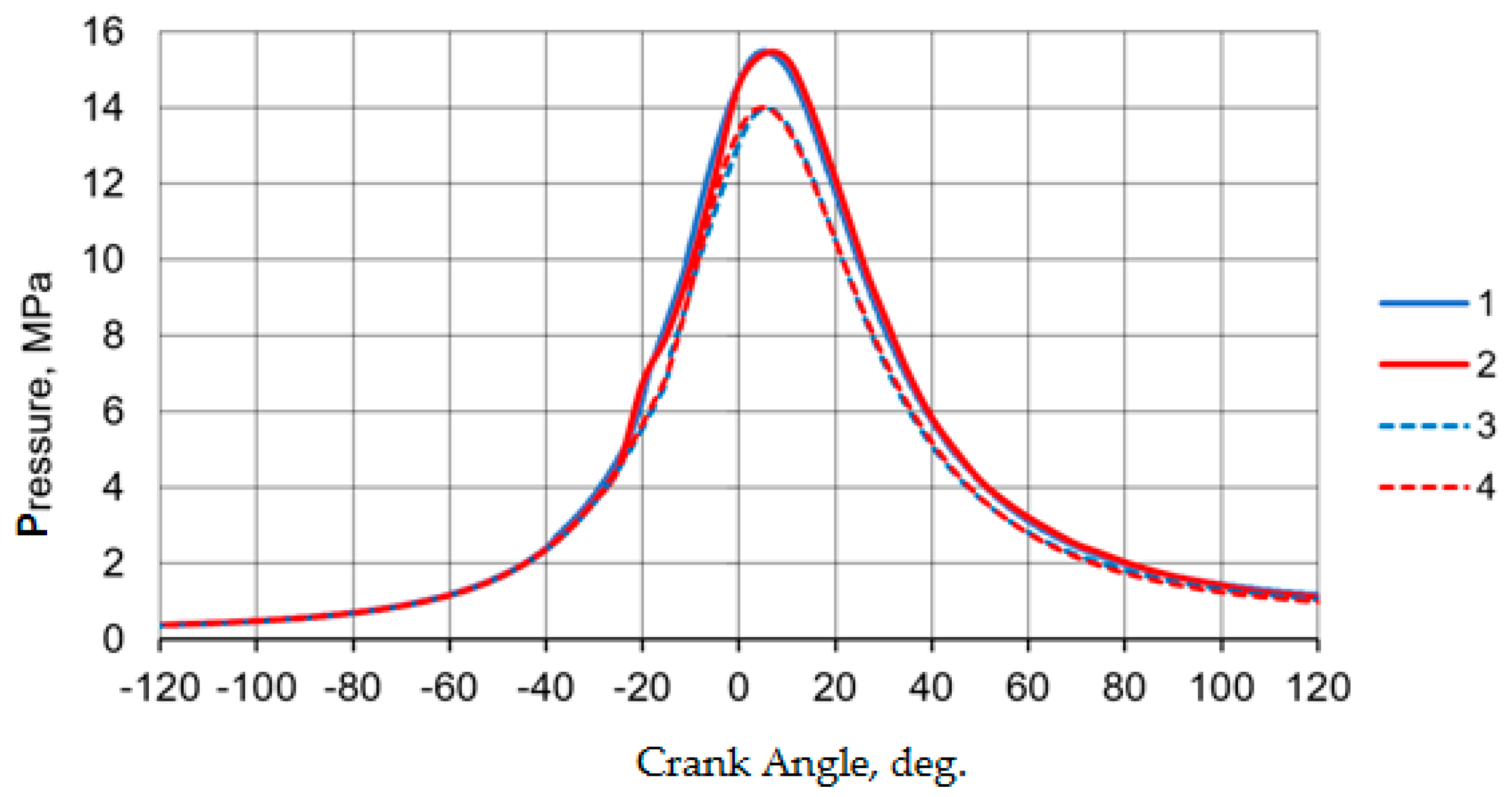
3. Calculation Results and Discussion

Analysis of the calculation results, using the developed mathematical model, implemented into a complex simulation model of a diesel engine, makes it possible to reveal the general patterns of the influence of various factors on the characteristics of engine processes with water and fuel injection into the intake manifold, which can be illustrated with specific examples.
A preliminary calculation showed that the farther from the nozzle along the length of the gas-air duct its element is, the greater the delay in the change and subsequent stabilization of the vapor concentration. For the inlet channels of the head of the first (counting from the injector installation site) cylinder, the delay is 0.2–0.3 s. (Figure 6).
The amplitude of the change in vapor concentration depends on the volume of the element, gas and thermodynamic conditions, the largest amplitude (±0.00016 kg/kg or ±2.4%)—at the place where the nozzle is installed. In the channels of the cylinder head, the concentration of vapors is practically constant and decreases by up to 0.8% at the moment the intake valve opens. The slight difference in the rate of concentration change is caused by the longer duration of the water evaporation delay, which is clearly expressed for the location of the nozzles and is practically zero for the inlet of the head. The stepped nature of the change in the concentration of vapors in the inlet channel of the cylinder head is explained by the cyclic opening and closing of valves and, accordingly, the dynamics of gas flow in its volume.
The effect of the evaporation of fuel and water on the temperature of the gases in the elements of the gas-air duct is shown in Figure 7. It should be noted that the average temperature of the gases in front of the inlet bodies is lower than at the place of installation of the nozzles. This is caused by heat loss through the walls of the elements of the gas-air path, which are taken into account in the calculation. The gas pressure does not change as noticeably as the temperature, although some reduction occurs.
Figure 8 shows that the duration of the transition process from the moment the fuel and water supply to the intake manifold starts to stabilize the torque value is 0.2–0.3 s. This must be taken into account if the results of a one-dimensional calculation of processes in the gas-air duct are used to set the boundary conditions when simulating processes in a combustion chamber (for example, in CFD calculations).
The period of delay in the evaporation of fuel and water should not exceed the time for drops of fuel to reach the outlet from the manifold. Droplets entering the combustion chamber can adversely affect engine performance due to additional cooling of the cylinder walls due to their evaporation. Based on this condition, as well as depending on the value of the maximum cyclic fluid supply, the maximum permissible diameter of the spray holes and the distance from the nozzles to the outlet from the manifold should be determined. Figure 9 shows the influence of the temperature of gases at the inlet to the intake manifold on the concentration and the period of delay in the evaporation of fuel and water.
For the engine under consideration, the time for fuel droplets to reach the exit from the manifold is 0.024–0.026 s, and the maximum permissible diameter of the spray holes is 0.6 mm, the time for water droplets to exit the manifold is 0.024–0.030 s, the maximum permissible diameter spray holes 0.7 mm. As can be seen from Figure 9, the time of evaporation of liquid droplets in the considered range of temperatures of gases at the inlet to the intake manifold does not exceed the time for the non-evaporated droplets to reach the outlet from the manifold.
When developing an engine, it is important to comply with the limitations on the mechanical loading of its parts, which can be estimated by the value of the maximum gas pressure in the combustion chamber. Figure 10 shows the dependence of the maximum gas pressure in the combustion chamber on the cyclic supply of fuel and water to the intake manifold. Restrictions can be fulfilled by changing the angle of the start of injection of the main portion of fuel into the combustion chamber. The rational value of the angle (4 degrees of crankshaft rotation less than that of the engine without fuel and water injection into the intake manifold) was justified during the calculation.
Using a simulation model, the power dependences (relative to the nominal value for a serial diesel engine) of the engine on the supply of fuel and water to the intake manifold were obtained, shown in Figure 11.
It should be noted that the dependences were obtained for specific gas and thermodynamic conditions (pressure, temperature and gas velocity in the intake manifold) corresponding to the maximum power mode of a particular diesel engine. For other engine models and modes of operation, the rational values of the design parameters may be different.
In general, the nature of the dependences obtained is expected, consistent with practical experience and available experimental data. The developed mathematical model, described in this article and implemented in a complex engine simulation model, makes it possible to evaluate the quantitative characteristics of these dependencies and, on their basis, to determine the rational design parameters of the fuel and water injection system into the intake manifold. For example, in the framework of this study, it was possible to increase the maximum engine power by 13%, while reducing the specific effective fuel consumption by 2% and ensuring that the maximum pressure of the gases in the combustion chamber is met.

4. Conclusions

In the course of a theoretical study, a mathematical model of working processes in the elements of the gas-air duct of a diesel engine with forcing by simultaneously supplying fuel and water to the intake manifold was developed, which:
  • includes detailed mathematical submodels of the processes of simultaneous evaporation of fuel and water in the intake manifold;
  • takes into account the influence of the process of evaporation of fuel and water on the parameters of the gas state in the intake manifold;
  • takes into account the influence of the parameters of the state of the working fluid in the intake manifold on the physical characteristics of fuel and water;
  • complies with the principles of component modeling, since it does not contain “unnecessary” parameters that are not related to the component being modeled;
  • describes the process of simultaneous transfer of vapors and non-evaporated liquids between components;
  • is based on basic equations of physics, and not on empirical dependencies that require data on the dynamics of fuel evaporation under reference conditions.
Together, these features of the mathematical model distinguish it from the well-known ones implemented in the form of software widely used in the engine building industry (AVL Boost, GT-Suite, Ricardo Wave, Siemens Amesim, etc.).
The practical value of the mathematical model created for the engineering and scientific community lies in the fact that it can be used in conjunction with known submodels of processes in systems and mechanisms of a reciprocating internal combustion engine for the synthesis and subsequent use of complex simulation models and digital twins of diesel modifications with forcing by changeable injection of fuel and water into the intake manifold. By contrast with the aforementioned known mathematical models, it allows us with a sufficient degree of reliability to determine the rational design parameters of the fuel and water injection systems, the adjusting parameters of the forced diesel engine, while providing the required power and economic indicators and taking into account the limitations on the magnitude of the mechanical and thermal loads of its parts.
As part of the research, the mathematical model created was introduced into the existing software “Internal combustion engine research and development”, designed for the simulation of engines and power plants based on them, previously developed at South Ural State University. Comparison of the results of test calculations and field experiments confirmed the adequacy of the developed mathematical model and software.
In the course of test calculations, general regularities of the influence of various factors on the characteristics of the 12ChN15/18 engine processes with water and fuel injection into the intake manifold were revealed, and rational parameters of the injection system were determined to provide the required power and economic indicators, taking into account the permissible mechanical loads on its parts.

Author Contributions

Conceptualization, V.B. and A.M.; Methodology, A.M. and S.A.; Validation, V.B., A.M. and S.A.; Formal Analysis, S.A. and A.D.; Investigation, V.B. and A.M.; Resources, V.B. and A.D.; Data Collection, A.M. and S.A.; Writing-Original Draft Preparation, S.A. and A.D.; Writing-Review and Editing, V.B.; Visualization, A.M., S.A. and A.D.; Supervision, V.B.; Project Administration, A.M. and S.A. All of the authors contributed significantly to the completion of this manuscript, conceiving and designing the research, writing and improving the paper. All authors have read and approved the manuscript.

Funding

The work was supported by the Government of the Russian Federation (Resolution No. 211 of 16 March 2013), contract No. 02.A03.21.0011.

Acknowledgments

The authors thank South Ural State University (SUSU) for support of the research.

Conflicts of Interest

The authors declare no conflict of interest.

Nomenclature

Indexes
Ainjcross-sectional area of the collector at the nozzle installation site;
amempirical indicator;
buirelative constant of evaporation in the i-zone;
cnumber of connections;
C ¯ component concentration vector;
clfspecific heat of liquid fuel;
clwspecific heat of liquid water;
D32average droplet diameter according to Sauter;
Dcdiameter of nozzle holes;
Dpvapor diffusion coefficient;
Dp0vapor diffusion coefficient under normal conditions;
E32empirical coefficient;
hinspecific enthalpy of inflowing gas;
houtspecific enthalpy of effluent gas;
inumber of drops;
icnumber of nozzle holes;
kadiabatic exponent;
kevapevaporation factor;
Kievaporation constant in the i-zone;
mefmass of fuel evaporated;
mgmanifold gas mass;
mlfmass of liquid fuel;
mlwmass of liquid water;
nempirical indicator;
NuDNusselt criterion for the diffusion process;
pcurrent pressure;
pingas pressure before the cross-section;
poutgas pressure after the section;
pssaturated steam pressure;
qbfspecific heat of vaporization of fuel;
qbwspecific heat of vaporization of water;
Qewheat spent on water evaporation;
Tingas temperature before cross-section;
Tefboiling point of fuel;
Tewboiling point of water;
Tκdrop temperature;
Tlfoil temperature;
Tlwliquid water temperature;
Uinternal gas energy;
uspecific internal energy of gas;
Ugflow rate at the nozzle installation site;
Yfunction that corrects unaccounted factors and errors of assumptions;
zcharacteristic droplet size;
dH d τ enthalpy flow due to mass transfer;
dm c dt gas flow through connection;
dm in d τ mass flow of gas entering a manifold;
dm int d τ change in gas mass due to evaporation of water and fuel;
dm out d τ gas mass flowing out of the manifold;
d Q e f d τ energy drain due to fuel vaporization;
d Q ew d τ energy drain due to water evaporation;
d Q h f d τ energy drain due to heating of fuel droplets to boiling point;
d Q h w d τ energy drain due to heating of water droplets to boiling point;
dQ int d τ energy drain due to heating and evaporation of water and fuel;
dQ wall d τ energy flow through the walls;
σgliquid surface tension coefficient;
μAeffective cross-sectional area;
μlfluid dynamic viscosity coefficient;
σzishare of fuel in the i-zone;
ρggas density;
ρlfluid density;
τtime;
τscurrent time;
τs0itime of fuel hit in i-zone;
τuicurrent time from the start of injection.

References

  1. Gartner: The Use of Digital Twins is Becoming Widespread. Open Systems Publishing House. Available online: https://cio.ru/news/250219-Gartner-ispolzovanie-tsifrovyh-dvoynikov-stanovitsya-massovym (accessed on 15 June 2020).
  2. Malozemov, A.A.; Bondar, V.N.; Egorov, V.V.; Malozemov, G.A. Digital twins technology for internal combustion engines development. In Proceedings of the 2018 Global Smart Industry Conference (GloSIC), Chelyabinsk, Russia, 13–15 November 2018. [Google Scholar]
  3. Petrov, A.V. Imitation as the Basis of Technology of Digital Doubles; Irkutsk State Technical University: Irkutsk, Russia, 2018; pp. 56–66. [Google Scholar]
  4. Cynner, K. Theoretical Background of the Influence of Water Additives on the Working Process of Internal Combustion Engines; Forschung: Moscow, Russia, 1940; No. 5. (In Russian) [Google Scholar]
  5. Grankin, M.G.; Yakimushkin, R.V.; Omelchenko, A.S.; Kozlov, A.A. Analysis of ways to increase the traction properties of diesel engines. Sci. Mil. Secur. 2018, 1, 16–20. (In Russian) [Google Scholar]
  6. Romanov, S.V. Improving the Fuel Economy of Engines of Agricultural Machine-Tractor Units through the Use of Water Injection. Ph.D. Thesis, State Agrarian University of the North Urals, Troitsk, Russia, 2017; p. 207. (In Russian). [Google Scholar]
  7. Hlyupin, V.B. Method for Improving the Environmental Performance of a Vortex Chamber Diesel Engine by Injecting Water into the Intake Pipe. Ph.D. Thesis, Moscow State Technical University, Moscow, Russia, 2016; p. 142. (In Russian). [Google Scholar]
  8. Incropera, F.P.; DeWitt, F.; Hoboken, D.P. Fundamentals of Heat and Mass Transfer; Wiley: Hoboken, NJ, USA, 2007; pp. 490–511. (In Russian) [Google Scholar]
  9. Gamma Technologies LLC. Available online: https://www.gtisoft.com/ (accessed on 9 February 2020).
  10. AVL GmbH. Available online: https://www.avl.com (accessed on 12 July 2020).
  11. Ricardo plc. Available online: https://ricardo.com (accessed on 23 June 2020).
  12. Siemens Industry Software Inc. Available online: https://www.plm.automation.siemens.com/global/ru/products/simcenter/simcenter-amesim.html (accessed on 4 June 2020).
  13. Kang, Z.; Jiang, L.; Deng, J.; Wu, Z.; Li, L.; Liang, H. Simulation of intake manifold water injection in a heavy duty natural gas engine for performance and emissions enhancement. SAE Tech. Pap. 2018, 1, 1653. [Google Scholar]
  14. Lyshevskiy, A.S. Diesel Power Systems; Mashinostroeniye: Moscow, Russia, 1981; p. 216. (In Russian) [Google Scholar]
  15. Razleycev, N.F. Modeling and Optimization of the Combustion Process in Diesel Engines; Visha shkola: Harkiv, Ukraine, 1980; p. 169. (In Russian) [Google Scholar]
  16. Kuleshov, A.S. Development of Calculation Methods and Optimization of ICE Working Processes. Ph.D. Thesis, Moscow State Technical University, Moscow, Russia, 2012; p. 157. (In Russian). [Google Scholar]
  17. Hiroyasu, H.; Kadota, T.; Arai, M. Development and use of a spray combustion modeling to predict diesel engine efficiency and pollutant emissions. Bull. JSME 1983, 214, 576–583. [Google Scholar] [CrossRef]
  18. Voropay, P.I.; Shlenov, A.A. Improving the Reliability and Efficiency of Reciprocating Compressors; Publish House Nedra: Moscow, Russia, 1980; p. 360. (In Russian) [Google Scholar]
  19. Rosin, P.; Rammler, E. Die Korn zusammensetzung des Mahl—Gutes im Licht der Wahrscheinlichkeitslehre. Kolloid Z. 1934, 5, 16–26. [Google Scholar] [CrossRef]
  20. Razleycev, N.F. On the calculation of fuel evaporation in a diesel cylinder at a fuel supply section. ICE 1976, 23, 15–22. (In Russian) [Google Scholar]
  21. Volodin, A.I. Computer Simulation of Diesel Locomotive Operation; Transport: Moscow, Russia, 1985; p. 216. (In Russian) [Google Scholar]
  22. Tanatarov, M.A.; Ahmedshina, M.N.; Fashutdinov, R.A. Technological Calculations of Oil Refining Plants; Chemistry: Moscow, Russia, 1987; p. 352. (In Russian) [Google Scholar]
  23. Vargaftik, N.B. Handbook of Thermophysical Properties of Gases and Liquids; Nauka: Moscow, Russia, 1972; p. 721. (In Russian) [Google Scholar]
  24. Ryvkin, S.L.; Alexandrov, A.A. Thermophysical Properties of Water and Water Vapor; Energiya: Moscow, Russia, 1980; p. 424. (In Russian) [Google Scholar]
  25. Malozemov, A.A.; Bondar, V.N.; Malozemov, G.A. Diesel Engine Pre-Heating and Starting Simulation with Modelica Language. Available online: http://icie-rus.org/programme2018-eng.html (accessed on 13 June 2020).
  26. Malozyomov, A.A.; Kukis, V.S.; Gimazetdinov, R.R. Development of a Mathematical Model and Software for Simulation of Piston ICE; Engines: St. Petersburg, Russia, 2018; pp. 3–9. (In Russian) [Google Scholar]
  27. Modelica Association. Available online: https://www.modelica.org (accessed on 17 June 2020).
  28. Grankin, M.G. Modeling of Thermodynamic Processes with Enrichment of the Air Charge in the Intake Manifold of a Briefly Boosted Diesel Engine; Double Technology: Korolev, Russia, 2020; pp. 51–57. (In Russian) [Google Scholar]
  29. Malozemov, A.A. Development of software for calculation and optimization of diesel operating processes and fuel supply. Procedia Eng. 2015, 129, 724–730. [Google Scholar] [CrossRef] [Green Version]
Figure 1. The design scheme of the gas-air path of a diesel engine with fuel and water injection: (a) beginning; (b) continuation; (c) ending. (Source: Authors).
Energies 13 04315 g001aEnergies 13 04315 g001b
Figure 2. Nozzle for injection of fuel and water into the diesel intake manifold. (Source: Authors).
Energies 13 04315 g002
Figure 3. Comparison of experimental and calculated indicator diagrams of gas pressure in the engine combustion chamber: 1—experiment with fuel and water injection; 2—calculation with fuel and water injection; 3—experiment without fuel and water injection; 4—calculation without fuel and water injection. (Source: Authors).
Energies 13 04315 g003
Figure 4. Comparison of the experimental (points) and calculated (lines) values of the specific effective fuel consumption of the engine at the speed characteristic modes: 1—without injection of fuel and water into the intake manifold; 2—with fuel and water injection into the intake manifold. (Source: Authors).
Energies 13 04315 g004
Figure 5. Comparison of the dynamics of changes in the concentration of water vapor: 1—calculation using the developed phenomenological model; 2—calculation using computational fluid dynamics (CFD) model.
Energies 13 04315 g005
Figure 6. Dynamics of changes in the concentration of vapors of fuel and water at the installation site of the injectors (1) and the inlet channel of the head of the 1st cylinder (2) of the gas-air duct. (Source: Authors).
Energies 13 04315 g006
Figure 7. Dynamics of the change in the temperature of gases at the installation site of the injectors (1) and in the inlet channel of the cylinder head (2). (Source: Authors).
Energies 13 04315 g007
Figure 8. Dynamics of changes in torque on the crankshaft of a diesel engine with fuel and water injection into the intake manifold. (Source: Authors).
Energies 13 04315 g008
Figure 9. Dependence of the concentration (1) and the period of the evaporation delay (2) of fuel and water on the temperature of gases at the inlet to the intake manifold. (Source: Authors).
Energies 13 04315 g009
Figure 10. Dependence of the maximum pressure of gases in the combustion chamber on the cyclic supply of fuel and water (mw) to the intake manifold. (Source: Authors).
Energies 13 04315 g010
Figure 11. Dependence of the relative engine power on the cyclic fuel and water supply (mw) to the intake manifold. (Source: Authors).
Energies 13 04315 g011

