Abstract
Air intake and fuel supply conditions are the major factors that affect diesel engine performance at plateau. In a regulated two-stage turbocharged diesel engine, these parameters are reflected as the adjustment of fuel injection mass (mfuel), fuel injection advance angle, and bypass valve opening of a high-pressure stage (HP) turbine. Due to the strongly nonlinear nature and complexity of the diesel engine, it is difficult to find the proper parameter combinations. That is why a model-based optimization method is adopted in this paper. The simulation model of a six-cylinder two-stage turbocharged diesel engine is built on the GT-SUITE platform. According to the analysis of diesel engine operation characteristics at high altitude, a fuzzy optimization algorithm is proposed based on a fuzzy logic controller and is realized in a MATLAB/simulink (MATLAB 2014, Mathworks, Natick, MA, USA) environment. Joint optimization of air intake and fuel supply parameters is then performed on the GT-MATLAB co-simulation platform. Results show that engine torque at full load is significantly increased. At the full load point of 2100 r/min, engine power is increased from 256.5 to 319.6 kW, and brake specific fuel consumption (BSFC) is reduced from 243.1 to 222.3 g/(kW·h). Peak torque is increased from 1944.8 to 2173.2 N·m.
1. Introduction
Atmospheric pressure and intake air density reduce at high altitude, which affects the combustion process and the performance of a diesel engine, and engine power, fuel economy, reliability, and emissions get worse [1,2,3,4]. Previous researchers have studied the effects of different altitude conditions and proposed many approaches to enhance engine performance at high altitude. Among these approaches, the improvement of air intake systems and fuel supply parameters have received great attention as hot topics in research relating to diesel engine adaptability to a high altitude environment.
The regulated two-stage turbocharging system has been used increasingly to enhance diesel engine performance at plateau in recent years [5,6,7,8]. The system can support a high compression ratio by using two-stage turbochargers. A bypass valve is implemented around the high-pressure stage (HP) turbine, which can help to regulate energy distribution between two turbochargers and adjust the compression ratio according to different working conditions.
Some other researchers have been searching for how to improve engine performance at high altitude by adjusting fuel supplement parameters, including mfuel and fuel injection advance angle. Zhu et al. [9] compared the simulation results of different schemes to adjust injection timing and fuel injection, and raised engine-rated power at the altitude of 4500 m to 75% of sea level. Zhou et al. [10] adjusted the injection timing and fuel injection of a common rail diesel engine at full load conditions ranging from 0 to 5000 m, and found that this can help to improve engine combustion in the burner. Shang et al. [11] found that increasing the injection advance angle can increase combustion efficiency and engine power at plateau, but maximum combustion pressure would obviously also increase.
Very little research has been conducted to date on joint optimization of fuel and air supplement parameters to enhance diesel engine performance at plateau. Since the engine is a complex nonlinear system, it is difficult to determine the mathematical relationship among process parameters. The optimization of engine adjustable parameters should meet many constraint conditions such as exhaust temperature and maximum pressure. Model-based optimization methods have been widely used in many studies, and have gradually been applied to engine optimization of design and control parameters in recent years [12,13,14]. The key point is to build a reasonable simulation model and choose a proper optimization method.
Fuzzy control theory is commonly used to solve control problems with multiple inputs and a single output. It can realize system control according to human experience without knowledge of the internal structure or a mathematical model of the system, and has been widely used in engine control [14,15,16,17]. The key point is the selection of appropriate fuzzy rules between multi-objective conditions and outputs. In this paper, based on the analysis of the influence of engine adjustable parameters, multiple constraints of the engine are transformed into objective conditions, and fuzzy control theory is applied to solve the optimization problem of engine adjustable parameters. For the purpose of improving engine power and brake specific fuel consumption (BSFC) in a high altitude environment, a fuzzy logic controller-based optimization method is introduced to select the optimal combination of fuel supplement parameters and the opening of the high stage turbo bypass valve. The method is as follows. First, a simulation model of the two-stage turbocharged diesel engine is set up based on experimental data. Second, the influence of adjustable parameters is analyzed. Third, a parametric optimization method is proposed based on fuzzy logic control theory. Finally, the optimization process and results are analyzed.
2. System Modeling and Parameter Influence Analysis
2.1. System Model
The analysis is based on a six-cylinder v-type two-stage turbocharged intercooled diesel engine, which has an electronic in-line pump, and a bypass valve on the high-stage turbine. Table 1 lists the parameters of the original engine and the system schematic is presented in Figure 1. One thing to note is that the fuel injection advance angle means fuel supply advance angle in this paper.
Table 1.
Engine parameters of original engine.
Figure 1.
Schematic of regulated two-stage turbocharging system.
The combustion model is built based on a zero dimension (0-D) predictive model. The 0-D predictive model is based on a neural network (NN) and three Wiebe functions, while a NN is used to create a mathematical model between engine characteristic parameters and nine combustion-related parameters of three Wiebe functions [18]. Air temperature after intercooling, air pressure after intercooling, mfuel, fuel injection advance angle, and engine speed are used as the training inputs for the NN. These parameters are strongly associated with the engine combustion process. Training data are obtained by testing in a plateau environment simulation cabin. Test conditions include 1000–2100 r/min engine speed, 10–100% load, 16.5–20.5° injection timing, 0–4500 m altitude, 40–90 ℃ intercooler temperature, and 0–35° turbine bypass valve opening.
Based on GT-SUITE (GT 7.3, Gamma Technologies, Westmont, IL, USA), a simulation model of the engine is built. The full-load performance of the engine model is validated by experimental data. Figure 2a shows that the simulated rate of heat release coincides well with experimental data. Figure 2b shows that the related errors of output torque, intake pressure, peak pressure, and turbine inlet temperature are 3%, 4%, 2% and 7% respectively. The validation process shows that the precision of the model satisfies the requirements of optimization research.
Figure 2.
Calibration of simulation model. (a) Rate of heat release; (b) performance parameters.
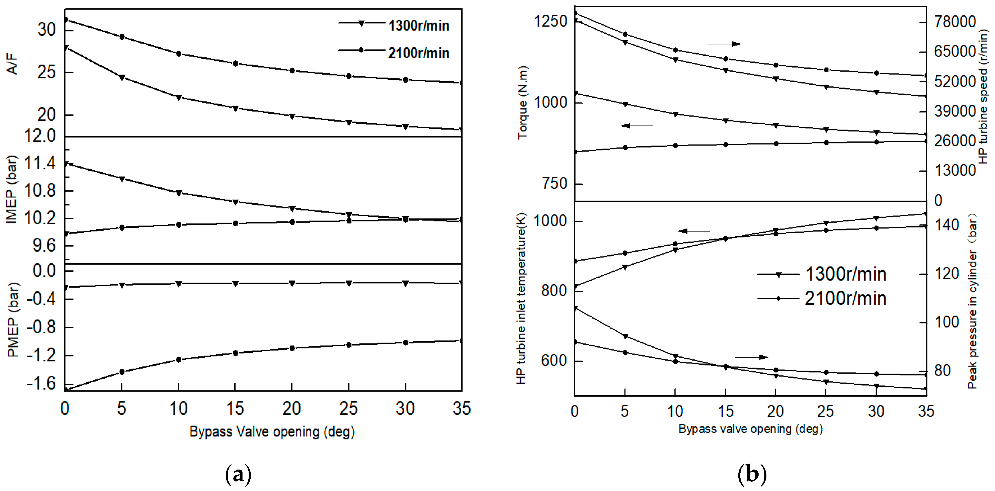
2.2. Parameter Influence Analysis
It is generally known that engine power (P), exhaust temperature, and peak pressure in a cylinder (pmax) will increase as mfuel increases. The combustion process will move forward when injection is advanced, which leads to energy reduction of exhaust gas and a rise in pmax. This has been found previously in [9,19].
The simulation goes on to explore the effects of the HP turbine bypass valve opening (θ). Figure 3a shows the simulation results of 1300 and 2100 r/min@120 mg at a 4500 m altitude. With an increase of θ, HP turbine inlet temperature (Tex) increases while pmax and the rotation speed of the HP turbocharger (nhtc) decrease. In addition, the torque curve of 1300 r/min@120 mg appears to increase while that of 2100 r/min@120 mg appears to decrease.
Figure 3.
The influence of bypass valve opening. (a) on peak pressure in a cylinder (pmax), HP turbine inlet temperature (Tex), and rotation speed of the HP turbocharger (nhtc); (b) on air fuel ratio (AFR), indicated mean effective pressure (IMEP), and pump mean effective pressure (PMEP).
As the turbine bypass valve opening increases, the air fuel ratio (AFR) and pump mean effective pressure (PMEP) both decline. The decline in AFR leads to indicated mean effective pressure (IMEP) decline. As shown in Figure 3b, at the operation point of 1300 r/min@120 mg, the decrease rate of PMEP is faster than that of IMEP, so the torque increases. At the operation point of 2100 r/min@120 mg, the decrease rate of IMEP is faster than that of PMEP, so the torque decreases.
Based on the analysis above, mfuel, fuel injection advance angle, and θ have different impacts on engine performance. It is possible to improve engine power at plateau by adjusting these parameters. Due to interactions between these parameters, it is very hard to establish the proper combination of parameters. Constraints such as pmax, Tex, and nhtc should also be satisfied. That is why the fuzzy optimization method is adopted to complete this task in the next section.
3. Design of Fuzzy Optimization Algorithm
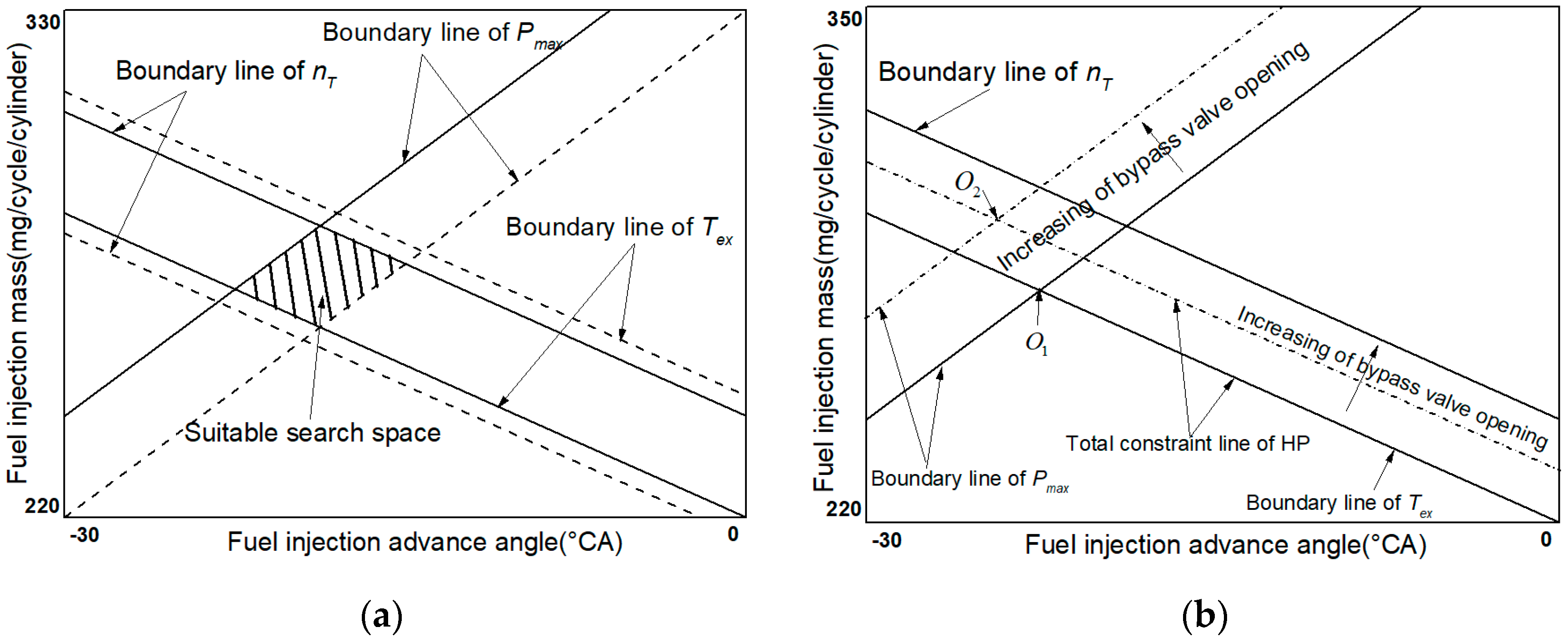
3.1. Definition of Optimization Problem
3.1.1. Optimization Aim
As stated above, the optimization aims of this paper are to find out the best combination of mfuel, fuel injection advance angle, and θ, to maximize engine power, and satisfy the boundary in Equations (1)–(3). One thing to note is that the surge of the two-stage turbocharging system and the super speed of the low-pressure stage (LP) turbine are not considered in this paper.
where is a three-dimensional vector representing the parameters to be optimized. The sub-vectors of are , , and , which correspond to mfuel, fuel injection advance angle, and θ respectively; , , and represent pmax, Tex, and nhtc respectively.
3.1.2. Boundary Transformation
In order to show how far the constraint quantities deviate from their limiting values in a unified way, the boundary terms including , , and are transformed into ‘violation degrees’ [20] as can be seen from Equations (4)–(7).
where , , and represent the violation degrees of pmax, Tex, and nhtc respectively; represents the HP turbine related parameter. When is greater than one, the exhaust energy is too rich and Tex and nhtc may exceed their limits.
3.2. Fuzzy Optimization Algorithm (FLA)
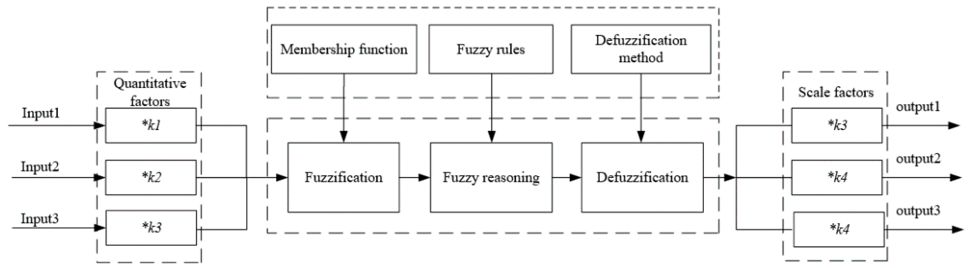
3.2.1. Algorithm Structure
The fuzzy optimization algorithm (FLA) is designed based on a fuzzy logic controller, and Figure 4 shows its structure. The input parameters include pmax, Tex, and nhtc, and the output parameters include mfuel, fuel injection advance angle, and θ.
Figure 4.
Structure of fuzzy optimization algorithm (FLA).
3.2.2. Decoupling of FLA
For a three-input three-output FLA, if the number of input lingual variables is n, there may be n3 fuzzy rules. It will be hard to define the fuzzy rules because they may be duplicated or omitted, so it is necessary to realize input-output decoupling.
Figure 5a shows constraint relationships between the input and output parameters. There are two constrained boundary lines of pmax (or Tex and nhtc). The solid and dashed lines denote the relationship between mfuel and fuel injection advance angle when pmax (or Tex and nhtc) reaches its maximum and θ is in fully open and fully closed positions respectively. When θ changes from the fully open position to the fully closed position, the pmax (or Tex and nhtc) constraint line varies from the dashed line to the solid line. The shaded area is the suitable search space.
Figure 5.
Decoupling process of FLA. (a) Constraint relationships; (b) Decoupling process.
For any one of the allowed values of θ, the constraint lines can be simplified as shown in Figure 5b. Since the Tex constraint line has the same varying trend as the nhtc constraint line, these two constraint lines can be simplified as the total constraint line of the HP turbine, which can be seen from Figure 5b. The optimal point under a certain valve opening can then be determined as O1. As θ has the opposite effect on Tex and nhtc, the total constraint line of the HP turbine can be adjusted by changing θ, and the pmax constraint line will move along with the changing value of θ. Finally, the local optimum point O1 gradually converges to the global optimum point O2 as shown in Figure 5b.
According to the analysis above, the three-input three-output FLA can be decoupled as two two-input two-output FLAs, namely a fuel FLA and an air FLA as shown in Figure 6, where , , , and represent the quantized data of , , , and respectively, and can be expressed in Equations (8)–(11); , , and represent the variations of mfuel, fuel injection advance angle, and θ respectively, and can be expressed in Equations (12)–(14); , , and are the outputs of the FLA after defuzzification; and are quantitative factors; and , , and are scale factors.

Figure 6.
Two-input two-output FLA. (a) Fuel FLA; (b) air FLA.
The air FLA will work if it satisfies the two conditions below, otherwise the fuel FLA will work:
- (1)
- and ;
- (2)
- or .
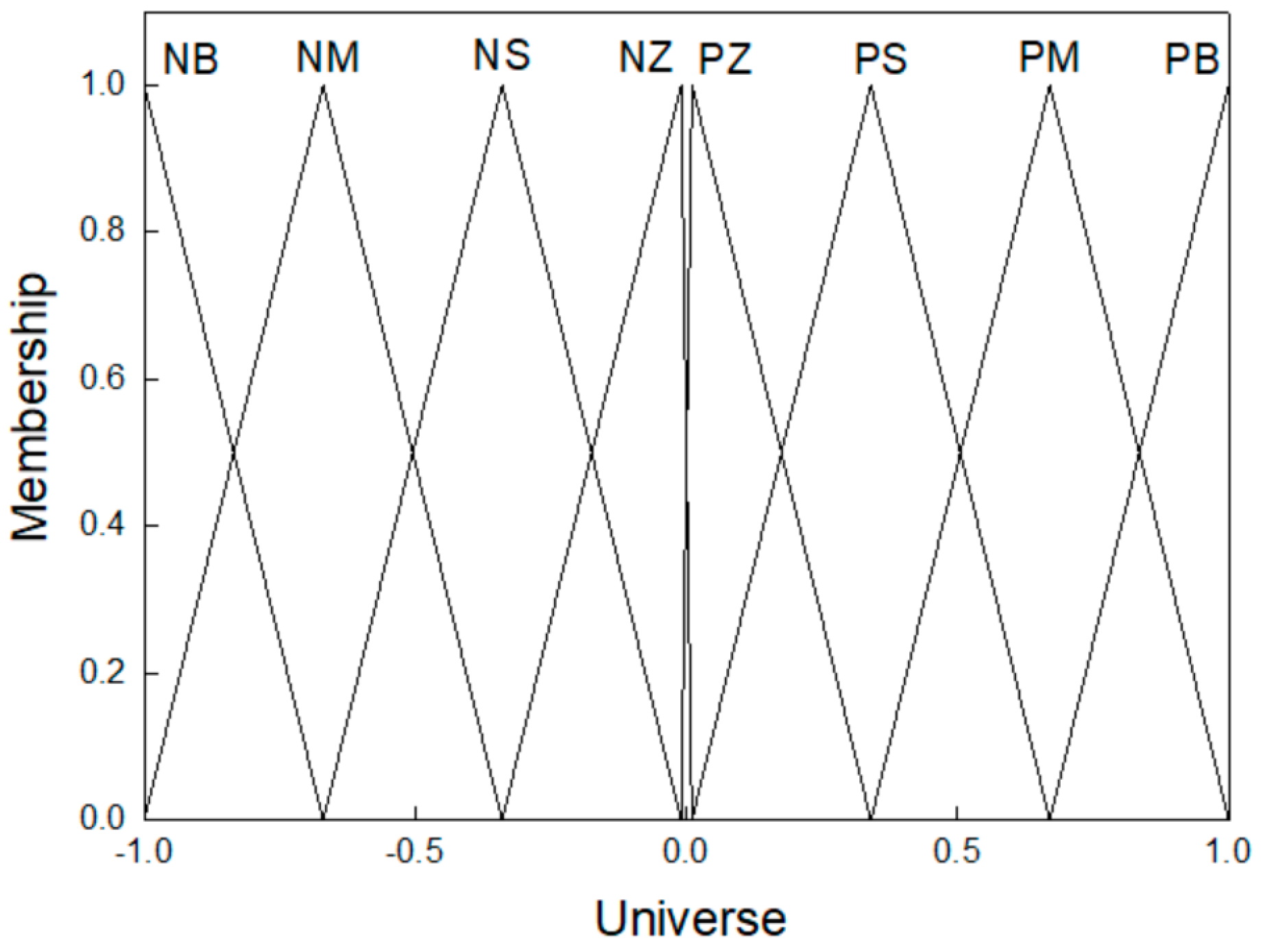
3.3. Fuzzification and Defuzzification
Fuzzification is the process of decomposing a system input and/or output into one or more fuzzy sets [21]. Many types of curve can be used, but triangular or trapezoidal membership functions are the most common [21]. In this paper, triangular membership functions are used for fuzzification processes of the input and output. Definitions of the fuzzy set are shown in Figure 7.
Figure 7.
Fuzzy set definitions.
Defuzzification is an inverse transformation which maps the output from the fuzzy domain back into the crisp domain [21]. The C-o-A method is often referred to as the Center-of-Gravity method because it computes the centroid of the composite area representing the output fuzzy term [21]. It is used for defuzzification in this paper.
3.4. Converge Conditions and Optimization Realizing
3.4.1. Convergence Conditions
If the calculation results meet any of the conditions for six consecutive times, fuzzy optimization is considered to be converged:
- (1)
- and and ;
- (2)
- { and } or { and };
- (3)
- { or or } and .
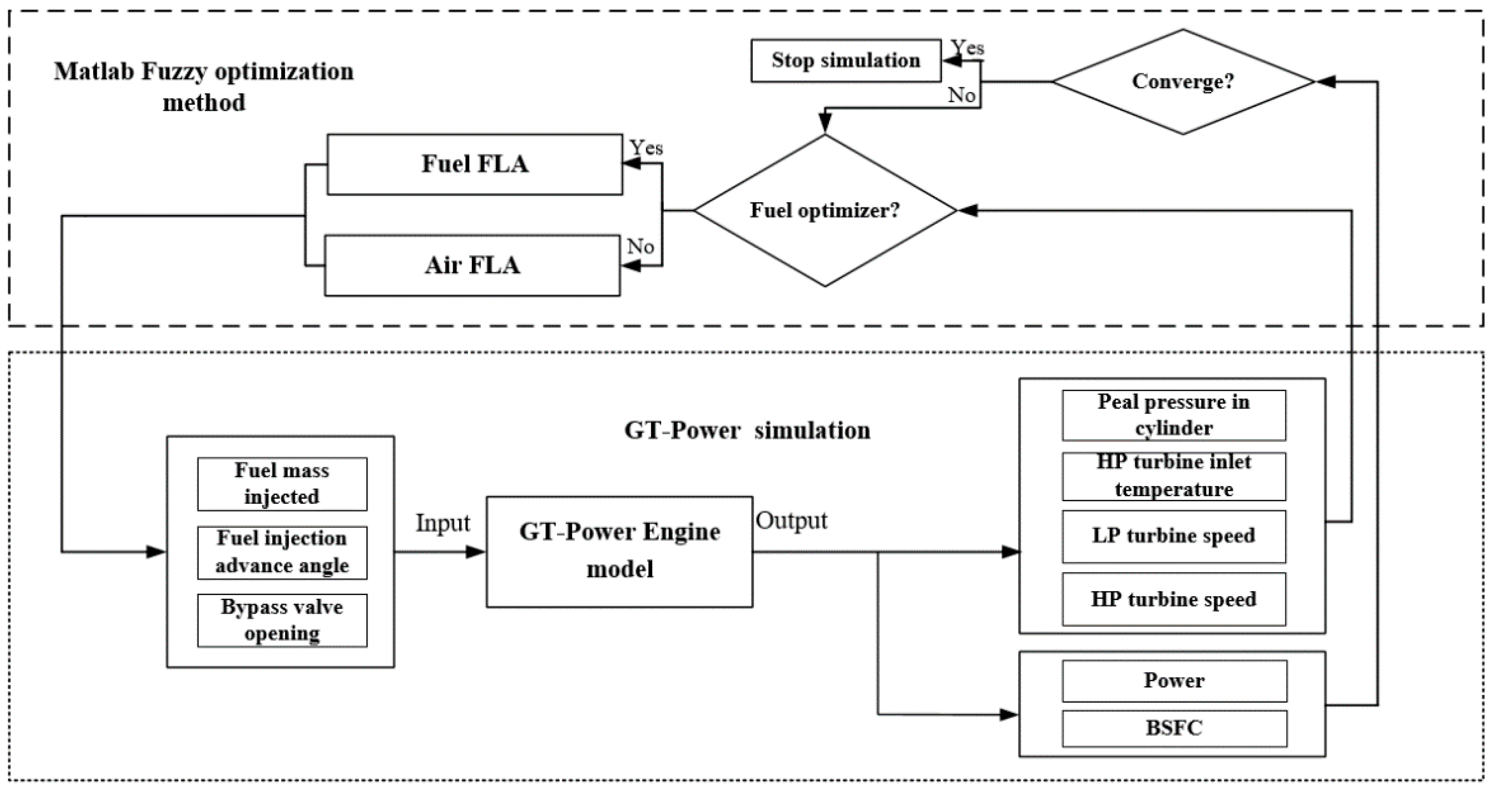
3.4.2. Realization of the Optimization
The engine model is established by GT-SUITE and co-simulated with MATLAB/Simulink. As shown in Figure 8, the joint simulation process is controlled by Simulink. Simulation data are first passed from MATLAB to GT-SUITE. Second, the GT-SUITE engine model is run and simulation results are passed to MATLAB when the GT-SUITE simulation is finished. Finally, three convergence conditions are calculated using GT-SUITE simulation data. Optimization processes continue until at least one of the three convergence conditions is met.
Figure 8.
Co-simulation model.
4. Discussion
In this section, the three adjustable parameters are optimized via co-simulation based on GT-SUITE and MATLAB/simulink platforms. Simulation results at a full load point of 2100 r/min are used as an example to show the fuzzy optimization process.
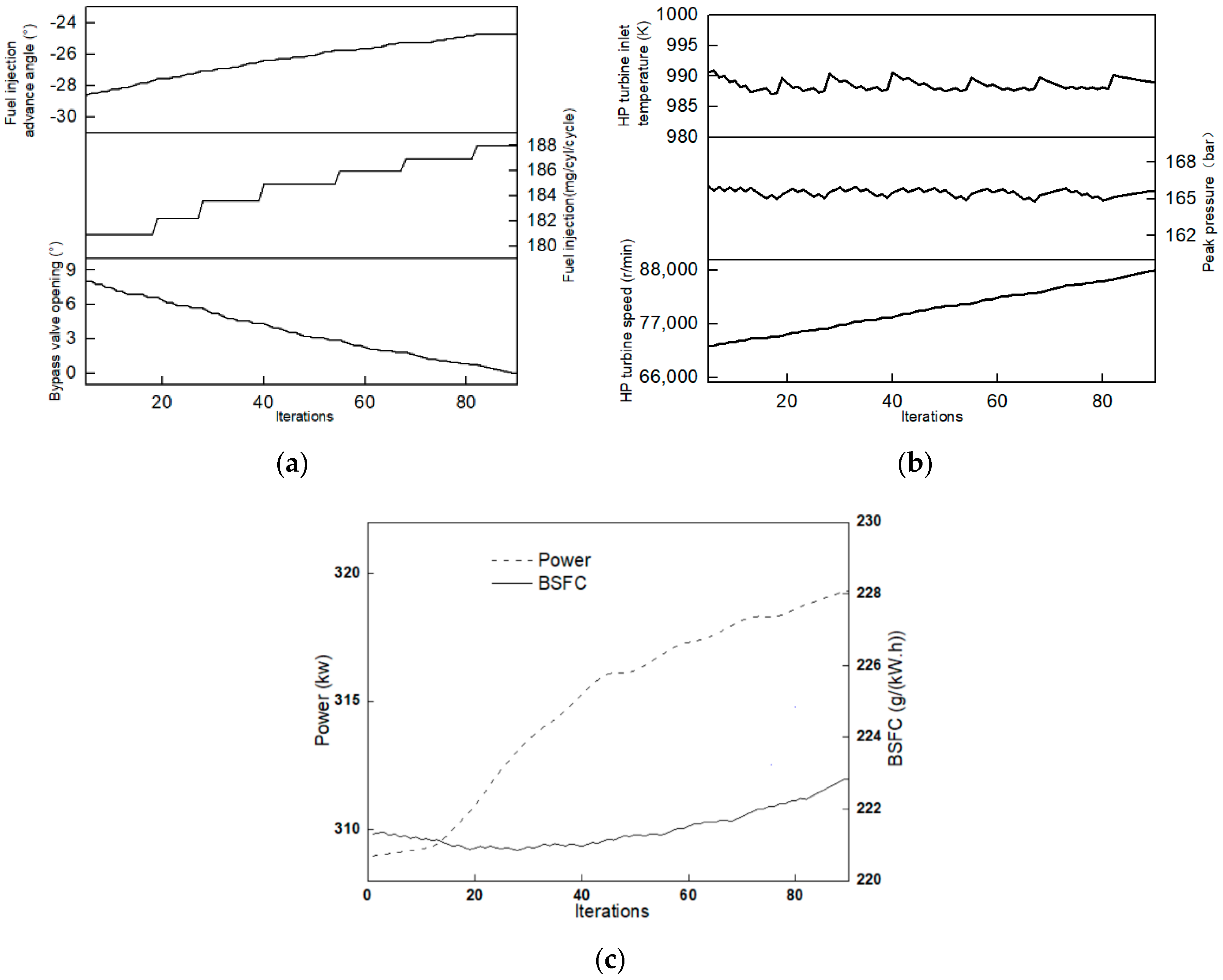
4.1. Fuzzy Optimization Process
If the calculation results meet any of the conditions for six consecutive times, fuzzy optimization is considered to be converged. Figure 9 shows the fuzzy optimization process of the full load point at 2100 r/min. During the initial phase, Tex and pmax reach their limit, but there is still space for adjustment of nhtc (see Figure 9b). Thus, the air FLA is chosen to reduce θ, which leads to the rise of pmax, and then the fuel FLA strategy starts to work to increase the fuel injection advance angle (see Figure 9a). The process is repeated until an optimal point emerges. Figure 9c shows engine output power and BSFC during the optimization process.
Figure 9.
Optimization process at full load point of 2100 r/min. (a) Optimization parameters; (b) Boundaries; (c) Engine Power and BSFC.
It can be seen that during the whole process, Tex and pmax are always kept near the limit level, and nhtc is gradually attracted to the limit level. The value of mfuel increases and the fuel injection advance angle reduces. Finally, the simulation stops when θ matches convergence condition 2.
4.2. Optimization at Full Load Conditions under 4500 m Altitude
Simulation was carried out on the co-simulation platform under full load conditions at 4500 m altitude. Table 2 shows pmax, Tex, and nhtc at each optimal point. pmax and Tex approximately reached the limit level, while there remains a little allowance for nhtc, indicating that the optimized process is reasonable.
Table 2.
Boundaries after optimization.
Figure 10a illustrates the comparison of mfuel, fuel injection advance angle, and θ before and after optimization. At low and high engine speeds, θ increases to reduce PMEP and pmax. At low to high engine speeds, the valve opening decreases to reduce Tex. After optimization, more fuel is allowed to inject into the cylinder, and the fuel injection timing can be much earlier at mid and high engine speeds.
Figure 10.
Comparison before and after optimization. (a) Adjustable parameters; (b) engine performance.
The optimized engine performance parameters including brake power, brake torque, and BSFC are compared with those of the original engine in Figure 10b. It is clear that these three performance parameters have been improved significantly. Maximum brake power was increased from 256.5 to 319.6 kW. The maximum torque was also increased from 1944.8 to 2173.2 N·m. When the engine speed is larger than 1500 r/min, BSFC declines significantly and has a maximum decrement of 9% at a full load condition of 2100 r/min.
5. Conclusions
In this paper, a simulation model of a two-stage turbocharged diesel engine is built based on experimental data. The influence of three adjustable parameters including mfuel, fuel injection advance angle, and θ is analyzed. A model-based optimization method is then used to find out the optimal combination of these three adjustable parameters. The main points of this paper can be summarized as follows.
An approach that enables joint-optimization of fuel and air supply parameters is proposed to enhance engine performance at high altitude.
The basic principles of a fuzzy logic controller are used to solve multi-objective optimization problems. When the optimal solution is located at the intersection of multiple boundaries, it may be an effective method to solve the multi constrained parameter optimization problem and to reduce the work required for parameter calibration. One thing to note is that, to simplify the definition of fuzzy rules, the number of inputs and outputs should be reduced, and in this paper the three-input three-output fuzzy logic optimizer is decoupled into two two-input two-output fuzzy logic optimizers.
Simulation results show that when the fuzzy logic optimization method is used, all performance values are improved. At the full load point of 2100 r/min, engine power increases from 256.5 to 319.6 kW, and BSFC reduces from 243.1 to 222.3 g/(kW·h). Maximum torque also increases from 1944.8 to 2173.2 N·m.
Author Contributions
Conceptualization, M.X. and F.Z.; Methodology, M.X. and F.Z.; Software, M.X.; Validation, M.X.; Formal Analysis, M.X. and F.Z.; Investigation, M.X.; Resources, M.X.; Data Curation, M.X.; Writing—Original Draft Preparation, M.X.; Writing—Review & Editing, M.X.; Visualization, M.X.; Supervision, M.X.; Project Administration, College of transportation. All authors have read and agreed to the published version of the manuscript.
Funding
This research received no external funding.
Conflicts of Interest
The authors declare no conflict of interest.
Nomenclature
| nhtc | Rotation speed of HP turbocharger (r/min) |
| pin | Intake pressure (bar) |
| α | Fuel injection advanced angle (°CA) |
| AFR | Air fuel ratio |
| n | Engine speed |
| P | Engine output power (kW) |
| θ | Bypass valve opening (deg) |
| mfuel | Fuel injection mass per cylinder per cycle (mg/cycle/cylinder) |
| Tex | HP turbine inlet temperature (K) |
| pmax | Peak pressure in cylinder (bar) |
| 0-D | Zero dimension |
| NN | Neural network |
| BSFC | Brake specific fuel consumption |
| HP | High-pressure stage |
| LP | Low-pressure stage |
| PMEP | Pump mean effective pressure |
| IMEP | Indicated mean effective pressure |
References
- Liu, S.; Shen, L.; Bi, Y.; Lei, J. Effects of altitude and fuel oxygen content on the performance of a high pressure common rail diesel engine. Fuel 2014, 118, 243–249. [Google Scholar] [CrossRef]
- Shen, L.Z.; Shen, Y.G.; Yan, W.S.; Xu, J.D. Combustion Process of Diesel Engines at Regions with Different Altitude (No. 950857); SAE Paper; SAE International: Warrendale, PA, USA, 1995. [Google Scholar]
- Shen, L.Z.; Yang, Y.Z.; Lei, J.L.; Bi, Y.H.; Yan, W.S.; Yang, Y.J. Study of performance and emissions of a turbocharged inter-cooling diesel engine at different altitudes. Trans. CSICE 2006, 24, 250–255. [Google Scholar]
- Rodgers, C. Turbocharging a high altitude UAV C. I. engine. In Proceedings of the AIAA/ASME/SAE/ASEE Joint Propulsion Conference and Exhibit, AIAA-2001-3970, Salt Lake City, UT, USA, 8–11 July 2001. [Google Scholar]
- Xin, S.; Li, W.-X. Simulation on Plateau Performance of Diesel Engine Matched with Two-stage Sequential Turbocharging System. Acta Armamentarii 2011, 32, 397–402. [Google Scholar]
- Li, H.; Zhang, G.; Zhang, H.; Shi, L.; Yang, M.; Deng, K. Equivalent matching model of a regulated two-stage turbocharging system for the plateau adaptability. Proc. Inst. Mech. Eng. Part D J. Automob. Eng. 2015, 230, 1654–1669. [Google Scholar] [CrossRef]
- Changlu, Z.; Changjiang, L.; Kai, H.; Meng, X. Regulated method based on fuel economy for regulated two-stage turbocharging system of diesel at different altitudes. Trans. Chin. Soc. Agric. Mach. 2016, 47, 369–376. [Google Scholar]
- Liu, X.H.; Wei, M.S.; Ma, C.C.; Shi, X. Simulation on one-stage and two-stage turbocharged diesel engines at different altitudes. Trans. CSICE 2010, 28, 447–452. [Google Scholar]
- Zhu, Z.X.; Zhang, F.J.; Han, K.; Liu, Y.Y.; Luo, G.L.; Li, Y.-L. Adaption of fuel injection parameters for turbocharged diesel engines working at high altitude. Binggong Xuebao/Acta Armamentarii 2014, 35, 583–589. [Google Scholar]
- Zhou, G.M.; Liu, R.L.; Dong, S.R.; Li, J.; Wang, W.; Zhong, Z.; Ge, F. Combustion Characteristics of Common Rail Diesel Engine under High Altitude (Low Pressure) Conditions. Neiranji Xuebao/Trans. CSICE 2012, 30, 220–226. [Google Scholar]
- Haikun, S.; Changlong, D.; Jianfeng, H.; Feng, F.; Ping, L.; Miandun, H.; Liang, X. Research on Compression Ratio and Fuel Injection Advance Angle Optimization of Two-stage Turbocharged Diesel engine. Binggong Xuebao/Acta Armamentarii 2017, 38, 20–26. [Google Scholar]
- Ganapathy, T.; Murugesan, K.; Gakkhar, R.P. Performance optimization of Jatropha biodiesel engine model using Taguchi approach. Appl. Energy 2009, 86, 2476–2486. [Google Scholar] [CrossRef]
- Zhao, J.; Xu, M. Fuel economy optimization of an Atkinson cycle engine using genetic algorithm. Appl. Energy 2013, 105, 335–348. [Google Scholar] [CrossRef]
- Beccari, S.; Pipitone, E.; Cammalleri, M.; Genchi, G. Model-based optimization of injection strategies for SI engine gas injectors. J. Mech. Sci. Technol. 2014, 28, 3311–3323. [Google Scholar] [CrossRef]
- Mariani, F.; Grimaldi, C.N.; Battistoni, M. Diesel engine NOx emissions control: An advanced method for the O2, evaluation in the intake flow. Appl. Energy 2014, 113, 576–588. [Google Scholar] [CrossRef]
- Ogaji, S.O.T.; Marinai, L.; Sampath, S.; Singh, R.; Prober, S.D. Gas-turbine fault diagnostics: A fuzzy-logic approach. Appl. Energy 2005, 82, 81–89. [Google Scholar] [CrossRef]
- Al-Hinti, I.; Samhouri, M.; Al-Ghandoor, A.; Sakhrieh, A. The effect of boost pressure on the performance characteristics of a diesel engine: A neuro-fuzzy approach. Appl. Energy 2009, 86, 113–121. [Google Scholar] [CrossRef]
- Zhu, Z.X.; Zhang, F.J.; Wu, T.T. Zero-D predictable combustion model based on neural network and modeling. Trans. CSICE 2015, 33, 163–170. [Google Scholar]
- Zhu, Z.; Zhang, F.; Li, C.; Wu, T.; Han, K.; Lv, J.; Li, Y.; Xiao, X. Genetic algorithm optimization applied to the fuel supply parameters of diesel engines working at plateau. Appl. Energy 2015, 157, 789–797. [Google Scholar] [CrossRef]
- Fletcher, R. An ideal penalty function for constrained optimization 1. Nonlinear Program. 1975, 15, 319–342. [Google Scholar] [CrossRef]
- Driankov, D.; Hellendoorn, H.; Reinfrank, M. An Introduction to Fuzzy Logic Control; DBLP: Zurich, Switzerland, 1996; pp. 1–5. [Google Scholar]
© 2020 by the authors. Licensee MDPI, Basel, Switzerland. This article is an open access article distributed under the terms and conditions of the Creative Commons Attribution (CC BY) license (http://creativecommons.org/licenses/by/4.0/).