Facilitating the Transition to an Inverter Dominated Power System: Experimental Evaluation of a Non-Intrusive Add-On Predictive Controller


Abstract
1. Introduction
- The choice of predictor for a given application has not been discussed.
- The fundamental hypothesis of SPAACE, i.e., the feasibility of its incorporation without requiring access to an internal controller, has not been verified. One reported experimental evaluation of SPAACE was limited to the implementation of SPAACE within the development environment of an inverter controller itself [45].
- SPAACE is a generic approach with wide application potential, yet its adoption and deployment are limited due to a lack of established evidence of its practical feasibility for real-world applications.
- The practical feasibility and robustness of SPAACE have been established utilizing a high fidelity hardware-in-the-loop systems level test bed. Conventional approaches to DER validation, commonly undertaken as equipment testing [50], are unable to de-risk the performance of the control when connected to an unknown and continuously changing system. The systems level test bed, with its reproduction of close to real-world environments, enabled the rigorous validation of SPAACE, endowing high confidence in its performance.
- For the DER controller application under consideration, a comprehensive evaluation with a set of practical variations is undertaken, i.e., analysis of choice of predictors, implementations (within and outwith the DER inherent controller), expected modes of operation and subject to a selected range of day to day operational scenarios.
- The methodological approach to ascertain computational and dynamic performance, and the subsequent detailed quantitative analysis, form the basis for the observations and recommendations reported. These are intended to serve as a reference guide for potential future users of the approach.
2. Predictive Set Point Modulation
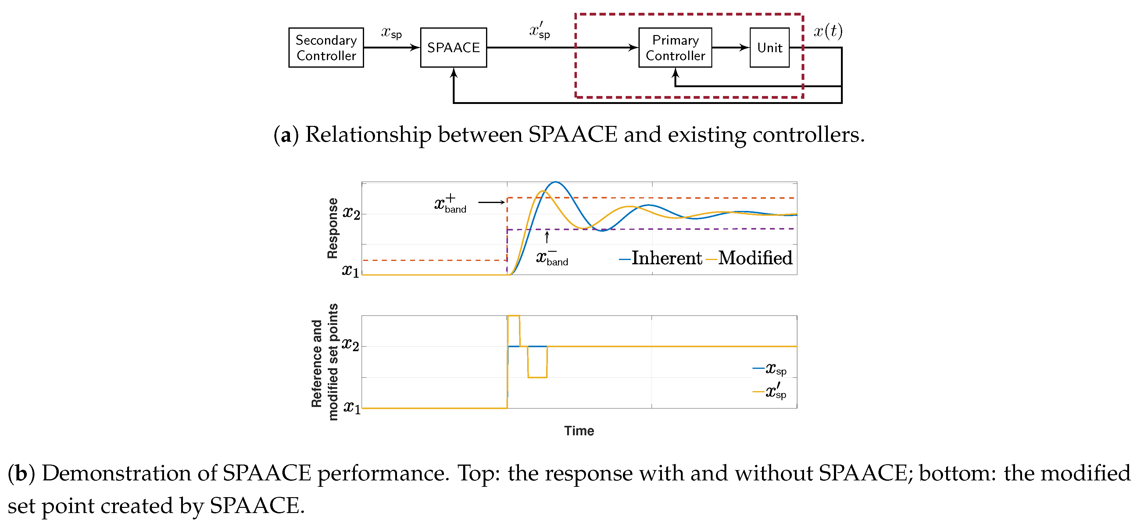
2.1. Fundamentals of Space
2.1.1. Theoretical Foundation
2.1.2. Prediction Strategies
- (a)
- Linear prediction: Linear prediction, arguably the simplest predictor, uses the following fitting function:where is the average rate of change calculated over the historical data based on LSE. With only one historical data point, linear prediction essentially results in the current value of being equal to the average of the historical data point and the predicted term:
- (b)
- Quadratic prediction: In quadratic prediction, two parameters need to be calculated based on LSE:where is as defined previously and is a measure of the second derivative of historical data—both calculated based on the LSE formulation.
- (c)
- Exponential prediction: Exponential prediction assumes that in the short-term, the response of the controlled system can be approximated as an exponential rise or decay. Consequently, it fits an exponential function to the historical data aswhere a and b are calculated based on LSE.
2.2. Implementation Considerations
2.2.1. Parameter Selection
- (a)
- Scaling factor: Selecting a smaller m creates modified set points that are closer to the original set point and thus changes to the set point are smaller and smoother. In contrast, a larger m introduces more severe set point changes that can help with achieving faster damping. In most cases, a modest value of seems to produce reasonably fast results. A more detailed discussion of the effect of m on the system performance is presented in [47,49]; an analytical discussion is presented in [46].
- (b)
- Prediction strategy and prediction horizon: Several parameters can affect the accuracy of the prediction. In addition to the nature of the system response which suggests the type of fitting function (prediction strategy), prediction horizon , and window of prediction history are important design parameters. In general, should correspond to the inverse of the system dominant natural frequency . That is, a faster system needs a smaller and vice versa. Heuristically, an acceptable rule of thumb is to choose .
- (c)
- Tolerance band: Typically the band is chosen to be symmetrical around the set point, but this is not a requirement for SPAACE operation, rather a design preference.
2.2.2. Real-World Implications
- (a)
- Feasibility: Most real-world systems are non-linear in nature, for which linear (taking advantage of established linearization methods) and non-linear control approaches have been widely utilized. As SPAACE is an add on controller, its incorporation is independent of the control approach (linear or non-linear) and the non-linearities within the unit under consideration. Therefore, in theory, SPAACE can be incorporated within a unit under consideration for any application where precise and high-speed set point tracking is imperative. By enabling the unit under consideration to be treated effectively as a black box, SPAACE can increase the potential utilization of the existing infrastructure by reducing transients, which in turn reduces the need to overdesign the system.Furthermore, the stability of SPAACE was discussed in [46]. It was shown that the incorporation of SPAACE within an apparatus does not impact the stability of the wider system, i.e., if the system with the apparatus was stable without SPAACE, it will remain stable with the incorporation of SPAACE. Therefore, SPAACE can readily be adopted within power system applications, ranging from small isolated systems such as electric propulsion applications to larger systems such as HVDC segmented power systems.This paper, in particular, discusses the incorporation of SPAACE in DERs coupled to the remainder of the power system via power electronic interfaces (inverters or converters). This choice is motivated by the current practices and challenges faced by the community: transition to a renewable rich inverter-dominated grid (utility systems), interest in incorporation within small-scale systems with variable and flexible architectures (remote microgrids and propulsion applications), to name a few. Furthermore, it provides a more relevant example for demonstration as DER manufacturer’s practices historically present limitations in access to the internal parameters of the inverter and the unavailability of the system model with inverters.
- (b)
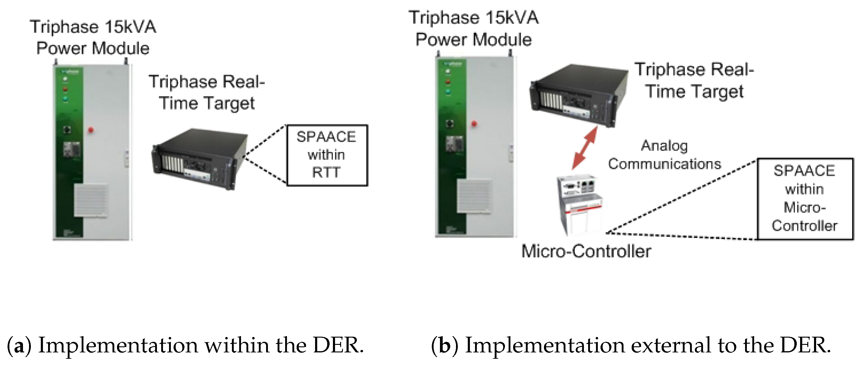
- Architecture and Communications: SPAACE is designed for incorporation within an individual apparatus with a view to improving its dynamic response. SPAACE does not require any additional information outwith the apparatus, and therefore no communication is required. From an architectural perspective, the implementation of SPAACE can be referred to as decentralized. Depending on whether SPAACE is incorporated within the controller of the DER or on an external controller, very short distance communications via analog connection may be present.
- (c)
- Responsibility: The responsibility to incorporate SPAACE would essentially lie with the owner of the DER. An end user, such as a residential customer with a battery energy storage system (BESS) interfaced via an inverter, might not have an incentive for the incorporation of SPAACE. However, the benefits the approach brings to the wider grid system might interest distribution system operators, virtual power plant operators, or demand aggregators to provide incentives to the end user for its incorporation. Alternatively, this can be set forth as a requirement by a demand aggregator for any end user BESS unit to participate within ancillary service markets.
- (d)
- Commercialization: The details of the implementation of SPAACE and its corresponding prediction strategies have been summarized in this work. SPAACE does not exist as a commercial product, however, the entities identified above (distribution system operators, virtual power plant operators, or demand aggregators) can develop their own solutions with confidence instilled in real-world applicability through contributions of this paper.
3. Experimental Setup
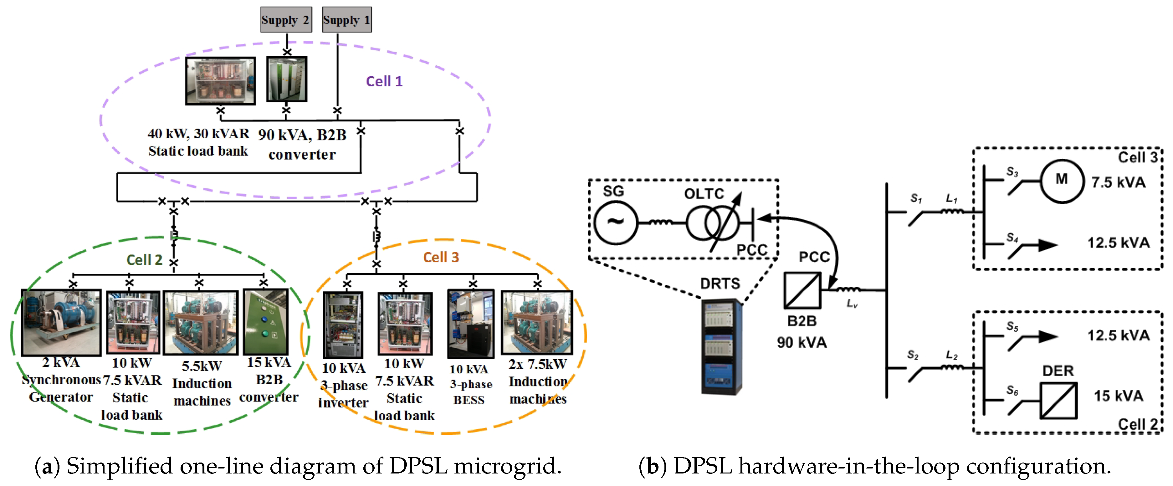
3.1. Test Rig
3.2. Test Configurations
3.2.1. Spaace within the Der Controller
3.2.2. Spaace Outwith the Der Controller
3.3. Controls for Grid-Connected and Islanded Operation
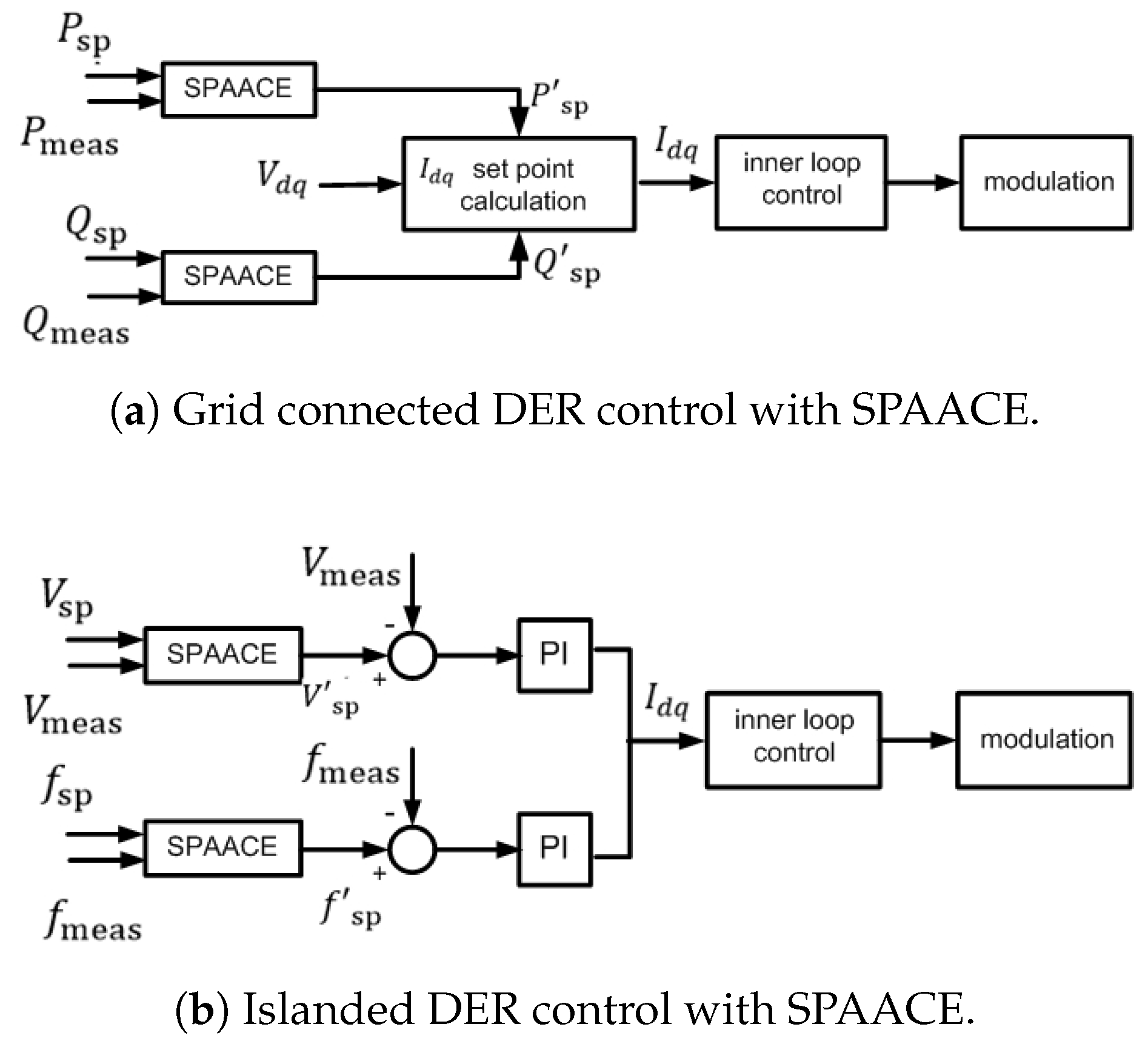
3.3.1. Grid-Connected Operation
3.3.2. Islanded Operation
4. Performance Evaluation
4.1. Methodology
4.1.1. Computational Complexity
- Execution time: This refers to the time taken for the execution of SPAACE represented by .
- Memory requirement: This refers to the memory requirement of the algorithm as represented by M.
4.1.2. Dynamic Response
- Settling time: The settling time is the time elapsed from the time of the disturbance to the time when the measured output signal stays within the defined tolerance band .
- Overshoot: Defining the maximum excursion of subject to an external disturbance or after a step change in the reference set point as , the overshoot is calculated as
- Cumulative tracking error: Cumulative tracking error is defined as the sum of the tracking errors at every time step from the application of the step or the disturbance to the time when the measured output signal has settled, i.e., .where . A smaller corresponds to better set point tracking capability.
4.2. Computational Complexity Evaluation
4.3. Dynamic Response
4.3.1. Grid-Connected Operation
- (a)
- Set point change in real power: Events 1 and 6 emulate the day to day operations of a DER where, for example, the reference real power set point of a DER is changed based on its commitment to contribute to frequency control. The response of the DER subject to a real power set point change from 2 kW to 6 kW at and from 6 kW to 2 kW at is shown in columns 1 and 6 of Figure 6a,b with the performance indicators presented in Table 4. When SPAACE is incorporated, a minimum overshoot reduction of 16.52% for set point increase and 11.25% for set point decrease is observed. For step increase in set point, a minimum of 84.4% reduction in settling time is observed while for step decrease in set point the system response did not violate the tolerance band and therefore the settling time reported as 0 s.
- (b)
- Grid voltage set point change: Events 2 and 3 represent a set of transient conditions that can be expected within a distribution grid with high penetration of solar photovoltaic installations. A sudden cloud cover across a distribution feeder can lead to a drop in voltage, and the clearing of the cloud cover can lead to an increase in voltage. In this case study, the voltage magnitude is changed using the 90 kVA B2B module. The response of the DER subject to a grid voltage set point change from 1 pu to 1.1 pu at and from 1.1 pu to 1 pu at is shown in columns 2 and 3 of Figure 6a,b with the performance indicators presented in Table 4. The inherent controller employed for the grid-connected mode, in this case, works as a poorly tuned controller, for which the increase in system voltage causes oscillations in the power output. With SPAACE, the response of the system is well damped with improvement in overshoot observed.
- (c)
- Impact of system short-circuit ratio (SCR): Events 4 and 5 evaluate the dynamic performance of the DER subject to a change in system short circuit ratio (SCR). For 100% inverter-penetrated microgrids, changing the virtual impedance of individual inverters is an effective solution to improve overall system stability [61]. Changing of individual inverters in turn impacts the SCR of the system. The response of the DER to a change in virtual impedance is shown in columns 4 and 5 of Figure 6a,b, where is reduced from 50 H to 5 H at and increased back to 50 H at . The minimum improvement with SPAACE observed for overshoot reduction is 5.67%. With SPAACE, the response of the system does not violate the tolerance band , thus having a 0 s settling time.
- (d)
- Induction motor energization: Event 7 evaluates the response of the DER subject to a switching transient on the network. For the system under study, the switching transient is emulated by the energization of a 7.5 kVA induction motor. The response of the DER is shown in column 7 of Figure 6a,b. From the performance indicators presented in Table 4, it is evident that SPAACE improves the system performance with minimum overshoot reduction of 4.85% and a 7.4% reduction in settling time.
- (e)
- Cumulative tracking error: Table 4 also presents a comparison of the cumulative tracking error () for the inherent controller and the three variants of SPAACE under both implementations (within and outwith the DER). All variants of SPAACE reduce for each of the seven events under consideration under both implementations. There is no distinctive performance difference between the three variants and the two implementations.
- (f)
- Summary: In this subsection, the dynamic performance of a weak controller operating in the grid-connected mode is evaluated. For the seven events under consideration, SPAACE considerably improves the dynamic performance with respect to each of the key indicators defined. This paper shows the feasibility of the implementation of SPAACE outwith the DER. In most cases, the performance of SPAACE when implemented outwith the DER is slightly inferior to its performance when it is implemented within the DER controller. This can be attributed to the communications delay to communicate the modified set point from the microcontroller to the DER internal controller. SPAACE’s performance can be further optimized by considering the time delay during the design of the predictor.
4.3.2. Islanded Operation
5. Conclusions
- The linear predictor is computationally the most efficient with the least time and space complexity. In addition, the time and space complexity of a linear predictor does not increase with an increase in the prediction horizon.
- The choice of predictor only marginally impacts the dynamic performance and therefore, based on the computational performance evaluation, the use of a linear predictor is recommended. This is an application-specific recommendation, however, the trade-off between computational and dynamic performance should be assessed, specifically given the demonstrated close performance of linear and quadratic predictors.
- With a weak controller (in grid-connected mode), the incorporation of SPAACE leads to improvement in the dynamic properties (at least one of settling time, overshoot, and tracking error) of the response subject to the studied disturbances. With a strong controller (in islanded mode), the impact of SPAACE is limited to bringing the system to steady-state faster.
- The set of events chosen are non-exhaustive but sufficient for demonstration of the performance of the approach under a broad range of circumstances. However, given the versatility of its operation, the improvement of dynamics under unknown system conditions can be expected.
Author Contributions
Funding
Conflicts of Interest
Nomenclature
| Abbreviations | |
| SPAACE | Set point automatic adjustment with correction enabled. |
| SPM | Set point modulation. |
| DER | Distributed energy resource. |
| HIL | Hardware-in-the-loop. |
| SISO | Single input single output. |
| LSE | Least square error. |
| DPSL | Dynamic power systems laboratory. |
| B2B | Back to back. |
| RTT | Real time target. |
| SCR | Short circuit ratio. |
| HVDC | High voltage direct current. |
| BESS | Battery energy storage system. |
| DRTS | Digital real-time simulator. |
| Variables | |
| Reference set point. | |
| x | Measured output. |
| Initial reference set point. | |
| Final reference set point. | |
| Modified set point. | |
| m | Scaling factor. |
| Horizon of prediction. | |
| n | An integer value. |
| Predicted value of x. | |
| r | Average rate of change of historical data. |
| q | Second derivative of historical data. |
| Real power set point. | |
| Reactive power set point. | |
| Measured real power. | |
| Measured reactive power. | |
| Modified real power set point. | |
| Modified reactive power set point. | |
| Direct and quadrature components of voltage. | |
| Direct and quadrature components of current. | |
| Voltage set point. | |
| Frequency set point. | |
| Measured voltage. | |
| Measured frequency. | |
| Modified voltage set point. | |
| Modified frequency set point. | |
| Switches within the utilized network. | |
| Line impedances within the utilized network. | |
| Execution time. | |
| M | Memory requirement. |
| Settling time. | |
| Absolute maximum value of x. | |
| Time step. | |
| Cumulative tracking error. | |
| Overshoot. | |
| Virtual impedance. | |
| Window of prediction history. | |
| Upper threshold of tolerance band. | |
| Lower threshold of tolerance band. | |
| Tolerance band. | |
| Dominant natural frequency. |
References
- Fan, B.; Peng, J.; Yang, Q.; Liu, W. Distributed Periodic Event-Triggered Algorithm for Current Sharing and Voltage Regulation in DC Microgrids. IEEE Trans. Smart Grid 2020, 11, 577–589. [Google Scholar] [CrossRef]
- Fan, B.; Guo, S.; Peng, J.; Yang, Q.; Liu, W.; Liu, L. A Consensus-Based Algorithm for Power Sharing and Voltage Regulation in DC Microgrids. IEEE Trans. Ind. Inform. 2020, 16, 3987–3996. [Google Scholar] [CrossRef]
- Ding, D.; Han, Q.-L.; Wang, Z.; Ge, X. A Survey on Model-Based Distributed Control and Filtering for Industrial Cyber-Physical Systems. IEEE Trans. Ind. Inform. 2019, 15, 2483–2499. [Google Scholar] [CrossRef]
- Molzahn, D.K.; Dorfler, F.; Sandberg, H.; Low, S.H.; Chakrabarti, S.; Baldick, R.; Lavaei, J. A Survey of Distributed Optimization and Control Algorithms for Electric Power Systems. IEEE Trans. Smart Grid 2017, 8, 2941–2962. [Google Scholar] [CrossRef]
- Li, H.; Li, F.; Xu, Y.; Rizy, D.T.; Kueck, J.D. Adaptive Voltage Control With Distributed Energy Resources: Algorithm, Theoretical Analysis, Simulation, and Field Test Verification. IEEE Trans. Power Syst. 2010, 25, 1638–1647. [Google Scholar] [CrossRef]
- Leithead, W. Survey of Gain-Scheduling Analysis Design. Int. J. Control 1999, 73, 1001–1025. [Google Scholar] [CrossRef]
- Namara, P.M.; Negenborn, R.R.; Schutter, B.D.; Lightbody, G. Optimal Coordination of a Multiple HVDC Link System Using Centralized and Distributed Control. IEEE Trans. Control Syst. Technol. 2013, 21, 302–314. [Google Scholar] [CrossRef]
- Moradzadeh, M.; Boel, R.; Vandevelde, L. Voltage Coordination in Multi-Area Power Systems via Distributed Model Predictive Control. IEEE Trans. Power Syst. 2013, 28, 513–521. [Google Scholar] [CrossRef]
- Roshany-Yamchi, S.; Cychowski, M.; Negenborn, R.; Schutter, B.; Delaney, K.; Connell, J. Kalman Filter-Based Distributed Predictive Control of Large-Scale Multi-Rate Systems: Application to Power Networks. IEEE Trans. Control. Syst. Technol. 2013, 21, 27–39. [Google Scholar] [CrossRef]
- Liu, X.; Kong, X.; Lee, K.Y. Distributed model predictive control for load frequency control with dynamic fuzzy valve position modelling for hydro–thermal power system. IET Control Theory Appl. 2016, 10, 1653–1664. [Google Scholar] [CrossRef]
- Mehmood, F.; Khan, B.; Ali, S.M.; Rossiter, J.A. Distributed model predictive based secondary control for economic production and frequency regulation of MG. IET Control Theory Appl. 2019, 13, 2948–2958. [Google Scholar] [CrossRef]
- Åström, K.J.; Hägglund, T. PID Controllers: Theory, Design and Tuning, 2nd ed.; Instrument society of America: Research Trinangle Park, NC, USA, 1995. [Google Scholar]
- Åström, K.J. Auto-Tuning, Adaptation and Expert Control. In Proceedings of the American Control Conference, Boston, MA, USA, 19–21 June 1985; pp. 1514–1519. [Google Scholar]
- Åström, K.J.; Murray, R.M. Feedback Systems: An Introduction for Scientists and Engineers, 2nd ed.; Princeton University Press: Princeton, NJ, USA, 2008. [Google Scholar]
- Åström, K.J.; Hägglund, T. Automatic Tuning of PID Controllers. In The Control Handbook; Levin, W., Ed.; Number 53; CRC Press: Boca Raton, FL, USA, 1996. [Google Scholar]
- Killingsworth, N.; Krstic, M. PID Tuning Using Extremum Seeking: Online, model-free performance optimization. IEEE Control Syst. Mag. 2006, 26, 70–79. [Google Scholar]
- Hjalmarsson, H.; Gevers, M.; Gunnarsson, S.; Lequin, O. Iterative feedback tuning: Theory and applications. IEEE Control. Syst. 1998, 18, 26–41. [Google Scholar]
- Lequin, O.; Bosmans, E.; Triest, T. Iterative feedback tuning of PID parameters: Comparison with classical tuning rules. Contr. Eng. Pract. 2003, 11, 1023–1033. [Google Scholar] [CrossRef]
- Lequin, O.; Gevers, M.; Triest, T. Optimizing the settling time with iterative feedback tuning. In Proceedings of the 15th IFAC World Congress, Beijing, China, 5–9 July 1999; pp. 433–437. [Google Scholar]
- Burns, D.J.; Laughman, C.R.; Guay, M. Proportional–Integral Extremum Seeking for Vapor Compression Systems. IEEE Trans. Control Syst. Technol. 2020, 28, 403–412. [Google Scholar] [CrossRef]
- Hunnekens, B.; Dino, A.D.; van de Wouw, N.; van Dijk, N.; Nijmeijer, H. Extremum-Seeking Control for the Adaptive Design of Variable Gain Controllers. IEEE Trans. Control Syst. Technol. 2015, 23, 1041–1051. [Google Scholar] [CrossRef]
- Lu, X.; Krstić, M.; Chai, T.; Fu, J. Hardware-in-the-Loop Multiobjective Extremum-Seeking Control of Mineral Grinding. IEEE Trans. Control Syst. Technol. 2020, 1–11. [Google Scholar] [CrossRef]
- Smith, O.J.M. Posicast Control of Damped Oscillatory Systems. Proc. IRE 1957, 45, 1249–1255. [Google Scholar] [CrossRef]
- Hung, J.Y. Feedback Control with Posicast. IEEE Trans. Ind. Electron. 2003, 50, 94–99. [Google Scholar] [CrossRef]
- Vaughan, J.; Smith, A.; Kang, S.J.; Singhose, W. Predictive Graphical User Interface Elements to Improve Crane Operator Performance. IEEE Trans. Syst. Man Cybern. Part A Syst. Hum. 2011, 41, 323–330. [Google Scholar] [CrossRef]
- Cook, G. An Application of Half-Cycle Posicast. IEEE Trans. Autom. Control 1966, 11, 556–559. [Google Scholar] [CrossRef]
- Hung, J.Y. Posicast Control Past and Present. IEEE Multidiscip. Eng. Educ. Mag. 2007, 2, 7–11. [Google Scholar]
- Feng, Q.; Nelms, R.M.; Hung, J.Y. Posicast-Based Digital Control of the Buck Converter. IEEE Trans. Ind. Electron. 2006, 53, 759–767. [Google Scholar] [CrossRef]
- Mi, Y.; Song, Y.; Fu, Y.; Wang, C. The Adaptive Sliding Mode Reactive Power Control Strategy for Isolated Wind-Diesel Power System Based on Sliding Mode Observer. IEEE Trans. Sustain. Energy 2019. [Google Scholar] [CrossRef]
- Zhang, Y.; Li, G. Non-causal Linear Optimal Control of Wave Energy Converters with Enhanced Robustness by Sliding Mode Control. IEEE Trans. Sustain. Energy 2019. [Google Scholar] [CrossRef]
- Onyeka, A.E.; Xing-Gang, Y.; Mao, Z.; Jiang, B.; Zhang, Q.; Yan, X. Robust decentralised load frequency control for interconnected time delay power systems using sliding mode techniques. IET Control Theory Appl. 2020, 14, 470–480. [Google Scholar] [CrossRef]
- Sarkar, M.K.; Dev, A.; Asthana, P.; Narzary, D. Chattering free robust adaptive integral higher order sliding mode control for load frequency problems in multi-area power systems. IET Control Theory Appl. 2018, 12, 1216–1227. [Google Scholar] [CrossRef]
- Zhang, H.; Zhou, J.; Sun, Q.; Guerrero, J.M.; Ma, D. Data-Driven Control for Interlinked AC/DC Microgrids Via Model-Free Adaptive Control and Dual-Droop Control. IEEE Trans. Smart Grid 2017, 8, 557–571. [Google Scholar] [CrossRef]
- Safaei, A.; Mahyuddin, M.N. Adaptive Model-Free Control Based on an Ultra-Local Model With Model-Free Parameter Estimations for a Generic SISO System. IEEE Access 2018, 6, 4266–4275. [Google Scholar] [CrossRef]
- Hou, Z.; Zhu, Y. Controller-Dynamic-Linearization-Based Model Free Adaptive Control for Discrete-Time Nonlinear Systems. IEEE Trans. Ind. Inform. 2013, 9, 2301–2309. [Google Scholar] [CrossRef]
- Chen, J.; Yang, F.; Han, Q.-L. Model-Free Predictive H∞ Control for Grid-Connected Solar Power Generation Systems. IEEE Trans. Control Syst. Technol. 2014, 22, 2039–2047. [Google Scholar] [CrossRef]
- Duan, L.; Hou, Z.; Yu, X.; Jin, S.; Lu, K. Data-Driven Model-Free Adaptive Attitude Control Approach for Launch Vehicle With Virtual Reference Feedback Parameters Tuning Method. IEEE Access 2019, 7, 54106–54116. [Google Scholar] [CrossRef]
- Lu, C.; Zhao, Y.; Men, K.; Tu, L.; Han, Y. Wide-area power system stabiliser based on model-free adaptive control. IET Control Theory Appl. 2015, 9, 1996–2007. [Google Scholar] [CrossRef]
- Wang, H.; Yang, J.; Chen, Z.; Ge, W.; Li, Y.; Ma, Y.; Dong, J.; Okoye, M.O.; Yang, L.; Onyeka, O.M. Analysis and Suppression for Frequency Oscillation in a Wind-Diesel System. IEEE Access 2019, 7, 22818–22828. [Google Scholar] [CrossRef]
- Zolfaghari, M.; Hosseinian, S.H.; Fathi, S.H.; Abedi, M.; Gharehpetian, G.B.; Fathi, S.H. A New Power Management Scheme for Parallel-Connected PV Systems in Microgrids. IEEE Trans. Sustain. Energy 2018, 9, 1605–1617. [Google Scholar] [CrossRef]
- M’Zoughi, F.; Garrido, I.; Garrido, A.J.; De La Sen, M. Fuzzy Gain Scheduled-Sliding Mode Rotational Speed Control of an Oscillating Water Column. IEEE Access 2020, 8, 45853–45873. [Google Scholar] [CrossRef]
- Sun, H.; Zong, G.; Ahn, C.K. Quantized Decentralized Adaptive Neural Network PI Tracking Control for Uncertain Interconnected Nonlinear Systems With Dynamic Uncertainties. IEEE Trans. Syst. Man Cybern. Syst. 2019, 1–14. [Google Scholar] [CrossRef]
- Su, X.; Liu, Z.; Zhang, Y.; Chen, C.L.P. Event-Triggered Adaptive Fuzzy Tracking Control for Uncertain Nonlinear Systems Preceded by Unknown Prandtl-Ishlinskii Hysteresis. IEEE Trans. Cybern. 2019, 1–14. [Google Scholar] [CrossRef]
- Mehrizi-Sani, A.; Iravani, R. Online Set Point Adjustment for Trajectory Shaping in Microgrid Applications. IEEE Trans. Power Syst. 2012, 27, 216–223. [Google Scholar] [CrossRef]
- Yazdanian, M.; Mehrizi-Sani, A.; Seebacher, R.; Krischan, K.; Muetze, A. Smooth reference modulation to improve dynamic response in drive systems. IEEE Trans. Power Electron. 2018, 33, 6434–6443. [Google Scholar] [CrossRef]
- Mehrizi-Sani, A.; Iravani, R. Online Set Point Modulation to Enhance Microgrid Dynamic Response: Theoretical Foundation. IEEE Trans. Power Syst. 2012, 27, 2167–2174. [Google Scholar] [CrossRef]
- Ghaffarzadeh, H.; Stone, C.; Mehrizi-Sani, A. Predictive set point modulation to mitigate transients in lightly damped balanced and unbalanced systems. IEEE Trans. Power Syst. 2016, 32, 1041–1049. [Google Scholar] [CrossRef]
- Ghaffarzadeh, H.; Mehrizi-Sani, A. Predictive set point modulation to mitigate transients in power systems with a multiple-input-multiple-output control system. In Proceedings of the IEEE Innovative Smart Grid Technologies Conference (ISGT), Minneapolis, MN, USA, 6–9 September 2016. [Google Scholar]
- Mehrizi-Sani, A.; Iravani, R. Performance Evaluation of a Distributed Control Scheme for Overvoltage Mitigation. In Proceedings of the CIGRÉ International Symposium on The Electric Power System of The Future: Integrating supergrids and microgrids, Bologna, Italy, 13–15 September 2011. [Google Scholar]
- Sandia National Laboratories. Test Protocols for Advances Inverter Interoperability Functions; Sandia Corporation: Albuquerque, NM, USA, 2013; pp. 1–22.
- Guillo-Sansano, E.; Syed, M.H.; Roscoe, A.J.; Burt, G.M. Initialization and Synchronization of Power Hardware-In-The-Loop Simulations: A Great Britain Network Case Study. Energies 2018, 11, 1087. [Google Scholar] [CrossRef]
- Guillo-Sansano, E.; Syed, M.H.; Roscoe, A.J.; Burt, G.M.; Coffele, F. Characterization of Time Delay in Power Hardware in the Loop Setups. IEEE Trans. Ind. Electron. 2020, 50, 1–10. [Google Scholar] [CrossRef]
- Blair, S.M.; Syed, M.H.; Roscoe, A.J.; Burt, G.M.; Braun, J. Measurement and Analysis of PMU Reporting Latency for Smart Grid Protection and Control Applications. IEEE Access 2019, 7, 48689–48698. [Google Scholar] [CrossRef]
- Guillo-Sansano, E.; Roscoe, A.J.; Burt, G.M. Harmonic-by-harmonic time delay compensation method for PHIL simulation of low impedance power systems. In Proceedings of the 2015 International Symposium on Smart Electric Distribution Systems and Technologies (EDST), Vienna, Austria, 8–11 September 2015; pp. 560–565. [Google Scholar] [CrossRef]
- Li, Q.; Yu, S.; Al-Sumaiti, A.; Turitsyn, K. Modeling and Co-Optimization of a Micro Water-Energy Nexus for Smart Communities. In Proceedings of the 2018 IEEE PES Innovative Smart Grid Technologies Conference Europe (ISGT-Europe), Sarajevo, Bosnia-Herzegovina, 21–25 October 2018; pp. 1–5. [Google Scholar]
- Hao, H.; Somani, A.; Lian, J.; Carroll, T.E. Generalized aggregation and coordination of residential loads in a smart community. In Proceedings of the 2015 IEEE International Conference on Smart Grid Communications (SmartGridComm), Miami, FL, USA, 2–5 November 2015; pp. 67–72. [Google Scholar]
- Syed, M.H.; Guillo-Sansano, E.; Avras, A.; Downie, A.; Jennett, K.; Burt, G.M.; Coffele, F.; Rudd, A.; Bright, C. The Role of Experimental Test Beds for the Systems Testing of Future Marine Electrical Power Systems. In Proceedings of the 2019 IEEE Electric Ship Technologies Symposium (ESTS), Washington, DC, USA, 14–16 August 2019; pp. 141–148. [Google Scholar]
- Kontis, E.O.; Nousdilis, A.I.; Papagiannis, G.K.; Syed, M.H.; Guillo-Sansano, E.; Burt, G.; Papadopoulos, T.A. Power Hardware-in-the-Loop Setup for Developing, Analyzing and Testing Mode Identification Techniques and Dynamic Equivalent Models. In Proceedings of the 2019 IEEE Milan PowerTech, Milan, Italy, 23–27 June 2019; pp. 1–6. [Google Scholar]
- Syed, M.H.; Sansano, E.G.; Blair, S.M.; Burt, G.; Prostejovsky, A.M.; Rikos, E. Enhanced load frequency control: Incorporating locational information for temporal enhancement. IET Gener. Transm. Distrib. 2019, 13, 1865–1874. [Google Scholar] [CrossRef]
- Wang, Y.; Syed, M.H.; Guillo-Sansano, E.; Xu, Y.; Burt, G.M. Inverter-Based Voltage Control of Distribution Networks: A Three-Level Coordinated Method and Power Hardware-in-the-Loop Validation. IEEE Trans. Sustain. Energy 2019. [Google Scholar] [CrossRef]
- Lu, X.; Sun, K.; Guerrero, J.M.; Vasquez, J.C.; Huang, L.; Wang, J. Stability Enhancement Based on Virtual Impedance for DC Microgrids With Constant Power Loads. IEEE Trans. Smart Grid 2015, 6, 2770–2783. [Google Scholar] [CrossRef]


| Approach | References | No Model | Noninternal |
|---|---|---|---|
| PI gain scaling | [5,6] | ✓ | X |
| Set point ramping | ✓ | ✓ | |
| Model predictive control | [7,8,9,10,11] | X | X |
| Adding a D-term to PI | [12,13,14] | X | X |
| Extremum seeking | [15,16,17,18,19,20,21,22] | ✓ | X |
| Posicast | [23,24,25,26,27,28] | X | ✓ |
| Sliding mode control | [29,30,31,32] | X | X |
| Model free control | [33,34,35,36,37,38] | ✓ | X |
| Linear | Exponential | Quadratic | |
|---|---|---|---|
| M | 32 | 320 | 64 |
| No. | Event | Change |
|---|---|---|
| 1 | Real power set point change | 2 kW to 6 kW |
| 2 | Voltage change | 1 pu to 1.1 pu |
| 3 | Voltage change | 1.1 pu to 1 pu |
| 4 | Virtual impedance change | 50 H to 5 H |
| 5 | Virtual impedance change | 5 H to 50 H |
| 6 | Real power set point change | 6 kW to 2 kW |
| 7 | Induction motor energization | 7.5 kVA soft-start |
| Inherent | Linear | Exponential | Quadratic | ||||||||||||||||||
|---|---|---|---|---|---|---|---|---|---|---|---|---|---|---|---|---|---|---|---|---|---|
| Within DER | Within DER | Outwith DER | Within DER | Outwith DER | Within DER | Outwith DER | |||||||||||||||
| Event | |||||||||||||||||||||
| (%) | (s) | (%) | (s) | (%) | (s) | (%) | (s) | (%) | (s) | (%) | (s) | (%) | (s) | ||||||||
| 1 | 21.75 | 0.44 | 2.34 | 4.72 | 0.07 | 0.55 | 5.23 | 0.06 | 0.42 | 4.13 | 0.05 | 0.59 | 4.36 | 0.06 | 0.49 | 4 | 0.06 | 0.38 | 5.1 | 0.07 | 0.46 |
| 2 | 18.95 | - | 5.34 | 2.72 | - | 0.22 | 3.63 | - | 0.28 | 2.87 | - | 0.08 | 3.52 | - | 0.28 | 3.03 | - | 0.25 | 5.25 | - | 0.47 |
| 3 | 15.64 | 0.34 | 2.01 | 0 | 0 | 0.02 | 0 | 0 | 0.06 | 0 | 0 | 0.06 | 0 | 0 | 0.13 | 0 | 0 | 0.03 | 0 | 0 | 0.14 |
| 4 | 8.72 | 0.18 | 0.43 | 2.06 | 0 | 0.01 | 2.57 | 0 | 0.04 | 2.2 | 0 | 0.09 | 3.32 | 0 | 0.18 | 2.15 | 0 | 0.01 | 3.33 | 0 | 0.09 |
| 5 | 9 | 0.17 | 0.36 | 1.93 | 0 | 0.06 | 1.37 | 0 | 0.15 | 2.96 | 0 | 0.06 | 2.97 | 0 | 0.15 | 1.83 | 0 | 0.01 | 3.33 | 0 | 0.1 |
| 6 | 16.2 | 0.22 | 0.91 | 4.95 | 0 | 0.66 | 1.8 | 0 | 0.63 | 4.45 | 0 | 0.65 | 2.5 | 0 | 0.63 | 4.65 | 0 | 0.64 | 2.3 | 0 | 0.5 |
| 7 | 96.75 | 0.33 | 1.53 | 91.9 | 0.31 | 0.9 | 84.55 | 0.246 | 0.89 | 91.15 | 0.25 | 0.94 | 90.85 | 0.25 | 0.96 | 91.1 | 0.25 | 0.92 | 86.95 | 0.25 | 0.93 |
| Inherent | Linear | Exponential | Quadratic | ||||||||||||||||||
|---|---|---|---|---|---|---|---|---|---|---|---|---|---|---|---|---|---|---|---|---|---|
| Within DER | Within DER | Outwith DER | Within DER | Outwith DER | Within DER | Outwith DER | |||||||||||||||
| Event | |||||||||||||||||||||
| (%) | (s) | (%) | (ms) | (%) | (ms) | (%) | (ms) | (%) | (ms) | (%) | (ms) | (%) | (ms) | ||||||||
| 1 | 0 | 2.81 | 0.05 | 0 | 1.75 | 0.02 | 0 | 1.81 | 0.03 | 0 | 1.76 | 0.03 | 0 | 1.81 | 0.03 | 0 | 1.75 | 0.03 | 0 | 1.82 | 0.04 |
| 2 | 0 | 0 | 3.24 | 0 | 0 | 3.22 | 0 | 0 | 3.24 | 0 | 0 | 3.23 | 0 | 0 | 3.23 | 0 | 0 | 3.23 | 0 | 0 | 3.24 |
© 2020 by the authors. Licensee MDPI, Basel, Switzerland. This article is an open access article distributed under the terms and conditions of the Creative Commons Attribution (CC BY) license (http://creativecommons.org/licenses/by/4.0/).
Share and Cite
Syed, M.H.; Guillo-Sansano, E.; Mehrizi-Sani, A.; Burt, G.M. Facilitating the Transition to an Inverter Dominated Power System: Experimental Evaluation of a Non-Intrusive Add-On Predictive Controller. Energies 2020, 13, 4237. https://doi.org/10.3390/en13164237
Syed MH, Guillo-Sansano E, Mehrizi-Sani A, Burt GM. Facilitating the Transition to an Inverter Dominated Power System: Experimental Evaluation of a Non-Intrusive Add-On Predictive Controller. Energies. 2020; 13(16):4237. https://doi.org/10.3390/en13164237
Chicago/Turabian StyleSyed, Mazheruddin H., Efren Guillo-Sansano, Ali Mehrizi-Sani, and Graeme M. Burt. 2020. "Facilitating the Transition to an Inverter Dominated Power System: Experimental Evaluation of a Non-Intrusive Add-On Predictive Controller" Energies 13, no. 16: 4237. https://doi.org/10.3390/en13164237
APA StyleSyed, M. H., Guillo-Sansano, E., Mehrizi-Sani, A., & Burt, G. M. (2020). Facilitating the Transition to an Inverter Dominated Power System: Experimental Evaluation of a Non-Intrusive Add-On Predictive Controller. Energies, 13(16), 4237. https://doi.org/10.3390/en13164237