Solar Photovoltaic Tracking Systems for Electricity Generation: A Review
Abstract
1. Introduction
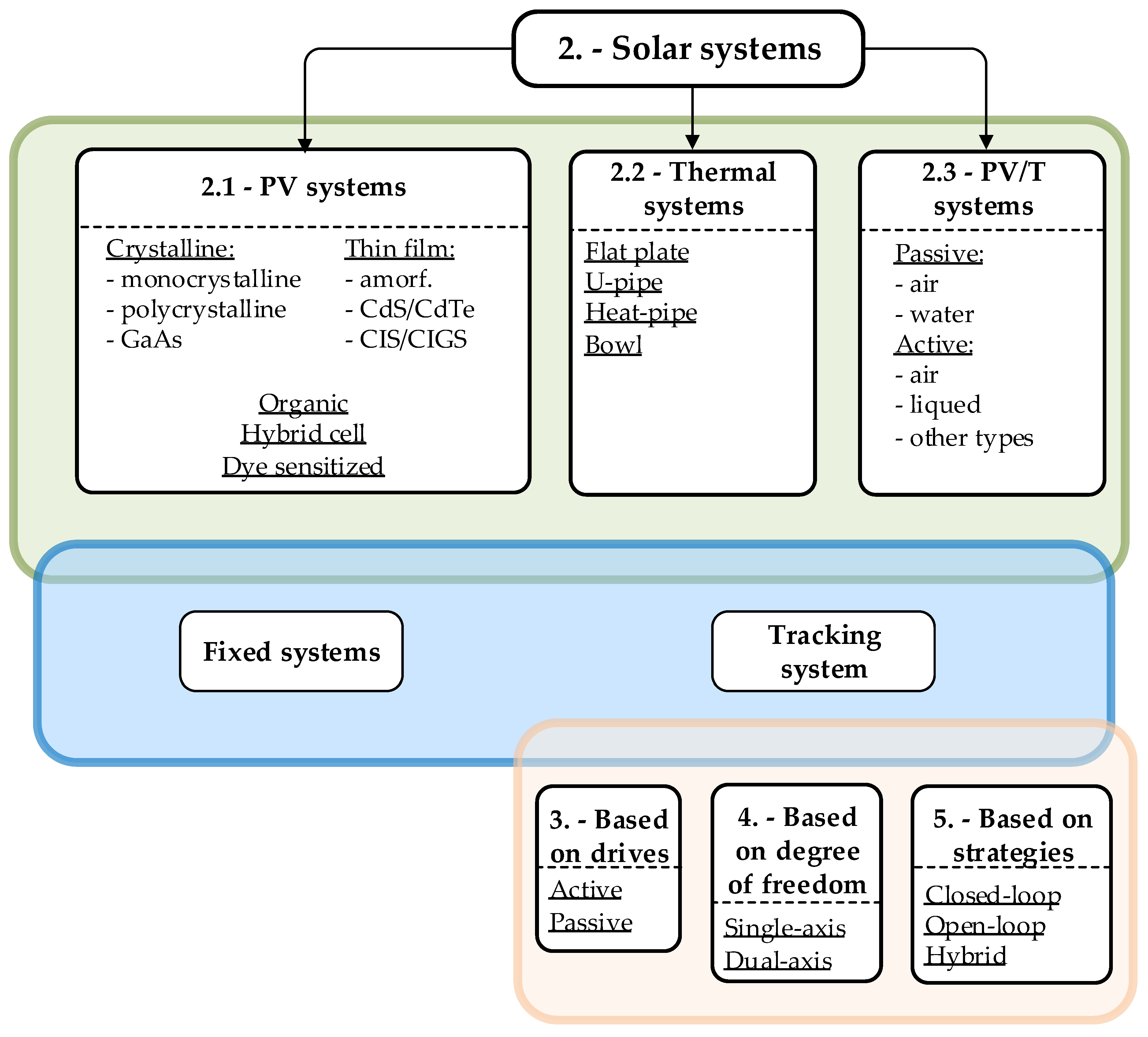
2. Solar Systems
- Direct generation of electrical energy: photovoltaic modules,
- Direct generation of heat: solar collectors,
- Direct generation of electrical energy and indirect generation of thermal energy: photovoltaic/thermal (PV/T) hybrid collectors.
- Fixed systems, and
- Tracking systems.
2.1. Photovoltaic Systems
2.2. Solar Thermal Systems
2.3. Photovoltaic/Thermal Systems
- passive cooling techniques, and
- active cooling techniques.
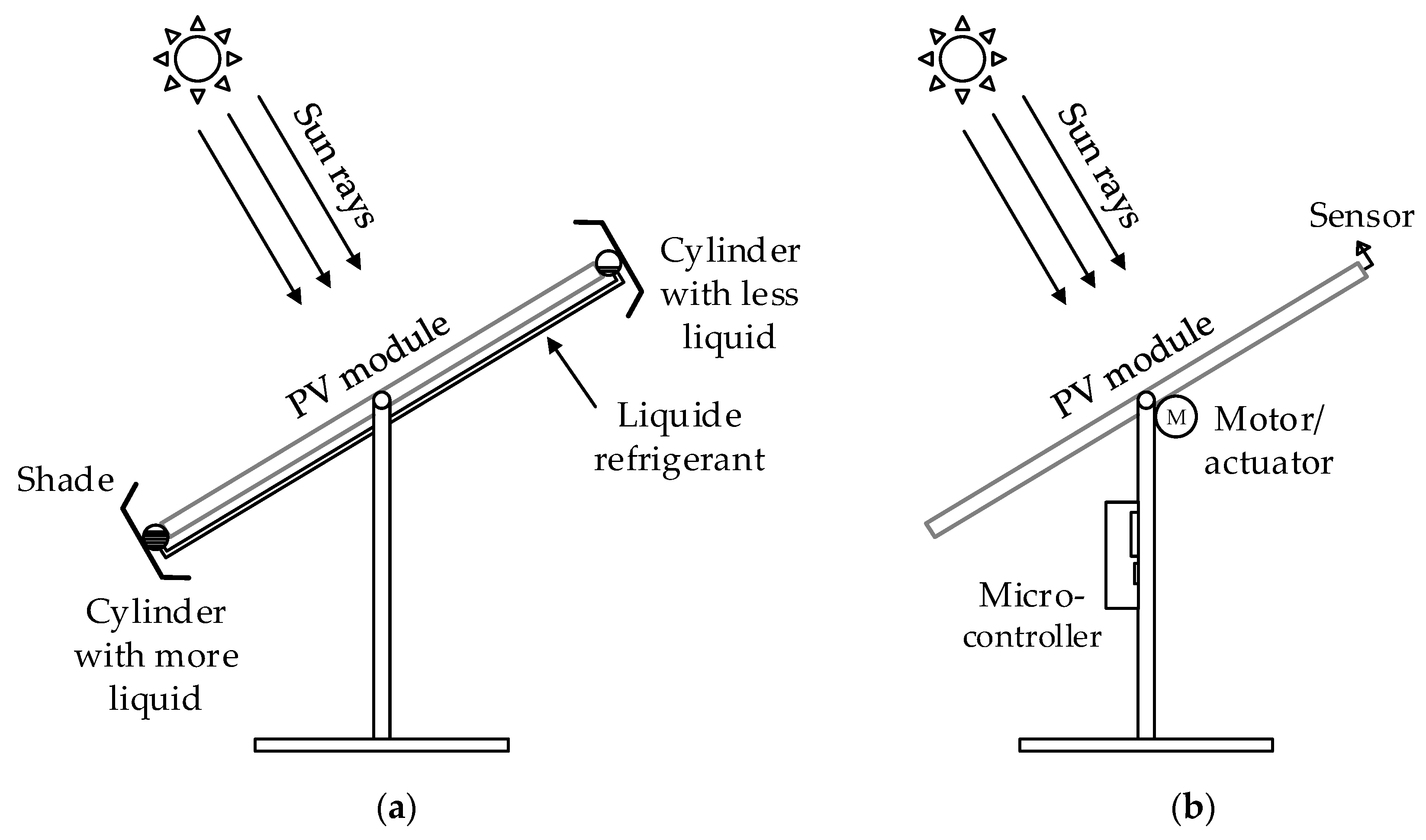
3. Classification Based on the Driving System
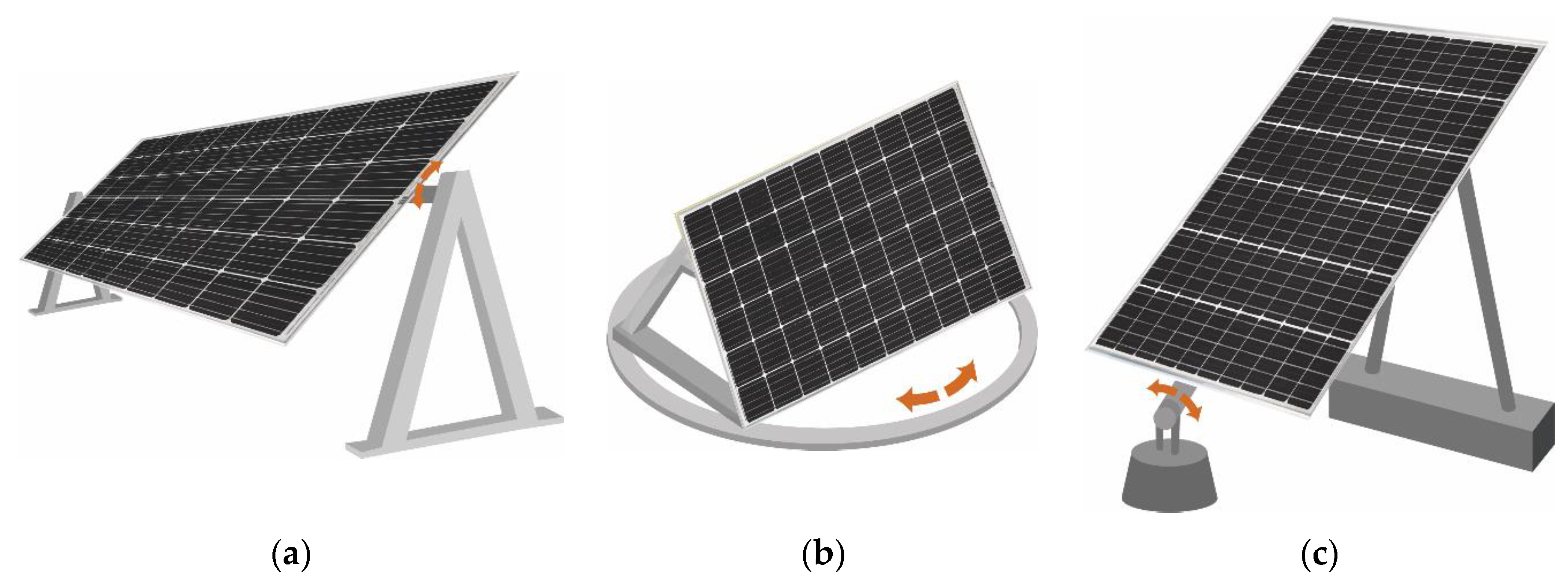
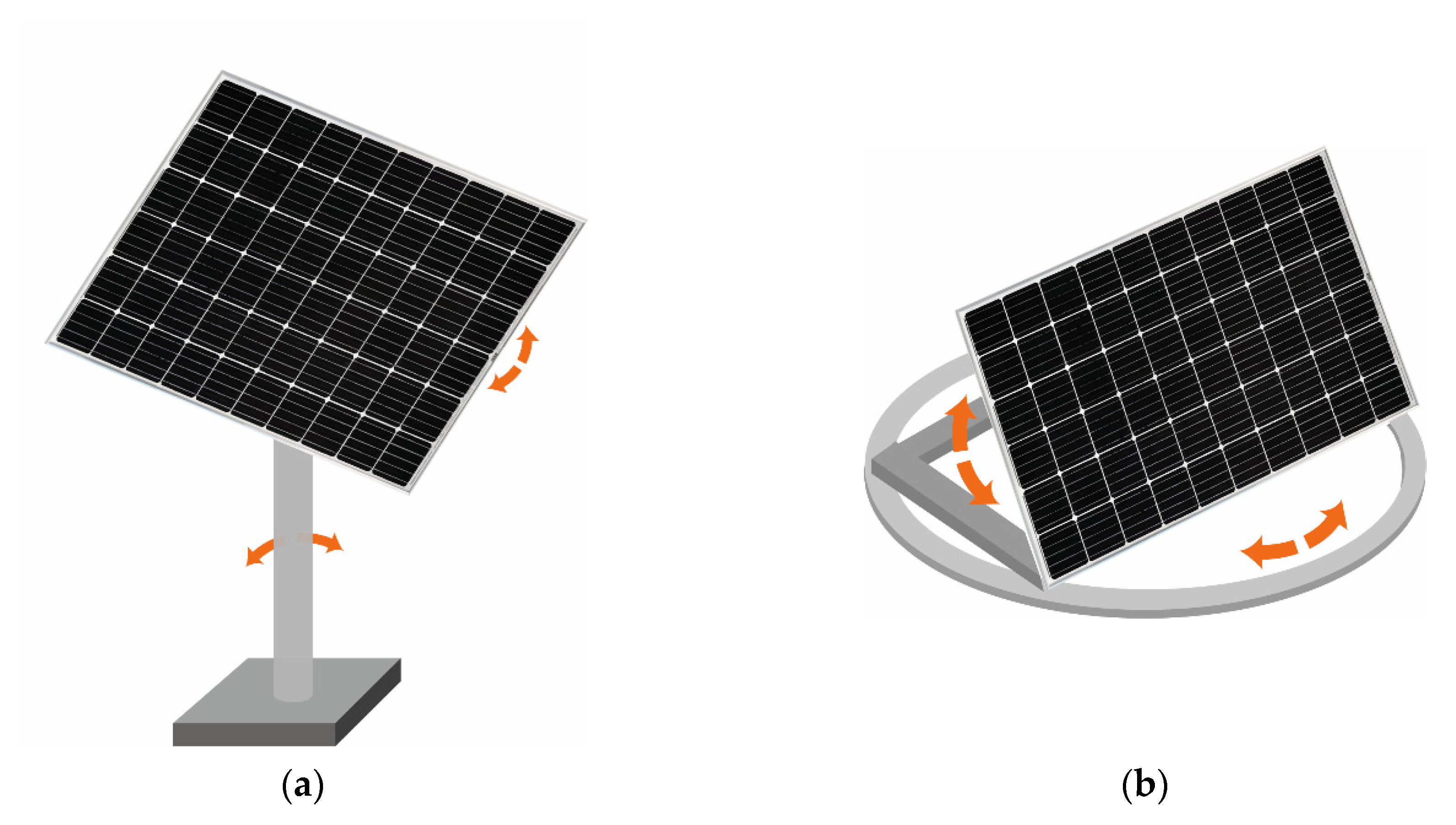
4. Classification Based on Degree of Freedom
- Fixed PV systems;
- Tracking PV systems;
- Single-axis tracking PV systems;
- Dual-axis tracking PV systems.
4.1. Single-Axis Photovoltaic Tracking System
- Tilted single-axis tracking system (TSAT) [53].
4.2. Dual-Axis Photovoltaic Tracking System
- Tip-tilt dual-axis tracking system (TTDAT) [53]
- Azimuth-altitude dual-axis tracking system [53]
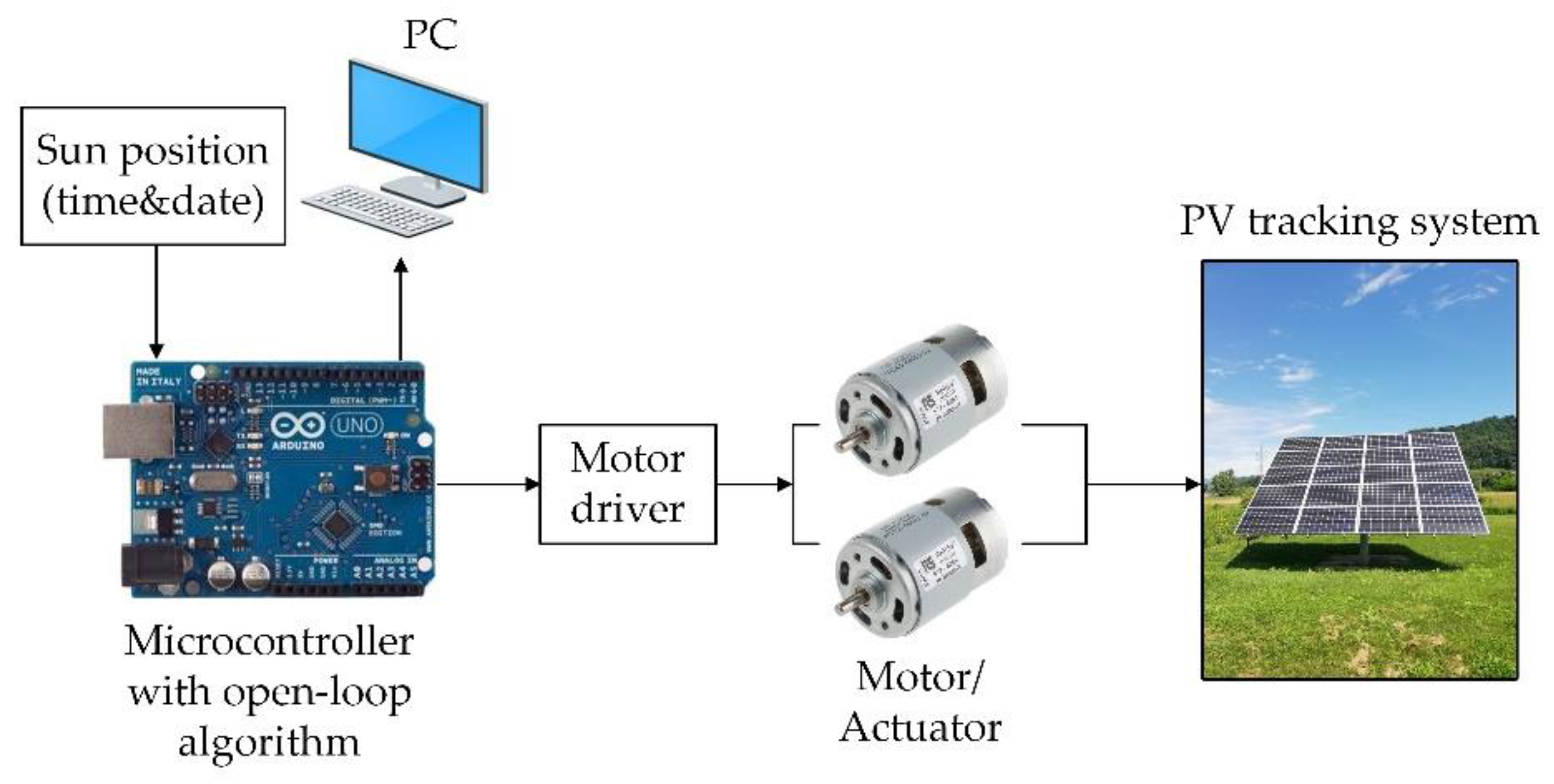
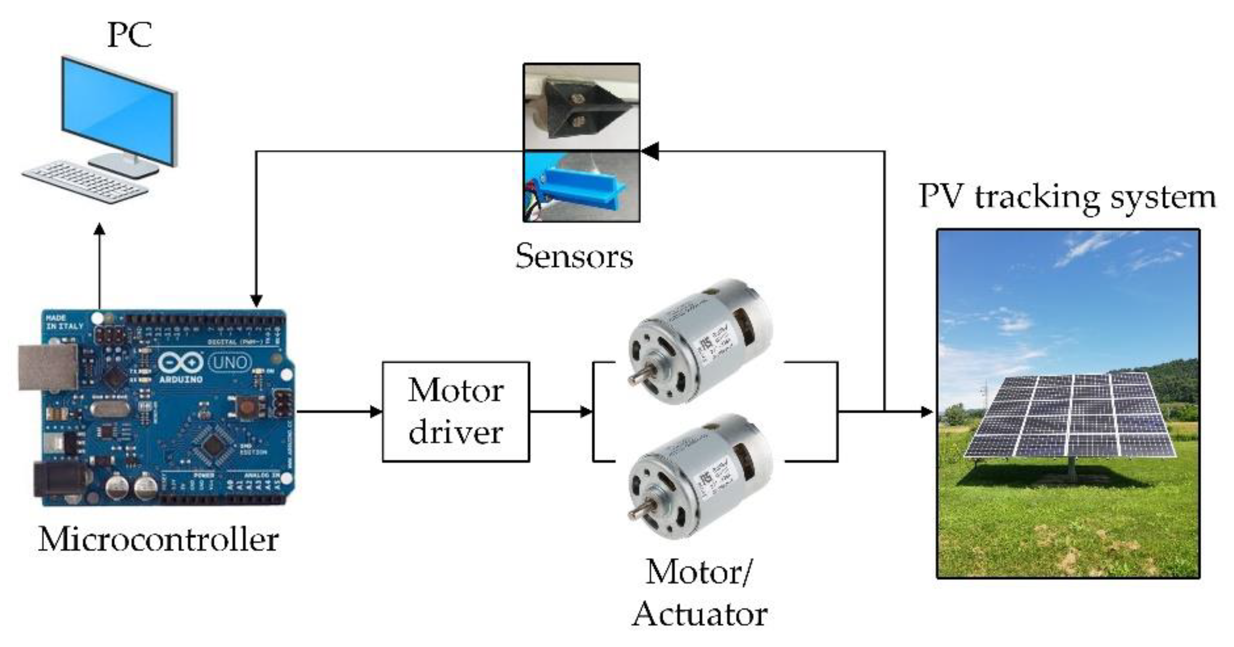
5. Classification Based on Control System
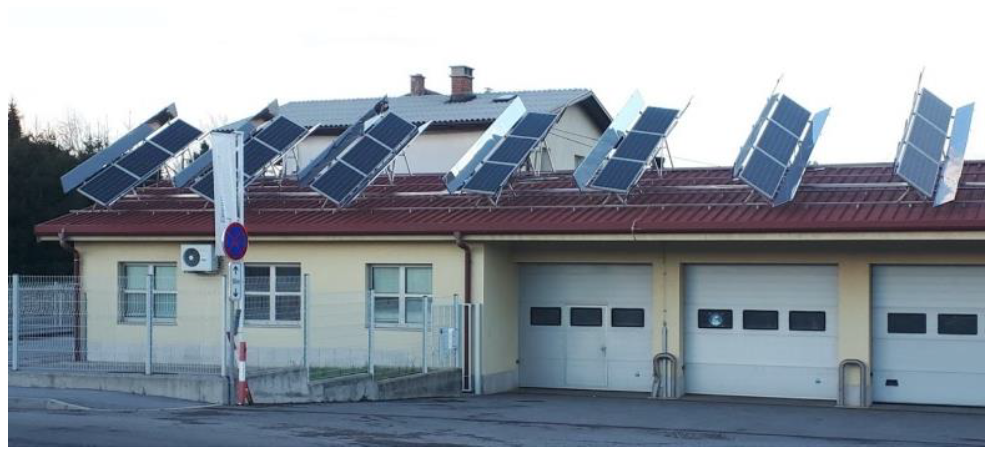
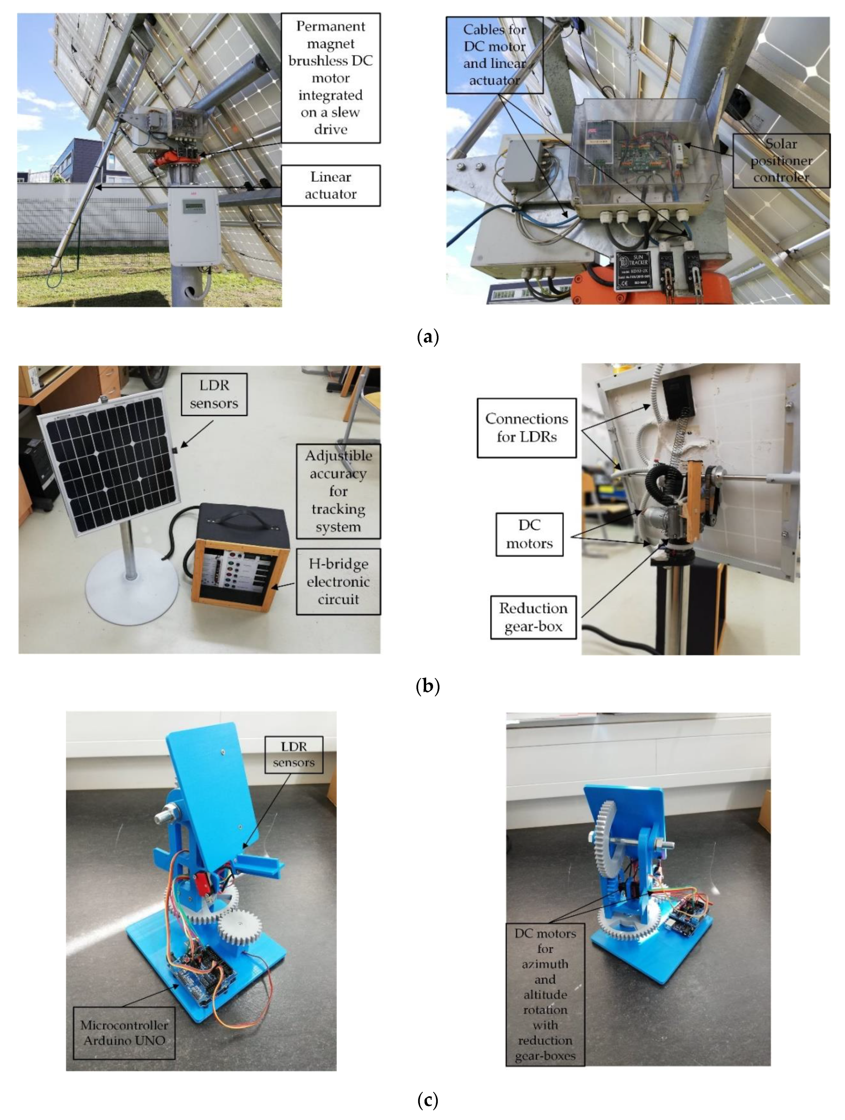
6. Commercial Photovoltaic Tracking Systems
7. Conclusion and Future Trends in Solar Photovoltaic Systems
- Single-axis and dual-axis photovoltaic tracking system, with appropriate control systems, the electrical energy can increase from 22–56%, compared to fixed PV system.
- Combinations of microprocessor- and sensor-based control systems represent the most commonly used control method as well as the most efficient.
- Active tracking systems use electrical drives to move the axis, which can consume a huge amount of electrical energy because of improper control systems. Therefore, it is necessary to optimize the power consumption of electrical drives, which can be done by reducing the number of motor movements.
- Sensor-based photovoltaic tracking systems are more expensive because of additional sensor devices, but provide lower tracking error (0.14°), compared to sensorless photovoltaic tracking systems (0.43°).
- Electric motors used in PV tracking applications are exposed to weather conditions and are therefore designed to withstand strong winds, and high temperatures and humidity. The most commonly used electric motor is permanent magnet brushless DC motors as they are easy to maintain.
- Novel innovative tracking systems will include dynamic weather forecasting and cooling of the PV system with wind or water.
Funding
Conflicts of Interest
References
- Data Platform. Available online: https://www.statista.com (accessed on 20 January 2020).
- Tyagi, V.; Rahim, N.A.; Rahim, N.; Jeyraj, A.; Selvaraj, L. Progress in solar PV technology: Research and achievement. Renew. Sustain. Energy Rev. 2013, 20, 443–461. [Google Scholar] [CrossRef]
- El-Adawi, M.K.; Al-Nuaim, I.A. The temperature functional dependence of VOC for a solar cell in relation to its efficiency new approach. Desalination 2007, 209, 91–96. [Google Scholar] [CrossRef]
- Singh, P.; Singh, S.N.; Lal, M.; Husain, M. Temperature dependence of I-V characteristics and performance parameters of silicon solar cell. Sol. Energy Mater. Sol. Cells 2008, 92, 1611–1616. [Google Scholar] [CrossRef]
- Siecker, J.; Kusakana, K.; Numbi, B.P. A review of solar photovoltaic systems cooling technologies. Renew. Sustain. Energy Rev. 2017, 79, 192–203. [Google Scholar] [CrossRef]
- Nijs, J.; Sivoththaman, S.; Szlufcik, J.; De Clercq, K.; Duerinckx, F.; Van Kerschaever, E.; Einhaus, R.; Poortmans, J.; Vermeulen, T.; Mertens, R. Overview of solar cell technologies and results on high efficiency multicrystalline silicon substrates. Sol. Energy Mater. Sol. Cells 1997, 48, 199–217. [Google Scholar] [CrossRef]
- Beg, R.A.; Sarker, M.R.I.; Parvez, R. An Experimental Investigation on Photovoltaic Power output through Single Axis Automatic controlled sun tracker. In Proceedings of the 4th BSME-ASME, Dhaka, Bangladesh, 27–29 December 2008. [Google Scholar]
- Zhao, Z.M.; Yuan, X.Y.; Guo, Y.; Xu, F.; Li, Z.G. Modelling and simulation of a two-axis tracking system. Proc. Inst. Mech. Eng. Part I J. Syst. Control Eng. 2010, 224, 125–137. [Google Scholar] [CrossRef]
- Karimov, K.S.; Saqib, M.A.; Akhter, P.; Ahmed, M.M.; Chattha, J.A.; Yousafzai, S.A. A simple photo-voltaic tracking system. Sol. Energy Mater. Sol. Cells 2005, 87, 49–59. [Google Scholar] [CrossRef]
- Khatib, T.T.N.; Mohamed, A.; Khan, R.J.; Amin, N. A Novel Active Sun Tracking Controller for Photovoltaic Panels. J. Appl. Sci. 2009, 9, 4050–4055. [Google Scholar] [CrossRef]
- Rubio, F.R.; Ortega, M.G.; Gordillo, F.; Lopez-Martinez, M. Application of new control strategy for sun tracking. Energy Convers. Manag. 2007, 48, 2174–2184. [Google Scholar] [CrossRef]
- Abdallah, S.; Badran, O.O. Sun tracking system for productivity enhancement of solar still. Desalination 2008, 220, 669–676. [Google Scholar] [CrossRef]
- Kacira, M.; Simsek, M.; Babur, Y.; Demirkol, S. Determining optimum tilt angles and orientations of photovoltaic panels in Sanliurfa, Turkey. Renew. Energy 2004, 29, 1265–1275. [Google Scholar] [CrossRef]
- Visa, I.; Diaconescu, D.V.; Duta, A.; Popa, V. PV tracking data needed in the optimal design of the azimuthal tracker’s control program. In Proceedings of the 11th International Conference on Optimization of Electrical and Electronic Equipment (OPTIM), Brasov, Romania, 22–24 May 2008; pp. 449–454. [Google Scholar]
- Alexandru, C. The design and optimization of a photovoltaic tracking mechanism. In Proceedings of the 2nd International Conference on Power Engineering, Energy and Electrical Drives Proceedings, Lisbon, Portugal, 18–20 March 2009. [Google Scholar]
- Alexandru, C.; Pozna, C. Simulation of a dual-axis solar tracker for improving the performance of a photovoltaic panel. Proc. Inst. Mech. Eng. Part A J. Power Energy 2010, 224, 797–811. [Google Scholar] [CrossRef]
- Alexandru, C.; Pozna, C. The optimization of the tracking mechanism used for a group of PV panels. In Proceedings of the International Conference on Renewable Energies and Power Quality (ICREPQ), Valencia, Spain, 15–17 April 2009. [Google Scholar]
- Alexandru, C.; Comsit, M. The energy balance of the photovoltaic tracking systems using virtual prototyping platform. In Proceedings of the 5th International Conference on the European Electricity Market (EEM), Lisbon, Portugal, 28–30 May 2008; pp. 1–6. [Google Scholar]
- Gonzalez Lopez, J.M.; Jimenez Betancourt, R.O.; Ramirez Arredondo, J.M.; Villalvazo Laureano, E.; Rodriguez Haro, F. Incorporating Virtual Reality into the Teaching and Training of Grid-Tie Photovoltaic Power Plants Design. Appl. Sci. 2019, 9, 4480. [Google Scholar] [CrossRef]
- Hafez, A.Z.; Yousef, A.M.; Harag, N.M. Solar tracking systems: Technologies and trackers drive types—A review. Renew. Sustain. Energy Rev. 2018, 91, 754–782. [Google Scholar] [CrossRef]
- Akash, A.; Shukla, K.; Manohar, M.S.R.; Dondariya, C.; Shukla, K.N.; Porwal, D.; Richhariya, G. Review on sun tracking technology in solar PV system. Energy Rep. 2020, 6, 392–405. [Google Scholar] [CrossRef]
- Ahmad, R.; Murtaza, A.F.; Sher, H.A. Power tracking techniques for efficient operation of photovoltaic array in solar applications—A review. Renew. Sustain. Energy Rev. 2019, 101, 82–102. [Google Scholar] [CrossRef]
- Mpodi, E.K.; Tjiparuro, Z.; Matsebe, O. Review of dual axis solar tracking and development of its functional model. Procedia Manuf. 2019, 35, 580–588. [Google Scholar] [CrossRef]
- Hafez, A.Z.; Yousef, A.M.; Soliman, A.; Ismail, I.M. A comprehensive review for solar tracking systems design in Photovoltaic cell, module, panel, array, and systems applications. In Proceedings of the IEEE 7th World Conference on Photovoltaic Energy Conversion (WCPEC) (A Joint Conference of 45th IEEE PVSC, 28th PVSEC & 34th EU PVSEC), Waikoloa Village, HI, USA, 10–15 June 2018; pp. 1188–1193. [Google Scholar]
- Al-Rousan, N.; Isa, N.A.M.; Desa, M.K.M. Advances in solar photovoltaic tracking systems: A review. Renew. Sustain. Energy Rev. 2018, 82, 2548–2569. [Google Scholar] [CrossRef]
- Singh, R.; Kumar, S.; Gehlot, A.; Pachauri, R. An imperative role of sun trackers in photovoltaic technology: A review. Renew. Sustain. Energy Rev. 2018, 82, 3263–3278. [Google Scholar] [CrossRef]
- Nsengiyumva, W.; Chen, S.G.; Hu, L.; Chen, X. Recent advancements and challenges in Solar Tracking Systems (STS): A review. Renew. Sustain. Energy Rev. 2018, 81, 250–279. [Google Scholar] [CrossRef]
- Sumathi, V.; Jayapragash, R.; Bakshi, A.; Akella, P.K. Solar tracking methods to maximize PV system output—A review of the methods adopted in recent decade. Renew. Sustain. Energy Rev. 2017, 74, 130–138. [Google Scholar] [CrossRef]
- Thorat, P.A.; Edalabadkar, A.P.; Chadge, R.B.; Ingle, A. Effect of sun tracking and cooling system on Photovoltaic Panel: A Review. Mater. Today Proc. 2017, 4, 12630–12634. [Google Scholar] [CrossRef]
- Suman, S.; Khan, M.K.; Pathak, M. Performance enhancement of solar collectors—A review. Renew. Sustain. Energy Rev. 2015, 49, 192–210. [Google Scholar] [CrossRef]
- International Electrotechnical Commision. IEC 61836 (Solar Photovoltaic Energy Systems—Terms and Symbols); International Electrotechnical Commision: London, UK, 2016. [Google Scholar]
- International Electrotechnical Commision. IEC 60904-3:2019 Photovoltaic Devices—Part 3: Measurement Principles for Terrestrial Photovoltaic (PV) Solar Devices with Reference Spectral Irradiance Data; International Electrotechnical Commision: London, UK, 2019. [Google Scholar]
- International Electrotechnical Commision. IEC 61277:1995 Terrestrial Photovoltaic (PV) Power Generating Systems—General and Guide; International Electrotechnical Commision: London, UK, 1995. [Google Scholar]
- Diez, F.J.; Navas-Gracia, L.M.; Martínez-Rodríguez, A.; Correa-Guimaraes, A.; Chico-Santamarta, L. Modelling of a flat-plate solar collector using artificial neural networks for different working fluid (water) flow rates. Sol. Energy 2019, 188, 1320–1331. [Google Scholar] [CrossRef]
- Tong, Y.; Lee, H.; Kang, W.; Cho, H. Energy and exergy comparison of a flat-plate solar collector using water, Al2O3 nanofluid, and CuO nanofluid. Appl. Therm. Eng. 2019, 159, 113959. [Google Scholar] [CrossRef]
- Kaya, H.; Arslan, K.; Eltugral, N. Experimental investigation of thermal performance of an evacuated U-Tube solar collector with ZnO/Etylene glycol-pure water nanofluids. Renew. Energy 2018, 122, 329–338. [Google Scholar] [CrossRef]
- Kim, H.; Kim, J.; Cho, H. Experimental study on performance improvement of U-tube solar collector depending on nanoparticle size and concentration of Al2O3 nanofluid. Energy 2017, 118, 1304–1312. [Google Scholar] [CrossRef]
- Shafieian, A.; Khiadani, M.; Nosrati, A. A review of latest developments, progress, and applications of heat pipe solar collectors. Renew. Sustain. Energy Rev. 2018, 95, 273–304. [Google Scholar] [CrossRef]
- Jayanthi, N.; Kumar, R.S.; Karunakaran, G.; Venkatesh, M. Experimental investigation on the thermal performance of heat pipe solar collector (HPSC). Mater. Today Proc. 2020, 26, 3569–3575. [Google Scholar] [CrossRef]
- Dehaj, M.S.; Mohiabadi, M.Z. Experimental investigation of heat pipe solar collector using MgO nanofluids. Sol. Energy Mater. Sol. Cells 2019, 191, 91–99. [Google Scholar] [CrossRef]
- Shafieian, A.; Parastvand, H.; Khiadani, M. Comparative and performative investigation of various data-based and conventional theoretical methods for modelling heat pipe solar collectors. Sol. Energy 2020, 198, 212–223. [Google Scholar] [CrossRef]
- Gao, Y.; Gao, C.; Xian, H.; Du, X. Thermal Properties of Solar Collector Comprising Oscillating Heat Pipe in a Flat-Plate Structure and Water Heating System in Low-Temperature Conditions. Energies 2018, 11, 2553. [Google Scholar] [CrossRef]
- Li, G.; Shittu, S.; Diallo, T.M.O.; Yu, M.; Zhao, X.; Ji, J. A review of solar photovoltaic-thermoelectric hybrid system for electricity generation. Energy 2018, 158, 41–58. [Google Scholar] [CrossRef]
- Fudholi, A.; Sopian, K.; Yazdi, M.H.; Ruslan, M.H.; Ibrahim, A.; Kazem, H.A. Performance analysis of photovoltaic thermal (PVT) water collectors. Energy Convers. Manag. 2014, 78, 641–651. [Google Scholar] [CrossRef]
- Sánchez, M.M.; Tamayo, D.F.B.; Estrada, R.H.C. Design and Construction of a Dual Axis Passive Solar Tracker, for Use on Yucatán. In Proceedings of the ASME 2011 5th International Conference on Energy Sustainability, Washington, DC, USA, 8 August 2011. [Google Scholar]
- Clifford, M.J.; Eastwood, D. Design of a novel passive solar tracker. Sol. Energy 2004, 77, 269–280. [Google Scholar] [CrossRef]
- Chong, K.K.; Wong, C.W. General formula for on-axis sun-tracking system and its application in improving tracking accuracy of solar collector. Sol. Energy 2009, 83, 298–305. [Google Scholar] [CrossRef]
- Huld, T.; Šuri, M.; Cebecauer, T.; Dunlop, E. Optimal mounting strategy for single-axis tracking non-concentrating PV in Europe. In Proceedings of the 23rd European Photovoltaic Solar Energy Conference, Valencia, Spain, 1–5 September 2008. [Google Scholar]
- Hein, M.; Dimroth, F.; Siefer, G.; Bett, A.W. Characterisation of a 300× photovoltaic concentrator system with one-axis tracking. Sol. Energy Mater. Sol. Cells 2003, 75, 277–283. [Google Scholar] [CrossRef]
- Guo, M.; Wang, Z.; Liang, W.; Zhang, X.; Zang, C.; Lu, Z.; Wei, X. Tracking formulas and strategies for a receiver oriented dual-axis tracking toroidal heliostat. Sol. Energy 2010, 84, 939–947. [Google Scholar] [CrossRef]
- Seme, S.; Sredenšek, K.; Štumberger, B.; Hadžiselimović, M. Analysis of the performance of photovoltaic systems in Slovenia. Sol. Energy 2019, 180, 550–558. [Google Scholar] [CrossRef]
- Li, G.; Tang, R.; Zhong, H. Optical Performance of Horizontal Single-Axis Tracked Solar Panels. Energy Procedia 2012, 16, 1744–1752. [Google Scholar] [CrossRef]
- International Electrotechnical Commision. IEC TC82/1722/NP: Solar Photovoltaic Tracking Systems—Part 1: Design Qualification for Horizontal One-Axis Solar Tracking System; International Electrotechnical Commision: London, UK, 2020. [Google Scholar]
- Li, Z.; Liu, X.; Tang, R. Optical performance of vertical single-axis tracked solar panels. Renew. Energy 2011, 36, 64–68. [Google Scholar] [CrossRef]
- Sefa, I.; Demirtaş, M.; Çolak, I. Application of one-axis sun tracking system. Energy Convers. Manag. 2009, 50, 2709–2718. [Google Scholar] [CrossRef]
- Huang, B.-J.; Sun, F.S. Feasibility study of one axis three positions tracking solar PV with low concentration ratio reflector. Energy Convers. Manag. 2007, 48, 1273–1280. [Google Scholar] [CrossRef]
- Zhu, Y.; Liu, J.; Yang, X. Design and performance analysis of a solar tracking system with a novel single-axis tracking structure to maximize energy collection. Appl. Energy 2020, 264, 114647. [Google Scholar] [CrossRef]
- Parthipan, J.; Nagalingeswara Raju, B.; Senthilkumar, S. Design of one axis three position solar tracking system for paraboloidal dish solar collector. Mater. Today Proc. 2016, 3, 2493–2500. [Google Scholar] [CrossRef]
- Huang, B.-J.; Ding, W.L.; Huang, Y.C. Long-Term field test of solar PV power generation using one-axis 3-position sun tracker. Sol. Energy 2011, 85, 1935–1944. [Google Scholar] [CrossRef]
- Huang, B.-J.; Huang, Y.-C.; Chen, G.-Y.; Hsu, P.-C.; Li, K. Improving Solar PV System Efficiency Using One-Axis 3-Position Sun Tracking. Energy Procedia 2013, 33, 280–287. [Google Scholar] [CrossRef]
- Kalogirou, S.A. Design and construction of a one-axis sun-tracking system. Sol. Energy 1996, 57, 465–469. [Google Scholar] [CrossRef]
- Tang, R.; Yu, Y. Feasibility and optical performance of one axis three positions sun-tracking polar-axis aligned CPCs for photovoltaic applications. Sol. Energy 2010, 84, 1666–1675. [Google Scholar] [CrossRef]
- Batayneh, W.; Bataineh, A.; Soliman, I.; Hafees, S.A. Investigation of a single-axis discrete solar tracking system for reduced actuations and maximum energy collection. Autom. Constr. 2019, 98, 102–109. [Google Scholar] [CrossRef]
- Huld, T.; Cebecauer, T.; Šuri, M.; Dunlop, E. An analysis of one-axis tracking strategies for PV systems in Europe. Prog. Photovolt. 2010, 18, 183–194. [Google Scholar] [CrossRef]
- Jamroen, C.; Komkum, P.; Kohsri, S.; Himananto, W.; Panupintu, S.; Unkat, S. A low-cost dual-axis solar tracking system based on digital logic design: Design and implementation. Sustain. Energy Technol. Assess. 2020, 37, 100618. [Google Scholar] [CrossRef]
- Sheu, B.-H.; Chiu, C.-C.; Lu, W.-T.; Lien, C.-C.; Liu, T.-K.; Chen, W.-P. Dual-Axis rotary platform with UAV image recognition and tracking. Microelectron. Reliab. 2019, 95, 8–17. [Google Scholar] [CrossRef]
- Sidek, M.H.M.; Azis, N.; Hasan, W.Z.W.; Ab Kadir, M.Z.A.; Shafie, S.; Radzi, M.A.M. Automated positioning dual-axis solar tracking system with precision elevation and azimuth angle control. Energy 2017, 124, 160–170. [Google Scholar] [CrossRef]
- Away, Y.; Ikhsan, M. Dual-Axis sun tracker sensor based on tetrahedron geometry. Autom. Constr. 2017, 73, 175–183. [Google Scholar] [CrossRef]
- Fathabadi, H. Comparative study between two novel sensorless and sensor based dual-axis solar trackers. Sol. Energy 2016, 138, 67–76. [Google Scholar] [CrossRef]
- Arbab, H.; Jazi, B.; Rezagholizadeh, M. A computer tracking system of solar dish with two-axis degree freedoms based on picture processing of bar shadow. Renew. Energy 2009, 34, 1114–1118. [Google Scholar] [CrossRef]
- Roth, P.; Georgiev, A.; Boudinov, H. Cheap two axis sun following device. Energy Convers. Manag. 2005, 46, 1179–1192. [Google Scholar] [CrossRef]
- Bakos, G.C. Design and construction of a two-axis Sun tracking system for parabolic trough collector (PTC) efficiency improvement. Renew. Energy 2006, 31, 2411–2421. [Google Scholar] [CrossRef]
- Abdollahpour, M.; Golzarian, M.R.; Rohani, A.; Zarchi, H.A. Development of a machine vision dual-axis solar tracking system. Sol. Energy 2018, 169, 136–143. [Google Scholar] [CrossRef]
- Fathabadi, H. Novel high accurate sensorless dual-axis solar tracking system controlled by maximum power point tracking unit of photovoltaic systems. Appl. Energy 2016, 173, 448–459. [Google Scholar] [CrossRef]
- Batayneh, W.; Owais, A.; Nairoukh, M. An intelligent fuzzy based tracking controller for a dual-axis solar PV system. Autom. Constr. 2013, 29, 100–106. [Google Scholar] [CrossRef]
- Yao, Y.; Hu, Y.; Gao, S.; Yang, G.; Du, J. A multipurpose dual-axis solar tracker with two tracking strategies. Renew. Energy 2014, 72, 88–98. [Google Scholar] [CrossRef]
- Sungur, C. Multi-Axes sun-tracking system with PLC control for photovoltaic panels in Turkey. Renew. Energy 2009, 34, 1119–1125. [Google Scholar] [CrossRef]
- Abdallah, S.; Nijmeh, S. Two axes sun tracking system with PLC control. Energy Convers. Manag. 2004, 45, 1931–1939. [Google Scholar] [CrossRef]
- Serhan, M.; El-Chaar, L. Two axes sun tracking system: Comparison with a fixed system. In Proceedings of the International Conference on Renewable Energies and Power Quality (ICREPQ), Granada, Spain, 23 March 2010. [Google Scholar]
- Duarte, F.; Gaspar, P.D.; Goncalves, L.C. Two axis solar tracker based on solar maps, controlled by a low-poer microcontroller. In Proceedings of the International Conference on Renewable Energies and Power Quality (ICREPQ), Granada, Spain, 23 March 2010. [Google Scholar]
- Sarker, M.R.I.; Pervez, M.R.; Beg, R.A. Design, Fabrication and Experimental study of a Novel Two-Axis Sun Tracker. Int. J. Mech. Mechatron. Eng. 2010, 10, 13–18. [Google Scholar]
- Mi, Z.; Chen, J.; Chen, N.; Bai, Y.; Fu, R.; Liu, H. Open-Loop solar tracking strategy for high concentrating photovoltaic systems using variable tracking frequency. Energy Convers. Manag. 2016, 117, 142–149. [Google Scholar] [CrossRef]
- Yang, C.-K.; Cheng, T.-C.; Cheng, C.-H.; Wang, C.-C.; Lee, C.-C. Open-Loop altitude-azimuth concentrated solar tracking system for solar-thermal applications. Sol. Energy 2017, 147, 52–60. [Google Scholar] [CrossRef]
- Melo, A.; Filho, D.O.; de Oliveira, M.J.M.; Zolnier, S.; Ribeiro, A. Development of a closed and open loop solar tracker technology. Acta Sci. Technol. 2017, 39, 177. [Google Scholar] [CrossRef]
- Huynh, D.C.; Nguyen, T.M.; Dunnigan, M.W.; Mueller, M.A. Comparison between open- and closed-loop trackers of a solar photovoltaic system. In Proceedings of the IEEE Conference on Clean Energy and Technology (CEAT), Langkawi, Malaysia, 18–20 November 2013; pp. 128–133. [Google Scholar]
- Lin, C.E.; Chen, C.H.; Huang, Y.C.; Chen, H.Y. An open-loop solar tracking for mobile photovoltaic systems. J. Aeronaut. Astronaut. Aviat. 2015, 47, 315–324. [Google Scholar]
- Chong, K.K.; Wong, C.W. Open-Loop azimuth-elevation sun-tracking system using on-axis general sun-tracking formula for achieving tracking accuracy of below 1 mrad. In Proceedings of the IEEE Photovoltaic Specialists Conference, Honolulu, HI, USA, 20–25 June 2010; pp. 3019–3024. [Google Scholar]
- Khan, R.A.; Mahmood, R.; Haque, A. Enhanced energy extraction in an open loop single-axis solar tracking PV system with optimized tracker rotation about tilted axis. J. Renew. Sustain. Energy 2018, 10, 045301. [Google Scholar] [CrossRef]
- Alexandru, C. A Novel Open-Loop Tracking Strategy for Photovoltaic Systems. Sci. World J. 2013, 2013, 205396. [Google Scholar] [CrossRef] [PubMed]
- Chowdhury, M.E.H.; Khandakar, A.; Hossain, B.M.; Abouhasera, R. A Low-Cost Closed-Loop Solar Tracking System Based on the Sun Position Algorithm. J. Sens. 2019, 2019, 3681031. [Google Scholar] [CrossRef]
- Garrido, R.; Díaz, A. Cascade closed-loop control of solar trackers applied to HCPV systems. Renew. Energy 2016, 97, 689–696. [Google Scholar] [CrossRef]
- Wang, J.-M.; Lu, C.-L. Design and Implementation of a Sun Tracker with a Dual-Axis Single Motor for an Optical Sensor-Based Photovoltaic System. Sensors 2013, 13, 3157–3168. [Google Scholar] [CrossRef]
- Zeroual, A.; Raoufi, M.; Ankrim, M.; Wilkinson, A.J. Design and construction of a closed loop sun-tracker with microprocessor management. Int. J. Sol. Energy 1998, 19, 263–274. [Google Scholar] [CrossRef]
- Klein, S.A.; Beckman, W.A. A general design method for closed-loop solar energy systems. Sol. Energy 1979, 22, 269–282. [Google Scholar] [CrossRef]
- Xu, J.; Yi, M.; Wang, Y.; Liu, Y. The design of closed-loop control system of solar automatical tracking. In Proceedings of the 2013 International Conference on Mechatronic Sciences, Electric Engineering and Computer, Shenyang, China, 29–22 December 2013; pp. 3745–3748. [Google Scholar]
- Johnson, R.; Bobruk, J.; Fromer, N.; McDermott, D. Integrated Closed Loop Tracking System for Rooftop Concentrator Modules. AIP Conf. Proc. 2010, 141, 1277. [Google Scholar]
- López, O.; Penella, M.T.; Gasulla, M. A Closed-Loop Maximum Power Point Tracker for Subwatt Photovoltaic Panels. IEEE Trans. Ind. Electron. 2011, 59, 1588–1596. [Google Scholar] [CrossRef]
- Wang, L.; Men, J.; Shao, L.; Dong, Z.; Liu, W. Research Progress of Solar Auto-Tracking System—Solar Hybrid Tracking Mode. Adv. Mater. Res. 2013, 706, 985–989. [Google Scholar] [CrossRef]
- Nur, M.; Tarequl, K. Design and Implementation of Hybrid Automatic Solar-Tracking System. J. Sol. Energy Eng. 2012, 135. [Google Scholar] [CrossRef]
- Safan, Y.M.; Shaaban, S.; El-Sebah, M.I.A. Hybrid control of a solar tracking system using SUI-PID controller. In Proceedings of the 2017 Sensors Networks Smart and Emerging Technologies (SENSET), Beirut, Lebanon, 12–14 September 2017; pp. 1–4. [Google Scholar]
- Safan, Y.M.; Shaaban, S.; Abu El-Sebah, M.I. Performance evaluation of a multi-degree of freedom hybrid controlled dual axis solar tracking system. Sol. Energy 2018, 170, 576–585. [Google Scholar] [CrossRef]
- Kuhn, V.N.; Gonzatti, F.; Franchi, D.; Miotto, M.; Camargo, M.N.; Farret, F.A. Hybrid motor driver for solar tracking systems. In Proceedings of the 12th IEEE International Conference on Industry Applications (INDUSCON), Curitiba, Brazil, 20–23 November 2016; pp. 1–6. [Google Scholar]
- Hong, T.; Jeong, K.; Ban, C.; Oh, J.; Koo, C.; Kim, J.; Lee, M. A Preliminary Study on the 2-axis Hybrid Solar Tracking Method for the Smart Photovoltaic Blind. Energy Procedia 2016, 88, 484–490. [Google Scholar] [CrossRef]
- Zhang, J.; Yin, Z.; Jin, P. Error analysis and auto correction of hybrid solar tracking system using photo sensors and orientation algorithm. Energy 2019, 182, 585–593. [Google Scholar] [CrossRef]
- Jiang, C.; Zhu, W.; Hu, Y.; Tu, X.; Wu, Y. Design of novel hybrid control solar tracking system. IOP Conf. Ser. Earth Environ. Sci. 2017, 69, 12198. [Google Scholar] [CrossRef]
- Lee, H.G.; Kim, S.S.; Kim, S.J. Development of a hybrid solar tracking device using a GPS and a photo-sensor capable of operating at low solar radiation intensity. J. Korean Phys. Soc. 2015, 67, 980–985. [Google Scholar] [CrossRef]
- Shingleton, J. One-Axis Trackers—Improved Reliability, Durability, Performance, and Cost Reduction. In Final Subcontract Technical Status Report, NREL—Subcontract Report; NREL/SR-520-42769; National Renewable Energy Laboratory: Denver, CO, USA, 2008; pp. 1–48. [Google Scholar]
- Goodrich, A.; James, T.; Woodhouse, M. NREL—Technical Report; NREL/TP-6A20-53347; National Renewable Energy Laboratory: Denver, CO, USA, 2012; pp. 1–55. [Google Scholar]
- Fu, R.; Feldman, D.; Margolis, R.U.S. Solar Photovoltaic System Cost Benchmark: Q1 2018; NREL—Technical Report; NREL/TP-6A20-72399; National Renewable Energy Laboratory: Denver, CO, USA, 2018; pp. 1–49. [Google Scholar]


| No. | Description | Remarks and Key Findings | Reference |
|---|---|---|---|
| 1. | Single-axis tracking system: 2500 W, 3500 kg, only MPPT algorithm, VISUAL C# programming language, two photoresistors, H-bridge drive circuit, DC motor (50 W and 24 V supply) | 45% higher electrical energy production compared to fixed PV system. | [55] |
| 2. | Single-axis tracking system: 1 m2 of surface, PLC programming, two bridge rectifiers (220 V AC – 24 V DC), division of the day into 4 identical intervals on which the motor speed is calculated | 22% higher productivity and increase of overall efficiency by 2%. | [12] |
| 3. | Single-axis tracking system: A novel design of single-axis three-position tracking PV module (morning, noon and afternoon), two photoresistors, additional low-concentration reflector | The results of the proposed tracking system show approximately 56% and 25.4% higher energy production compared to a fixed PV system with and without the use of low-concentration reflector. | [56] |
| 4. | Single-axis tracking system: Novel tracking structure for single-axis tracking system | Ratio of annual solar radiation incident between presented and dual-axis tracking system is 96.4%. | [57] |
| 5. | Single-axis tracking system: two LDR sensors, Programmable Interface Controller (PIC 16F84A) controls the H-bridge, DC motor | Development of simple single-axis tracking system that is controlled through LDR sensors and increases the energy production by approximately 20%. | [58] |
| 6. | Single-axis tracking system: Three-positional single-axis tracking system, DC motor (5 W), sensor for axis rotation, microprocessor PIC18F452 | 35.6% higher daily electrical energy production (clear weather) compared to fixed PV system and 18.5–28% higher monthly electrical energy production; The results show very similar performances of the proposed tracking system compared to the dual-axis continuous tracking system. | [59] |
| 7. | Single-axis tracking system: Three-positional single-axis tracking system, microprocessor-based controller (rotation of the tracking systems three times a day – morning, noon and afternoon). | On a clear day, the increase in energy production is around 39%.The installation cost is very similar to the cost of a commercial PV tracking system, but providing 25–37% higher energy production. | [60] |
| 8. | Single-axis tracking system: three light-dependent resistors (LDRs) - 15 Ω in direct sunlight and 300 Ω in the shade (penumbra), DC motor (12 V), reduction gearbox (ratio of 45:1). | The complete cost of the entire mechanism including the DC motor is US$ 250, while the control system cost is US$ 160. The price for the control system stays the same irrespective to the PV systems size. | [61] |
| 9. | Single-axis tracking system: A novel design of single-axis three-position (3P) tracking polar-axis aligned compound parabolic concentrator (CPC) was presented and theoretically studied. The control of altitude angles of CPCs is achieved by time-based or sensor-based control system. | The comparison was made for three different cases: 1.) between the 3P-CPC tracking system and the East-West-CPC tracking system, and 2.) between the 3P-CPC tracking system and a fixed (south oriented) system. The results show 26–45% and 190–240% higher annual solar gain for 3P-CPC. | [62] |
| 10. | Single-axis tracking system: The proposed discrete single-axis tracking system moves only three times a day. The tracking movement and the calculation of optimal angles is based on weather-time data. | The experimental results show that using the proposed tracking system yielded approximately 91–94% of solar energy compared to a continuous single-axis tracking system (three times per hour). | [63] |
| 11. | Single-axis tracking strategies: The authors present an analysis of single-axis tracking strategies for PV systems in Europe. The method for calculating the performance of PV modules under different geographic conditions is based on measurements of solar radiation and temperature. | The results for southern, central and northern Europe showed that energy yields increased by 30%, 25%, and 50% compared to a fixed PV system. The comparison was made between two different types of single-axis tracking system that works almost like a dual-axis tracking system. | [64] |
| 12. | Dual-axis tracking system: polycrystalline silicon PV module (383 × 489 × 18 mm3 - width × height × depth), a linear actuator and DC motor is used, microcontroller “Arduino Mega 2560” (54 digital and 12 analogue inputs, 12 V supply), the motor is controlled by drive using pulse width modulation (PWM). | The experimental results show 44.89% higher efficiency using the presented system compared to fixed PV system. The installation cost of the presented system is $92, from which we can conclude that the system is cost-effective. The costs can be reimbursed after 754 days, and 1130 days for electricity prices of 0.3 $/kWh and 0.2 $/kWh. | [65] |
| 13. | Dual-axis tracking system: Large-scale dual-axis sun tracking system with multiple row elevation structures and a vertical-axis rotating platform. Installation power 60 kW, 35 m diameter, transmission mechanism rotates the whole rotating platform, an AC motor (750 W) with a gearbox, 22 DC motors (15 W) for elevation movements, cylindrical pins and a double layer pin-gear. | A new design concept of a large-scale dual-axis tracking system. The energy consumption of the driving system ranges between 0.4 to 0.5% of the total energy generation. New improvements can be made: wireless broadcasting method for tracking signal and using open-loop and closed-loop control scheme at the same time. | [6] |
| 14. | Dual-axis tracking system: unmanned aerial vehicle (UAV) image recognition and tracking, thermal imager and full-color camera, two-axis step motor | This study successfully completed the tracking task using thermal and full color image methods at 30 m and 100 m. This tracking system also smoothly allow Google Maps to perform dynamic UAV path tracking. | [66] |
| 15. | Dual-axis tracking system: two actuators for rotation and movement, DC motor for azimuth rotation and linear motion DC motor for tilt movement; PIC18f4680 (main controller – power supply 7–24 V), PIC18f4431 (Azimuth controller), PIC18f4431 (Altitude controller), GPS sensor. | The energy consumption of the tracking system is low, with the highest recorded value of 14.4 Wh/day. Furthermore, the power consumed by azimuth and altitude trackers are only 0.5 mWh and 0.23 mWh per degree, respectively. The proposed dual-axis tracking system can generate 12.8% and 26.9% higher power than fixed PV systems on a heavy and clear overcast condition. | [67] |
| 16. | Dual-axis tracking system: three light-dependent-resistors set in a tetrahedron, PID microprocessor, servo-motor. | Due to tetrahedron geometry, the LDRs possesses the maximum wide Field of View (FOV) of 289.4°. The results show very small error for single light source of 1.67° and 5.4° for multiple light sources. | [68] |
| 17. | Dual-axis tracking system: Comparison between novel sensorless and sensor-based dual-axis tracking system. Sensorless: microcontroller MC68HC11A8, DC/PWM converter, azimuth and altitude gear box, stepper motors 1 and 2. Sensor-based: Same as sensorless, but with additional irradiance sensor. | The tracking error is 0.43° and 0.14° for sensorless and sensor-based tracking system, respectively. Sensor-based tracking system receives better results for average daily solar energy compared to sensorless tracking system. | [69] |
| 18. | Dual-axis tracking system: The proposed dual-axis tracking system is based on picture processing of bar shadow and consists of two DC motors (12 V DC), AVR microcontroller, LDR sensors and analog/digital converter (ADC). | The presented tracking system can be used in various applications, such as the regulation of solar panels on space stations and satellites, or for processing the image of the sun, because of a simple computer control system. | [70] |
| 19. | Dual-axis tracking system: The authors present low-cost dual-axis tracking system consisting of a pyrheliometer for direct solar radiation measurements, two stepper motors for axis movement, a central processing unit (CPU), position sensor and solar radiation sensor. | The experimental results of irradiance were compared with Kipp/Zonen and two Eppley pyrheliometers mounted at INTRA sun tracking systems. The advantage of the proposed model is the external installation of electronics, which enables easier and more flexible upgrading of the mechanical part of the tracking system. | [71] |
| 20. | Dual-axis tracking system: The author presents continuous dual-axis tracking system consisting of two electronic circuits (comparators and solar intensity level), four relays, two phototransistors, two AC Siemens motors (0,37 kW/1370 rpm and 0,75 kW/915 rpm), gearbox MOTOVARIO and C+ programming language. | The experimental results show 46.46% higher gain compared to a fixed photovoltaic system under clear weather conditions. However, the efficiency of tracking system is reduced significantly in case of cloudy weather conditions (low intensity of solar radiation), due to sensor-based technology. | [72] |
| 21. | Dual-axis tracking system: The proposed tracking system works based on processing images of a bar shadow. It consists of shadow-casting object, a webcam, stepper motor, Arduino UNO microcontroller and other components that are common with other dual-axis tracking systems. | The proposed tracking system can increase power output by 25–45% compared to a fixed PV system, with accuracy of 2°. The accuracy or tracking error is within the limits of the stepper motor, which was used to reduce costs and prevent the use of complicated drives. | [73] |
| 22. | Dual-axis tracking system: Sensorless dual-axis tracking system controlled by MPPT unit. It consists of a microcontroller MC68HC11A8, DC-PWM converter, azimuth and altitude gear box, MPPT controller, and stepper motor 1 and 2. | The tracking error of the proposed dual-axis tracking system is remarkable (0.11°) that it is less than the tracking errors of other presented tracking systems. An increase of energy efficiency reaches values from 28.8% to 43.6%, depending on the seasons. | [74] |
| 23. | Dual-axis tracking system: It consists of 50 W monocrystalline silicon PV module, four PV cells are used as sensors and installed at all four corners, two DC motors for altitude and azimuth movement, controller, which collects the data from PV cells and calculates the error, and fuzzy controller, which collects the data of errors and calculate the suitable signal (duty cycle (D) for the PWM) for DC motors. | The proposed fuzzy logic-based controller can achieve the highest efficiency and results confirm reliable performance at all times. The fuzzy logic-based controller allows the interaction of multiple outputs and inputs. | [75] |
| 24. | Dual-axis tracking system: The author presents two tracking strategies. Both types of mechanisms consist of connecting rods, linear actuators for different movements, DC motors, drive circuit for DC motors microprocessor ARM S3C2440X, analogue to digital converter and signal processing unit. | The proposed tracking system uses both sensor-based and time-based control for optimal operation at different weather conditions. The accuracy test indicates that the tracking error is within 0.15°, while the other strategy might have higher tracking error, but its annual average cosine loss is estimated to be below 1.3%. | [76] |
| 25. | Dual-axis tracking system: The tracking system is controlled via a programmable logic control (PLC) and uses the following components: amorphous (KA 64) PV module, actuator motors with voltage power supply 24 V DC and control voltage of 2–10 V DC, PLC control unit Siemens S7 200 and analog module EM 232. | The experimental study was conducted for 37.6° latitude, where 42.6% more energy was obtained from the proposed tracking system when compared to the fixed PV system. This type of tracking system is superior to sensor-based tracking systems because LDR sensors do not detect the sun in cloudy weather conditions. | [77] |
| 26. | Dual-axis tracking system: The authors present a dual-axis tracking system with PLC control system. The PLC system uses the already known programming functional language from other studies and consists of two types of movement: forward (from sunrise to noon) and backward (from noon to sunset). | The experimental results of daily solar energy were compared with a single-axis tracking system from other studies. The results of single-axis tracking system ranged from 19.7% to 24.5%, while the results for proposed system were almost double (41.34%). Both tracking systems were compared to a fixed photovoltaic system tilted at 32°. | [78] |
| 27. | Dual-axis tracking system: The proposed tracking system consists of two AC motors, 80 W PV module, driver circuit for motor movement, two multiplexers, counter, logic circuit, PIC16F974 microcontroller and four phototransistors. | The experimental results of the proposed system show a 24% and 20% increase in energy production for clear and cloudy weather conditions. | [79] |
| 28. | Dual-axis tracking system: The proposed tracking system is controlled by time-date microcontroller based on solar maps. Solar maps can accurately predict the movement of the sun without any use of sensors, thus making it easier to avoid the reduction of energy production during bad weather. | The advantage of the proposed tracking system is the solar map, which is loaded in the microcontroller, and makes it easier to use the tracking system in any location without additional settings. | [80] |
| 29. | Dual-axis tracking system: The authors presents a novel design of a dual-axis tracking system, which consists of a microcontroller with analog/digital converter (ADC) AT89C51, driver circuit ULN2003, two stepper motors and LDR sensors. | The experimental results show 30–45% higher energy production compared to a fixed photovoltaic system with an average intensity of solar radiation (1100 W/m2). | [81] |
| No. | Description | Remarks and Key Findings | Reference |
|---|---|---|---|
| 1. | Closed-loop tracking system: The proposed study presents a dual-axis tracking system (closed-loop) using the sun-position algorithm uploaded in an 8-bit microcontroller. The sun-positing algorithm requires real-time measurements that can be obtained with a real-time clock (RTC). | The results show that the implementation of the sun position algorithm in the sun tracking system helps to increase the efficiency of the optical tracking system and fixed system (using LDRs) by 2.1% and 13.9%, respectively. | [90] |
| 2. | Closed-loop tracking system: The proposed study presents closed-loop control algorithm with an inner-outer loop cascade conceived for solar tracking systems applied to high concentration photovoltaic (HCPV) systems. The DC motors are regulated through the inner loop for angular position through a nonlinear proportional-proportional integral (NP-PI) controller, while the outer loop tracks the sun using a proportional integral (PI) controller. | The results show that the proposed cascade algorithm is better than the PI controller without an internal loop in terms of maximum tracking error (MTE) and filtered mean square error (FMSE). The proposed cascade algorithm produces an FMSE of 1.14 versus a value of 14.47 for the PI controller. In contrast, the proposed cascade controller has an MTE of 0.014° against a value of 0.134° for PI controller. | [91] |
| 3. | Open-loop tracking system: The proposed study presents an open-loop solar tracking strategy for HCPV systems using variable tracking frequency. The tracking frequency control code is programmed according to the solar velocity in different times and dates. | The results show that increasing the tracking frequency consequently reduces the misfit angle between the normal of the PV module and incident sunlight the normal of the PV module, but this increases the consumption of the required additional energy of the motor drive. An example was made for the summer solstice, on which the solar tracking step period was increased from 4 min to 9 min from 6.00 a.m. to 12.00 a.m. and reduced from 9 min to 4 min from 12.00 a.m. to 6.00 p.m. | [82] |
| 4. | Open-loop and closed-loop tracking system: The proposed study compares closed-loop and open-loop tracking system. The closed-loop tracking system uses LDRs, while the open-loop tracking system uses an algorithm that works on the basic relationship between the sun and the observed surface. The open-loop tracking system was also compared to control the system using fixed time intervals. | The simulation was made with different tracking parameters for five different latitudes. The results show an average gain of 33.0% for the closed-loop tracking system and 28.5% for the open-loop tracking system. Minor difference was observed between the proposed open-loop tracking system compared to control system using fixed time intervals. | [84] |
| 5. | Closed-loop tracking system: The paper presents implementation and design of dual-axis tracking system with only one DC motor using optical sensor-based technology. The sensor-based controller consists of LDRs, comparator (basic operational amplifier) and differential amplifier. The imbalance in voltage generated by the LDRs is amplified, which generate the error voltage. The error voltage is, therefore, compared in comparator with a specific threshold. | The advantages of the proposed closed-loop tracking system are cost-effective control system, PV inverter, movement of both axes (azimuth and altitude) simultaneously, and satisfactory tracking accuracy. The results show that with the help of the proposed closed-loop tracking system, energy production is increased by 28.31% for a partly cloudy day. | [92] |
| 6. | Open-loop tracking system: The proposed study presents a novel open-loop tracking strategy to increase the PV efficiency by increasing the rate of solar radiation utilization. The tuning of the controller is achieved by a parametric optimization, using response surface methodology techniques and design of experiments, in a multiple regression. | The advantages of the proposed open-loop tracking systems are simplicity, generality, and performance. The results show the operation of the presented system, without the need to use complicated and expensive technologies. The proposed tracking system can be used for any type of tracking load-bearing construction. | [89] |
| 7. | Hybrid control tracking system: The proposed study presents the simulation, modelling and design of dual-axis tracking system with a hybrid controlled tracking system. The system uses a multi-Degree of Freedom Simplified Universal Intelligent Proportional Integral Differential controller (MDOF SUI PID). | The performance of the presented system was evaluated by the standard tracking error, tracking accuracy, the performance ratio and maximum generated power. The results of the above evaluations are as follows: 23.3% more generated power, 95–97% performance ratio (compared to classical closed-loop and open-loop tracking systems), 0.12° of tracking error and 0.18° of average azimuth error. | [101] |
| 8. | Hybrid control tracking system: The proposed paper presents a hybrid PV tracking system that uses GPS and photodiodes as part of the closed-loop system and orientation algorithm as part of the open-loop system. | The analysis of the proposed system was made for tracking errors, calculation errors and solar time algorithm error. The maximum calculation errors of hour angle, altitude angle, declination angle, and azimuth angle are 0.12, 0.47, 0.51, and 0.91 respectively, which show that the proposed tracking system has good accuracy. | [104] |
© 2020 by the authors. Licensee MDPI, Basel, Switzerland. This article is an open access article distributed under the terms and conditions of the Creative Commons Attribution (CC BY) license (http://creativecommons.org/licenses/by/4.0/).
Share and Cite
Seme, S.; Štumberger, B.; Hadžiselimović, M.; Sredenšek, K. Solar Photovoltaic Tracking Systems for Electricity Generation: A Review. Energies 2020, 13, 4224. https://doi.org/10.3390/en13164224
Seme S, Štumberger B, Hadžiselimović M, Sredenšek K. Solar Photovoltaic Tracking Systems for Electricity Generation: A Review. Energies. 2020; 13(16):4224. https://doi.org/10.3390/en13164224
Chicago/Turabian StyleSeme, Sebastijan, Bojan Štumberger, Miralem Hadžiselimović, and Klemen Sredenšek. 2020. "Solar Photovoltaic Tracking Systems for Electricity Generation: A Review" Energies 13, no. 16: 4224. https://doi.org/10.3390/en13164224
APA StyleSeme, S., Štumberger, B., Hadžiselimović, M., & Sredenšek, K. (2020). Solar Photovoltaic Tracking Systems for Electricity Generation: A Review. Energies, 13(16), 4224. https://doi.org/10.3390/en13164224


