Article

Analysis of the DC Fault Current Limiting Characteristics of a DC Superconducting Fault Current Limiter Using a Transformer

Department of Electrical Engineering, Soongsil University, 369, Sangdo-ro, Dongjak-gu, Seoul 156-743, Korea
*
Author to whom correspondence should be addressed.
Energies 2020, 13(16), 4210; https://doi.org/10.3390/en13164210
Submission received: 21 July 2020 / Revised: 8 August 2020 / Accepted: 10 August 2020 / Published: 14 August 2020
(This article belongs to the Section A1: Smart Grids and Microgrids)

Abstract

:
Recently, a lot of interesting research has been conducted to solve the fault current problem of the DC system. In long-distance transmission, DC transmission is more economical than AC transmission. The connection of power grids with a DC system can also better control the power flow and provide high stability. However, the control of the fault current in a DC system is more difficult to handle than in an AC system because the DC system does not make a zero point, unlike the AC system. In addition, there is a disadvantage, in that an arc occurs when a circuit breaker operates. In this paper, a new type of DC superconducting fault current limiter (SFCL) is proposed. This new type of SFCL is composed of two superconducting elements, a current limiting resistor/reactor (CLR), and a transformer. With the proposed SFCL, the DC fault current limiting experiments were performed and the DC fault current limiting characteristics of this SFCL due to the component of the CLR were analyzed.

1. Introduction

With the development of the power transmission method, the power transmission loss is reduced by transmitting power at a high voltage. For long-distance transmission, the DC system is more effective in terms of transmission loss than the AC system. In addition, the connection of power grids to different specifications using the DC system will reduce losses and make it efficient for long-distance transmission, as there is no change in voltage and polarity. Therefore, the DC system is attracting attention because a more stable grid can be kept [1,2,3]. However, one of the important tasks in the operation of the DC system is the limiting and blocking of the DC current. In the DC system, the DC fault current must quickly be limited to prevent damage to the connected system. As one of the countermeasures, it is necessary to introduce a superconducting fault current limiter (SFCL). The SFCL has the advantage to operate very quickly because it uses the quench phenomenon of the superconducting material itself. In a normal state, the SFCL has no loss of electricity due to having zero resistance. When an overcurrent happens, the quench occurrence in the superconducting element of the SFCL quickly suppresses the increase in the fault current [4,5,6,7,8,9,10].
On the other hand, for the application of an SFCL in a real power system, it needs the many superconducting elements comprising the SFCL for a larger capacity of the SFCL. To overcome this, various types of SFCLs have been developed. For example, various structural studies of SFCLs, such as the trigger-type SFCL, double quench-type SFCL and transformer-type SFCL, are underway [11,12,13,14,15,16]. If an SFCL is applied to a system, it is not necessary to replace the circuit breaker of the transmission and distribution system when the size of the failure due to the increase in the capacity of the power system increases. Therefore, it can be expected to have a large economic effect in these areas. For example, it may be more economical to apply an SFCL than the cost of replacing the entire circuit breaker with a larger breaking capacity. Research on SFCL has been actively conducted, and in France, research is underway to apply SFCL to the transmission lines, and in Japan, an SFCL for application in the distribution line is being developed. In Korea, a 22.9 kV and 154 kV SFCL is being developed [17,18,19,20,21,22]. Although the introduction of a large-capacity SFCL may not always be economical in terms of price, the introduction of an SFCL has a great advantage in terms of performance compared to any other current limiter. In addition, the DC system has a difficulty in blocking since a zero point is not created, unlike the AC system. If the high level of fault current is cut off, an arc may occur, and the blocking may also fail. However, if the fault current level is reduced by the SFCL, it will also help to improve breaker operation.
In this paper, the DC fault current limiting characteristics of a DC SFCL using a transformer, as one of the DC SFCLs with two triggering current levels, was analyzed through short-circuit tests. The DC short-circuit experiment was constructed and the DC short-circuit tests for the DC SFCL using a transformer were carried out. Through the DC short-circuit tests, the effective DC current limiting characteristics due to the component of the current limiting resistor/reactor (CLR) comprising the DC SFCL using a transformer were analyzed.

2. Principle of Operation and Experiment of the DC SFCL

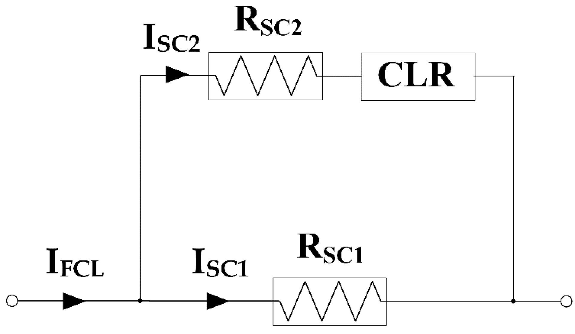
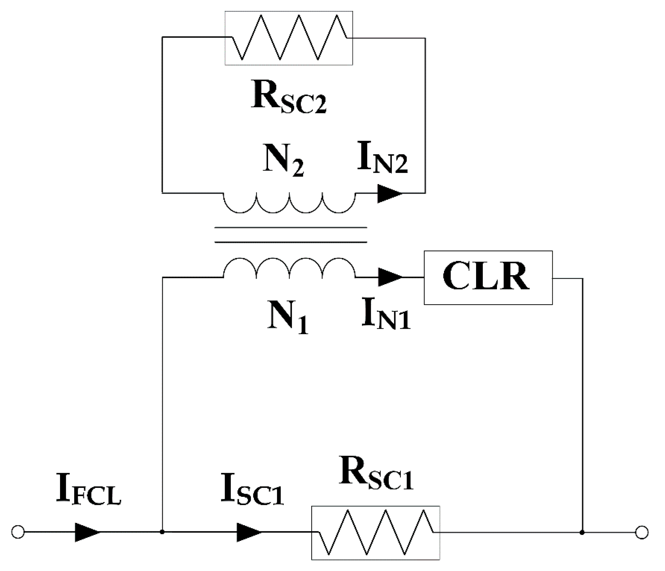
2.1. Configuration and Principle of Operation

Figure 1 shows the configuration of a DC SFCL with two triggering current levels, which was reported previously for an AC system [16]. The superconducting element RSC2 and CLR are connected in series, and the superconducting element RSC1 is configured in parallel with RSC2. This DC SFCL is designed with two superconducting elements to distribute the power burden of the superconducting elements. In addition, a CLR is included to reduce the power burden of the superconducting element. When a small fault current flows, the current is limited by the RSC1 element. Conversely, when a large fault current flows, the fault current is sequentially limited by the RSC1 and RSC2 elements. However, after designing this DC SFCL, it is difficult to adjust the two triggering current levels. To easily change the two current levels and to increase the flexibility for the installation location of the power system, the DC SFCL using a transformer was suggested, as shown in Figure 2. In the DC SFCL using a transformer, the superconducting element RSC2 is designed to connect into the secondary side of the transformer and the power burden of the superconducting element is shared by utilizing the turn ratio of the transformer. In this type of DC SFCL, the current value of the quench occurrence in the superconducting element RSC2 can be adjusted by utilizing the transformer’s turn ratio. Since the power burden by each superconducting element is divided through the CLR element, it can also reduce the power burden of the superconducting element and exhibit the advantage of being more efficient in limiting the fault current.
The operation of the DC SFCL using a transformer is the same except that the current in Rsc2 is proportional to the turn ratio of the transformer (N1/N2) for the current in the CLR. Therefore, if the current in Rsc1, which only flows into Rsc1 in a normal time, exceeds its critical current due to the fault current, the quench occurrence in RSC1 generates its resistance. The resistance generation in Rsc1 makes the first DC fault current limiting operation of the DC SFCL using a transformer. Directly after the resistance in Rsc1 is generated, the current in Rsc1 is divided into both the Rsc1 and the CLR. The current in the CLR, i.e., the current in the primary winding of the transformer (N1), induces the current in Rsc2, which is proportional to the turn ratio of the transformer (N1/N2). If the current in Rsc2 exceeds its critical current, the quench in RSC2 also occurs. The quench occurrence in RSC2 is contributed the second DC fault current limiting operation of this DC SFCL using a transformer. Through sequential quench occurrence in Rsc1 and Rsc2, the DC fault current limiting operation of the DC SFCL with two triggering current levels can be achieved.

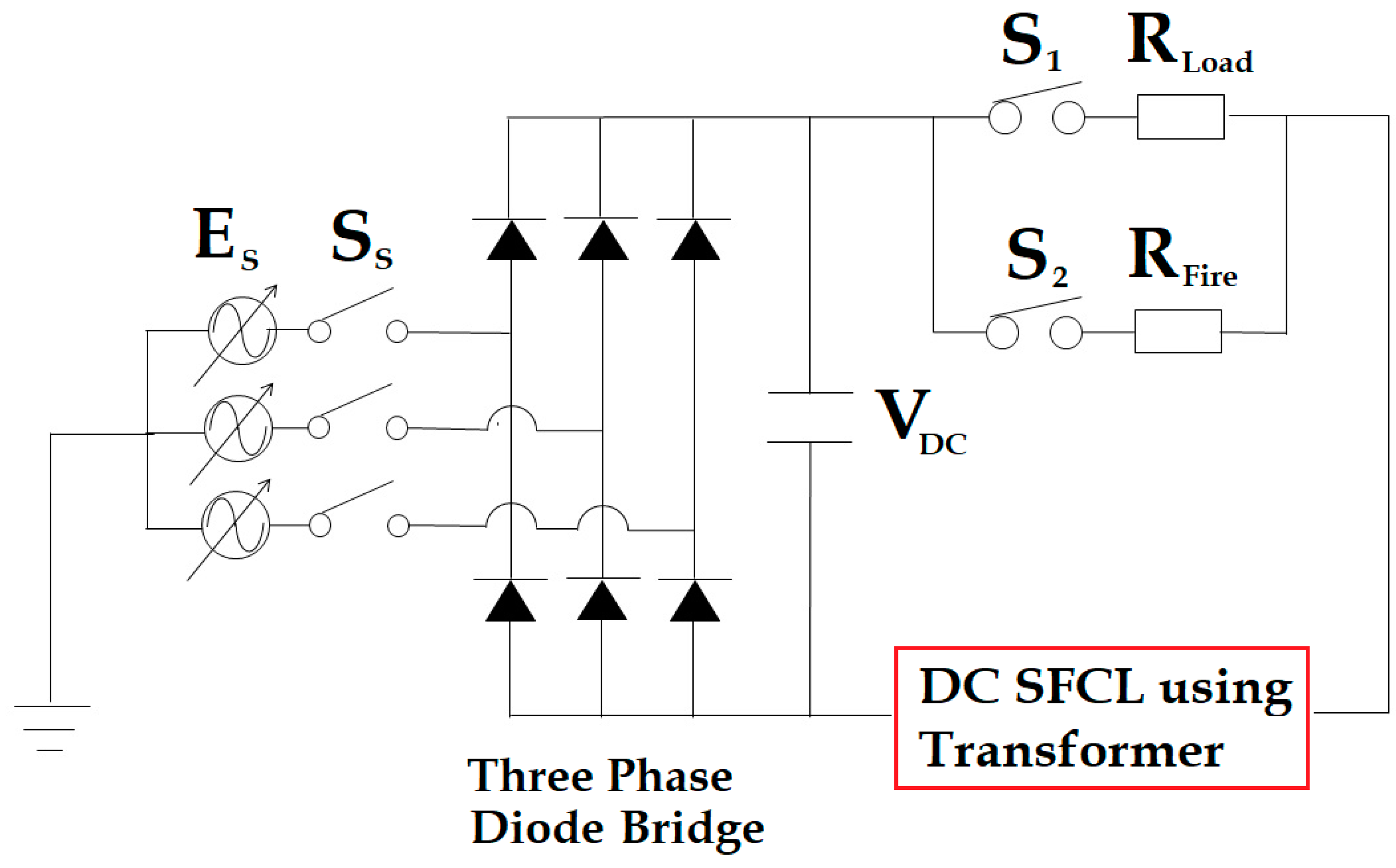
2.2. Experimental Structure and Method

To verify the fault current limiting operation of the proposed DC SFCL using a transformer, the DC short-circuit experiment was constructed, and the DC short-circuit tests were performed. Figure 3 is a schematic diagram of the DC experimental circuit with the DC SFCL using a transformer. A three-phase AC voltage (ES) was converted into a DC voltage (VDC) through a three-phase diode bridge rectifier. Normally, after the main power supplying switch SS is closed, S1 and S2 are respectively closed and opened. The current only flows into RLoad connected in series with S1. When S2 is closed, the current flows through RLoad and RFire. Since the equivalent resistance at this time is smaller than RLoad, a larger DC current flows into the DC SFCL and a DC short-circuit current can be simulated. In this paper, to simulate the larger current from the short circuit, S2 connected to RFire was set to be closed from 0.3 s to 0.4 s after S1 was connected to RLoad and closed at 0.1 s. Finally, the main switch SS was open to cut off the power supply.
The RSC1 superconducting element was connected in parallel with the primary winding of the transformer and the RSC2 superconducting element was connected with the secondary side of the transformer. One of two terminals of the CLR was connected in series with the primary winding of the transformer and other terminal of the CLR was connected in parallel with the RSC1 superconducting element. The superconducting elements, which was fabricated in Y1Ba2Cu3O7-x (YBCO) thin film form, were set in cryostat at a temperature of 77 K, which was full of liquid nitrogen [11,12,13,14]. To protect the superconducting elements used in the experiment, a shunt resistance was connected in parallel with each superconducting element. With consideration of the superconducting element having the normal resistance between 80 Ω and 100 Ω, a shunt resistance of 2.3 Ω as the lower value was selected. On the other hand, the total resistance of the superconducting element, including the lower value of the shunt resistor, is expected to be lower.
The main parameter values of experimental circuit, including the superconducting elements, are shown in Table 1. To investigate the DC fault current limiting characteristics of this SFCL due to the component of the CLR, the resistance and the inductance of the CLR were selected with three values, respectively, as listed in Table 1.

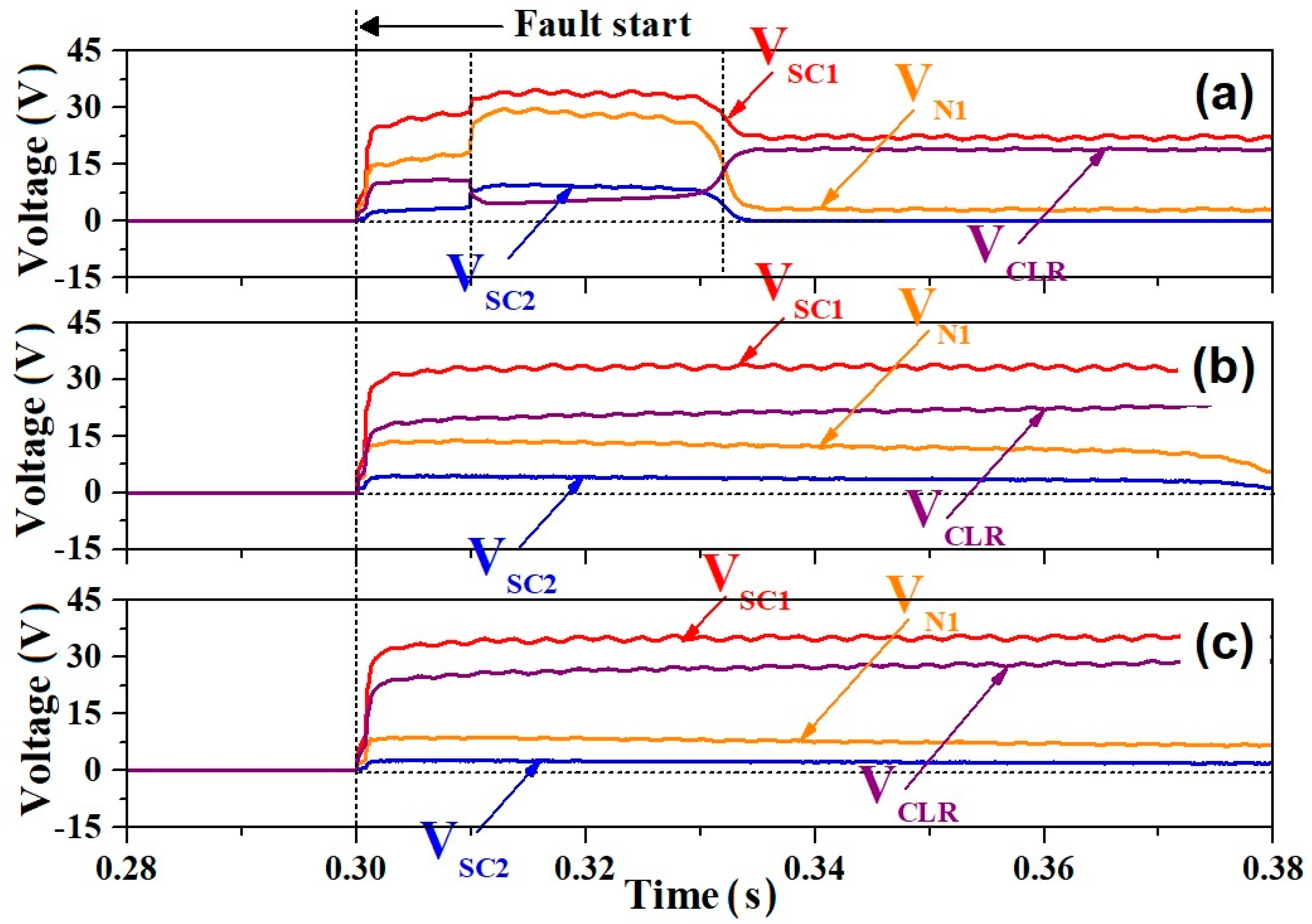
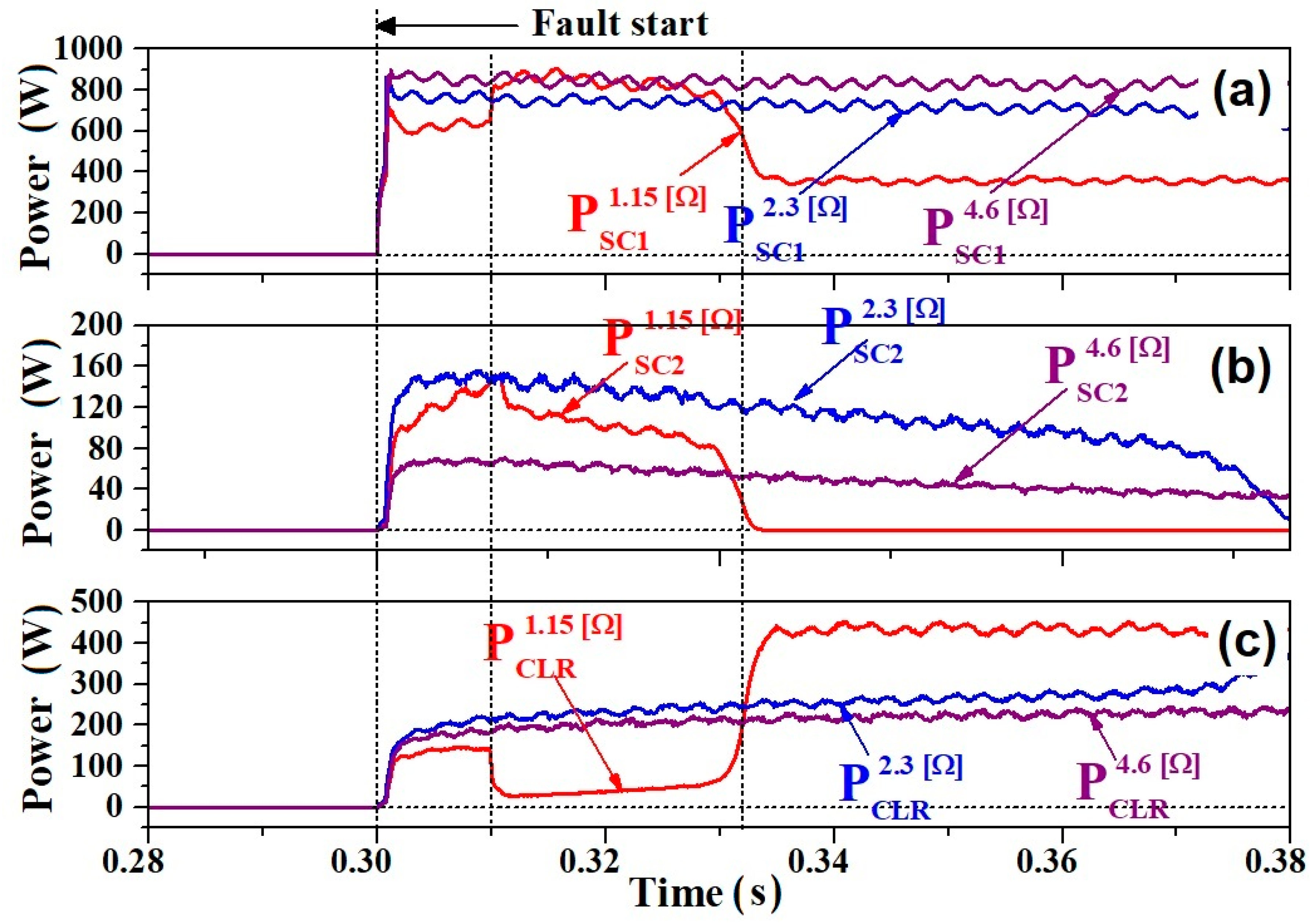
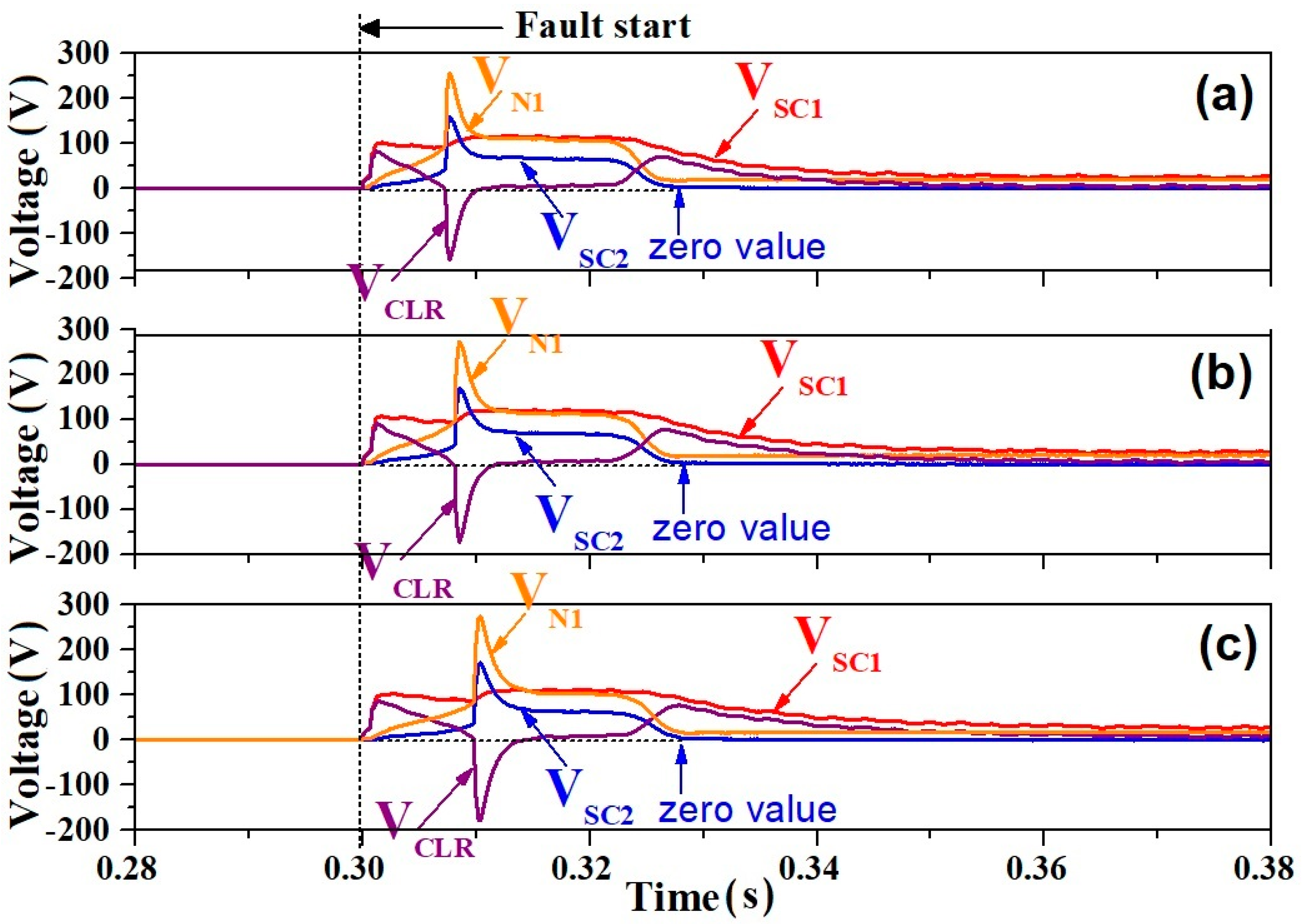
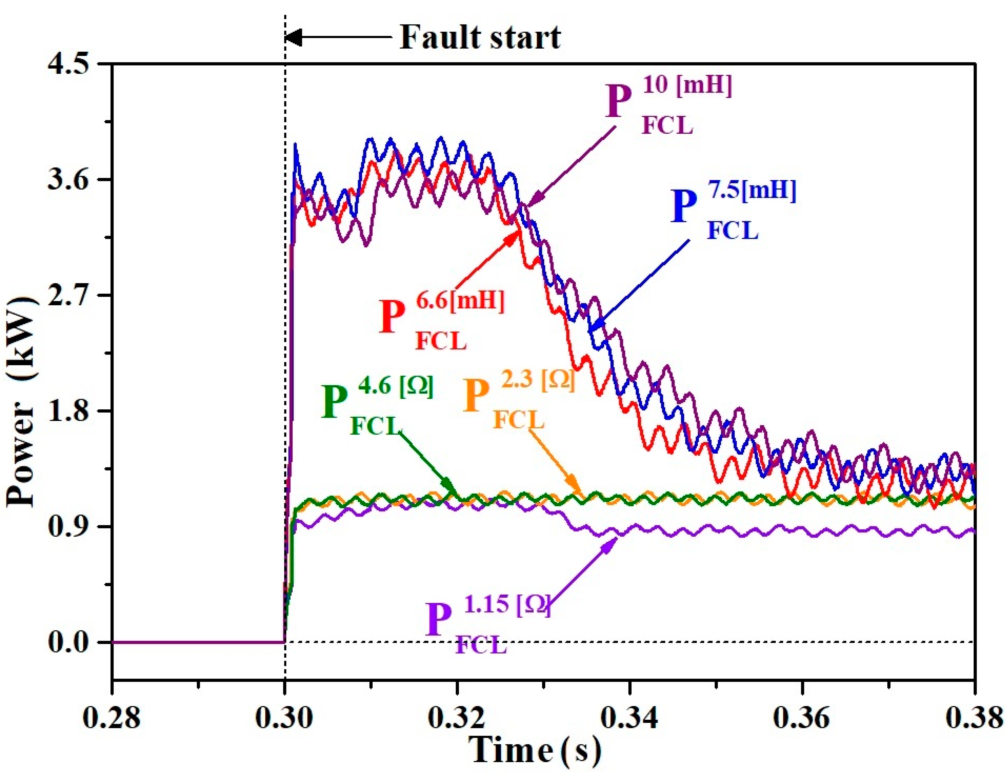
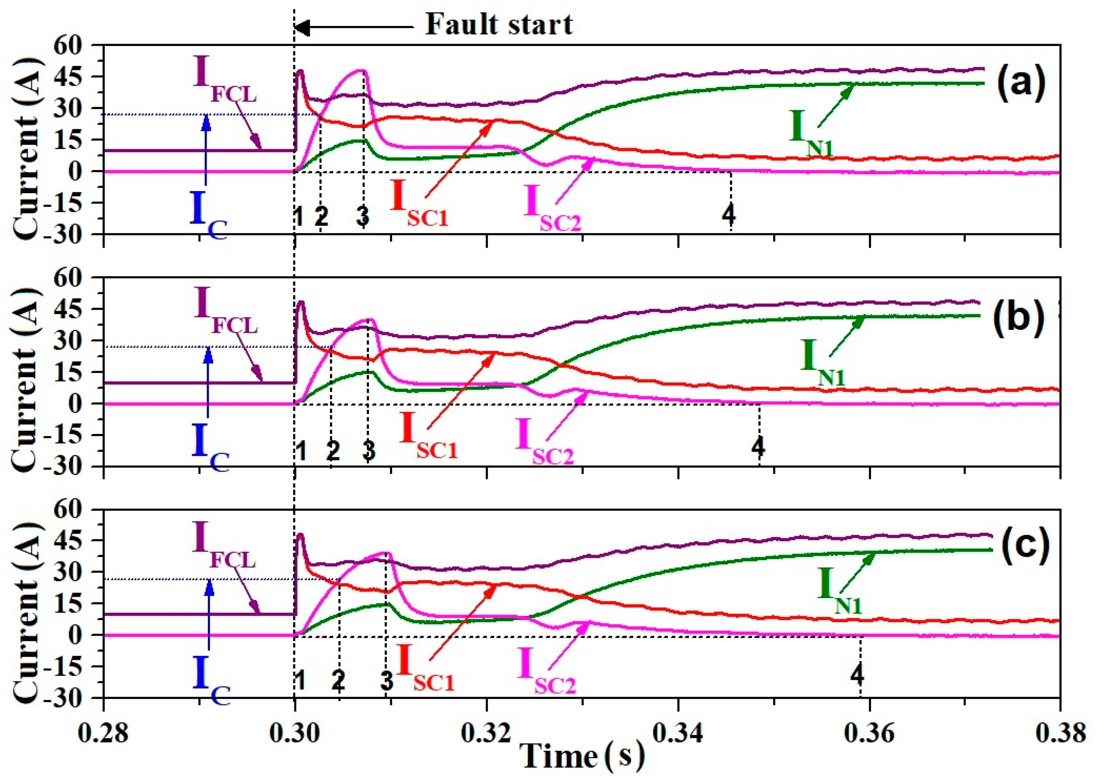
3. Result and Discussion

Figure 4 and Figure 5 show the current and the voltage waveforms when the CLR component is a resistance (RS). The DC fault current was generated by SW2 closing at 0.3 s. In case of RS = 1.15 Ω, as seen in Figure 5a, it could be observed that the voltages in the two superconducting elements (VSC1, VSC2) as well as the primary winding (VN1) were generated directly after the DC fault occurred. It could be confirmed from Figure 4a that the currents flowing into two superconducting elements (ISC1, ISC2) simultaneously exceeded the critical current (IC), which caused the voltages in the two superconducting elements.
Before about 0.31 s after the DC fault occurred, as indicated with the vertical dotted line in Figure 4a, the current in RSC1 (ISC1) sharply decreased and the currents in the primary winding and RSC2 (IN1, ISC2) increased. On the other hand, at the time of 0.31 s since the fault current occurred, the current in RSC2 (ISC2) together with the current of the primary winding (IN1) sharply started to decrease and the current in RSC1 (ISC1) smoothly started to increase. After about 0.33 s, as indicated with another vertical dotted line in Figure 4a, the superconducting element RSC2 was seen to be recovered into the superconducting state because the voltage (VSC2) dropped to the zero value, as seen in Figure 5a, which made the current in RSC2 (ISC2) to have a zero value. Despite the zero current in RSC2, the non-zero current in the primary winding (IN1) is thought to be a result of the magnetizing inductance of the iron core comprising the transformer.
From the viewpoint of the electrical circuit, the DC SFCL with a parallel structure, which consisted of both the RSC1 and the transformer, including RSC2, has been analyzed to be applied to increase the limited current in the load (IFCL) because the load current can be divided into the superconducting element RSC1 (ISC1) and the primary winding of the transformer (IN1) after the current in RSC1 by its quench occurrence is limited. The current in RSC2 (ISC2) was almost three times that of the current in the primary of the transformer (IN1) by the turn ratio of the transformer.
In case of RS = 2.3 Ω, as shown in Figure 4b, although the currents flowing into the two superconducting elements (ISC1, ISC2) seemed to simultaneously exceed the critical current, the current in the primary winding of the transformer (IN1), i.e., the current of the CLR, did not largely increase in the initial fault time because of the larger resistance of the CLR than the CLR with 1.15 Ω. It makes the voltage across the primary winding of the transformer (VN1) steadily decreasing, as seen in Figure 5b. In case of RS = 4.6 Ω, the current and the voltage waveforms were observed to be almost similar to the case of RS = 2.3 Ω, as shown in Figure 4c and Figure 5c, except that the amplitude of the induced voltage in the primary winding of the transformer (VN1) was more smaller than in the case of RS = 2.3 Ω. Instead, the voltage across the CLR (VCLR) was shown to have an opposite trend to the one in the primary winding of the transformer (VN1).
Figure 6 shows the instantaneous power waveforms of RSC1, RSC2, and CLR due to the CLR’s resistance. In the case of RS = 1.15 Ω, the initial larger power burden in the RSC1 superconducting element (PSC1) directly after the fault occurrence could be observed to be shared with the CLR after the voltage of the RSC2 superconducting element (VSC2) recovered into the zero value, as previously shown in Figure 5a. On the other hand, in the case of the CLR’s resistance with a larger value (RS = 2.3 Ω, RS = 4.6 Ω) than RS = 1.15 Ω, the power burden in RSC1 with a CLR of RS = 4.6 Ω was observed to be more larger than the one in RSC1 with a CLR of RS = 2.3 Ω, as seen in Figure 6a. On the other hand, in the case of RSC1 with a CLR of RS = 4.6 Ω, the power burden in RSC2 was more decreased than the one in RSC2 with a CLR of RS = 2.3 Ω, as compared in Figure 6b. In addition, a CLR with an RS = 2.3 Ω had a little more of a power burden than the one with an RS = 4.6 Ω, as seen in Figure 6c.
From the above analysis, it was confirmed that a CLR with a larger resistance could derive the higher power burden in RSC1 and the lower power burden in the CLR as well.
Figure 7 shows the current waveform in the case that the component of the CLR is an inductance. Similar to the case that the component of the CLR is a resistance, as shown in Figure 5, the limited current in the DC SFCL (IFCL) was observed to be divided into the current in RSC1 and the primary of the transformer (ISC1, IN1). On the other hand, unlike the CLR with the resistance, the current in the RSC2 superconducting element slowly increases after the DC fault occurrence, and then approaches the peak value (“3” point) only after it exceeds the critical current (“2” point). With a larger inductance of the CLR, the peak value of the current in RSC2 is observed to be decreased, as seen in Figure 7. On the other hand, after the current of RSC2 approaches the peak value, the approaching time into the zero value (“4” point) takes more time with a larger inductance of the CLR. However, despite the larger inductance of the CLR, the DC fault current limiting effect, after the current in RSC2 approaches the peak value, could be not seen, as compared to that in Figure 7c.
Figure 8 shows the voltage waveform in case that a component of the CLR was selected as the inductance. After the DC fault occurs, the voltage across the CLR (VCLR), which sharply increased into the plus peak value, jumped down into the minus peak value through the zero value and then, again, decreased into the zero value. It is thought to be related to the variation in the current in the primary winding of the transformer (IN1), i.e., the current in the CLR due to the resistance generation of the superconducting element (RSC2). Although the resistances in RSC1 and RSC2 gradually decrease after the current in RSC2 (ISC2) approaches a zero value (“4” point), as shown in Figure 7, the fault current (IFCL) can be seen to be mostly divided into the primary winding of the transformer (IN1) and the RSC1 superconducting element (ISC1).
Figure 9 shows the instantaneous power waveforms of RSC1, RSC2, and the CLR due to the CLR’s inductance. As the inductance of the CLR comprising the DC SFCL increases from 6.6 mH to 10 mH, the time in which the instantaneous power in the RSC2 superconducting element (PSC2) arrives to its first peak value is seen to be delayed. Unlike the CLR with the resistance, as shown in Figure 6, the power burdens in RSC1 and RSC2 (PSC1, PSC2) were shown to be increased (higher). On the other hand, after the voltage in RSC2 (VSC2) decreases and drops down to a zero value (as seen in Figure 8), the power burden in the RSC2 superconducting element (PSC2) also disappears—almost at the same time—regardless of the inductance value of the CLR, as displayed in Figure 9b.
Figure 10 shows the DC fault current waveforms of the DC SFCL using the transformer according to a component of the CLR. As described in the above figure, the CLR with the inductance has little effect on the DC fault current limiting operation of the DC SFCL using a transformer, except for the initial fault occurrence period in which the DC fault current rises up. The resistance generations of the two superconducting elements (RSC1, RSC2) are thought to be just contributed to the DC current limiting operation flowing into each superconducting element. On the other hand, the CLR with the resistance, if its resistance is higher, was confirmed to have an effective DC fault current limiting operation through the resistance generation of the two superconducting elements.
The instantaneous power waveforms of the DC SFCL using the transformer according to the CLR component are also shown in Figure 11. The larger power burden in the DC SFCL with the CLR of the inductance, for the transient initial fault period, was analyzed to be much more focused on two superconducting elements, which agreed with the analysis from Figure 9. It was found that the DC SFCL with the CLR of the resistance had shown the more effective DC fault current limiting operation through the resistance generation of the two superconducting elements together with the lower power burden of the DC SFCL.

4. Conclusions

In this paper, as one of the DC SFCLs with two triggering current levels, the DC SFCL using a transformer was suggested, and its DC fault current limiting characteristics due to the component of the CLR comprising the DC SFCL using a transformer were analyzed.
In case of the DC SFCL with the CLR as the resistance, the quench in the two superconducting elements almost simultaneously occurred, and the DC fault current could be limited through the slowly increased resistance generation after the sharp increase in the two superconducting elements. Furthermore, the DC SFCL with the CLR, designed with a larger resistance, could derive the higher power burden in RSC1 and the lower power burden in CLR.
On the other hand, the DC SFCL with the CLR as the inductance had little effect on the DC fault current limiting operation, although the initial rising of the DC fault current could be suppressed. In addition, the power burdens of RSC1 and RSC2 in the DC SFCL with the CLR as the inductance were shown to be increased higher than the one with the CLR as the resistance, regardless of the inductance value of the CLR.
In the future, the DC fault current limiting characteristics of the DC SFCL, which has an advantage from the point of view of the DC fault current limiting operation and the DC power burden, will be reported.

Author Contributions

Writing—review & editing and experiments, K.-C.C. and S.-H.L.; experiment support, M.-K.P. All authors have read and agreed to the published version of the manuscript.

Funding

This research was supported by Korea Electric Power Corporation (Grant number: R18XA04) and also supported by the National Research Foundation of Korea (NRF) grant funded by the Korea government (MOE) (No. 2020R1F1A1077206).

Conflicts of Interest

The authors declare no conflict of interest.

References

  1. Zhou, Y.; Zhuojiang, D.; Fenwang, Y. The Development of HVDC Transmission System. In Proceedings of the Digital Manufacturing and Automation (ICDMA), 2012 Third International Conference, Guilin, China, 31 July–2 August 2012; pp. 907–910. [Google Scholar]
  2. Okba, M.H.; Saied, M.H.; Mostafa, M.Z.; Abdel-Moneim, T.M. High voltage direct current transmission—A review, part I. In Proceedings of the 2012 IEEE Energytech, Cleveland, OH, USA, 30–31 May 2012; pp. 1–7. [Google Scholar]
  3. Moon, H.B. High Voltage Direct Current Technology Trends. J. Electr. World Mon. Mag. Korea Electr. Assoc. 2009, 392, 29–37. [Google Scholar]
  4. Ganhao, Z. Study on DC Circuit Breaker. In Proceedings of the 2014 Fifth International Conference on Intelligent Systems Design and Engineering Applications (ISDEA), Hunan, China, 15–16 June 2014; pp. 942–945. [Google Scholar]
  5. Bae, S.H.; Kim, H.R.; Park, J.W.; Lee, S.H. A Study on SFCL with IGBT Based DC Circuit Breaker in Electric Power Grid. J. Elect. Eng. Technol. 2017, 12, 1805–1811. [Google Scholar]
  6. Lim, S.H.; You, I.K.; Kim, J.C. Study on Peak Current Limiting Characteristics of a Flux-Lock Type SFCL Using Its Third Winding. IEEE Trans. Appl. Supercond. 2011, 21, 1275–1279. [Google Scholar] [CrossRef]
  7. Ko, S.C.; Lim, S.H. Analysis on Magnetizing Characteristics Due to Peak Fault Current Limiting Operation of a Modified Flux-Lock-Type SFCL With Two Magnetic Paths. IEEE Trans. Appl. Supercond. 2016, 26, 5601605. [Google Scholar] [CrossRef]
  8. Lee, B.W.; Park, K.B.; Sim, J.; Oh, I.S.; Lee, H.G.; Kim, H.R.; Hyun, O.B. Design and Experiments of Novel Hybrid Type Superconducting Fault Current Limiters. IEEE Trans. Appl. Supercond. 2008, 18, 624–627. [Google Scholar] [CrossRef]
  9. Chen, Y.; Liu, X.; Sheng, J.; Cai, L.; Jin, Z.; Gu, J.; An, Z.; Yang, X.; Hong, Z. Design and Application of a Superconducting Fault Current Limiter in DC Systems. IEEE Trans. Appl. Supercond. 2014, 24, 5601305. [Google Scholar] [CrossRef]
  10. Liang, S.; Tang, Y.; Xia, Z.; Ren, L.; Chen, L.; Xu, Y.; Wang, Z.; Yan, S. Study on the Current Limiting Performance of a Novel SFCL in DC Systems. IEEE Trans. Appl. Supercond. 2017, 27, 5601106. [Google Scholar] [CrossRef]
  11. Lim, S.H.; Choi, H.-S.; Chung, D.-C.; Jeong, Y.-H.; Han, Y.-H.; Sung, T.-H.; Han, B.-S. Fault Current Limiting Characteristics of Resistive Type SFCL using a Transformer. IEEE Trans. Appl. Supercond. 2005, 15, 2055–2058. [Google Scholar] [CrossRef]
  12. Lim, S.H.; Cho, Y.S.; Choi, H.S.; Han, B.S. Improvement of Current Limiting Capability of HTSC Elements in Hybrid Type SFCL. IEEE Trans. Appl. Supercond. 2007, 17, 1807–1810. [Google Scholar] [CrossRef]
  13. Lim, S.T.; Ko, S.C.; Lim, S.H. Analysis on Current Limiting Characteristics of Transformer Type SFCL with Additionally Coupled Circuit. J. Elect. Eng. Technol. 2018, 13, 533–539. [Google Scholar]
  14. Lim, S.T.; Lim, S.H.; Han, T.H. Analysis on Operation Characteristics and Power Burdens of the Double Quench Trigger Type SFCLs. Prog. Supercond. Cryog. 2017, 19, 33–37. [Google Scholar]
  15. Lee, H.J.; Kim, J.S.; Lim, S.H.; Kim, J.C. Analysis on Operational Characteristics of Double Quench Flux Lock Type Superconducting Fault Current Limiter. IEEE Trans. Appl. Supercond. 2020, 30, 5600505. [Google Scholar]
  16. Lim, S.H. Study on Current Limiting Characteristics of SFCL with Two Trigger Current Levels. Physica C 2010, 445, 1631–1635. [Google Scholar] [CrossRef]
  17. Martini, L.; Bocchi, M.; Angeli, G.; Ascade, M.; Rossi, V.; Valzasina, A.; Ravetta, C.; Fratti, S.; Martino, E. Live Grid Field-Testing Final Results of the First Italian Superconducting Fault Current Limiter and Severe 3-Phase Fault Experience. IEEE Trans. Appl. Supercond. 2015, 25, 5600405. [Google Scholar] [CrossRef]
  18. Naoki, H.; Yuya, M.; Hiroki, K. Fault Current Limitation Coordination in Electric Power Grid with Superconducting Fault Current Limiters. IEEE Trans. Appl. Supercond. 2018, 28, 5602304. [Google Scholar]
  19. Hyun, O.B.; Yim, S.W.; Yu, S.D.; Yang, S.E.; Kim, W.S.; Kim, H.R.; Lee, G.H.; Sim, J.; Park, K.B. Long-Term Operation and Fault Tests of a 22.9 kV Hybrid SFCL in the KEPCO Test Grid. IEEE Trans. Appl. Supercond. 2011, 21, 2131–2134. [Google Scholar] [CrossRef]
  20. Kim, H.R.; Yang, S.E.; Yu, S.D.; Kim, H.; Park, B.J.; Han, Y.H.; Park, K.; Yu, J. Development and Grid Operation of Superconducting Fault Current Limiters in KEPCO. IEEE Trans. Appl. Supercond. 2014, 24, 5602504. [Google Scholar]
  21. Lee, H.S.; Jung, C.; Song, C.S.; Lee, S.R.; Yang, B.M.; Jang, G. Novel Protection Scheme with the Superconducting Power Cables and Fault Current Limiters through RTDS Test in Icheon Substation. IEEE Trans. Appl. Supercond. 2012, 22, 4705304. [Google Scholar]
  22. Han, Y.H.; Yang, S.; Kim, H.; Park, B.J.; Yu, J.; Kim, H.R.; In, S.; Hong, Y.J.; Yeom, H. Development and Long-Term Test of a Compact 154 kV SFCL. IEEE Trans. Appl. Supercond. 2019, 29, 5600106. [Google Scholar] [CrossRef]
Figure 1. Configuration of the DC superconducting fault current limiter (SFCL).
Energies 13 04210 g001
Figure 2. Configuration of DC SFCL using a transformer.
Energies 13 04210 g002
Figure 3. Schematic diagram of the DC experimental circuit with a DC SFCL using a transformer.
Energies 13 04210 g003
Figure 4. Current waveforms due to the CLR’s resistance: (a) RS = 1.15 Ω; (b) RS = 2.3 Ω; (c) RS = 4.6 Ω.
Energies 13 04210 g004
Figure 5. Voltage waveforms due to the CLR’s resistance: (a) RS = 1.15 Ω; (b) RS = 2.3 Ω; (c) RS = 4.6 Ω.
Energies 13 04210 g005
Figure 6. Instantaneous power waveforms due to the CLR’s resistance: (a) power burden arising from RSC1 element depending on the CLR’s resistance; (b) power burden arising from the RSC2 element depending on the CLR’s resistance; (c) power burden arising from the CLR depending on the CLR’s resistance.
Energies 13 04210 g006
Figure 7. Current waveforms due to the CLR’s inductance: (a) LS = 6.6 mH; (b) LS = 7.5 mH; (c) LS = 10 mH.
Energies 13 04210 g007
Figure 8. Voltage waveforms due to the CLR’s inductance: (a) LS = 6.6 mH; (b) LS = 7.5 mH; (c) LS = 10 mH.
Energies 13 04210 g008
Figure 9. Instantaneous power waveforms due to the CLR’s inductance: (a) power burden arising from the RSC1 element depending on the CLR’s inductance; (b) power burden arising from the RSC2 element depending on the CLR’s inductance; (c) power burden arising from the CLR depending on the CLR’s inductance.
Energies 13 04210 g009
Figure 10. Comparative DC fault current waveforms of the DC SFCL using a transformer dependent on the CLR’s component.
Energies 13 04210 g010
Figure 11. Comparative instantaneous power waveforms of the DC SFCL using a transformer dependent on the CLR’s component.
Energies 13 04210 g011
Table 1. Main parameter values of the experimental circuit.
DC Test CircuitValueUnit
VDC110V
RLoad10
RFire2.5
Transformer and CLRValueUnit
Turns Ratio (N1/N2)3
CLR (RS)4.6/2.3/1.15
CLR (LS)6.6/7.5/10mH
Superconducting elements (Rsc1 and Rsc2)ValueUnit
Fabrication TypeThin Film
MaterialYBCO
Critical Current25A
Total Meander Line Length420mm
Line Width2mm
Thin Film Thickness0.3μm
Gold Layer Thickness0.2μm

